polydrain - abt inc
TRANSCRIPT
PolyDrain
Pre-Engineered Surface Drainage
Installation Guide
P.O. Box 837 - 259 Murdock Road - Troutman, NC 28166
Tel (704) 528-9806 - Fax (704) 528-5478 - www.abtdrains.com
Toll free in the USA, Canada, and Mexico (800) 438-6057
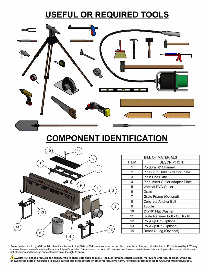
BILL OF MATERIALS
DESCRIPTIONITEM
PolyDrain® Channel1
Pipe Stub Outlet Adaptor Plate2
Plain End Plate3
Pipe Insert Outlet Adapter Plate4
Vertical PVC Outlet5
Grate6
Grate Frame (Optional)7
Concrete Anchor Bolt8
Toggle9
Ø5/16" Flat Washer10
Grate Retainer Bolt - Ø5/16-1811
PolyClip I™ (Optional)12
PolyClip II™ (Optional)13
Rebar U-Leg (Optional)14
USEFUL OR REQUIRED TOOLS
COMPONENT IDENTIFICATION
11
6
1
7
9
2
3
5
13
12
14
10
4
8
Some products sold by ABT contain chemicals known to the State of California to cause cancer, birth defects or other reproductive harm. Products sold by ABT may
contain these chemicals in a smaller amount than Proposition 65's concern, or not at all, however, we have chosen to issue this warning on all of our products as an
act of caution and because our customers have the right to know.
WARNING: These products can expose you to chemicals such as nickel, lead, chromium, cobalt, styrene, methylene chloride, or silica, which are
known to the State of California to cause cancer and birth defects or other reproductive harm. For more information go to www.P65Warnings.ca.gov.
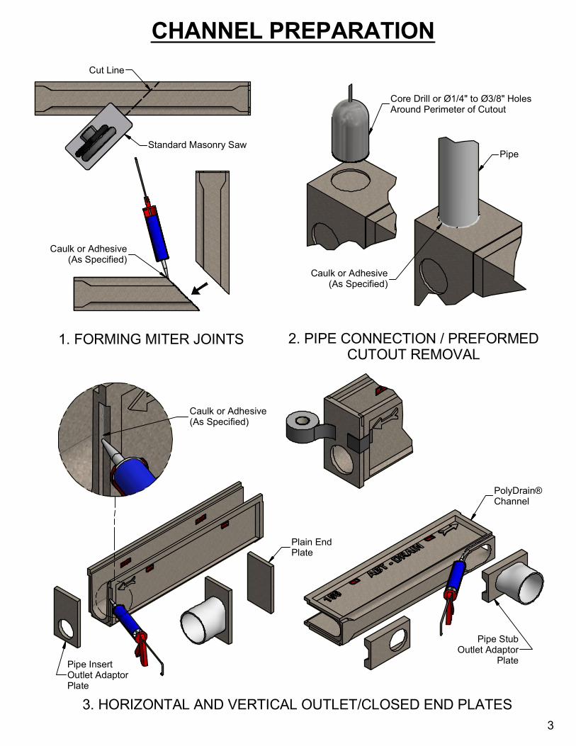
1. FORMING MITER JOINTS2. PIPE CONNECTION / PREFORMED
CUTOUT REMOVAL
3. HORIZONTAL AND VERTICAL OUTLET/CLOSED END PLATES
Cut Line
Caulk or Adhesive
(As Specified)
Core Drill or Ø1/4" to Ø3/8" Holes
Around Perimeter of Cutout
Pipe
PolyDrain®
Channel
Plain End
Plate
Pipe Insert
Outlet Adaptor
Plate
Pipe Stub
Outlet Adaptor
Plate
Caulk or Adhesive
(As Specified)
CHANNEL PREPARATION
Standard Masonry Saw
3
Caulk or Adhesive
(As Specified)
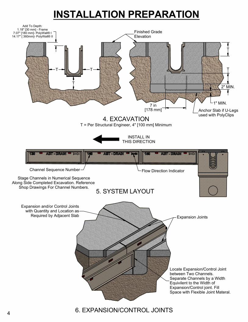
5. SYSTEM LAYOUT
4. EXCAVATION
T = Per Structural Engineer, 4" [100 mm] Minimum
6. EXPANSION/CONTROL JOINTS
INSTALL IN
THIS DIRECTION
INSTALLATION PREPARATION
Channel Sequence Number
Flow Direction Indicator
Stage Channels in Numerical Sequence
Along Side Completed Excavation. Reference
Shop Drawings For Channel Numbers.
Add To Depth:
1.18" [30 mm] - Frame
7.07" [180 mm]- PolyWall® I
14.17" [ 360mm]- PolyWall® II
T TT
Finished Grade
Elevation
T
Expansion and/or Control Joints
with Quantity and Location as
Required by Adjacent Slab
Locate Expansion/Control Joint
between Two Channels.
Separate Channels by a Width
Equivilent to the Width of
Expansion/Control joint. Fill
Space with Flexible Joint Materal.
4
Anchor Slab if U-Legs
used with PolyClips
T
Expansion Joints
1" MIN.
2" MIN.
7 in
[178 mm]
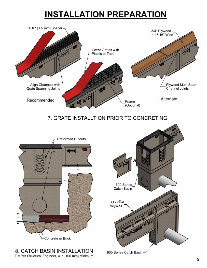
7. GRATE INSTALLTION PRIOR TO CONCRETING
8. CATCH BASIN INSTALLATION
T = Per Structural Engineer, 4 in [100 mm] Minimum
INSTALLATION PREPARATION
1/16" [1.5 mm] Spacer
Cover Grates with
Plastic or Tape
Align Channels with
Grate Spanning Joints
Plywood Must Span
Channel Joints
Recommended
Alternate
3/4" Plywood -
4-15/16" Wide
5
600 Series
Catch Basin
900 Series Catch Basin
Optional
PolyWall
Preformed Cutouts
T
T
T
Concrete or Brick
Frame
(Optional)

9A. CHANNEL INSTALLATION WITH POLYCLIP I™
9B. CHANNEL INSTALLATION WITH POLYCLIP II™
CHANNEL INSTALLATION
Important Installation Notes:
1. Begin Installation at Outlet/Discharge End and Work Backwords (Upstream).
2. Piping Connections, Catch Basin Installation, Miter Joint Assembly, and Trench
Excavation Must be Completed Prior to Channel Installation.
3. Set String Line to Finished Slab Height at Outside Edge of Proposed Channel Location.
4. There are (4) Basic Methods of PolyDrain® Channel Installation:
A. PolyClip I Installation Device
B. PolyClip II Installation Device.
C. Suspended Installation
D. Bedding Slurry Installation
Back Wingnut to End of
Threaded Crossrod and
Spread Clips to Limit.
Position Bracket as Shown
and Tighten Wingnut.
Bracket Spans
Channel Joint
PolyClip I™ Bracket
Covered Grates or Plywood -
to Ensure Proper Alignment.
Refer to Step 7.
Adjust U-Leg to Achieve
Proper Slab Height
Toenail PolyClip I to Ground
with #3 or #4 Rebar. Use Anchor
Slab if Toenailing not Usable.
Bracket Spans
Channel Joint
PolyClip II™
Bracket
Loosen Nuts to
Slide Securing
Clips Apart. Place
Channel on Base.
6
Rebar
(Anchor Slab
Optional)
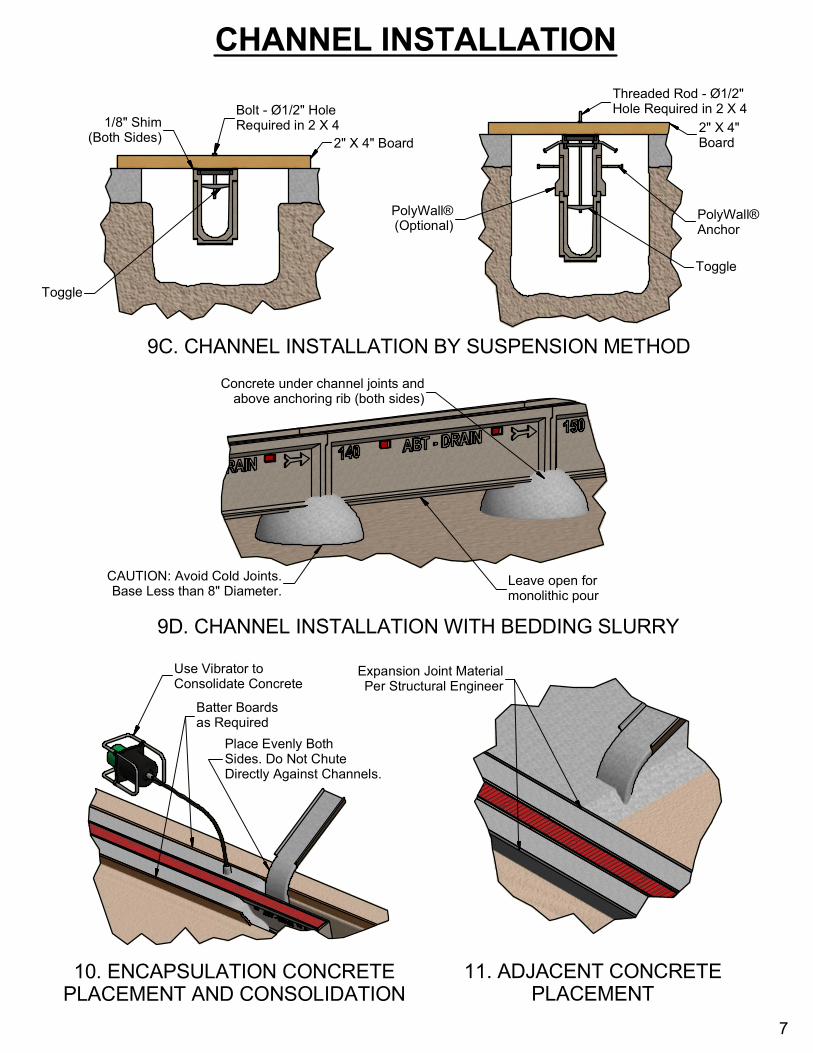
9C. CHANNEL INSTALLATION BY SUSPENSION METHOD
9D. CHANNEL INSTALLATION WITH BEDDING SLURRY
10. ENCAPSULATION CONCRETE
PLACEMENT AND CONSOLIDATION
11. ADJACENT CONCRETE
PLACEMENT
CHANNEL INSTALLATION
Bolt - Ø1/2" Hole
Required in 2 X 4
Threaded Rod - Ø1/2"
Hole Required in 2 X 4
1/8" Shim
(Both Sides)
2" X 4" Board
2" X 4"
Board
Toggle
Toggle
PolyWall®
(Optional)
PolyWall®
Anchor
Leave open for
monolithic pour
CAUTION: Avoid Cold Joints.
Base Less than 8" Diameter.
Concrete under channel joints and
above anchoring rib (both sides)
Place Evenly Both
Sides. Do Not Chute
Directly Against Channels.
7
Use Vibrator to
Consolidate Concrete
Batter Boards
as Required
Expansion Joint Material
Per Structural Engineer

12A. GRATE INSTALLATION - TOGGLE & RED DOT
12B. GRATE INSTALLATION - TOGGLE UNDER FRAME
GRATE INSTALLATION
Tighten Screw. See
Torque Specs at
www.abtdrains.com
Remove all Debris from
Grate Seat Surfaces
Rotate Toggle to Clear
Channel/Frame During
Grate Placement
Locate Grates to
have 1/8" [3 mm]
Gap Betweeen Ends
(3) Conical Washers
Refer to Website for
Additional Information
REV 030719.00