polarography and voltammetry : basic principles applications
TRANSCRIPT

POLAROGRAPHY AND VOLTAMMETRY :
BASIC PRINCIPLES
APPLICATIONS
&

Polarography & Voltammetry:ELECTRO-ANALYTICAL
TECHNIQUES
Qualitative
Quantitative
In one step analysis
Metals
Other inorganics
Organics
NATURE OF SAMPLE
Practically any
LOD
10-5 → 10-15 M
g → pg

OF
ANALYTE SOLUTION
A MICRO SCALE
“ELECTROLYSIS”

REQUIREMENTS :
Analyte, be
AN OXIDIZABLE / REDUCIBLE SPECIES
(Directly or indirectly)
IN SOLUTION
Aqueous
Non Aqueous

BASIC APPARATUS / MATERIALS REQUIRED
1. Cell : A container to hold the analyte solution
2. Electrodes
3. Voltage Supply (Variable DC/AC) / (Potentiostat)
4. Voltmeter
5. Ammeter
( Classical technique: 2 : RE & WE )
( Modern techniques: 3: RE, WE & CE)

FOR ELECTROLYSIS TO OCCUR:
E “WE” > E eqbm l
i.e.
For “Oxidation” : E “WE” more (+)ve than E eqbm
For “Reduction” : E “WE” more (-)ve than E eqbm

REPRESENTATION OF A SIMPLE SETUP WITH
A TWO ELECTRODE CELL
Voltage supply
AV
Analyte solution
R.EW.E.
W.E. = Working Electrode
R.E. = Reference Electrode
V = Voltmeter
A = Ammeter

WHAT DO WE MEASURE IN 2
ELECTRODE CELLS ?
BOTH
Potential of the cell
Current through the circuit

REPRESENTATION OF A MORDEN VOLTAMMETRIC
SETUP: WITH A THREE ELECTRODE CELL
WITH A POTENTIOSTAT
A
V
Potentiometer
voltmeter
Ammeter Electrolysis
cell
Counter
electrode
Reference electrode
(working
electrode)

WHAT DO WE MEASURE IN
3 - ELECTRODE CELLS ?
BOTH
Potential of “WE” vs “RE”
Current via “WE” & “CE”

CELL CURRENT
POTENTIAL OF “WE”
Quantification
Identification

WE: Dropping Mercury Electrode:
“Polarography”
WE: Other electrodes, mostly solids:
“Voltammetry”
ION TRANSPORT DURING ELECTROLYSIS
MIGRATION
DIFFUSION
CONVECTION

MIGRATION
Movement of oppositely charged ions towards electrode due
to electrostatic attractions.
+++
WE
+
+
- -- ---
- -

Diffusion
+++
WE
+
+
- -- ---
- -
DIFFUSION
Movement of ions from region of higher concentration (bulk)
to region of lower concentration (near the electrode surface)

Convection
Transport of ions towards electrode due to agitation, vibration
and temperature gradients
+++
WE
+
+
- ++ ---
+ +++
+
+
-
-
-
-

THE TWO MAJOR DIVISIONS IN
VOLTAMMETRY
1. Voltammetry under diffusion controlled
mass (ion) transfer
eg: Polarography, LSV, CV, NPP, DPP, etc.

2. Voltammetry under convection controlled
mass (ion) transfer
a) Movement of electrode in a still solution which promote
„convection‟
b) Movement of solution past the stationary electrode
eg: electrochemical detection for LC where „flow cells‟,
„channel electrode‟ (wall jet electrode) are used.
THE TWO MAJOR DIVISIONS IN
VOLTAMMETRY (cont’d)
eg: RDE, RRDE

VOLTAMMETRY UNDER DIFFUSION
CONTROL MASS TRANSFER
NO MIGRATION
NO CONVECTION
How to achieve this condition?
ONLY DIFFUSION

METHODS OF STOPPING OR MINIMIZING
MIGRATION
Add an excess ( 100 fold or more) an inert
electrolyte to the analyte solution
This screens the electric field produced by the
electrode
Add an excess ( 100 fold or more) an inert
electrolyte to the analyte solution
Therefore no attraction of ions from the bulk to the electrode
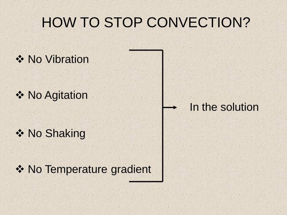
HOW TO STOP CONVECTION?
No Vibration
No Agitation
No Shaking
No Temperature gradient
In the solution

MASS TRANSPORT
ONLY BY
“DIFFUSION”

CONCENTRATION POLARIZATION
Species
concentration at
the electrode
surface
Species
concentration in
the bulk

CONCENTRATION PROFILES
x = distance away from electrode surface
C = Concentration
From time t4 onwards surface concentrations are zero
Beyond the time t6, no change in concentration profile with time
i.e. steady state has been reached
t6>t5>t4>t3>t2>t1
t1t2
t3 t4
t5t6
C
x

AT STEADY STATE:
Rate of
removed of
ions at the
electrode
Rate of
supply of
ions from the
bulk to the
electrode

Rate of ion removal
Rate ofsupply of ion
Concentration
Cell Current, I
Cell Current, I
Cell Current, I

POLARIZATION OF ELECTRODES
Polarized Electrodes
Non Polarized Electrodes

POLARIZED ELECTRODES
Current, I, remains unchanged with changes in the
electrode potential, E.
AB
Over the potential range A to B the electrode is polarized
I
E

AT STEADY STATE :
“WE” is polarized
A condition necessary for voltammetry
Note 1: Microelectrodes reaches the state
of polarization very rapidly
2: Current is very small < μA – pA, as a
result at the end of the analysis original
concentration of the solution remains
unchanged
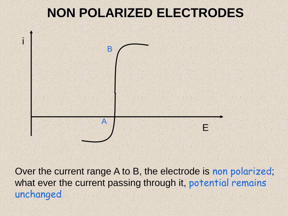
NON POLARIZED ELECTRODES
A
Bi
E
Over the current range A to B, the electrode is non polarized;
what ever the current passing through it, potential remains unchanged

VOLTAMMETRY NEEDS A NON
POLARIZED ELECTRODE
Reference electrodes have this property
over a limited current range
Therefore reference electrode use in
voltammetry

Normal voltammetryDifferential Pulse
Polarography
Square wave voltammetry Cycle voltammetry
Different Methods of Variations of potential of WE

POLAROGRAPHY
WE : Dropping Mercury Electrode (DME)
Capillary id = 0.05 mm
mercury = (20 – 100) cm

CLASSICAL POLAROGRAPHY
E
Time
Potential ramp Polarogram
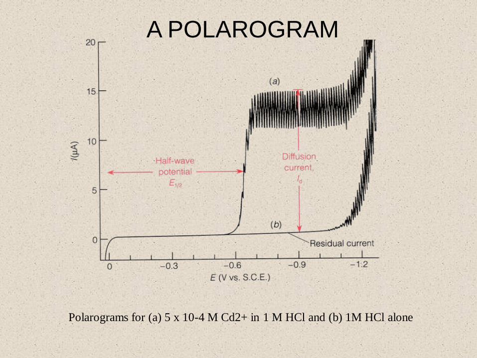
Polarograms for (a) 5 x 10⁻⁴ M Cd2+ in 1 M HCl and (b) 1M HCl alone
A POLAROGRAM
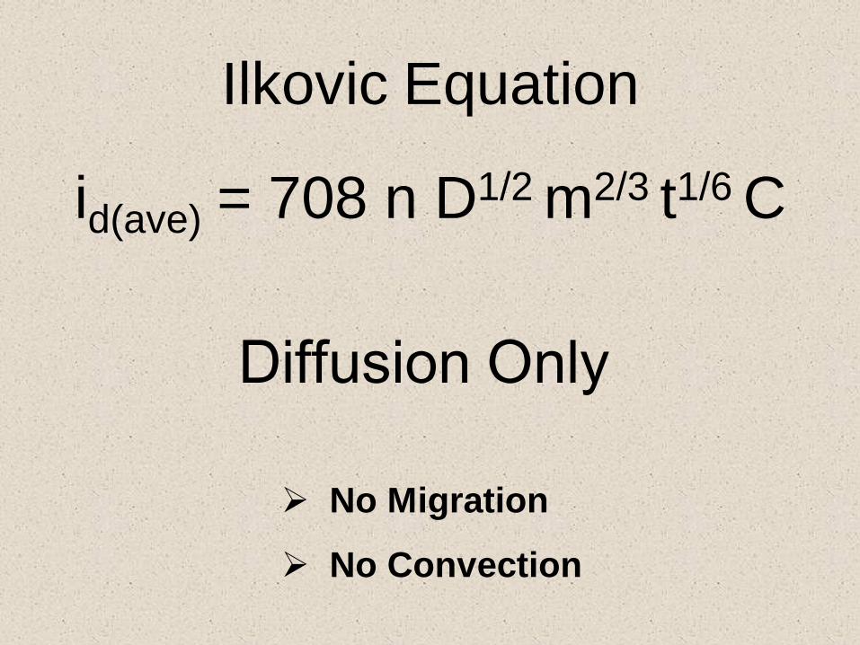
Ilkovic Equation
id(ave) = 708 n D1/2 m2/3 t1/6 C
No Migration
No Convection
Diffusion Only

EFFECT OF DISSOLVED OXYGEN
Prior to apply potential oxygen dissolved in the
test solution must be removed by passing pure
N2 gas through the solution. (N2 purging few
minutes)
Oxygen if not removed undergo reduction /
oxidation at the two potentials -0.1 V and -0.9 V
vs SCE
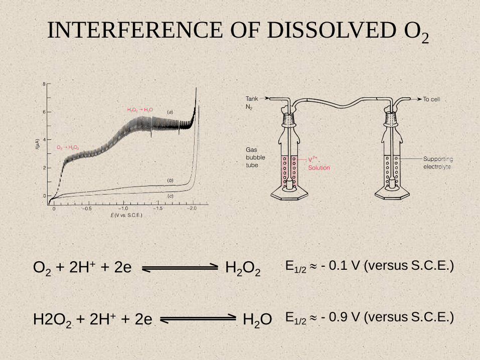
INTERFERENCE OF DISSOLVED O2
O2 + 2H+ + 2e H2O2E1/2 - 0.1 V (versus S.C.E.)
H2O2 + 2H+ + 2e H2O E1/2 - 0.9 V (versus S.C.E.)

LIMITING CURRENT
Its saw toothed shape

SAWTOOTHED SHAPE & GROWTH
OF Hg DROP

Polarograms of 3 mM Pb2+ and 0.25 mM Zn2+ in 2 M
NaOH in the absence of a suppressor and in the presence
of 0.002 wt% Triton X-100
Current Maximum

ANALYTICAL UTILITY
Classical Polarography
a) E1/2 – Identify the Analyte
– In a given matrix an analyte has a characteristic
unique value for E1/2
Note : When matrix change the E1/2 for a given
analyte varies
b) Id C

Analytical uses: (cont‟d)
Measure id for several standards
Concentration of
standards / mg dm-3
Id / A
C1 Id1
C2 Id2
C3 Id3
C4 Id4
C5 Id5
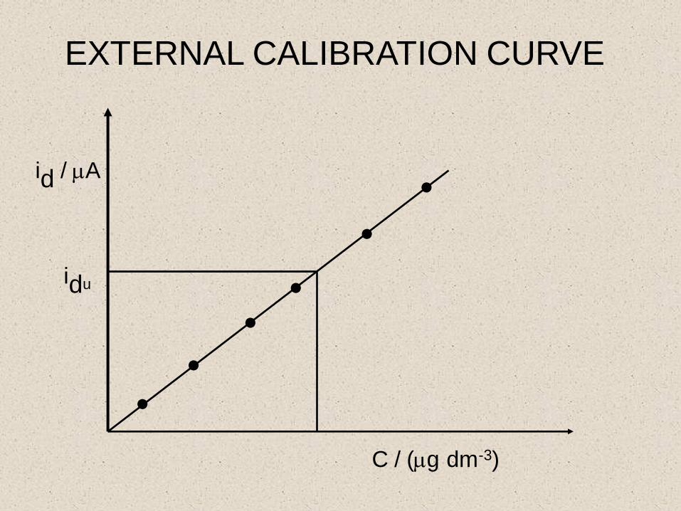
EXTERNAL CALIBRATION CURVE
C / (g dm-3)
id / A
idu
..
.
. ..

STANDARD ADDITION
Al3+ in 0.2 M sodium acetate, pH 4.7, with 0.6 mM
pontachrome violet SW used as a maximum suppressor.

CLASSICAL SHAPE OF A POLAROGRAM
OF A MIXTURE WITH 3 CATIONS
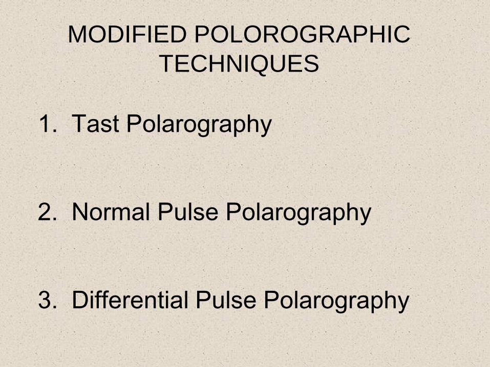
MODIFIED POLOROGRAPHIC
TECHNIQUES
1. Tast Polarography
2. Normal Pulse Polarography
3. Differential Pulse Polarography

4.Squre Wave Plorography
5.Stripping Analysis
6.Linear Sweep Voltammetry
7.Cyclic Voltammetry
With
HMDE

TAST POLAROGRAPHY
PolarogrammPotential ramp
t
V
voltage variations is same as classical polarography
Current measurement only over the last few ms of the
drop life. (Just before it detached)
ADVANTAGE: Precision and accuracy improved.

PULSE POLAROGRAPHY
Normal pulse polarography
Differential pulse polarography
SPECIAL FEACTURES
Working electrode potential is not continuously scanned.
Instead potential is applied in the form of voltage pulses.
NPP uses voltage pulses with progressively increasing
heights .

POTENTIAL RAMP FOR NORMAL PULSE
POLAROGRAPHY

POLAROGRAM (NPP)

DIFFERENTIAL PULSE POLAROGRAPHY
(DPP)

POLAROGRAM (DPP)
Comparison of direct current (D.C.) and differential pulsed polarography (DPP)
of 1.2 x 10⁻⁴ M chlordiazepoxide (the drug Librium) in 3 ml of 0.05 M H2SO4.

LOD (Approx.)
NPP 10-6 mol dm-3
DPP < 10-6 mol dm-3
LOD depends on the type of analyte too.

SQUARE WAVE POLAROGRAPHY
Waveform for square wave polarography. Typical parameters are pulse potential (Ep) = 25
mV, step height (Es) = 10 mV, and pulse period () = 5 ms.

SQUARE WAVE VOLTAMMOGRAM
Square-wave voltammogram for the electro-reduction of a ferric complex (5 x 10⁻⁴ M)
in aqueous Oxalate buffer; = 33.3 ms, Esw = 30 mV and E = 5 mV.
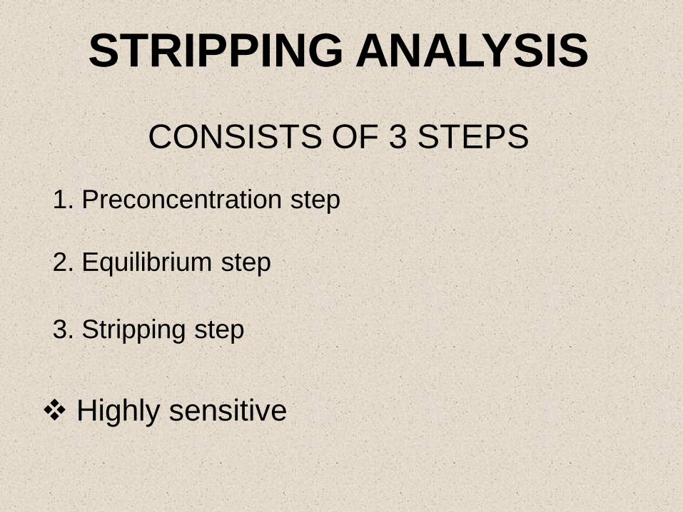
STRIPPING ANALYSIS
CONSISTS OF 3 STEPS
1. Preconcentration step
2. Equilibrium step
3. Stripping step
Highly sensitive

Stripping voltammogram obtained for the determination of Cu(II) in aqueous solution


LINER SWEEP VOLTAMMETRY & CYCLIC
VOLTAMMETRY AT SOLID ELECTRODES
SOLID ELECTRODES
Gold
Platinum
Silver
Carbon
Glassy Carbon (GC)
Pyrolytic Graphite (PG)
Carbon Paste Electrode (CPC)
Hanging Mercury Drop Electrode (HMDE) is also
used in Voltammetry

E
Time
1
2
3
4
4 > 3 > 2 > 4
1
2
3
4
E vs SCE
ip
Ep
= Scan rate
Normally 5 mV / s – 100 mV / s

Linear sweep voltammetry of butylated hydroxyanisole in 0.12
M H{SO in ethanol / benzene

RANDLES-SEVCIK EQUATION
Ip = 0.4463 n F A( ) D1/2 1/2 CnF
RT
Where,
Ip = peak current (A)
n = # of electrons per molecule / ion
F = Faraday constant
A = area of the electrode (cm2)
T = absolute temperature (K)
D = Diffusion coefficient (cm2 /s)
= scan rate (mV / s)
C = concentration (mmol / dm3)

CALIBRATION CURVE OF Ip AGAINST
CONCENTRATION
Ip
Concentration of analyte
Non faradic compartment

CYCLIC VOLTAMMETRY
E
time
Potential applied at „WE‟

CYCLIC VOLTAMMOGRAM

APPLICATION OF CV
More diagnostic studies than analytical
applications
eg: Determination of electrochemical reversibility
i.e. Reduction and Oxidation occur reversibly
Electron transfer process is very fast

DIAGNOSTIC TESTS WITH CV FOR
ELECTROCHEMICAL REVERSIBILITY
1. Ipc = Ipa
2. The peak peak potentials, Epc and Epa, are
independent of the scan rate
3. E0‟ is positioned midway between Epc and
Epa, so Eo‟ = (Epa + Epc) / 2
4. E0‟ is proportional to 1/2
5. The separation between Epc and Epa is
59 mV/n for an n-electron couple

C60 (Buckminsterfullerene) (b) Cyclic voltammogram and (c) differential
pulse polarogram of 0.8 M C60 in acetonitrile /
toluene solution at -10 oC with (n-
C4H9)4N+PF6
- supporting electrolyte

ELECTROCHEMICAL DETECTION LIMITS
FOR SEVERAL POLAROGRAPHIC
METHODS
TECHNIQUE LOWER DETECTION
LIMITS (mol dm-3)
Classical polarography 5 x 10⁻³
Sampled DC polarography 1 x 10⁻⁵
Normal pulse polarography 10-7 - 10-8
Differential pulse polarography 10-8 – 5 x 10⁻⁸
Square-wave polarography 1 x 10⁻⁸
Anodic stripping voltammetry 10-10 - 10-11

VOLTAMMETRY UNDER CONVECTION
CONTROL
Rate of convection is made faster
Diffusion also occurs
No migration
Convection >> Diffusion >> Migration
HYDRODYNAMIC
VOLTAMMETRY
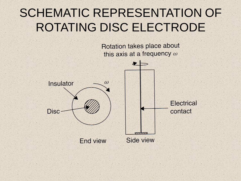
SCHEMATIC REPRESENTATION OF
ROTATING DISC ELECTRODE

SCHEMATIC REPRESENTATION OF
FLUID FLOW AT RDE

Ilim = 0.620 n F A D2/3 -1/6 1/2 C
Where, Ilim = limiting current (A)
n = # of electrons per molecule / ion
F = Faraday constant
A = area of the electrode (cm2)
D = Diffusion Constant (cm2s-1)
= Angular frequency of RDE
= kinematic viscosity of the solution (cm3s-1)
C = concentration (mmol / dm3)
LEVICH EQUVATION
FOR RDE

Voltammograms at a gold RDE, of current density i as a function of potential E (vs. SCE)
and rotation speed f, obtained for a solution of ferrocyanide and ferricyanide ( both at 10
mmol dm-3) in 0.5 mol dm-3 KCl): (a) 20; (b) 15; (c) 10; (d) 5 Hz.
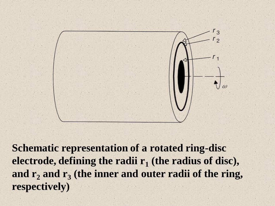
Schematic representation of a rotated ring-disc
electrode, defining the radii r1 (the radius of disc),
and r2 and r3 (the inner and outer radii of the ring,
respectively)

Schematic representation of a typical flow cell used for electroanalytical measurements.
Note the way counter electrode (CE) is positioned downstream, i.e. the product from the
CE flow away from the working electrode
A FLOW CELL

Schematic representation of a typical channel electrode system used for electroanalytical
measurements. The counter electrode is positioned downstream in order to stop the
products from the CE flowing over the working electrode (WE). The reference electrode
is positioned over the WE.
A CHANNEL ELECTRODE

RELATIONSHIP BETWEEN THE LIMITING CURRENT
AND VARIOUS CONVECTIVE PARAMETERS FOR A
NUMBER OF ELECTRODE TYPE
System Equation
Rotated disc
electrode
Ilim = 0.620 nFAD2/3-1/61/2C
Flow cell with a
tubular electrode
Ilim = 5.43 nFD2/3x2/3V1/3C
Flat channel
electrode Ilim = 1.165 nFD2/3( )wX2/3C
Wall-jet
electrode
Ilim = 1.59knFAD2/3-5/12a1/2r3/4Vf3/4C
Vf
H2/d

REFERENCES
1) Quantitative chemical analysis, Daniel C. Harris,
W.H. Freeman & Co.
2) Fundamentals of electroanalytical chemistry, Paul
M.S. Monk (Wiley)
3) Analytical Electrochemistry, Joseph Wang.
4) Electrochemical Methods, Fundamentals &
Applications, Allen J. Bard & Larry R. Falkner (Wiley)

5) Laboratory Techniques in Electroanalytical
Chemistry edited by Peter T. Kissinger & William R.
Heinemen
6) Morden Techniques in Electroanalysis, Peter
Vangsek
7) Electroanalysis: Theory and Application in Aqueous
and Non-Aqueous Media and in Automated Chemical
Control (Technqs and Instrumentation in Analytical)
E.A.M.F. Dahmen

SUPPLIERS OF ELECTROCHEMICAL
INSTRUMENTATION
1)EG & G INSTRUMENTS
Princeton Applied Research, USA
2) Bioanalytical Systems , USA
3) Chi Instruments , Electro chemical work station
France
4) Metrohm Electro Chemical Instruments
Switzerland