poe++ presenttation for bicsi 2016 upload in website
TRANSCRIPT

Challenges in ICT POE++ Design
Radhakrishnan GopalRCDD/ NTS; RPEQ ; MIE Aust CPEng NER
AECOM, [email protected]
BICSI Conference - Dubai 2016

Background
AECOM’s team > 85,000 people• Architects, engineers, scientists , PM• Trusted advisors to clients with projects in 152 countries
AECOM in the Middle East :• More than 60 years• Team of > 4,500 professionals• Buildings, transportation, infrastructure, water and urban developments.• UAE, Qatar, Oman, Kuwait, Saudi Arabia, Bahrain, Lebanon, Egypt, Jordan,
Iraq and Yemen• Team backed by AECOM’s global resources• Always look for talent• www.aecom.com
2

Challenges in ICT POE++ Design
• Introduction• POE• How it works• Standards comparison• Design challenges & recommendations• Takeaway
3

What is PoE?• Power over Ethernet (PoE) - any system that safely pass electrical power
along with data to remote devices in an Ethernet network.
• High availability for data with power• Uninterrupted services• Faster deployment• Convenient• Possibly reduce CAPEX/OPEX• Sustainable
• USB
4

IEEE PoE Standards
5
• IEEE standard: 2003(IEEE 802.3af) – PoE, Type 1
• IEEE revised standard: 2009(IEEE 802.3at) – PoE+, Type 2
• IEEE standard : 2016/2017(IEEE 802.3bt), PoE++, Type 3, 4

Other PoE Standards
• TIA TSB – 184 A, temp increase < 10°C
• HDBase T- Alliance/CE – Compressed HD Video/ Audio, 10Gb/s, 100W
• ISO/IEC TR-29125 & CENELEC TR 50174-99-1-int cabling guidelines forPOE++
• Technology first Developed by CISCO in 2000 to support IP Telephonydeployments
6

PoE Components
Types of devices used in a PoE environment
• PSE (Power Sourcing Equipment): devicethat sends power and data to PD
– End span PSE – located at the end ofa link segment
– Mid span PSE – located in the middleof a link segment, (Power injector)
• PD (Powered Device)
7

PoE Components - PD
• Powered Device (PD), a device that draws power and receives data from aPSE
8
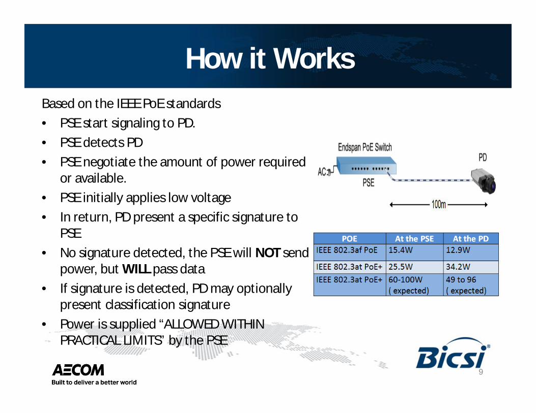
How it WorksBased on the IEEE PoE standards• PSE start signaling to PD.• PSE detects PD• PSE negotiate the amount of power required
or available.• PSE initially applies low voltage• In return, PD present a specific signature to
PSE• No signature detected, the PSE will NOT send
power, but WILL pass data• If signature is detected, PD may optionally
present classification signature• Power is supplied “ALLOWED WITHIN
PRACTICAL LIMITS” by the PSE
9

Class 2 PowerClass 2 Power• Defined within National Electrical Code (NFPA 70)• 30VAC, 60VDC, 100VA• Considered safe from a fire initiation standpoint• Class 2 and 3 systems do not require the same wiring
methods as power, light, and Class 1 systems• There are cases when separation is required between
these systems.• Draft NEC 2017 is under development; “Premises
Powering of Communications Equipment overCommunications Cables”
10

SELV Power
Safety (or Separated) Extra Low Voltage Power (SELV)consists of following:
• For IT equipment, defined in IEC 60950-1
• Extra Low Voltage Circuit (< 35 VAC, <60VDC)
11

Applications of PoE
12
• Health care• Military• Commercial• Security• BMS• ITS• Rail systems• SCADA• Retail• Banking• Residential• Justice• Education• Lighting

TransmissionIEEE 802.3:Ethernet over Twisted Pair cables
802.3 af – PoE
• Min power at PSE output: 15.40 W• Input power to the PD: 13 W (average)• Safe nominal Volts DC: 40 VDC• Maximum current (per pair): 350 mA• Pairs used: 2 pairs each (1,2 & 3,6) for
data and (4,5 & 7,8) for power
13

Transmission cont..IEEE 802.3Ethernet over Twisted Pair cables
802.3 at – PoE+
• Min power at PSE output: 30 W• Input power to the PD: 25.5 W (average)• Safe nominal Volts DC: 53 VDC• Maximum current (per pair): 600mA• Pairs used: 4 pairs for data; 2 pairs (4,5 &
7,8) for both data and power
14

Transmission cont..IEEE 802.3Ethernet over Twisted Pair cables
802.3 bt – PoE++ or 4 Pair POE ( 4PPOE)
• Min power at PSE output: 100 W• Input power to the PD: 49W (type3 and
96W type 4)• Safe nominal Volts DC: TBA• Maximum current (per pair): 600mA to
1000mA• Pairs used: All 4 pairs for both data and
power
15

Comparison
16

Comparison – cont..
17

Challenges – Temp Rise
What Contributes to heat generation?
• Bundle size ( loose lay)• Power source• Ambient air temperature• Environmental conditions• Type of pathways• Number of energized
conductors/pairs• Cable type
18

Challenges – Temp Rise
• IEEE combined with TIA and ISOstandard bodies
• TIA developed profiles for Cat5e, 6, 6AUTP in 100 cable bundles
• ISO data was corroborated• Found Cat5e had the worst heat
dissipation performance & temp rise• Hence Cat5 excluded from study• Not recommended by TIA for new
install.
IEEE adapted baseline profile of Cat5e asthe worst case for Poe+ application
19
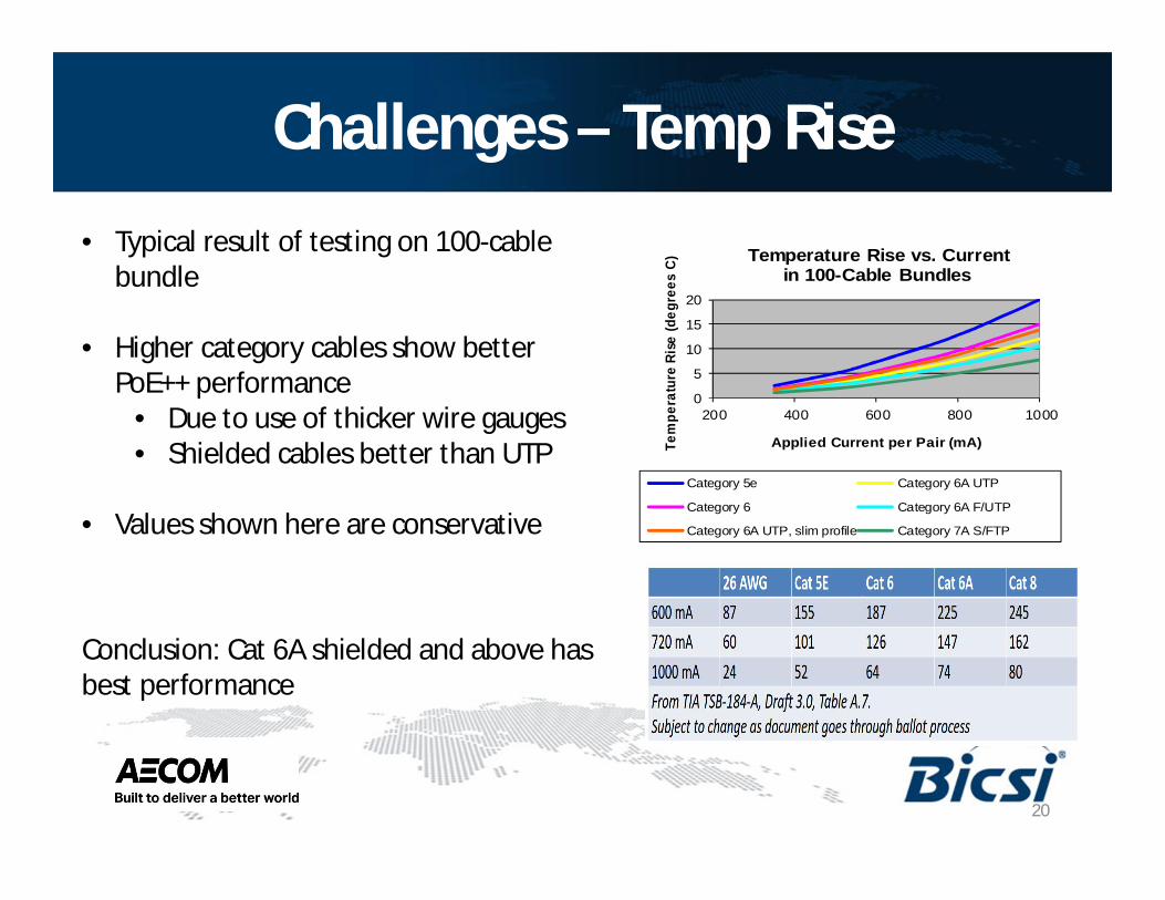
Challenges – Temp Rise• Typical result of testing on 100-cable
bundle
• Higher category cables show betterPoE++ performance
• Due to use of thicker wire gauges• Shielded cables better than UTP
• Values shown here are conservative
Conclusion: Cat 6A shielded and above hasbest performance
0
5
10
15
20
200 400 600 800 1000
Tem
pera
ture
Rise
(deg
rees
C)
Applied Current per Pair (mA)
Temperature Rise vs. Currentin 100-Cable Bundles
Category 5e Category 6A UTP
Category 6 Category 6A F/UTP
Category 6A UTP, slim profile Category 7A S/FTP
20

Dispelling the Myth
Heat dissipation myth
• Screened or fully shielded systemwill “trap” the heat generated byPoE and POE+
• Cat6A, 7A shielded cable offers themost desirable levels of heatdissipation head room and currentdelivery
21

Impact - Derating Length• Higher temp creates additional
insertion loss• Need to de-rate the channel lengths
• Suggest to use vendor headroomwarranties to estimate - Cat7A
22

Challenges – Arching• Device disconnections can’t be anticipated
• When plug is removed from jack “Unmating pairsunder load” produces an arc
• The applied current transitions from flowingthrough conductive metal to air, beforebecoming an open circuit
• Arcing causes corrosion and pitting damage onthe plated contact surface
• TIA standards recommend 50-µm gold /palladium plated tines
• IEC 60512-99-00 specifies a test method @ 100insertions and removals under load conditions of55V DC and 600 mA
23

Eng. Design Considerations
• In POE++, 600mA and above current generate heat in the plant• Excessive temp rise:
– cannot be tested /mitigated in the field– Cause premature aging of jacket material– Increased insertion loss– Create bit errors
• Type and length of cable• Effect of the bundle sizes• Arching• Active equipment
24

Eng. Design Questions to Ask
Apart from all the normal design considerations:
• Is the ambient temperature at least 10°C below cable operating temp?• Are we using the right cable? E.g.: Cat6A shielded or above?• Do I need to de-rate my maximum channel length?• What are the maximum bundle sizes for the cable in use?• Do the connectors meet IEC 60512-99-001?• Are the PSE and PD selected supporting POE+ and are they Poe++ ready?• Are the vendor recommendations followed?• Are the coordination with other design services in place?
25

References / Acknowledgment• PoE plus operating efficiency - How to keep a hot application running cool; and other POE
articles and all graphs and some images - www. Siemon.com;• Inputs from Rajendranath P, Topnet, UAE• Inputs from Betty Bezos, Bezos technology• Inputs Prem Rodrigues, Narender Vasandhani, The Siemon company ltd.• Cisco Universal Power Over Ethernet: Unleash the Power of your Network – White paper• Introduction to PoE and the IEEE802.3af and 802.3at Standards ; Morty Eisen, Marcum
Technology• Inputs from Lawrence McKenna, Wood & Grieve Engineers; www.wge.com.au• Presentation on POE by Frank Straka, Panduit, image slide p.16; www.panduit.com,• PoE and other technologies are pushing powered-device wattages ever-higher; BY Patrick
Mclauglin; Cabling Installation and Maintenance ; Penn Well Corporation• Answering challenges to structured cabling in buildings; Nexans white paper, Jan 2013• www.nfpa.org• Inputs AECOM team• IEEE, TIA standards, various• Linked-in - Slide share, slide p.27• www.Bicsi.org
26

Emerging Technology
• Power over Fiber( POF),tested to 60W in lab
• Witricity (magnetic coupledresonance power transfer)-60W to 30m via magneticfields
27
