pocket money robot - wordpress.com cards wifi ultrasonic radar bluetooth lcds sms phone gyroscopes...
TRANSCRIPT

Revision 2.2 1 Pocket Money Robot
Pocket Money Robot Introduction The Pocket Money Robot (PMR) is a programmable robot buggy based on the Arduino Uno microcontroller board. It is designed to be:
• Cheap
• Easy to build
• Easy to program
• Upgradable
Capability Price Basic robot buggy Programmable to perform pre-set sequences
of movement £16.19
Sonar Sensor Adds basic collision avoidance £0.99 2x Line detector module Adds line following capability £1.89 Sonar Sensor Using 2 sensors adds advanced collision
avoidance £0.99
Display & Pushbuttons Adds controllability & output to the robot £2.68 Light Sensor Adds light seeking/avoiding £1.29 Servo Adds “radar” vision and controlled movement £1.35 Gyro unit Adds directional sense.
ADVANCED – can be used to make a balancing robot
£1.44
As you can see the capabilities of the robot can be extended by adding sensors, a bit at a time and at “pocket money” prices.

Revision 2.2 2 Pocket Money Robot
Pocket Money Robot with added sensors
Once you have got used to programming the Arduino in your robot you can also use it to control many, many other things: LEDs Switches Motors Servos Relays Temperature Sensors Humidity Sensors Light Sensors Remote Controls Real-Time Clocks Speakers Microphones MP3 Players Radio transceivers Ethernet SD cards WiFi Ultrasonic radar Bluetooth LCDs SMS phone gyroscopes inertial sensors RF ID tags, etc. You do not need to know everything about how to control these as there are “Libraries” of “Drivers”, available on the Internet, which you can plug into your program to do a lot of the hard work for you.
Sonar Sensor Module
Line Detector Modules

Revision 2.2 3 Pocket Money Robot
Building the Pocket Money Robot The basic robot consists of the following components
Item Approximate price (inc P&P)
Hyperlink to suggested source
Buggy Kit
£6.99 http://www.banggood.com/buy/Smart-Robot-Car-Chassis-Kit-Speed-Encoder-Battery-Box-For-Arduino.html
Arduino Uno
£2.95 http://www.ebay.co.uk/itm/NEW-ATmega328P-CH340G-UNO-R3-Board-USB-Cable-7-Gilded-Pin-for-Arduino-DIY-GT-/111494292871?pt=LH_DefaultDomain_3&hash=item19f593e587
Arduino Sensor Shield V5.0
£1.62 http://www.ebay.co.uk/itm/Sensor-Shield-Digital-Analog-Module-Servo-Motor-for-Arduino-UNO-R3-MEGA-V5-TU-/121632581204?pt=LH_DefaultDomain_3&hash=item1c51dde654
L9110 Motor Drive Module
£1.54 http://www.ebay.co.uk/itm/L9110S-H-Bridge-Stepper-Motor-Dual-DC-Driver-Controller-Board-Module-for-Arduino-/291054097673?pt=LH_DefaultDomain_3&hash=item43c42d1509
2x Toggle Switch
£0.99 (for 4) http://www.ebay.co.uk/itm/4-Pcs-Blue-AC-125V-6A-3-Pin-SPDT-On-Off-On-3-Position-Mini-Toggle-Switch-CA-/321555515278?pt=LH_DefaultDomain_3&hash=item4ade33c78e
Battery Connector
£0.99 http://www.ebay.co.uk/itm/T-type-Plastic-1pc-9V-DC-Battery-Power-Cable-Clip-Jack-Connector-for-Arduino-/271703576259?pt=LH_DefaultDomain_3&hash=item3f42cb8ec3
Set of Socket-to-socket jumper wires
£0.99 http://www.ebay.co.uk/itm/111483404345?_trksid=p2057872.m2749.l2649&var=410478769978&ssPageName=STRK%3AMEBIDX%3AIT
1x PP3 Alkaline Battery
£2.99 Aldi, Tescos or B&Q have cheap Alkaline batteries
4x AA Alkaline or rechargeable batteries
£2.99 Aldi, Tescos or B&Q have cheap Alkaline batteries

Revision 2.2 4 Pocket Money Robot
Once you have all your bits you can start assembling the robot
1. Do not fit batteries into the Battery Box or the Arduino Battery Connector until all the wiring is finished. You could get a short circuit!
2. Add wires to the motors. Using about 10cm of flexible insulated wire (you can cut the ends off a jumper wire if you have to) strip about 5mm of insulation off one end and twist the wires so they stay tightly together. Find the motor connections and push the bare wires through the connection, bend them back and twist. (If you can get them soldered it makes a better connection) Do this for both connections on both motors.
3. Fit the motor mounting blocks to the motors. Using the long screws (2 per motor),
push them through the holes in the motor and through the holes in the Motor Mounting Blocks, making sure the 2 tapped holes on the small end are uppermost. Fit the nuts and tighten. Do this for the other motor, noting that this is the other way round

Revision 2.2 5 Pocket Money Robot
4. Fit the Wheel Sensor Discs To the motor spindles. First clean-up the Wheel Sensor Discs by poking out any un-released segments with a small screwdriver or pencil point. (note these sensor discs are not used at the moment but can be used with Wheel Speed Sensors to accurately measure distance and/or speed for future projects)
Push the Wheel Sensor Discs onto the motor spindle, note that it is on the same side as the Motor Mounting Block.
5. Fit the Wheels onto the other motor spindles.
6. Secure the wires to the motors. Lay the wires back along the motor and wrap some tape (insulation, masking or Sellotape or zip-tags if you have them) around the motor to hold the wires in place and stop then being pulled off.

Revision 2.2 6 Pocket Money Robot
7. Add sockets and a switch to the Battery Box wires. Peel off one red and one black wire from the jumper wires. Cut the red jumper wire in half and strip off 1cm of insulation from ONE end. Strip off 1cm of insulation from the red Battery Box wire. Fix the battery box red wire to one of the outer switch pins. Fix the cut red jumper wire to the middle switch pin. (If you can get the joints soldered it makes a better connection) Wrap some tape (insulation, masking or Sellotape) around the joints to insulate them. Cut the black jumper wire about 3cm from one end and strip off 1cm of insulation from both ends. Strip off 1cm of insulation from the black Battery Box wire. Wind the three ends together tightly. (If you can get them soldered it makes a better connection) Wrap some tape (insulation, masking or Sellotape) around the joint to insulate it. (This means you have a Battery Box with one red wire socket and two black wire sockets. The short black wire will go to the Motor Drive Module, the long black wire will go to a 0V on the Sensor Shield. See 16. This joins the 0V of the motor supply to the 0V of the Arduino supply without any motor current going through the Arduino which could cause interference)
8. Add a switch to the Arduino power lead. Cut the red wire in the Arduino to PP3 lead in half. Strip off 1cm of insulation from each of the ends. Fix the battery connector red wire to one of the outer switch pins. Fix the Arduino plug wire to the middle switch pin. (If you can get the joints soldered it makes a better connection) Wrap some tape (insulation, masking or Sellotape) around the joints to insulate them. Fit the Motors to the Motor Mounting Blocks
Revision 2.2 7 Pocket Money Robot
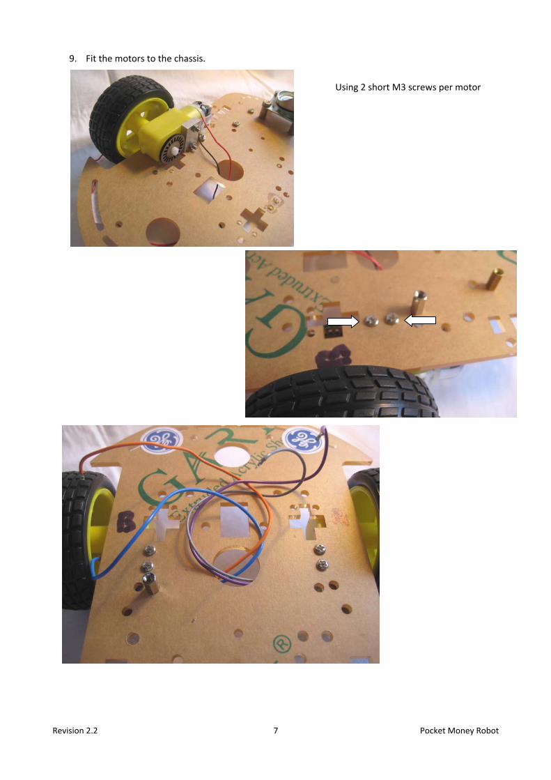
9. Fit the motors to the chassis. Using 2 short M3 screws per motor
Revision 2.2 8 Pocket Money Robot
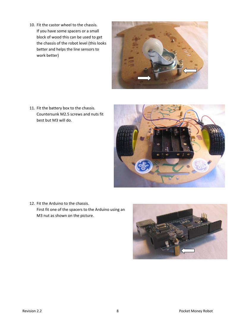
10. Fit the castor wheel to the chassis. If you have some spacers or a small block of wood this can be used to get the chassis of the robot level (this looks better and helps the line sensors to work better)
11. Fit the battery box to the chassis. Countersunk M2.5 screws and nuts fit best but M3 will do.
12. Fit the Arduino to the chassis. First fit one of the spacers to the Arduino using an M3 nut as shown on the picture.

Revision 2.2 9 Pocket Money Robot
Fit 2 spacers to the chassis in the positions shown with the red arrows. Fit one more spacer in the position shown with the green arrow and insulate it with tape as it sits underneath the Arduino. Fit the Arduino onto the spacers using M3 screws at the positions shown.
13. Fit the Motor Drive Module to the chassis. Using an M3 spacer and nut to the chassis and am M3 screw through the Motor Drive Module into the spacer.

Revision 2.2 10 Pocket Money Robot
14. Connect the motor wires to the Motor Drive Module. Right hand motor to Motor-A screw terminals. Left hand motor to Motor-B screw terminals.
15. Fit the Sensor Shield to the top of the Arduino.
16. Wire the battery box to the Sensor Shield and Motor Drive Module. The short black wire goes to the Gnd pin on the Motor Drive Module. The long black wire goes to a 0V on the Sensor Shield. The Red wire goes to the Vcc pin on the Motor Drive Module
17. Using jumper wires make connections between the sensor shield and the Motor Drive Module. Connections listed in Table 1
18. Fit the switches to a handy bit of chassis, Blutack is quite good for this.
19. Check your connections once more (it is worth it)

Revision 2.2 11 Pocket Money Robot
20. Power-up the Arduino for the first time. Check both switches have their toggles on the side that there is a wire on the connection (not the side with an empty terminal). This usually corresponds to the switch being off. Put 4x AA alkaline batteries in the Motor Battery Box. Click one PP3 alkaline battery onto the Arduino Power Lead. FIRST switch on the Arduino power. You should see some LEDs light up on the Arduino. If it has never been programmed one of them should be flashing as this is the default program that is pre-loaded into the Arduino. If you get no lights you will have to check your connections. See the Problems Section for de-bugging help. Switch off the Arduino.
21. Power-up the Motor Drive Module for the first time. Switch on the Motor Power. A LED on the Motor Drive Module should light. If you get no lights you will have to check your connections. See the Problems Section for de-bugging help.
22. Fully power-up the PMR (Pocket Money Robot) Nothing should happen at this point as you have no program loaded into the Arduino. You should have LED(s) lit on the Arduino, Sensor Shield and Motor Drive Module. Switch all power off.

Revision 2.2 12 Pocket Money Robot
Getting the PMR Going 1. Download the Arduino IDE program from the Arduino Website:
http://www.arduino.cc/en/Main/Software
2. Install it. 3. Connect the Arduino to your PC using a USB lead.
If it gives a message “New Hardware Detected… Searching for Drivers… Loading Drivers” wait for it to finish.
4. Start the Arduino IDE program.
In the IDE: Tools menu> Port> check the IDE has found your Arduino Tools menu> Board> select your board (Arduino Uno) (once you have done all this your computer should remember the settings)
5. Test Program 01 We need to load a test program (a program is called a “Sketch” in the Arduino world) into the Arduino to check that the motors are connected the correct way round. In the IDE edit window select everything ([Ctrl]a) Delete it ([Delete]) Now copy the following text and paste it into the IDE edit window:
// PMR Test Program 1// Check connections for Motor A void setup() { pinMode(5,OUTPUT); //speedPinA pinMode(6,OUTPUT); //speedPinB pinMode(7,OUTPUT); //directionPinA pinMode(8,OUTPUT); //directionPinB } void loop() { analogWrite(5,254); //Motor A speed - maximum digitalWrite(7,0); //turn DC Motor A move clockwise analogWrite(6,0); //Motor B Speed - zero digitalWrite(8,0); //turn DC Motor B move clockwise }

Revision 2.2 13 Pocket Money Robot
6. To compile your sketch click the near the top left of the window.
7. Wait for “done compiling” 8. If not check for mistakes
in the program 9. When all OK upload to the
Arduino, click the
10. NOTE If you get a compilation error your probably did not copy ALL of the program or you did not delete everything before you pasted the new program in.
11. When the upload is done, hold your PMR off the ground and turn on the Motor Power. The RIGHT HAND motor (on the right when looking from the back of the robot, forwards) should be going forwards fairly fast. The left hand motor should be stopped. Switch off the motor power.
12. If the motor was going backwards swap over the two wires on the Motor-A screw terminals.
Turn on the Motor Power. The RIGHT HAND motor should now be going forwards fairly fast. Switch off the motor power.
13. Test Program 02
We need to load the next test program In the IDE edit window select everything ([Ctrl]a) Delete it ([Delete]) Now copy the following text and paste it into the IDE edit window:
// PMR Test Program 2 // Check connections for Motor B void setup() { pinMode(5,OUTPUT); //speedPinA pinMode(6,OUTPUT); //speedPinB pinMode(7,OUTPUT); //directionPinA pinMode(8,OUTPUT); //directionPinB } void loop() {

Revision 2.2 14 Pocket Money Robot
analogWrite(5,0); //Motor A speed - zero analogWrite(6,(255-254)); //Motor B Speed - maximum digitalWrite(7,0); //turn DC Motor A move clockwise digitalWrite(8,1); //turn DC Motor B move anticlockwise }
14. To compile and upload sketch click the near the top left of the window. 15. Wait for “done compiling” 16. If not check for mistakes in the program 17. When the upload is done, hold your PMR off the ground and turn on the Motor Power. The LEFT
HAND motor (on the left when looking from the back of the robot, forwards) should be going forwards fairly fast. The right hand motor should be stopped. Switch off the motor power.
18. If the motor was going backwards swap over the two wires on the Motor-B screw terminals.
Turn on the Motor Power. The LEFT HAND motor should now be going forwards fairly fast. Switch off the motor power.
19. Test Program 03
We need to load the next test program In the IDE edit window select everything ([Ctrl]a) Delete it ([Delete]) Now copy ALL the following text and paste it into the IDE edit window:
// PMR Test Program 3 // Check Speed Control of the motors #define MotorADirPin 7 // Pin 7 controls the direction for motor A #define MotorBDirPin 8 // Pin 8 controls the direction for motor B #define MotorASpeedPin 5 // Pin 5 controls the speed for motor A #define MotorBSpeedPin 6 // Pin 6 controls the speed for motor B #define Forward 0 // Define value for Forward on MotornDirPin #define Backward 1 // Define value for Backward on MotornDirPin int SpeedMotorA = 0; // Define variable for Motor A speed, set to 0 int SpeedMotorB = 0; // Define variable for Motor B speed, set to 0 void setup() { pinMode(MotorADirPin, OUTPUT); // sets the pin as output pinMode(MotorBDirPin, OUTPUT); // sets the pin as output pinMode(MotorASpeedPin, OUTPUT); // sets the pin as output pinMode(MotorBSpeedPin, OUTPUT); // sets the pin as output } void loop() { // First Motor A for (SpeedMotorA = 0; SpeedMotorA < 255; SpeedMotorA++) //ramp the speed up { MotorAControl(Forward, SpeedMotorA); Serial.print("SpeedA = " ); Serial.println(SpeedMotorA); delay(10); // wait 0.1 seconds } for (SpeedMotorA = 255; SpeedMotorA > 0; SpeedMotorA--) //ramp the speed down { MotorAControl(Forward, SpeedMotorA); Serial.print("SpeedA = " ); Serial.println(SpeedMotorA); delay(10); // wait 0.1 seconds }

Revision 2.2 15 Pocket Money Robot
for (SpeedMotorA = 0; SpeedMotorA < 255; SpeedMotorA++) //ramp the speed up { MotorAControl(Backward, SpeedMotorA); delay(10); // wait 0.1 seconds } for (SpeedMotorA = 255; SpeedMotorA > 0; SpeedMotorA--) //ramp the speed down { MotorAControl(Backward, SpeedMotorA); delay(10); // wait 0.1 seconds } // Now Motor B for (SpeedMotorB = 0; SpeedMotorB < 255; SpeedMotorB++) //ramp the speed up { MotorBControl(Forward, SpeedMotorB); delay(10); // wait 0.1 seconds } for (SpeedMotorB = 255; SpeedMotorB > 0; SpeedMotorB--) //ramp the speed down { MotorBControl(Forward, SpeedMotorB); delay(10); // wait 0.1 seconds } for (SpeedMotorB = 0; SpeedMotorB < 255; SpeedMotorB++) //ramp the speed up { MotorBControl(Backward, SpeedMotorB); delay(10); // wait 0.1 seconds } for (SpeedMotorB = 255; SpeedMotorB > 0; SpeedMotorB--) //ramp the speed down { MotorBControl(Backward, SpeedMotorB); delay(10); // wait 0.1 seconds } } // ------- Subroutines to control motors ------------------------------------------------- void MotorAControl(int Direction, int Speed) { digitalWrite(MotorADirPin, Direction); // set motor A direction if (Direction == Forward){ // if Forward analogWrite(MotorASpeedPin, Speed); // normal PWM } else { analogWrite(MotorASpeedPin, (255-Speed)); // in reverse pulses are upside down } } void MotorBControl(int Direction, int Speed) { if (Direction == Forward){ // if Forward Direction = Backward; // flip direction for motor B as it is mounted the other way to Motor A digitalWrite(MotorBDirPin, Direction); // set motor B direction analogWrite(MotorBSpeedPin, (255-Speed)); // in reverse pulses are upside down } else { // is Backward Direction = Forward; // flip direction for motor B as it is mounted the other way to Motor A digitalWrite(MotorBDirPin, Direction); // set motor B direction analogWrite(MotorBSpeedPin, Speed); // normal PWM } }
20. To compile and upload sketch click the near the top left of the window. 21. Wait for “done compiling” 22. If not check for mistakes in copying the program

Revision 2.2 16 Pocket Money Robot
23. When the upload is done, hold your PMR off the ground and turn on the Motor Power. The right hand motor should start slowly, ramp up to full forward speed then ramp down and stop, then start in reverse slowly, ramp up to full reverse speed then ramp down and stop. Then the left hand motor should start slowly, ramp up to full forward speed then ramp down and stop, then start in reverse slowly, ramp up to full reverse speed then ramp down and stop. Switch off the motor power.
24. If the motors do not start slow then ramp up to fast, the connections between the Arduino and the
Motor Control Module are probably wrong. 25. Disconnect the USB cable from the Arduino.
Put your PMR on the floor Switch on the Motor Power Switch on the Arduino power The PMR should now turn to the left using the right hand wheel, stop then turn to the right. Then PMR should turn to the right using the left hand wheel, stop then turn to the left. Switch off the motor power.
26. You have now checked out the motor control for the PMR.
Revision 2.2 17 Pocket Money Robot
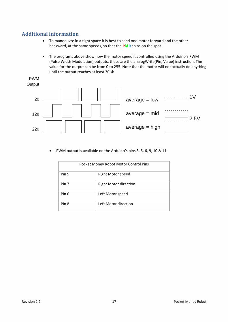
average = low average = mid average = high
1V
2.5V
PWM Output
20
128
220
Additional information • To manoeuvre in a tight space it is best to send one motor forward and the other
backward, at the same speeds, so that the PMR spins on the spot.
• The programs above show how the motor speed it controlled using the Arduino’s PWM (Pulse Width Modulation) outputs, these are the analogWrite(Pin, Value) instruction. The value for the output can be from 0 to 255. Note that the motor will not actually do anything until the output reaches at least 30ish. • PWM output is available on the Arduino’s pins 3, 5, 6, 9, 10 & 11.
Pocket Money Robot Motor Control Pins
Pin 5 Right Motor speed
Pin 7 Right Motor direction
Pin 6 Left Motor speed
Pin 8 Left Motor direction

Revision 2.2 18 Pocket Money Robot
M
+V
-V
A
C D
B
H-Bridge
M
+V
-V
A
C D
B
M
+V
-V
A
C D
B
-V -V
+V Forwards
A and D on
Backwards
B and C on
• The Motor Control Module uses 2 H-Bridge drive ICs. These convert the low-power
signals from the Arduino to higher power signals, capable of driving motors. They have 4 power switches in an H pattern. Current can be fed through the motor in both directions In this example switches A and C are controlled by the PWM output e.g. Pin 5, switches B and D are controlled by the direction output e.g. Pin 7. When output Pin 7 is low (forward), switch-D is ON (& switch-B is off), pulsing output Pin 5 high pulses on switch-A to send pulses of current through the motor forward. When output Pin 7 is high (backward), switch-B is ON (& switch-D is off), pulsing output Pin 5 low pulses on switch-C to send pulses of current through the motor backward.

Revision 2.2 19 Pocket Money Robot
Connections for the Basic Robot
Basic Programmable Robot Connections Arduino Sensor Shield Pin Motor Drive Pin Motor A Speed Row S Pin 5 A-1A Motor A Direction Row S Pin 7 A-1B Motor B Speed Row S Pin 6 B-1A Motor B Direction Row S Pin 8 B-1B Black (0V) from motor battery
Row G Pin 5 (any row G pin) GND
Red +6V from motor battery & switch
No Connection VCC
Table 1: Basic PMR Connections
Using Blockly you can select a direction and a time for the motors to run. By building up a sequence of moves you can program the robot to go where you want.

Revision 2.2 20 Pocket Money Robot
Connections for the Line Following Robot
Line Following Robot Connections Arduino Sensor Shield Pin Motor Drive Pin
Motor A Speed Row S Pin 5 A-1A Motor A Direction Row S Pin 7 A-1B Motor B Speed Row S Pin 6 B-1A Motor B Direction Row S Pin 8 B-1B Black (0V) from motor battery
Row G Pin 5 (any row G pin) GND
Red +6V from motor battery & switch
No Connection VCC
Right Line Sensor Pin Right Side Line Sensor Signal Row S Pin A0 Out Right Side Line Sensor +5V Row V Pin A0 VCC Right Side Line Sensor 0V Row G Pin A0 GND Left Line Sensor Pin Left Side Line Sensor Signal Row S Pin A1 Out Left Side Line Sensor +5V Row V Pin A1 VCC Left Side Line Sensor 0V Row G Pin A1 GND
Using Blockly you can use a control-decision based on the inputs from the Line Sensors to select the direction and control the motors so that the robot follows the black line.

Revision 2.2 21 Pocket Money Robot
Connections for the Sonar-Radar Robot
Sonar-Radar Robot Connections Arduino Sensor Shield Pin Motor Drive Pin
Motor A Speed Row S Pin 5 A-1A Motor A Direction Row S Pin 7 A-1B Motor B Speed Row S Pin 6 B-1A Motor B Direction Row S Pin 8 B-1B Black (0V) from motor battery
Row G Pin 5 (any row G pin) GND
Red +6V from motor battery & switch
No Connection VCC
Sonar Module Sonar ModuleTrigger Row S Pin A2 Trig Right Side Line Sensor +5V Row V Pin A2 VCC Right Side Line Sensor 0V Row G Pin A2 GND Sonar Module Echo Row S Pin A3 Echo
Using Blockly you can use a control-decision based on the input from the Sonar Module to control the motors so that the robot does not collide with anything.

Revision 2.2 22 Pocket Money Robot
Connections for the Advanced Sonar-Radar Robot
Advanced Sonar-Radar Robot Connections Arduino Sensor Shield Pin Motor Drive Pin
Motor A Speed Row S Pin 5 A-1A Motor A Direction Row S Pin 7 A-1B Motor B Speed Row S Pin 6 B-1A Motor B Direction Row S Pin 8 B-1B Black (0V) from motor battery
Row G Pin 5 (any row G pin) GND
Red +6V from motor battery & switch
No Connection VCC
Right Sonar Module Sonar Module Trigger Row S Pin A2 Trig Right Side Line Sensor +5V Row V Pin A2 VCC Right Side Line Sensor 0V Row G Pin A2 GND Sonar Module Echo Row S Pin A3 Echo Left Sonar Module Sonar Module Trigger Row S Pin A4 Trig Right Side Line Sensor +5V Row V Pin A4 VCC Right Side Line Sensor 0V Row G Pin A4 GND Sonar Module Echo Row S Pin A5 Echo
Using Blockly you can use a control-decisions based on the inputs from the two Sonar Modules to control the motors so that the robot veers away from obstacles and does not collide with anything.
Further experiments. Add a Sonar Module to the Line Following Robot so that it will stop if an obstacle blocks its path.
Try programming the robot without Blockly by writing the code in the Arduino IDE program. It probably would be best to start with a Blockly generated program and try adding extra bits on. You can add far more complexity to your robots behaviour by using the Arduino language directly