pn 750-0075-005 surgeban - power & systems innovations manual.pdf · pn 750-0075-005 joslyn ......
TRANSCRIPT

Surge
Ban
Installation, Operationand Maintenance ManualPN 750-0075-005
JOSLYN® SURGEBAN™ INSTALLATION, OPERATION AND MAINTENANCE MANUAL
SurgeBan
T H E # 1 N A M E I N S U R G E S U P P R E S S I O N
TransientSuppressionSystems
™
Your Guide to Installation
Pre-Installation Checklist
Installation Methods for Common Service Configurations
Single-Phase, 2-Wire
Split-Phase, 3-Wire
3-Phase, 4-Wire WYE
3-Phase, 3-Wire (2 Sides of WYE)
3-Phase, 3-Wire DELTA
3-Phase, 2-Wire (2 Sides of DELTA)
3-Phase, 3-Wire Corner-Grounded DELTA
3-Phase, 4-Wire High-Leg DELTA
Plan Your Installation
Conductor Routing
Conductor Sizing
Conduit Openings
Mounting
Enclosure Dimensions
Monitoring Options
Electrical Connections
Connecting Form C Dry Contacts
Before Applying Power
Verifying Proper Operation
Troubleshooting
Module Replacement Procedure
Technical Assistance
Returns and Warranty Procedures
Warranty Statement
Index
JOSLYN® SURGEBAN™ INSTALLATION, OPERATION AND MAINTENANCE MANUAL2
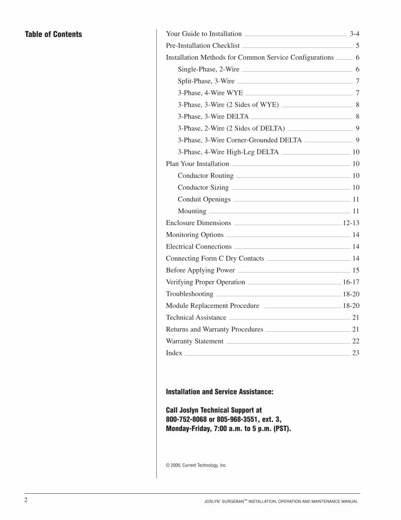
Table of Contents
© 2000, Current Technology, Inc.
3-4
5
6
6
7
7
8
8
9
9
10
10
10
10
11
11
12-13
14
14
14
15
16-17
18-20
21
21
22
23
Installation and Service Assistance:
Call Joslyn Technical Support at 800-752-8068 or 805-968-3551, ext. 3, Monday-Friday, 7:00 a.m. to 5 p.m. (PST).
18-20

JOSLYN® SURGEBAN™ INSTALLATION, OPERATION AND MAINTENANCE MANUAL 3
Today’s sophisticated electronic equipment requires reliable, sup-pression filter systems. By selecting Joslyn® SurgeBan™ devices,you have taken a critical step toward decreasing downtime andensuring longer product life for your equipment.
The SurgeBan Transient Suppression System connects to yourelectrical distribution system to protect sensitive electrical andelectronic equipment against the harmful effects of lightningstrikes, induced transients on AC power lines, internally generat-ed transients and high-frequency noise. SurgeBan fulfills the single-pulse surge current capacity testing recommendations perNEMA LS1-1992, paragraphs 2.2.9 and 3.9.
SurgeBan provides advanced surge protection and filtering tech-nology. Created for optimum reliability and flexibility, SurgeBanoffers unrivaled protection and features in a modular, building-block design with a choice of four types of suppression modules:‘JM’ 50kA Metal Oxide Varistor (MOV); 100kA MOV; ‘JS’Silicon Avalanche Diode (SAD); and ‘JC’ High-Frequency Filter.This innovative modularity allows simple and quick maintenanceprocedures should a module need to be replaced. Each suppres-sion and filter module has an at-a-glance, bicolor status light(green = healthy and red = fault) to confirm the individual elements of the suppressor system are functioning properly.
In addition, each module has a keyed mounting as well as color-coded labels to ensure correct module replacement:
Orange 50 kA MOV
Red 100 kA MOV
Purple 10 kA SAD
Green Filter
SurgeBan’s unique design provides true, fail-safe protection. An individual thermal cut-off on each MOV and SAD protectsagainst temporary overvoltage, limited short circuit current conditions and ensures clean end-of-life performance. Both 50kAand 100kA MOV modules have 20kA backup MOVs to providecontinuous protection.
SurgeBan offers a full range of monitoring options. Choicesrange from the basic commercial-power and suppressor-statusindicator lights, to the full-featured package featuring Form C dryrelay contacts, audible alarm with disable switch and surge eventcounter.
SurgeBan’s robust NEMA 4/4X enclosure allows installation inoutdoor and corrosive environments.
Your Installation Guide to the SurgeBan™ Transient Suppression System
Color stripes on front and side indicate module type. For example, 100kA MOV modules have red stripes.
STRIPE COLOR MODULE TYPE
JOSLYN® SURGEBAN™ INSTALLATION, OPERATION AND MAINTENANCE MANUAL4
Monday through Friday, 7:00 a.m. to 5:00 a.m. (PST)800-752-8068 or 805-968-3551 ext. 3
10-Year Limited Warranty: Joslyn SurgeBan products are warranted for a period of 10 years from date of shipment. AFive-Year Extended Warranty is available for a total of 15 yearscoverage.
The Joslyn® SurgeBan™ has filed for United States patent protec-tion for the technology incorporated in the SurgeBan product.Should such patents subsequently issue, Current Technology, Inc.will enforce and protect its patent rights as provided by Section35 USC.
This manual provides installation guidelines for SurgeBan prod-ucts. Proper product selection and compliance with these guide-lines will help your new suppression system provide years of reli-able service. If installers are unsure about the facility’s electricalconfiguration or have other installation-related questions, theyshould consult a master electrician or other qualified electricalprofessional.
When shortcuts take the place of proper installation procedures,the SurgeBan system may be damaged or may not provide adequate protection. Improper installation may also void the warranty. It is extremely important to follow these installationprocedures carefully.
This manual is designed to guide you through the procedure of installing the SurgeBan product and connecting it to your electrical system. If you have any questions about how to installSurgeBan, please call Joslyn Technical Support at 800-752-8068or 805-968-3551, ext. 3.
Installation Assistance
Ten-Year Limited and Five-Year Extended Warranty
The Importance of CorrectInstallation
Patent Notice

WARNING! SurgeBan’s warranty is void if the unit is damaged asa result of improper installation or failure to verify the followingconditions prior to installation.
WARNING! Discontinue installation if (1) your conditions areinconsistent with the checklist below or (2) your conditions can-not be verified. Call Joslyn Products Technical Support at 800-752-8068 or 805-968-3551, ext. 3 if you have questions.
Before BeginningConfirm that the voltage(s) and service configuration shown onthe SurgeBan product label are consistent with the voltage andservice configuration of the facility. A model number is on thelabel inside the SurgeBan door. Each model number correspondsto the voltage and service configurations printed in the tablebelow:
Example of a suppressor model number: SBM100-120/240-2A6B
SBxxxx-120-1xxx 120VAC, 1-phase, 2-wire + ground
SBxxxx-127-1xxx 127VAC, 1-phase, 2-wire + ground
SBxxxx-120/240-2xxx 120/240VAC, split-phase, 3-wire + ground
SBxxxx-208/120-3xxx 208/120VAC, 3-phase WYE, 4-wire + ground
SBxxxx-220/127-3xxx 20/127VAC, 3-phase WYE, 4-wire + ground
SBxxxx-230-1xxx 230VAC, 1-phase, 2-wire + ground
SBxxxx-240-5xxx 240VAC 3-phase ungrounded DELTA, 3-wire + ground
SBxxxx-240/120-7xxx 240/120VAC, 3-phase high-leg DELTA, 4-wire + ground(B phase must be 208V)
SBxxxx-277-1xxx 277VAC, 1-phase, 2-wire + ground
SBxxxx-400-5xxx 400VAC 3-phase ungrounded DELTA, 3-wire + ground
SBxxxx-400/230-3xxx 400/230VAC, 3-phase WYE, 4-wire + ground
SBxxxx-480-5xxx 480VAC 3-phase ungrounded DELTA, 3-wire + ground
SBxxxx-480/277-3xxx 480/277VAC, 3-phase WYE, 4-wire + ground
WARNING! Check to ensure that a proper Xo bond is installedbetween the neutral and ground terminals at the transformerupstream from all 3-phase WYE, 3-phase high-leg DELTA orsplit-phase SurgeBan devices (see NEC article 250). If the transformer is not accessible, check the main service disconnect/panel for the N-G bond. Lack of a proper bond willdamage SurgeBan and void the warranty.
JOSLYN® SURGEBAN™ INSTALLATION, OPERATION AND MAINTENANCE MANUAL 5
Pre-Installation Checklist
W A R N I N G !
Product Label Designation System Voltage, Service Configuration
W A R N I N G !

JOSLYN® SURGEBAN™ INSTALLATION, OPERATION AND MAINTENANCE MANUAL6
Confirm that the environmental conditions are consistent with thefollowing ranges:
• Ambient temperatures: SurgeBan must be installed in an area with a temperature between –40º and +160º F (–40º and 70º C).
• Humidity: SurgeBan must be installed in an area with relativehumidity between 5 percent and 95 percent non-condensing.
• Altitude: SurgeBan must be installed in an altitude below16,000 feet (5,000 m).
SurgeBan must be connected in parallel with the electrical sys-tem. It must be connected to an overcurrent protection device(circuit breaker or fused switch) rated 200A maximum. If thesuppressor is connected to a dedicated overcurrent protectiondevice, it needs to be rated at 60A minimum. The advantage ofusing a dedicated overcurrent protection device for the suppressor(even if the upstream breaker is 200A or less) is that it allows thesuppressor to be de-energized during service without disturbingthe electrical service to the rest of the facility.
• Do not connect SurgeBan to the line side of the main servicebreaker or disconnecting means.
• Do not install SurgeBan where the available short-circuit currentto the SurgeBan unit is more than 100,000A RMS symmetrical amperes at 480VAC.
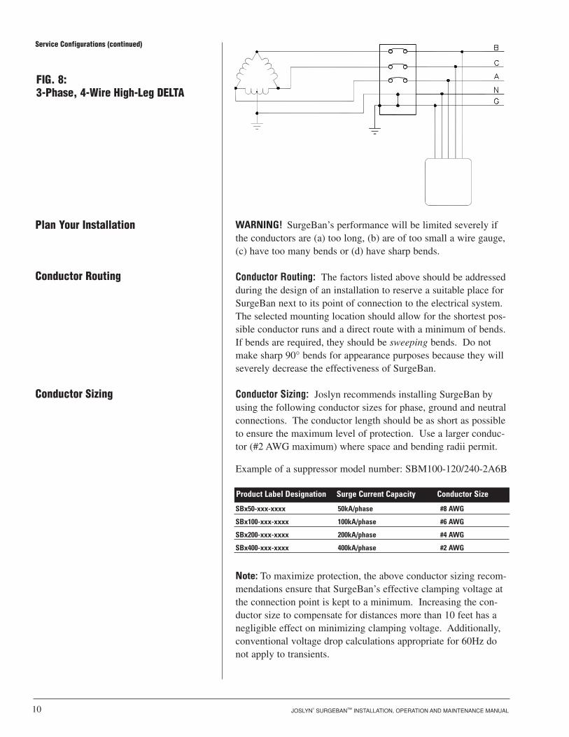
Figures 1–8 show the electrical relationship between SurgeBanand these eight basic service configurations: Single-phase, 2-Wire; Split Single-phase, 3-Wire; 3-phase, 4-Wire WYE; 3-phase, 3-Wire (2 sides of WYE); 3-phase, 3-Wire DELTA; 3-phase, 2 Wire (2 sides of DELTA); 3-phase, 3-Wire Corner-grounded DELTA; and 3-phase, 4-Wire High-leg DELTA.
Installation Methods forCommon Service Configurationsfor the Design Engineer andthe Installer
Service Configurations
FIG. 1: Single-Phase, 2-Wire

JOSLYN® SURGEBAN™ INSTALLATION, OPERATION AND MAINTENANCE MANUAL 7
FIG. 2: Split-Phase, 3-Wire
FIG. 3:3-Phase, 4-Wire WYE
Service Configurations (continued)
N
G
L2
L1

FIG. 4: 3-Phase, 3-Wire(2-Sides of WYE)
FIG. 5:3-Phase, 3-Wire DELTA
Service Configurations (continued)
JOSLYN® SURGEBAN™ INSTALLATION, OPERATION AND MAINTENANCE MANUAL8

JOSLYN® SURGEBAN™ INSTALLATION, OPERATION AND MAINTENANCE MANUAL 9
FIG. 6:3-Phase, 2-Wire (2-Sides of DELTA)
FIG. 7:3-Phase, 3-Wire Corner-GroundedDELTA
Service Configurations (continued)
JOSLYN® SURGEBAN™ INSTALLATION, OPERATION AND MAINTENANCE MANUAL10
WARNING! SurgeBan’s performance will be limited severely ifthe conductors are (a) too long, (b) are of too small a wire gauge,(c) have too many bends or (d) have sharp bends.
Conductor Routing: The factors listed above should be addressedduring the design of an installation to reserve a suitable place forSurgeBan next to its point of connection to the electrical system.The selected mounting location should allow for the shortest pos-sible conductor runs and a direct route with a minimum of bends.If bends are required, they should be sweeping bends. Do notmake sharp 90° bends for appearance purposes because they willseverely decrease the effectiveness of SurgeBan.
Conductor Sizing: Joslyn recommends installing SurgeBan byusing the following conductor sizes for phase, ground and neutralconnections. The conductor length should be as short as possibleto ensure the maximum level of protection. Use a larger conduc-tor (#2 AWG maximum) where space and bending radii permit.
Example of a suppressor model number: SBM100-120/240-2A6B
SBx50-xxx-xxxx 50kA/phase #8 AWG
SBx100-xxx-xxxx 100kA/phase #6 AWG
SBx200-xxx-xxxx 200kA/phase #4 AWG
SBx400-xxx-xxxx 400kA/phase #2 AWG
Note: To maximize protection, the above conductor sizing recom-mendations ensure that SurgeBan’s effective clamping voltage atthe connection point is kept to a minimum. Increasing the con-ductor size to compensate for distances more than 10 feet has anegligible effect on minimizing clamping voltage. Additionally,conventional voltage drop calculations appropriate for 60Hz donot apply to transients.
Conductor Sizing
Conductor Routing
FIG. 8:3-Phase, 4-Wire High-Leg DELTA
Plan Your Installation
Service Configurations (continued)
Product Label Designation Surge Current Capacity Conductor Size

Mounting
JOSLYN® SURGEBAN™ INSTALLATION, OPERATION AND MAINTENANCE MANUAL 11
If desired, punch holes at this time for the conduit or nipple orwait until SurgeBan is properly mounted.
Punch holes only in the shaded areas as shown in the followingillustrations:
Conduit Openings
TOP VIEW
BOTTOM VIEW
RIGHT VIEW
(FRONT)
(FRONT)
(FRO
NT)
Mount SurgeBan using construction methods and hardwareappropriate for your site. Install the conduit and pull the conduc-tors as specified above or according to the engineer’s design.

JOSLYN® SURGEBAN™ INSTALLATION, OPERATION AND MAINTENANCE MANUAL12
Enclosure Dimensions
Enclosure Size: Ainches 9.69H 8.40W 5.94Dcentimeters 24.61H 21.34W 15.09D
Enclosure Size: Binches 11.69H 8.40W 7.94Dcentimeters 29.69H 21.34W 20.17D
Ø0.310.314 PLCS.4 PLCS.
5.945.94
0.340.34
8.758.75 9.699.698.408.40
8.408.40
6.006.00
7.947.94
0.340.34
Ø0.310.314 4
PLCS.PLCS.
10.7510.7511.6911.6910.4010.40
8.408.40
6.006.00
Enclosure Size: Cinches 11.69H 10.40W 7.94Dcentimeters 29.69H 26.42W 20.17D
Ø0.310.314 PLCS.4 PLCS.
7.947.94
0.340.34
10.7510.7511.6911.6910.4010.40
10.4010.40
8.008.00

JOSLYN® SURGEBAN™ INSTALLATION, OPERATION AND MAINTENANCE MANUAL 13
Enclosure Size: Dinches 13.69H 10.40W 7.94Dcentimeters 34.77H 26.42W 20.17D
Enclosure Size: Einches 13.69H 12.40W 7.94Dcentimeters 34.77H 31.50W 20.17D
Ø0.310.314 PLCS.4 PLCS.
7.947.94
0.340.34
12.7512.7513.6913.6912.4012.40
10.4010.40
8.008.00
Ø0.310.314 PLCS4 PLCS.
7.947.94
0.340.34
12.7512.7513.6913.6912.4012.40
12.4012.40
10.0010.00
Enclosure Dimensions (continued)

JOSLYN® SURGEBAN™ INSTALLATION, OPERATION AND MAINTENANCE MANUAL14
Phase, Neutral* and Ground: Following all applicable NationalElectrical Code standards as well as state and local codes, con-nect the phase, neutral* and ground conductors to SurgeBan’slugs. Ensure that the conductor lengths are kept as short andstraight as possible. The lugs can be rotated to face in the direc-tion of the cable exit by loosening the nut on the input terminallugs in the suppressor. Tighten all lugs to 20 in-lb (2.2 Nm).The Phase B (color-coded orange according to NEC) conductormust be connected to the Phase B terminal of the suppressor.
*DELTA-connected SurgeBan does not have a neutral conductor.
Remote Alarm Relays (M2 Option): SurgeBan units equippedwith the optional remote alarm relays have a dual set of Form "C"dry contacts for connection to a user-provided remote alarm andmonitoring circuits. The contacts work with the bicolor indicat-ing light (green = healthy and red = fault) labeled "ModuleStatus" on the enclosure door. They will change state when asuppression or filter module has failed. The relay contacts arerated 110V DC/125V AC with maximum switching power of30W DC/62.5VA AC.
The installer must provide the appropriate raceway and wiring forthe monitoring circuit, observing the restrictions and conduitopenings illustrated in an earlier section of this manual. Theinstaller must route the monitoring conductors to the terminalblocks on the door-mounted main monitoring board. Route thewires to allow the door to open and close properly. Tightenscrews on terminals to 4.5 in-lbs (0.5 Nm). See Fig. 9 for theForm "C" contact configuration. The annotations on the diagrammatch the markings on the terminal block.
Monitoring Options
Electrical Connections
Connecting Form C Dry Contacts
There are five monitoring options available for SurgeBan. If youare not sure which monitoring option your SurgeBan is equippedwith, please check the label located inside the enclosure door.
MONITORING OPTION DESCRIPTION
Basic “COMMERCIAL-POWER” AND “MODULESTATUS” indicating lights.
Basic indicating lights with Form C relay con-tacts for suppressor status
Basic indicating lights with Form C relay con-tacts for suppressor and Commercial-Power sta-tus
M3 plus audible alarm with alarm silence switch
M4 plus surge counter
M1
M2
M3
M4
M5

Before Applying Power: Checklist
SBxxxx-120-1xxx 102-132 VAC N/A
SBxxxx-127-1xxx 108-140 VAC N/A
SBxxxx-120/240-2xxx 102-132 VAC 204-264 VAC
SBxxxx-208/120-3xxx 102-132 VAC 177-229 VAC
SBxxxx-220/127-3xxx 108-140 VAC 187-242 VAC
SBxxxx-230-1xxx 196-253 VAC N/A
SBxxxx-240-5xxx N/A 204-264 VAC
SBxxxx-240/120-7xxx 102-132 VAC (A and C Phases)
177-229 VAC (B Phase) 204-264 VAC
SBxxxx-277-1xxx 236-305 VAC N/A
SBxxxx-400-5xxx N/A 340-440 VAC
SBxxxx-400/230-3xxx 187-264 VAC 340-440 VAC
SBxxxx-480-5xxx N/A 408-528 VAC
SBxxxx-480/277-3xxx 236-305 VAC 408-528 VAC
JOSLYN® SURGEBAN™ INSTALLATION, OPERATION AND MAINTENANCE MANUAL 15
Confirm Pre-Installation Checklist: Confirm that the “Pre-Installation Checklist" (refer to page 6 of this manual) was completed correctly before proceeding.
Confirm Line Voltage: Measure the line to neutral and/or line to linevoltages of the facility’s electrical system and be sure it is withinSurgeBan’s rated line voltage. Use the following to determinethe range of acceptable voltages for each SurgeBan model.
Product Label Designation Line-to-Neutral Voltage Line-to-Line VoltageAcceptable Range Acceptable Range
Acceptable Voltage Ranges
WARNING! Do not apply power if the measured voltage is notwithin the range specified for the SurgeBan model beinginstalled.
WARNING!
Fig. 9: Remote Monitoring Terminal Block (contacts shown during normal conditions
with power energized)1 2 3 4 5 6 7 8 9
FCC TERMINAL BLOCK C
Commercial-Power Relay (M3 Option): This optional Form "C"relay enunciates the status of the site’s commercial power. Therelay will change to the alarm state when the line voltage drops to50 percent of nominal for duration of 10 cycles on any phase.See Fig. 9 for the contact configuration. The relay contacts arerated 150V DC/125V AC with maximum switching power of30W DC/60VA AC.
JOSLYN® SURGEBAN™ INSTALLATION, OPERATION AND MAINTENANCE MANUAL16
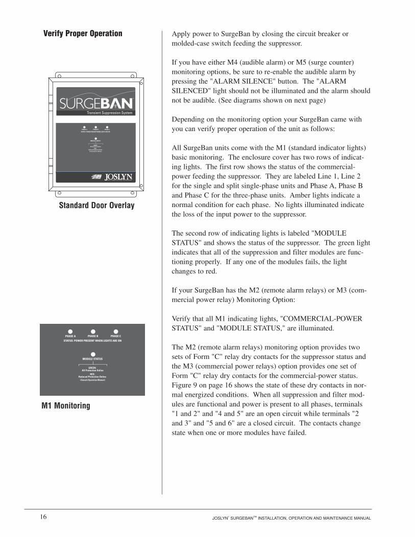
Apply power to SurgeBan by closing the circuit breaker or molded-case switch feeding the suppressor.
If you have either M4 (audible alarm) or M5 (surge counter)monitoring options, be sure to re-enable the audible alarm bypressing the "ALARM SILENCE" button. The "ALARMSILENCED" light should not be illuminated and the alarm shouldnot be audible. (See diagrams shown on next page)
Depending on the monitoring option your SurgeBan came withyou can verify proper operation of the unit as follows:
All SurgeBan units come with the M1 (standard indicator lights)basic monitoring. The enclosure cover has two rows of indicat-ing lights. The first row shows the status of the commercial-power feeding the suppressor. They are labeled Line 1, Line 2for the single and split single-phase units and Phase A, Phase Band Phase C for the three-phase units. Amber lights indicate anormal condition for each phase. No lights illuminated indicatethe loss of the input power to the suppressor.
The second row of indicating lights is labeled "MODULESTATUS" and shows the status of the suppressor. The green lightindicates that all of the suppression and filter modules are func-tioning properly. If any one of the modules fails, the lightchanges to red.
If your SurgeBan has the M2 (remote alarm relays) or M3 (com-mercial power relay) Monitoring Option:
Verify that all M1 indicating lights, "COMMERCIAL-POWERSTATUS" and "MODULE STATUS," are illuminated.
The M2 (remote alarm relays) monitoring option provides twosets of Form "C" relay dry contacts for the suppressor status andthe M3 (commercial power relays) option provides one set ofForm "C" relay dry contacts for the commercial-power status. Figure 9 on page 16 shows the state of these dry contacts in nor-mal energized conditions. When all suppression and filter mod-ules are functional and power is present to all phases, terminals"1 and 2" and "4 and 5" are an open circuit while terminals "2and 3" and "5 and 6" are a closed circuit. The contacts changestate when one or more modules have failed.
Verify Proper Operation
Standard Door Overlay
M1 Monitoring
TM

JOSLYN® SURGEBAN™ INSTALLATION, OPERATION AND MAINTENANCE MANUAL 17
Similarly, when input power is present in all phases, terminals 7and 8 are an open circuit and terminals 8 and 9 are a closed circuit. The contacts change state when the unit is encounteringloss of power to one or more phases.
Test the operation of the Form "C" contacts by de-energizingSurgeBan and checking the state of the contacts with a continuitytester or observing the effect of the contacts on the user-providedremote alarm circuits.
If your SurgeBan has the M4 (audible alarm) Monitoring Option:
Verify that all M1 power status indicating lights, COMMECIAL-POWER STATUS" and "MODULE STATUS," are illuminated.
The M4 (audible alarm) monitoring option contains an audiblealarm that should not operate under normal conditions. The audi-ble alarm can be "muted" by pressing the "ALARM SILENCE"button, which subsequently will illuminate the "ALARMSILENCED" light. Pressing the "ALARM SILENCE" buttonagain will enable the alarm.
If your SurgeBan has the M5 (surge counter) Monitoring Option:The M5 (surge counter) monitoring option is equipped with asurge event counter in addition to the L4 monitoring featuresdescribed above. The number of surges detected by the suppres-sor is displayed on an eight-digit LCD display on the front of theSurgeBan door. The counter is powered by a 10-year lithium battery, which is built into the display.
ON/OFF
M4 Monitoring, Audible Alarm Option
M5 Monitoring, Surge Counter

JOSLYN® SURGEBAN™ INSTALLATION, OPERATION AND MAINTENANCE MANUAL18
Your SurgeBan system does not require scheduled maintenance.The unit’s heavy-duty construction is designed to provide yearsof uninterrupted service.
1. A bicolor (green/red) indicating light is available on the sideof each module to help you visually identify the failed module(s). Carefully open the SurgeBan door while thepower is still applied to the suppressor and visually identifythe module(s) with a side-mounted RED indicating light.
WARNING! HAZARDOUS VOLTAGES ARE PRESENT WITHIN THESUPPRESSOR ENCLOSURE. USE EXTREME CAUTION WHEN PERFORMING THIS TASK.
2. Remove input power to SurgeBan by disconnecting theupstream overcurrent protection device. Verify that the circuits are de-energized by using a voltage tester. The indicating lights on the suppressor should not be illuminated at this time.
WARNING!
Module Replacement Procedure
Troubleshooting
INDICATION PROCEDURE
One or more commercial-power statusindicating lights are off
The upstream circuit breaker is trippedand cannot be reset
"MODULE STATUS" indicating light onSurgeBan door is illuminated RED
Verify that the input power feeding SurgeBanis energized using a voltage tester.
Contact factory for assistance.800-752-8068 or 805-968-3551, ext. 3.
One or more suppression/filter modules mayhave failed and need to be replaced. Followthe module replacement procedures below.

JOSLYN® SURGEBAN™ INSTALLATION, OPERATION AND MAINTENANCE MANUAL 19
3. Using a standard flat-head screwdriver remove the hex bolts (Part A), lock washers (Part B) and flatwashers (Part C) on the top module(s). You may need toremove the power terminal lugs (Part D) before removing thebolts holding the modules.
4. Slide the failed module(s) out.
Note: There are small interconnect pins (Part E) between modules. The pins are used to monitor the status of each module.If the pins are not properly re-installed in next step, indicatinglights on the side of the modules will not illuminate.
Module Replacement Procedure
Figure 10: Module Replacement
Part A (Hex Bolt)Part B (Lock Washer)Part C (Flat Washer)Part D (Terminal Lug)
Part E (Interconnect Pins)

JOSLYN® SURGEBAN™ INSTALLATION, OPERATION AND MAINTENANCE MANUAL20
5. Slide the replacement module(s) along with the interconnectpins back in place. Ensure that:
• the correct type of replacement module(s) is used. The color stripes on front and side labels easily identify the module. For example, all 100kA MOV modules have a red stripe on the top and side of the module.
• the identification label is facing up.
• the connection jacks are oriented directly over the interconnect pins below.
• all the interconnect pins (Part E) are installed.
6. Secure the modules with the hardware that was removed instep 2 (Part A-C) with a screwdriver or a nut driver.Reconnect the power terminal lugs (Part D) if they wereremoved previously.
7. Tighten the bolts to 20 in-lbs (2.2 Nm).
8. Close enclosure door.
9. Apply power to SurgeBan by closing the upstream overcurrent protection device. The "MODULE STATUS" light on the SurgeBan door should be illuminated GREEN. If the "MODULE STATUS" light is illuminated RED, reviewrepeat steps one through nine.
10. Carefully re-open the door while the power is applied to thesuppressor and visually verify that all of the status lights onthe side of the modules are illuminated GREEN.
WARNING! USE CAUTION! HAZARDOUS VOLTAGES AREPRESENT IN THE ENCLOSURE.
Missing status light(s) on the side of module(s) indicates that you are missing interconnect pins (Part E). If so, repeat module replacement steps again.
11. Close and secure the door.
WARNING!

JOSLYN® SURGEBAN™ INSTALLATION, OPERATION AND MAINTENANCE MANUAL 21
Our staff is ready to support you and answer any questions.
Monday through Friday, 7:00 a.m. to 5:00 p.m. (PST)800-752-8068 or 805-968-3551, ext. 3.
Joslyn SurgeBan products are warranted for a period of 10 yearsfrom date of shipment. A five-year warranty extension is available.
In the event that any module or subassembly within the suppressorfails to perform as specified during the warranty period, call ourTechnical Support at 800-752-8068 or 805-968-3551 to obtain aReturn Material Authorization number. We will immediately ship areplacement for the defective parts free of charge (installation laborand site preparations excluded).
Return the defective parts to Joslyn within 30 days of receiving thereplacement. Failure to return the defective parts will result inbilling for the replacement parts. To help expedite the return procedures, please have the following information at hand when youcontact Joslyn:
Technical Assistance
Returns and Warranty Procedures
INFORMATION EXAMPLE
Model Number
Date Code
Date of Purchase
Sales Order Number
Description of Failure
Desired Action from Joslyn
SBM200-120/240-2A6B
2100
September 2000
C019047
Cannot silence the audible alarm
Repair and return

JOSLYN® SURGEBAN™ INSTALLATION, OPERATION AND MAINTENANCE MANUAL22
The Company warrants that the purchased item (the "Product")shall meet Joslyn standards and specifications and be free fromdefects in materials and/or workmanship. Should any failure toconform to this warranty appear within ten (10) years of the dateof shipment of the Product, the Company shall either repair orreplace the defective Product, or part thereof, upon return to itsmanufacturing facility. A Return Material Authorization (RMA)number must be obtained from the Company’s Customer Servicedepartment before returning any Products.
The Company shall have no liability under this warranty forproblems or defects directly or indirectly caused by misuse of theProduct, alteration of the Product (including removal of anywarning labels), accidents, improper installation, application,operation, or improper repair of the Product.
THIS WARRANTY REPRESENTS THE ENTIRE WARRANTYOF THE COMPANY. ALL OTHER WARRANTIES EXPRESSOR IMPLIED, ORAL OR WRITTEN, INCLUDING, BUT NOTLIMITED TO, THE WARRANTIES OF MERCHANTABILITYAND FITNESS FOR A PARTICULAR PURPOSE ARE HERE-BY DISCLAIMED.
The liability of the Company, at its sole option, under this war-ranty is expressly limited to the replacement or repair of thedefective part thereof. IN NO EVENT SHALL THE COMPANYBE LIABLE OR RESPONSIBLE FOR SPECIAL, INCIDEN-TAL OR CONSEQUENTIAL DAMAGES OF ANY KIND ORCHARACTER, NOR SHALL ITS LIABILITY EVER EXCEEDTHE PURCHASE PRICE PAID FOR SUCH DEFECTIVEPRODUCT.
Claims under this warranty must be submitted to the Companywithin thirty (30) days of discovery of any suspected productdefect.
Warranty Statement

Before Applying Power
Connecting Form C Dry Contacts
Electrical Connections
Enclosure Dimensions
Installation Methods for Common Service Configurations
Single-Phase, 2-Wire
Split-Phase, 3-Wire
3-Phase, 4-Wire WYE
3-Phase, 3-Wire (2 Sides of WYE)
3-Phase, 3-Wire DELTA
3-Phase, 2-Wire (2 Sides of DELTA)
3-Phase, 3-Wire Corner-Grounded DELTA
3-Phase, 4-Wire High-Leg DELTA
Module Replacement Procedure
Monitoring Options
Plan Your Installation
Conductor Routing
Conductor Sizing
Conduit Openings
Mounting
Pre-Installation Checklist
Returns and Warranty Procedures
Technical Assistance
Troubleshooting
Verifying Proper Operation
Warranty Statement
Your Guide to Installation
JOSLYN® SURGEBAN™ INSTALLATION, OPERATION AND MAINTENANCE MANUAL 23
Index 15
14
14
12-13
6
6
7
7
8
8
9
9
10
18-20
14
10
10
10
11
11
5
21
21
18-20
16-17
22
3-4

CURRY/5M/11.00 REV. 0 J-1615Printed in U.S.A. All Rights Reserved. PN 750-0075-005
Tel: 800.752.8058805.968.3551
Fax: 877-822-8406805-968-0922805-968-8491
Learn more about Joslyn surge protectors at http://www.joslynsurge.com
Locations in Goleta, CA and Irving, TX