plc fundamentals - quia · pdf fileate1212–plc fundamentals module 2: hardware and...
TRANSCRIPT

PLC Fundamentals Module 2:
Hardware and Terminology
PREPARED BY
Academic Services Unit
August 2011
© Applied Technology High Schools, 2011
ATE1212 – PLC Fundamentals
Module 2: Hardware and Terminology 2
Module 2: Hardware and Terminology
Module Objectives Upon successful completion of this module, students should be able to:
1. Demonstrate understanding of the various PLC models and the LOGO! features.
2. Determine the required inputs and outputs for real life problems.
3. Differentiate between Analog and Digital inputs.
4. Identify the major parts of a LOGO! in the Edutrainer Compact and describe their function.
5. Demonstrate understanding of the functions and the parts of the Conveyor Belt Application.
6. Connect input and output devices and program the LOGO! to perform simple tasks.
Module Contents: Topic Page No.
2.1 Case Study 3
2.2 PLC Inputs and Outputs 4
2.3 LOGO! Hardware 8
2.4 Sensors and Actuators 11
2.5 PLC Wiring 12
2.6 Conveyor Belt Application Parts 15
2.7 Reference Table for PLC and Interface Unit 17
2.8 Lab Activity 1 18
2.9 Lab Activity 2 20
2.10 Lab Activity 3 22
2.11 Review Exercise 23
ATE1212–PLC Fundamentals
Module 2: Hardware and Terminology 3
2.1 Case Study Here is a typical situation that you might face in an industry. Our
objective is to solve this problem by writing a proper PLC program.
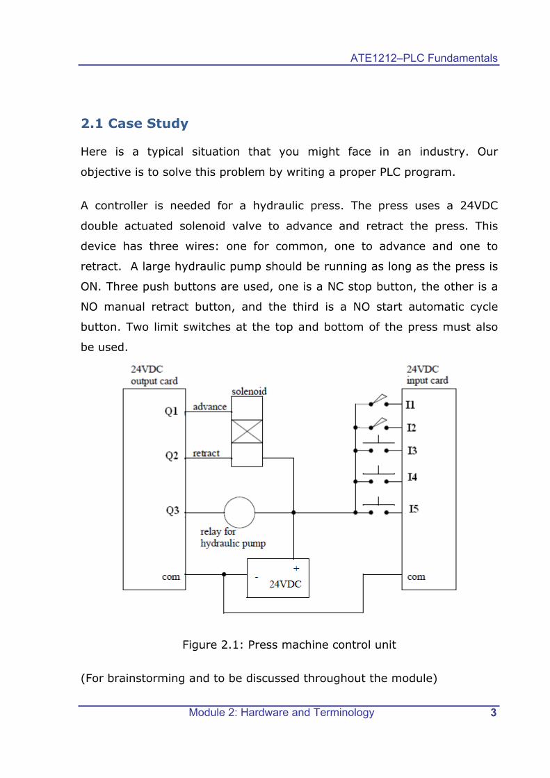
A controller is needed for a hydraulic press. The press uses a 24VDC
double actuated solenoid valve to advance and retract the press. This
device has three wires: one for common, one to advance and one to
retract. A large hydraulic pump should be running as long as the press is
ON. Three push buttons are used, one is a NC stop button, the other is a
NO manual retract button, and the third is a NO start automatic cycle
button. Two limit switches at the top and bottom of the press must also
be used.
Figure 2.1: Press machine control unit
(For brainstorming and to be discussed throughout the module)
ATE1212 – PLC Fundamentals
Module 2: Hardware and Terminology 4
2.2 PLC Inputs and Outputs
Before writing any PLC program you should be familiar with what can be
an input and what can be an output for a PLC. As you studied in the first
module, the Programmable Logic Controller is a device that can be
programmed to perform control functions. Since it is a digital device, it
stores information in the form of ON/OFF conditions referred to as binary
digits or bits. Even though the PLC uses both digital and analog signals,
the CPU can understand only digital signals.
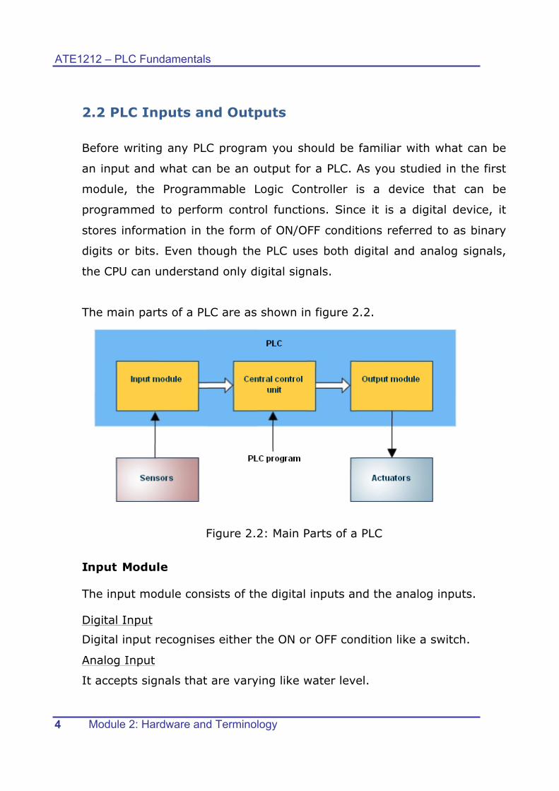
The main parts of a PLC are as shown in figure 2.2.
Figure 2.2: Main Parts of a PLC
Input Module
The input module consists of the digital inputs and the analog inputs.
Digital Input
Digital input recognises either the ON or OFF condition like a switch.
Analog Input
It accepts signals that are varying like water level.

ATE1212–PLC Fundamentals
Module 2: Hardware and Terminology 5
Observe figure 2.3. It shows the relation between the logic level and the
switch condition. Logic 1 indicates that a signal is present and the
switch is ON. Logic 0 indicates that the signal is absent or the switch
is OFF. Is the switch a digital input or an analog input? What do you
think?
Figure 2.3: Normally Open Pushbutton
A normally open (NO) pushbutton is used in the above example. When
the switch is not pressed, no voltage is present at the PLC Input 1 and
sets it to OFF state. When the switch is pressed, 24V DC is applied to the
PLC input and sets it to ON state. A normally closed (NC) pushbutton acts
opposite to the normally open (NO) pushbutton. Figure 2.4 shows the
pushbutton symbols.
Figure 2.4: Pushbutton Symbols
Figure 2.5 : Level transmitter
A level transmitter checks the
level of liquid in the tank and
provides a varying voltage to the
PLC input.
Is a level transmitter a digital or
an analog input?

ATE1212 – PLC Fundamentals
Module 2: Hardware and Terminology 6
The table below shows more examples of inputs. Classify them as digital
and analog.
Figure 2.6: Examples of Inputs
All sensors can be connected as inputs to a PLC, some examples are given
below:
• Inductive sensor
• Capacitive sensor
• Fiber optic sensor
• Temperature sensor
Class Activity Refer to the Case Study on page-4, and list all the inputs and outputs and classify them as analog and digital.
Input Output Analog/Digital

ATE1212–PLC Fundamentals
Module 2: Hardware and Terminology 7
Output Module
The output module consists of digital outputs and analog outputs.
Digital Output
Digital output can either be ON or OFF. Solenoids, contactor coils and
lamps are usually connected to digital outputs. In the example shown in
figure 2.7, the lamp can be turned ON or OFF by the PLC output.
Figure 2.7: Digital Output
Analog Output
The analog output gives a varying signal that could drive an analog
meter. Examples of analog meter outputs are speed, weight, and
temperature.
Central Control Unit The Central Control Unit contains the
Central Processor which is the brain of
the PLC. The CPU monitors the inputs
and makes decisions based on
instructions in its program memory. It
performs counting, timing, data
comparison and sequential operations.
Figure 2.8: CPU
Conduct Lab Activity 1

ATE1212 – PLC Fundamentals
Module 2: Hardware and Terminology 8
2.3 LOGO! Hardware LOGO! Is a universal logic module made by Siemens? The LOGO!
Edutrainer Compact includes the following LOGO! parts and accessories:
• LOGO! Basic Module
• LOGO! Expansion modules
• Power supply Unit
• Interface Unit
• Programming Cable
• I/O Data Cable
Figure 2.9: LOGO! Basic & Expansion Modules on Edutrainer Compact
LOGO! Basic Module
LOGO!12/24 RC is the LOGO! Controller that will be used in our
applications.
Figure 2.10: LOGO! Basic Module
ATE1212–PLC Fundamentals
Module 2: Hardware and Terminology 9
1. Inputs: The LOGO! Basic Module has 8 inputs and they are
designated as I1, I2, I3, …. I8. Inputs I1 to I6 are digital inputs, and
the inputs I7 and I8 can function as digital or analog.
2. Outputs: The LOGO! has 4 digital outputs Q1, Q2, Q3, Q4.
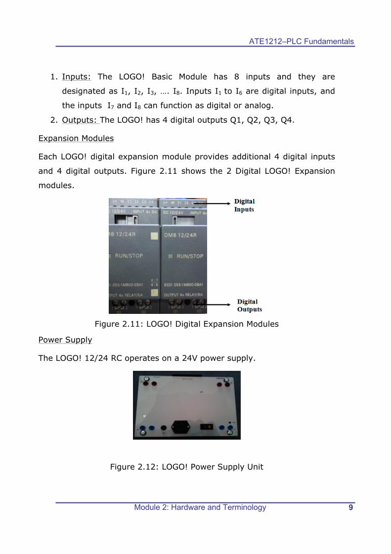
Expansion Modules
Each LOGO! digital expansion module provides additional 4 digital inputs
and 4 digital outputs. Figure 2.11 shows the 2 Digital LOGO! Expansion
modules.
Figure 2.11: LOGO! Digital Expansion Modules
Power Supply
The LOGO! 12/24 RC operates on a 24V power supply.
Figure 2.12: LOGO! Power Supply Unit
ATE1212 – PLC Fundamentals
Module 2: Hardware and Terminology 10
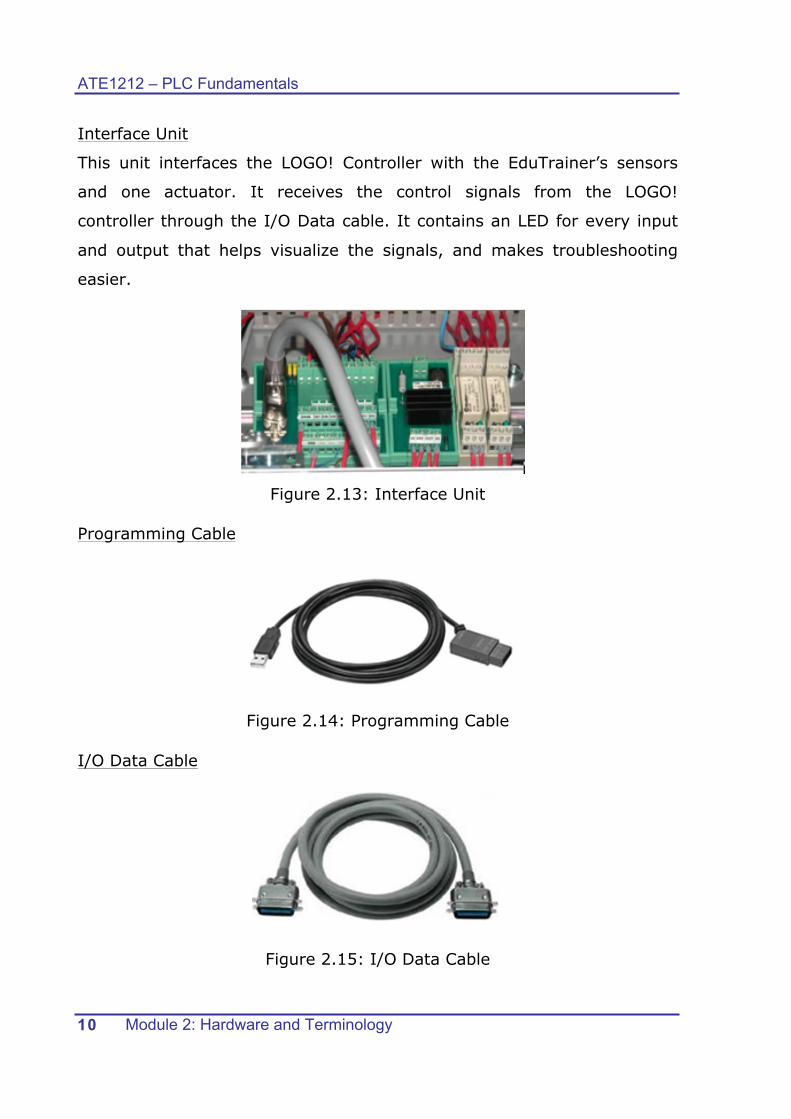
Interface Unit
This unit interfaces the LOGO! Controller with the EduTrainer’s sensors
and one actuator. It receives the control signals from the LOGO!
controller through the I/O Data cable. It contains an LED for every input
and output that helps visualize the signals, and makes troubleshooting
easier.
Figure 2.13: Interface Unit
Programming Cable
Figure 2.14: Programming Cable
I/O Data Cable
Figure 2.15: I/O Data Cable

ATE1212–PLC Fundamentals
Module 2: Hardware and Terminology 11
2.4 Sensors and Actuators A sensor is an input device that senses a physical condition and converts
it to an electrical signal. The pushbutton shown in figure 2.16 sends an
electrical signal to the PLC’s input informing the condition of the
pushbutton’s contacts.
Figure 2.16: Sensor Example
Actuators convert electrical signals from PLC outputs into physical
conditions. A motor starter (in fig 2.17) is an example of an actuator. It
will either start or stop the motor depending on the state of the PLC
output.
Figure 2.17: Actuator Example

ATE1212 – PLC Fundamentals
Module 2: Hardware and Terminology 12
2.5 PLC Wiring
Connecting the power supply
PLC devices need an electrical power supply that can be either an AC, or
DC supply. LOGO! 12/24RC needs a DC supply. Fig. 2.18 shows the
method of wiring the DC power supply to the LOGO! Module.
Figure 2.18: Connecting LOGO! to power supply
Connecting LOGO! Inputs
Figure 2.19 shows the hardware/wiring details of connecting the inputs to
the LOGO! Switch S1 is connected to I1 and switch S2 is connected to I2.
Figure 2.19: Connecting inputs
ATE1212–PLC Fundamentals
Module 2: Hardware and Terminology 13
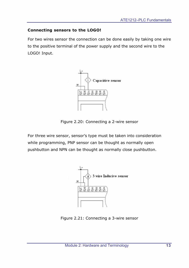
Connecting sensors to the LOGO!
For two wires sensor the connection can be done easily by taking one wire
to the positive terminal of the power supply and the second wire to the
LOGO! Input.
Figure 2.20: Connecting a 2-wire sensor
For three wire sensor, sensor’s type must be taken into consideration
while programming, PNP sensor can be thought as normally open
pushbutton and NPN can be thought as normally close pushbutton.
Figure 2.21: Connecting a 3-wire sensor

ATE1212 – PLC Fundamentals
Module 2: Hardware and Terminology 14
Connecting LOGO! Outputs
LOGO! …R… version is equipped with relay outputs. The potential of the
relay contacts is isolated from the power supply and the inputs. As shown
in fig 2.22, various loads can be connected to the relay outputs, for
example, lamps, motors, relays etc.
Figure 2.22: Connecting loads to outputs

ATE1212–PLC Fundamentals
Module 2: Hardware and Terminology 15
2.6 Conveyor Belt Application Parts
The parts of the Conveyor Belt application are indicated below along with
their functions.
1. Optoelectronic sensors:
Fiber optic barrier
This sensor is used to
detect the presence of a
work piece regardless of its
color and material.
2. Inductive Sensor
This sensor is used to
detect metal parts, and its
detection distance is up to
4 mm.
3. Conveyor Belt
This is the transportation
media on which the work
pieces are transported.
Figure 2.23: Conveyor belt parts
4. DC Motor
It moves the conveyor belt
with the aid of the gearbox.
5. Gear Box
It is used to decrease the
speed and to increase the
torque.
Figure 2.24: DC motor and gear box

ATE1212 – PLC Fundamentals
Module 2: Hardware and Terminology 16
6. Branching Module
This is a motorized assembly by which branching of the work pieces
are done.
Figure 2.25: Branching arm 7. Fiber optic barrier
This sensor is used to detect the passing of a work piece regardless of
its color and material.
8. Slide
This is the place to hold the branched work pieces.
ATE1212–PLC Fundamentals
Module 2: Hardware and Terminology 17
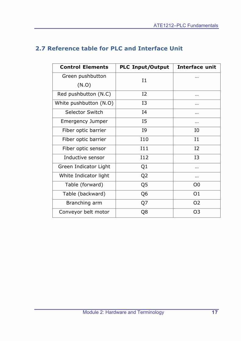
2.7 Reference table for PLC and Interface Unit
Control Elements PLC Input/Output Interface unit
Green pushbutton
(N.O) I1
…
Red pushbutton (N.C) I2 …
White pushbutton (N.O) I3 …
Selector Switch I4 …
Emergency Jumper I5 …
Fiber optic barrier I9 I0
Fiber optic barrier I10 I1
Fiber optic sensor I11 I2
Inductive sensor I12 I3
Green Indicator Light Q1 …
White Indicator light Q2 …
Table (forward) Q5 O0
Table (backward) Q6 O1
Branching arm Q7 O2
Conveyor belt motor Q8 O3

ATE1212 – PLC Fundamentals
Module 2: Hardware and Terminology 18
2.8 Lab Activity 1 Objective: To identify the Normally Open and Normally Closed
pushbuttons on the LOGO! BASIC Control unit.
Figure 2.26: LOGO! Control Unit
The LOGO! Control Unit has three pushbuttons as shown in fig 2.26.
Perform this activity to identify the NO and NC pushbuttons.
Procedure:
A. Enter a program to turn on the white indicator light (Q3) when the
green pushbutton (I1) is pressed. Run the program and observe the
result. Has the white light turned ON?
________________________________________________ If yes, the green pushbutton is a NO pushbutton.
B. Enter a program to turn on the white indicator light (Q3) when the
red pushbutton (I2) is pressed. Run the program and observe the
result. Has the white light turned ON?
________________________________________________ If not, the red pushbutton is a NC pushbutton. It becomes open
when pressed.
ATE1212–PLC Fundamentals
Module 2: Hardware and Terminology 19
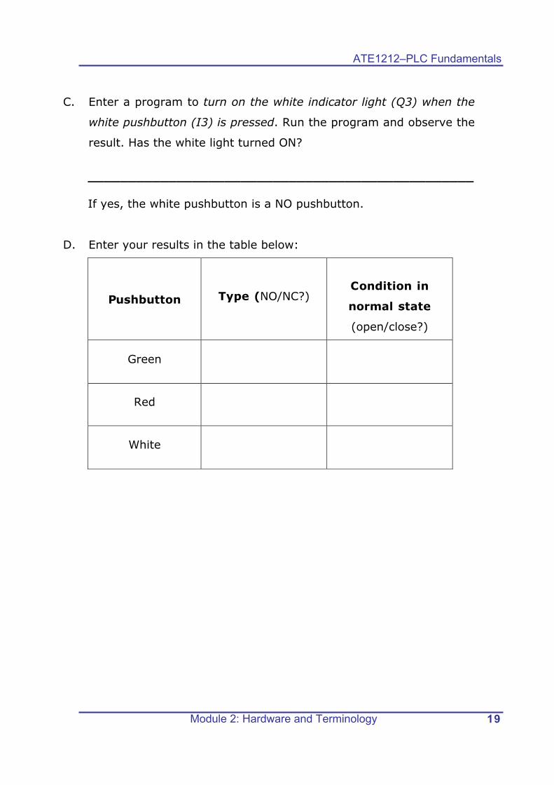
C. Enter a program to turn on the white indicator light (Q3) when the
white pushbutton (I3) is pressed. Run the program and observe the
result. Has the white light turned ON?
________________________________________________ If yes, the white pushbutton is a NO pushbutton.
D. Enter your results in the table below:
Pushbutton
Type (NO/NC?)
Condition in
normal state
(open/close?)
Green
Red
White
ATE1212 – PLC Fundamentals
Module 2: Hardware and Terminology 20
2.9 Lab Activity 2 Objective: To familiarize with the LOGO! Interface Unit and the expansion modules. Procedure:
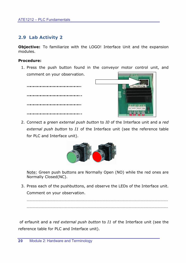
1. Press the push button found in the conveyor motor control unit, and
comment on your observation.
………………………………………… ………………………………………... ………………………………………… ………………………………………...
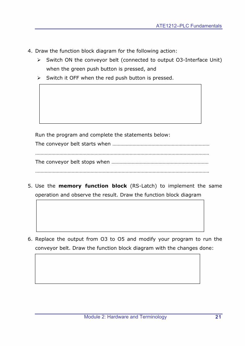
2. Connect a green external push button to I0 of the Interface unit and a red
external push button to I1 of the Interface unit (see the reference table
for PLC and Interface unit).
Note: Green push buttons are Normally Open (NO) while the red ones are Normally Closed(NC).
3. Press each of the pushbuttons, and observe the LEDs of the Interface unit.
Comment on your observation.
…………………………………………………………………………………………………………………………
…………………………………………………………………………………………………………………………
of erfaunit and a red external push button to I1 of the Interface unit (see the
reference table for PLC and Interface unit).
ATE1212–PLC Fundamentals
Module 2: Hardware and Terminology 21
4. Draw the function block diagram for the following action:
Switch ON the conveyor belt (connected to output O3-Interface Unit)
when the green push button is pressed, and
Switch it OFF when the red push button is pressed.
Run the program and complete the statements below:
The conveyor belt starts when ………………………………………………………………
…………………………………………………………………………………………………………………
The conveyor belt stops when ………………………………………………………………
…………………………………………………………………………………………………………………
5. Use the memory function block (RS-Latch) to implement the same
operation and observe the result. Draw the function block diagram
6. Replace the output from O3 to O5 and modify your program to run the
conveyor belt. Draw the function block diagram with the changes done:

ATE1212 – PLC Fundamentals
Module 2: Hardware and Terminology 22
2.10 Lab Activity 3 Objective: To test the function of the optical sensor and inductive sensor connected to the Interface Unit. Procedure:
1. Connect the optical sensor shown to Input I3 of Interface unit.
2. Notice the status of LEDs of the Interfacing unit when there is no object in front of the sensor; write your observation below:
……………………………………………………………………………………………………………………
……………………………………………………………………………………………………
3. Move your hand forward and backward in front of the same sensor and observe the status of LEDs of the Interfacing unit. Comment on your observation.
……………………………………………………………………………………………………………………
……………………………………………………………………………………………………
4. Create a program that turns ON the conveyor belt when the selector switch is switched ON, the branching arm should move when the inductive sensor detects a metallic piece.

ATE1212–PLC Fundamentals
Module 2: Hardware and Terminology 23
2.11 Review Exercise
1. Read the case study at the beginning of this module, and then draw
all the inputs and outputs and connect them to the LOGO! PLC given
below.

ATE1212 – PLC Fundamentals
Module 2: Hardware and Terminology 24
2. Write T for the correct statement and F for the wrong statement.
No Statement T/F
a
The control panel of LOGO PLC consists of 4 pushbuttons, 1 Selector switch, and 2 Lamps.
b
The output voltage of the Power Supply Unit is 24VDC.
c
The inductive sensor is used to detect metals only.
d
I1 is the first output for LOGO! PLC and Q1 is the first input.
3. Give three examples for each one of the following :
Digital Input
Analog Input
Digital Output
Analog Output

ATE1212–PLC Fundamentals
Module 2: Hardware and Terminology 25
4. A normally open pushbutton is used to turn ON an automatic filling
system. When the normally closed liquid level detector is activated,
a pump starts filling the tank. Once the tank is full a normally open
liquid level detector sends a signal to the PLC and the PLC turns the
pump OFF.
Complete the wiring diagram below.