ate321 plc module1 - quia module 1: introduction to plc ... • they can communicate with other...
TRANSCRIPT

PLC
Module 1: Introduction to PLC
PREPARED BY
IAT Curriculum Unit
Jan 2010
© Institute of Applied Technology, 2010

ATE321 – PLC
Module 1: Introduction to PLC 2
Module 1: Introduction to PLC
Module Objectives Upon successful completion of this module, students will be:
1. able to demonstrate knowledge of control systems.
2. familiar with the concept of manual and automatic control.
3. familiar with the basics of PLC, its function, advantages, applications and the manufacturers.
4. identify the main parts of the Siemens LOGO! PLC Module.
5. capable of programming the Siemens LOGO! PLC Module through its Basic Control Unit using simple commands.
6. Use simple LOGO! commands to control the Edutrainer control elements.
Module Contents: Topic Page No.
1.1 Introduction 3
1.2 Programmable Logic Controller 5
1.3 Lab Activity 1 8
1.4 Lab Activity 2 11
1.5 Lab Activity 3 13
1.6 Module Exercise 17
1.7 Assignment 19

ATE321–PLC
Module 1: Introduction to PLC 3
1.1 Introduction
In everyday operations or industrial processes, we come across situations
where there is a need to control some device or a physical quantity such
as time, temperature, sound, light and so on, to get the required result or
output.
For example, do you think an airplane would be useful to a pilot, if he
cannot make it go where he wants it to go? Or would an air-conditioner
be useful, if the temperature in a room cannot be controlled? In both the
examples, there is a need to control a process.
Control is a broad term that means anything from a toggle switch to a
complex system of components. Control can either be manual or
automatic.
Fig 1.1: Examples of Control
Manual Control
Control is said to be done manually
when a user performs an action for
the system to function. For
example, the user might flip the
switch of a manual starter to start
and stop a motor (fig 1.2)
Fig 1.2: Example of Manual Control

ATE321 – PLC
Module 1: Introduction to PLC 4
Automatic Contol
Control is said to be automatic
when the action is performed
automatically in response to set
conditions.
Fig 1.3: Example of Automatic Control
Machines can be controlled manually or automatically. Usually, there is a
combination of manual and automatic control. For example, a process
that is started manually may stop automatically when certain conditions
are met.
Fig 1.4: Manual & Automatic Control Example
From the examples, it is clear that a Control System is a system that
can sense, switch and/or control an operation. It operates on an input
signal and controls the process in order to provide an output signal. This
is shown in the block diagram in fig 1.5:
Fig 1.5: Elements of a Control System
Input Process Output

ATE321–PLC
Module 1: Introduction to PLC 5
1.2 Programmable Logic Controller (PLC)
A Programmable Logic Controller (or PLC) is a specialised digital controller
that can control machines and processes. They monitor inputs, make
decisions, and control outputs in order to automate machines and
processes. Fig 1.6 demonstrates its function.
Fig 1.6: PLC Function demonstration
PLCs have been used for industrial and
commercial applications. Almost any production
or assembly line, machine function or process
can be controlled by a PLC.
Fig 1.7: PLC
PLC Advantages
• They are highly reliable, fast and flexible.
• They can handle severe conditions such as dust, humidity etc.
• They are less expensive.
• They can communicate with other controllers.
• They are easy to program and troubleshoot.
ATE321 – PLC
Module 1: Introduction to PLC 6
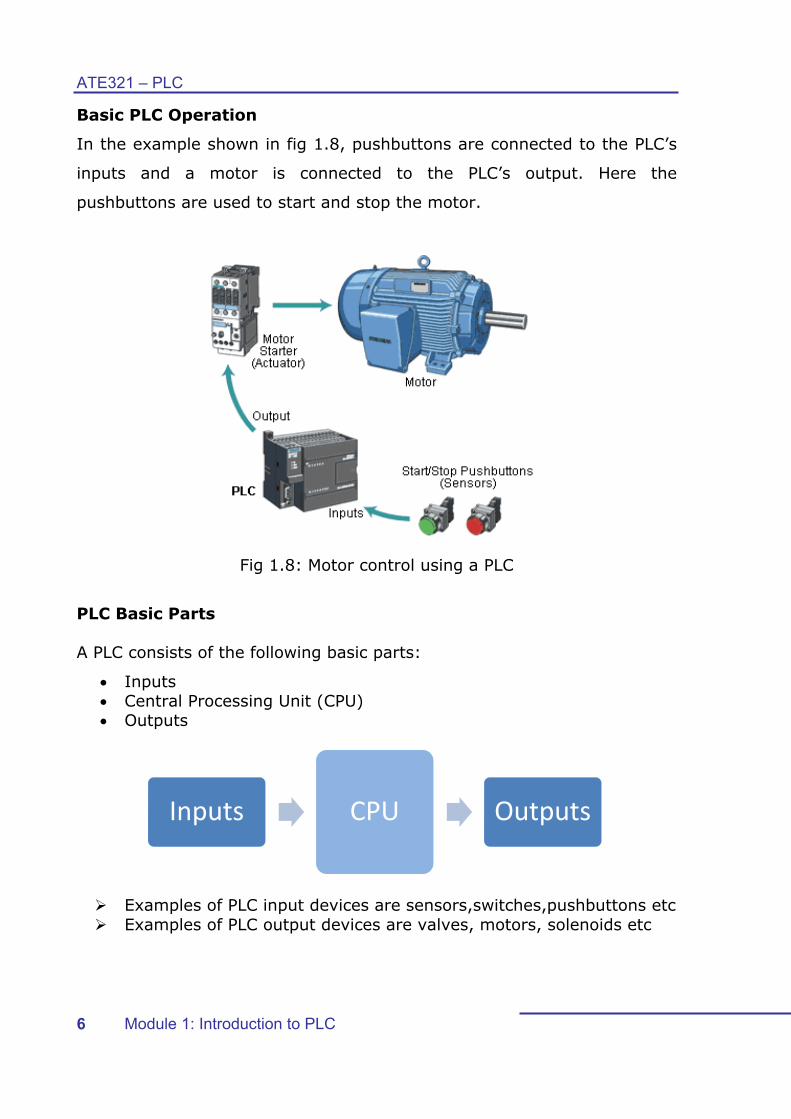
Basic PLC Operation
In the example shown in fig 1.8, pushbuttons are connected to the PLC’s
inputs and a motor is connected to the PLC’s output. Here the
pushbuttons are used to start and stop the motor.
Fig 1.8: Motor control using a PLC
PLC Basic Parts A PLC consists of the following basic parts:
• Inputs • Central Processing Unit (CPU) • Outputs
Examples of PLC input devices are sensors,switches,pushbuttons etc Examples of PLC output devices are valves, motors, solenoids etc
Inputs CPU Outputs

PLC
A Psho
PLC
The
Sie
C Applica
PLC can bwn below
Au
C Manufa
e PLC tha
mens.Th
ations
be used iw:
tomatic D
acturers
at will be
he table b
in a wide
Producti
Doors
e introduc
below sho
M
e range o
on and a
ced in th
ws a list
Module 1:
of applica
ssembly
is course
of other P
Introductio
ations, so
lines
Traffic
e is the L
PLC Manu
ATE
on to PLC
ome of w
Lights
LOGO! P
ufacturers
E321–PLC
7
which are
PLC from
s.

ATE321 – PLC
Module 1: Introduction to PLC 8
1.3 Lab Activity 1 Objective: To familiarise with the Siemens LOGO! PLC Module. Procedure: The following are the 12 main components of the LOGO!
Basic PLC module:
• One LOGO! Basic which operates on 24V dc supply and has: 6 digital inputs 2 analog inputs 4 digital outputs
• Display unit • Control Unit for LOGO! Programming • PC Interface • Two expansion modules that have:
4 digital inputs 4 digital outputs
• Status display LEDs that indicate RUN/STOP status • Submin D Socket • 24VDC safety socket • 0V safety socket • Control elements • Emergency-stop bridge • SysLink Interface
1. Identify the LOGO! Basic PLC module components on the
EduTrainer that are marked in the figure and write them in the table provided:

ATE321–PLC
Module 1: Introduction to PLC 9
Number Component/Part
1
2
3
4
5
6
7
8
9
10
11
12
Table 1.1
Review the parts and mark them in the picture below:

ATE321 – PLC
Module 1: Introduction to PLC 10
2. Identify the three parts on the LOGO! Basic control unit and name them:
1. __________________________________________________
2. __________________________________________________
3. __________________________________________________
What is the function of this unit? _____________________________________________________ ________________________________________________
3. Measure the output voltage of the power supply unit with the help of a multimeter as shown in figure below:
Record the dc output voltage. ____________________________________________________

ATE321–PLC
Module 1: Introduction to PLC 11
1.4 Lab Activity 2 Objective: To familiarise with the LOGO! Basic Control unit using simple commands. Procedure:
1. Set the day, time and date Follow the steps below to set the day, time and date.
Switch on the power supply. Press the ESC key on the LOGO! Basic module Select Set Select Clock Press the and to change the day and press OK to
confirm. Move to date by using the side arrows. Follow the same procedure to set the date and year and press
OK to confirm. Press ESC to return to the main screen.
2. Enter your first program on LOGO! using the on-board keys. The digital inputs are denoted by the letter I such as I1, I2 and so
on, and the digital outputs are denoted as Q1, Q2 and so on. Program the PLC to turn on Q1 when I3 is ON.
Press ESC to come to the main screen and follow the steps below: Step 1 Step 2
Clear prg clears previous program
Step 3
Press Yes and press OK.
Step 4
Step 5
Step 6
Step 7
Select Q1 as output
Step 8
Select I3 as input by using the OK button.

ATE321 – PLC
Module 1: Introduction to PLC 12
Observation:
1. Press ESC to return to the main screen and press start to run the program.
Press the white pushbutton (I3) and observe the result. Can you
identify the Q1 output? What do you observe? __________________________________________________ __________________________________________________
2. Stop and clear the program. Repeat the steps by changing the input to I1. What do you observe?
________________________________________________________ ________________________________________________________
3. Based on your experiment, identify which control element is connected to the following PLC inputs and outputs:
PLC input Control Element
I3
I1
PLC Output Control Element
Q1
Table 1.2
ATE321–PLC
Module 1: Introduction to PLC 13
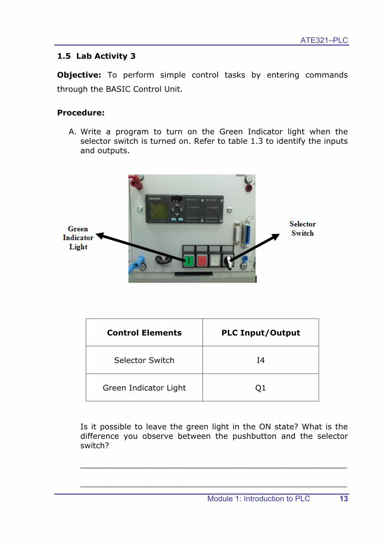
1.5 Lab Activity 3 Objective: To perform simple control tasks by entering commands
through the BASIC Control Unit.
Procedure:
A. Write a program to turn on the Green Indicator light when the selector switch is turned on. Refer to table 1.3 to identify the inputs and outputs.
Control Elements PLC Input/Output
Selector Switch I4
Green Indicator Light Q1
Is it possible to leave the green light in the ON state? What is the difference you observe between the pushbutton and the selector switch?
______________________________________________________
______________________________________________________

ATE321 – PLC
Module 1: Introduction to PLC 14
B. Write a program to move the table forward when the white pushbutton is pressed.
Control Elements PLC Input/Output
Table (forward) Q5
Table (backward) Q6
White pushbutton I3
What changes should you make in the program to move the table backward when the white pushbutton is pressed?
______________________________________________________
______________________________________________________

ATE321–PLC
Module 1: Introduction to PLC 15
C. Write a program to start the conveyor belt motor when the green pushbutton is pressed.
Control Elements PLC Input/Output
Conveyor belt motor Q8
Green pushbutton I1
Branching arm Q7
What changes should you make in the program to move the branching arm when the green pushbutton is pressed?
______________________________________________________
______________________________________________________

ATE321 – PLC
Module 1: Introduction to PLC 16
D. Write a program to turn on the White indicator light when the
inductive sensor senses a metal piece.
Control Elements PLC Input/Output
White Indicator light Q2
Inductive sensor I12
What changes should you make in the program to move the branching arm when this sensor senses a metal piece?
______________________________________________________
______________________________________________________
White Indicator Light

ATE321–PLC
Module 1: Introduction to PLC 17
1.6 Module Exercise 1. What are the elements of a control system? Include the elements to
complete the block diagram given below:
2. PLC stands for ___________________ ___________
____________
3. What is a PLC?
______________________________________________________ ______________________________________________________ ______________________________________________________
4. Based on your knowledge of microcontrollers, what do you think is
the difference between a PLC and a microcontroller? Complete the T-
chart below to show the difference:
PLC Microcontroller

ATE321 – PLC
Module 1: Introduction to PLC 18
5. Mark the parts that are indicated in the table below:
Number Component/Part
1
3
4
8
11
12
6. List three advantages of using a PLC:
______________________________________________________ ______________________________________________________ ______________________________________________________
ATE321–PLC
Module 1: Introduction to PLC 19
1.7 Assignment Complete any one of the tasks using any one of the suitable Microsoft Office tools. Task-1: Use the internet to identify one commercial application and two industrial applications of a PLC other than the ones listed in the module, and prepare a powerpoint presentation or a poster that lists those PLC applications. The powerpoint slides (or the poster) must include the following contents:
Assignment Title: PLC Applications
Title of application-1, picture and brief description.
Title of application-2, picture and brief description.
Title of application-3, picture and brief description. Task-2: Prepare a powerpoint presentation or a chart that includes the following:
• A picture of the Logo! Basic Control unit with all its parts marked neatly.
• A list of all the LOGO! Edutrainer control elements that you have used in your lab activities in this module. Include the following details:
Control Element Input or Output? PLC Input/Output