plastics mold engineering handbook 1
TRANSCRIPT

x PREFACE TO THIRD EDITION
data, and reminders to keep them aware of some critical items at just the right time to prevent error. Thus, an extensive checklist is presented. It will insure consideration of the potential hazards, weaknesses, and misunder- standings that face mold designers, engineers, and builders.
There are, of course, many variations of molds, whatever their general classifications. Naturally, it is not possible in a presentation on mold fun- damentals to describe in detail the very complex designs that sometimes evolve. However, you can be sure that any complex design can be broken down into its simplistic fundamentals as outlined in this text.
We have tried to mention all mold-design and moldmaking methods- even those that are rarely used. Our purpose here is to stimulate interest and
Contents
to encourage original study. We wish to thank the many users of the previous editions for their helpful
suggestions for changes and improvements in the text. Since many pieces of equipment that are obsolete by present standards continue to be used, we have described mold types for some of them. For instance, this text is used in parts of the world where very primitive equipment is employed. There, the people need data on molds for simple processing equipment, and to use the supply of moldmaking materials, which may be available in these lo- 2 calities but far removed from suppliers of standard mold parts. 15
We are indeed grateful for the widespread acceptance and distribution of . . 18 this text since it was first published in 1946 by the American Technical Society. We appreciate the obligation this places on us to be accurate, pre- cise, and factual. In preparing this new edition, we have carefully re- searched the intervening developments and have made every effort to pro- ,
vide serious readers with a body of knowledge that they can carry confidently I
J. HARRY DUBOIS h % W k A ~ i f q-: 1 id Morris Plains, New Jersey %
I + i 37 WAYNE I. PRIBBLE
:, 2 )CLm713a @7 New Haven, Indiana && 1 , . .Xi1
,; t,.w • PR~ESSES, EQUIPMENT AND Pawl E. Ferland
64 65 82 86
vii
ix

S
SLrface Finish, Molds and Parts
CONTENTS xi11 I$', f . ..'r:,,,, %rink Fit Allowances
Mold ?%ts W e ~ M d d Parts T e m m r e Control Media and Methods Wbtt$@ Cavities and Plungers ; 1 D p W Cavities and Balanced Molds
Burfab@ Phishes and Textured Molds Refe
iCX)MPRESSION MOLDS, Wayne I. Pribble
Bgign of 12-Cavity Semiautomatic Mold i#@ng-Box Molds W i n g Shoe and Stripper Plate Molds M t i v e Mol& &&$positive Molds kbmtvity Gang Molds
Bracket Mold
pression Mold Considerations
INJECTION MOLDS FOR S, S. E. Tinkham and Wayne I. Pribble 299
300

v r - 7 -
- d z ( q j ' l ~ \ , ' v ' 3 ~ : : - 7 . . , . , , t \ ,,,< i.!{-b:d&iI{-I ,!? .I c 9; QtXD Mom DBSIGN, Leon R* Egg ,a!~r:aM -9-
1: $2 ,*it.nrl'i: TO^ &' '
, 'j'

Chapter Introduction to 1 Plastics Processing I
I Revised by Wayne I . Pribble
Wqty of applications in d i v a rnmufacturing fields (Fig. 1 .1 ) . These ma-
quality of the tool-make& wark. The molds and dies used are the
of dies or moklo bwe used ile it "sets" or hardens to
. - -J

2 PLASTICS MOLD ENGlNEERlNO HANPBOOK


8 PLASTICS MOLD ENOlNEERlNO HANDBOOK
Continuous Extrusion
Plastics materials are extruded in continuous strips of regular section, Fig. I' rl 1 1.7. This is done by a machine which operates much like a sausage stuffer. The raw material is placed in a hopper, where it is moved into and through a heating chamber by a screw feed. At the die end of the heating cylinder the material (which has been heated and compressed to a plastie mass) is forced through a die which shapes the extruded section. A moving belt carries the section away from the die, and the final dimension of the part is governed L by the speed of this take-off belt. The extruded piece is stretched to a reduced sec-tion area by the take-off belt.
The extrusion dies are relatively simple and inexpensive and are quite similar to extrusion dies used for the low-melting-point metals. Figure 1.8 shows the rear or screw side of an extrusion die used to make a rectangular strip. Note the tapered entry. k" ddh
Blow olding
Botties and other hollow articles are extrusion blow molded of thermoplas- tic materials. For this, a tube, called a parison, may be extruded and this hot thermoplastic tube is clamped between the fttces of a blow mold. Air pres- 1 ' sure is imwdktf~ly applied in the clamped tube to expand it and fill out the I mold ntour ( ~ i g . 119).
An extrusion die E&3
INTRODUCTION TO PLASTICS PROCESSING 9
Plasti~izi reciprae: screw
Basic extrusion blowhgpdnoiple for blow molding. The parison is a tube of molten i& i s clamped bet-n the die bEves and expanded to tlie die shape by air pressure. C
te process, cdkd -&law molding forms the parison in n and then 1nr4-m~ quiokly into the blow mold position for ternal air pressure w &@wn by Fig. 1 .la. In the final position,
O E ~ is stripped from the.~ote p;fn while the msld is open.
lding machines are cqdppwl to rotate the molds continuously in the horizontal axis during the molding cycle. This pro- --
dwre facilitates the p r d e o n of i n r q d hoflow parts of almost ,aqp-open or closed-rigid or flexible. Ip process, a mea- d liquid or powdered *w &@dd is p l w d in each mold
@ @ mold halves closed, they art3 -ale . i-n 3 heated area while
~psly in the - . t w ~ ' ~ h n e s - until the mtirqiassr mdd surface and :nin -
thesmophstics has formed in the mold su&a&, the, t J@@ 'a mter spray or air blast while rotation continued ha- IF&$ 1.41 a n faIzn:ated by aluminum casting, rnacM-* A* **-ST - - . %rbp.E~mmd mbkel. The molds are vented byb%
QLW& &I@. Wzcils on the &tpk mold designs bm ,%& mmd&nnc ma GP-


14 PLASTICS MOLD ENGINEERING H A N ~ ~ ~ INTRODUCTION TO PLASTICS PROCESSiNG 15
old then opens slowly under proper controls to per- n. In the low pressure process, conventional injec-
with resins containing preblended foaming agents or ded by.a "piped in" gas.
the mold-maker. Good tools
, . . ,-. ..{' I


18 PLASTICS MOLD .EMGINEERIKT MAWDBQW
The metal vqs&a$3~wsO;ies mak6ptmy jbs, and fixtures out of plas- tics, and thew m&- are identifed by thc snmsp*urira rooling. The plas- tics pr ies refer to their tcl& as molds, dies, and fixtures.
REFEREM- Basic Mold Types Baq, ~ f i c , ~ @ m & n g Design fir Flasrtcs, Mew YD&. Van Nostrand Reinhold, ~ ~ c k , Ronald D., P M i c s Prodird Deaig~n, 2nd &., New Van Nostrand Reinhold, and Features
1980. &mhdt, E. C, f i ~ s s i n g of T h e m p k W c Ma%*, New York: Van N0s-d Reinhold,
1974. ' Revised by Wayne I. Pribble
. A mold is only one item in a series of , E@&W td., ~ k w Pb& M-F*rM+ !W. material. The vast majority of molds are ~ f * m d Ph9da, pew York: Yap Mwtrend Reinhold, which open and close. One half of the
s 0 . 1 w t @ ~ - ~ Mign), in Mod- Yerk; !JWbw-Hill, 1984.
half forms the inside of a part, 1984. contour of a part.
For further reading, we suggest: wu, a w e R., to lasers for practical way to do the tough fab&atiagjobs~ Mod- cialize in resins, fillers,
em Pfastics Magaz im, p. 61, May 1984. ther components that terial. The final mate-
, , r from many different

BASIC MOLD T m S AND FEATURES 21
extremely stmple molds of wood and m t e r are usually by the hobbyist who wants to experiment with pbtks . Some readers will qua- tion this aaehof i M u s e break-away pbSt€% b Very COmmon in &&? -0xY and fi&+s lg@p and in the molding Of a* d m and intriwlte'shap for the a h d t idustry.
Pla3tjcs old Engineering will not ableto cover eventhin&. This ere- lude to basic &$M tgrpes and feartum,&jB &&90~ Bn idtial undwBnding of the molds only. We urge you to co~lect 3tZdog and house orws which describe and promote n w meth& Qf-Ow Fh6h@tiom of old methods that have put togetlfer to make a fahat ing device that probably g l l do a job previou~ly considered impossible. Our point here is-ne most compliqted mold ever built Was made UP of the simple cmponentg and $.Ct'& 'described in this text. bfosI inventions are simply
6. Vacuum formi

I - -
BASIC MOLD TYPES AND FEATURES 23
1 SPRUE BUSHING 2 LOCATING RING 3 TOP CLAMPING
PLATE 4 FRONT CAVITY PLATE 5 R M R CAVITY PLATE 6 SOPPORT PLATE 7 EJECTOR HOUSING 8 EJECTOR RETAINER
PLATE 9 EJECTOR PLATE
l Q WECToR PINS TI CORE INSERT (male
section) la CAVITY I N E R T (ternale
section) 1 SPRUE WLLER PIN 14 WATER LINES
I 1.
pro. 2.2. Various cornpo&p&&~d~1e twgplate iqjection mold used for injection mold- ing. (Courtesy Dow Chernic@&C~;, 4f&#EBnd, MI)
Ci - i ,.. molds and operating t this type. Since hy- draulic presses are mo hcr ip t ion is given of the operation of a mo press, Two general types of presses are u aed the t ~ w m t r o k e press. The downstroke press &, ~ 1 i r d e ~ 90 that the ram and top platen are m p m u r e to the mold. This t p e of press is wide such parts as truck vantage of this press
- and allows the operat 10 foot square are not uncommon b r g e Molds in Cha
the main ram to its fully open position) or double-acting (on& . uses pressure in one direction to Uclose" and pressure in the othab
compression molding, another cylinder is frequently used to operate
-.-,r - . v - - - 7 - z - 7
A . A ~ h

on the press platens with clamp bolts at
t-hand press ,in Fig. 2.3 is a double ejector
features shown are:
2 . air cylinder (2-way); 3. U-washer;


of two h t inc t types- A plunger or auxiliary ram trans- S the 6'F most often used. It has a built-in transfer pot
GENERAL MOLD TYPES
The variety of molding materials and molding methods has necessitated the development of many mold types in order that full advantage of the material possibilities might be secured. Three general types of molds are used and these may be subdivided into several classes. The three general types are compression molds, transfer molds and injection molds.
These three systems, described in Chapter 1, will be reviewed here. There is no particular significance to the order in which they are presented. His- torically, compression molds were the very first types to be used in the middle 1800s. The injection molds came into being in the 19% for the thermoplastics processing and the transfer molds came i n t ~ use in the 1930s. For a history of the development of the industry, ref^^^ should be made to Plastics History, U.S.A.*
Compression Molds


BASIC MOLr 'YPES AND FEATURES 33
ession molded parts. In most cases which involve molding proble h as those itemized above, the lower final cost of the part, after all
; A variation of the full size transfer mold is the hand-transfer illustra ,in Fig. 2.8. These molds usually have a loose plate and are relatively s in size. They are used where inserts must be held at one or both ends
Inption Molds
material in it). After the application of pressure to close the mold and . ,
it tightly clamped against injection pressure; the molten plastics mate- , ' is forced into the closed cavity by a source of pressure other than that 1
caused the mold to close. The melting of the plastics material in the I
ve machine cylinder is calledplasticizing. Figure 2.9 shows a molded -
rt as it comes from the injection mold. The runner clearly shows as the ss-bar in front of the operators left arm. One gate is indicated by his left mb. The molten material passes through the runner and gates (2) on its y into the cavity. The point at which the molten plastics material passes m the runner into the cavity is called the gate. You will note that we refer @wine classifiwtion of materials. T 'flowing into the cavity." This'bavity means the space between the male and manufacturing technique b o ~
n and the female section into which the molten plastics will eventually r of tk raw material tha into the desired shape and detail. The point at which the core and
vity separate or move apart when the mold is opened is called the parting e. Chapters 7 and 8 detail the different manners in which the material can introduced into the cavity through a gate or gates in various locations.
ch location has its advantage and disadvantages. The proper choice of ting is one of the essential fundamentals of mold engineering thatmust mastered by the mold designer. Injection molds are used for molding either thermosetting or thermoplastic

34 PLASTICS MOLD ENGINEERING HANDBOOK
usually split lengthwise, and the inflated object retains the size and shape of the inside of the mold. The blow mold is a variation of the split-wedge or split-cavity mold. The major difference is that in this case the entire mold '
is split, and temperature control is provided within each half of the mold. The clamping of the split halves is accomplished by action of the blow molding machine. The design and construction are quite different from those of conventional molds. This subject is covered in Chapter 11 as a separate and special problem.
The expanded-plastics, reaction injection and foam molds are treated separately in Chapter 13. Structural foam is an element of the expanded plastics and requires unique mold designs, as well as specially adapted injection machines. Here, again, the serious designer must pay close atten-
. , tion to the trade literature available for the many speciiic materials that can be foam molded. Essentially, the molds used for foam molding confine the charge while it is expanded by heat, or gas pressure liberated in the heating .process, filling the space between the cavity and core to form the desired .molded part.
SPECIFIC TYPES OF MOLDS
The second manner in which molds are described is by the manner in which they are to be operated. Molds can be classXH as a hand molds, sedauto- matic molds or automatic molds. lifts for opening a hi.., .nold.


, f1' . mi. %FR This
and keep it closed during the curing or lret t m&tlon .or harelrshg time . r&&MECl fovr harden sufficiently to be ejected from the mo
in other publications the- pke-nomaan of p
BASIC MOLD TYPES AND FEATURES 39
PLUNGER (OR FORCE) OR CORE
m-!\F@i. 2.14. Cross section. of a simple flash mold.
'b
m l o w c e other than that which closes the mold and keeps
I r armprbssion molding is designed in a manner that @ t t w . w p e asi-ly as the pressure is applied. A cross wd h bholdlu in Fig. 2.14. The depth of the mold
y this constricted section mold. This does not per-
tb h d . If the $mold
&sig&@f4i mold and Is [email protected] st' t b imdw&nt athim maximmi d&u&b


of mold, Fig. 2.16, consists of a m and a loading shoe. The loading shw'&mekly a floatin ed midway between the plunger and cavity when the mol forms or powder may be loaded ia W4 type of mold. a loading shoe with molded p.kp partially ejected.
The loding shoe mold offers mom %&lwnh@s for certain types of compression molding. The cavity iar mqe acxxs~ible than is tbat of the landed plunger mold, and inserts m y lk loaded easily in it. The height of the cavity well is lower in this classification, but the mold will never- theless cost about the same as a landed plunger mold bemuse of the added shoe. High-impact materials may be molded'in this type a f mold, therefore
used for work which specifies these materials, although next described may provide even greater advantage. loading shoe molds are not mommendad because
'
may cause binding of the loading shoe. f i sh
the load& shoe arrivesat its normal position. I
- - . sha mold is Mat thb ship&?*- %h$ I- ai W bmkie %f tho w16@ Brt (or 'soxpewhmy ~ ! m n t&:&$iP @ad w W j a t never larger t$ ~ " % t s i d e dimant$& of & &W
FIG. 2. b pusha from plu
BASIC MOLD TYPES AND FEATURES 43
s TRIPPER PLATE
ing by this meihod should be confined to units which contain small number of iavities, as temperature differentials may cause of the plates. Conversely, large numbers of cavities would require
h onl: binc spel 7
2.1E PUS acti the by i
the F
plat the usec the U
, the
, a pmk1 in a
strips the molded pieces off the mold plunger. The area of free ie stripper plate is limited, as indicated at A. This control prevents
.I9 shows a stripper plate injection mold in which the stripper erated by the opening and closing of the press. ( B ) shows how r plate fits around the mald parts; (A) shows the mechanism oving the stripper plate. Note that the molded part would be in ~d at (A), and in the left side at (0. ,, ejection of the molded piece is at all times important. Much of bnal accuracy of the piece may depend on uniformity of the %e. Proper ejection 4 #&.&de' 'from the mold always presents and it has been said wisely, "One piece can always be made . . ~etting the part out of the mold in one piece is another

BASIC MOLD TYPES AND FEATURES 45
DEPTH OF CAb'lrY
b
a piston in a cylinder- iston. It is used chiefly a long draw, such as und must be weighed y excess compound.
closely, with approximately 0.003 in. per side d is preferable to any type of landed mold for
materials. In attempting to mold cloth-filled ill be seen that the small pieces of cloth will and so will absorb pressure and prevent
t and has the advan- here is no land in a he compound. The
plunger rubbing the side wall of the
Considerable di
Ive'8aold to allow wall thickness
L '. -

BASIC MOLD TYPES AND FEATURES 47
elarnine and urea compounds should be semipositive olds are not required. These compounds require
bring them to the plastic state, and good molded without causing the compound to flow under
ithout keeping it sealed in the cavity during the
olds described in the foregoing pages are the which, with various modifications, are used for dfl mold
ns have been devised to meet special problems. d to meet the compression molding problems compress the material and at the same time
as the mold closes. Transfer and injection molds are pound is introduced into the cavity, therefore iscussion of these jpecial problems. As stated
sually adopt designs similar no extra loading space is required and the
'ECIAL MOLD CLASSIFICATIONS
types has been developed for special classes of work. were devised to reduce costs or improve operating con- tate the molding of complex shapes which may not be
the more simple molds.
tEo mold consists of a group, or "gang," of cavities a loading well, and it is used in compression mold-
cavities may be contained in each gang of a mold &Wig. Sueh molds are frequently built with from three
$c!kt%ining fifty to one hundred cavities. The cavi- M@m d a loading space, as shown at A in Fig. 2.22.

wtly work required to ahc Gast of rn- indi i
usring a p d m uf the ~ ~ d t h e k n d s h o fix many medim-ski * a r u i t k o 4s dose t bp.damebdthQk.jssdingareilE08 b ~ 4 @ ~ 5 h ~ 9 1 r i l l p n , ~ a a a u p s l h*s sbm~l tb.b#,-w wbtisfacto~: . i " , . 8 > , *s I
, a , ' a . . 1 ' 4 .

&@ PbASTlCS MOLD ENGINEERING HANDBOOK
WEDGE To KMoCKoUT KMOCKOUT BAR AND WEDM MOT m WEDGE
(4 (8) FIG. 2.27. Wedge-type mold used for producing side holes in molded pieces. A removable
wedge is shown at (A); a fixed wedge, at (B). The knockout pin raises wedge out of cavity for removal of part.
BASIC MOLD TYPES AND FEATURES 53
0
For most applications, the construction shown at (A) is slightly better than that of (B), as it is less difficult for the operator to make certain that
Removable Plate Mdd
cia1 ejector fixtures. To facilitate production, two plates are used in most cases, as the parts may be removed from one plate during the curing period of the other. These extra plates are used extensively when several inserts of deep parts from the plunger. must be threaded into the plat-. The use of the extra plate will, in most instances, give a fifty per cent increase in production. -
Molds which use this construction must not be top large as excessive weight make the plate unwieldy and overheavy to, handle. Twenty pounds is a desirable maximum weight for the removable plate mold, al- though fifteen pounds is considered better. When heavier plates are re- quired, they should be designed to slide from the mold onto a track W the

BASIC MOLD TYPES AND FEATURES 55

FIG. 2.30. Pulling out fork used in spring box mold. (Courtesy General Electric Co., Pittsfield, MA)
provides the extra pressure needed to insure full density after the normal flow takes place.
Double-Ejector Molds
It is generally possible to design a mold so that the molded part will stay on the plunger or in the cavity. In some cases it is desirable to provide a double-ejector arrangment in order that the piece may be ejected from the cavity or plunger. The design of the piece may not permit the use of pickups, and, therefore, the piece may stick to either part of the mold.
Double-ejector designs are also desirable when inserts are to be molded in the top and bottom of a piece and the length of the plunger will interfere with the loading of inserts in the top. This is illustrated in Fig. 2.31. The top ejector pins extend down to the bottom of the plunger when the mold is open so that inserts may be loaded readily on the pins. In like manner, the bottom ejector pins extend up out of the cavity when the mold is open to permit easy loading of the inserts.


BASIC MOLD TYPES AND FEATURES 61
etimes formed in these mold from sheet stock. This type re will not be described in
am Wmnted with h n s w d r blocks
gegeral practice which is predicated on the type g m t and l a b o ~ available, and the experience
age set ,up in chzs manner of the various methods. In all cases the mold , or s-ia~k-eaulty molds ts at minimum cost. Many
for larger par&. . dures may be determined For some jobs there is
the mold an t the tool-maker must weigh the ~ssible design before he decides which is best
Ids is shown in Fig. 2.35.
F ~ n ~ a l s , 2nd Ed., New
ark; McGraw-Hill, 1986. : Pm-n Press, 1967.
PuIxlWons, 1944.
: '
*
I -. . k
I .
J
' J
- 1
?
I

m&ng representdin one &&, Specialization by proawes and relattd ski& k t q s , - , k cut& of modem
mold making at a masonable h1, Fer examp& a s shops that b* only standardized or cu~taan maid b m s a d mld-making industry (see-CWpter 8). Ths invest in the brp equipment as W R;rdMm needed to bum p&&@ mpd
fe- i* of ern&& bases fa.$ frm 8;
~ b o m , f i b Wl met% $hap a h
inserts that cannot be machined wanomkdy. Haah# % ri
lk supp~&s are cmpemtiv equipment and s W to

64 PLASTICS MOLD ENGINEERING HANDBOOK
CUT-OFF EQUIPMENT
A power hacksaw (Fig. 3.1) or band cut-off saw is most commonly Used for cutting bar st&k to the desired rough size. A mold maker may or may not invest in a power cutsff saw depending upon the availability of steel stock in a 1-1 metal supply warehouse, ~he.supplier will certainly have one (qg. 3.2). These machines are motordriven and apply a metal-cutting blade or band to the bar stock. Some of the newer machines feature an auto- matic fwd between s ~ s s i v e cuts of the same length, with a pre-set number of cuts.
An abrasive cut-off machine is found in some shops. In this machine a narrow motordriven abrasive wheel moves into the stationary bar, making a very smooth cut with little waste. This is a most efficient way to cut small pre-hardened steel bars, certain alloys, or hardened standard ejector pins to approximate length before final machining and fitting in a mold assembly (Fig. 3.3).
x%xtrical spark as in EDM. Equipment for . - .. . .. . .

66 PLASTICS MOLD ENGINEERING HANDBOOK AKlNG PROCESSES, EQUIPMENT AND METHODS 67
bevel cut from one edge of a steel plate.
Shapers are built in A variety of sizes from small high-speed units to large machines that take 36-inch blocks.
A planer does the same job as a shaper but uses fixed cutting tools. The work is placed on a moving table that passes under the cutting tools, as shown in Fig. 3.4. This is a powerful machine that takes large cuts from one or more surfaces at every stroke. In most shops, a shaper is used for the finishing of blocks and plates requiring a work stroke for '/2 to about 20 in. A planer is commonly used where the work stroke varies from 1 or 2 feet up to several feet. A planer may be used for finishing several plates of the same size and setup, just as the shaper.
Generally, a shaper is used, in preference to a planer, for work within its capacity. The shaper operates more rapidly than the planer, and is more efficient for the jobs that it can handle. In recent years the shaper and planer have been replaced by milling machines with carbide tooling which are much more productive.
The lathe is the most common piece of tool room equipment. A standard

68 PLASTICS MOLD ENGINEERING HANDBOOK

70 PLASTICS MOLD ENGINEERING HANDBOOK
I

2 PLASTICS I#OLD ENGINEERING HANDBOOK
Fro. 3.1 1. Mold maker using a j i g d f o r the precision location of if hole in a mold section.
IG. 3.12. In the rotary sunace gnnaer, the work 1s placed on magnetic chuck so that it may be rotated under the horizontal grinding wheel as the chuck moves into grinding position. This grinder is used for rough grinding and fast removal of stock.
me t@@L MAKING PROCESSES, EQUIPMENT AND METHODS 73
rk to be ground is placed on a round magnetic t opposite in direction
of the work can be con- ed. Several pieces, to be
the magnetic chuck and ground is usually operated w i h a spray
sing 8@r the work.
ce grinder is used for grinding soft or hardened an inexpensive means of finish-
faces will be parallel. so that angles or radii
3.14, use a magnetic chuck to the grinding wheel. Microm-
may be controlled dmely. "wet (lr+diy" grinders.
1 cylindrical grinder (Fig. ay be rotated on centers.
amhments. The universal grinder will
Y

1: TOOL MAKING PROCESSES, EQUIPMENT AND METHODS 15
$. The uuivemal cvlindrical grinder used to grind outside diameters.
isus accessories or attachments, are the most versatile machine making.
w h i n e s are often called die-sinking machines, because #@& supporting the cutting tool, or end mill, will move along [B$IWI law.er the cutter into the work piece. In horizontal milling @#@dJe axis is parallel to the plane of the work table. A univer- bme is a horizontal type with an additional swivel movement
q horizontal plane. L 1 Ma
@i?&&i~spntaJ Milling Machines. These perform some of the %%%% amthe swEace grinder, shaper or planer. They use milling @ 8! & ohular saw with a wide face. One or more cutters i@%W'b$.ox WW is mounted into, and driven by, the horizontal
f& ~ttpp0:rkd against excessive deflection by a heavy over- as &own in Fig. 3.17. $hell cutter mounted directly in the spindle for
-1 block is shown in Fig. 3.18. Other stub arbor w@ milk, and[ in these instances the arbor and over-

F$ PLRSTI- MOLD ENOINEERING HAtdDSOOK
ulm pockets in a mold plate using a jig-mill. (Courtesy
Fro. 3.18. Squaring block with a stub-arbor, shell cutter in a plain horizontal milling ma- chine. (Courtesy Tooling Specialties, Inc., Denver, CO)
dimension on a drawing, can be generated from suitable model or pattern. Figure 3.22 shows a duplicator setup machining a cavity for a blow mold. The tracing head on the right operates a servo-control valve, controlling. hydraulic circuits to cylinders which power the three coordinate movemenu of the work table and cutter spindle. Both the master pattern and the work piece are fastened. securely to the movable work table. The cutter (usmlly a ball nose end mill) is mounted in the power spindle and centered over the work. A tracing stylus of proper shape and size is mounted in the tracH spindle and centered ~ ~ e r the A 'J:k pattern must be the m e size @
the Finished wwk ,pie+ Qw pr$(y .ap I: I, but reduction far wid
1
D M E
,s, Inc.,


82 PLASTICS MOLD ENGINEERING HANDBOOK
FIG. 3.24. Bridgeport vertical miller with rotary table and special angle milling head. (Courtesy Ethyl-Marland Mold, PittsJeld, MA)
Pantograph Milling Machines. These are similar in function to duplicating machines. However, the ratio is larger than 1:l and may be as high as 20:1 so the pattern must be appropriately larger than the work piece. Independent tables with three coordinate movements are used for mounting and position- ing the pattern and the work. These machines are used for mechanical en- graving, and when set for large ratio reduction will cut very delicate detail from a large pattern. Realistic models for hobbyists are machined in this manner. Small letters or numbers are cut from large master types. Figures 3.26 and 3.27 show pantographs that are used in mold making.
METAL-DISPLACEMENT PROCESSES'
These processes are more commonly called hobbing and cavaforming. Since each method, regardless of the name, involves the displacement of the metal by some means other than machining, and the use of master patterns to determine the final dimensions of the work piece, we shall consider these processes as similar. They are most frequently used in making cavities or

84 PLASTICS MOLD ENGINEERING HANDBOOK
Frc. 3.26. Pantograph mill. The pattern at left is ten times the size of the work at right. (Courtesy Ethyl-Marland Mold, Pittsfield, MA)
in the conventional manner and hardened and polished. The cavity block is a prepared block of S.A.E. 3110 steel or the equivalent, and the impression is made cold. The press must exert very high pressure. Some hobbing presses develop pressures as high as 3000 tons. Many mold makers send their hob- bing to outside specialists who have the large presses required for this work.
The "Cavaform"* process may be used to advantage for deep, small di- ameter cavities having draft and other internal configuration instead of straight round holes. The pencil barrel cavity is a typical application. A highly accurate hardened and polished male master is made. Annular mold inserts are then gun drilled to the desired depth, hardened and polished to a 4-8 microinch finish. The mold insert is then placed over the male master and reduced to its configuration by a swaging-extrusion process. Fifteen hundred cavities have been made over a single mandrel by this process. The machinery required for this process is large and expensive and such work is done on a job basis by the owners of the "Cavaform" trade name.
*Massie Tool and Mold, Inc. , St. Petersburg, FL.

86 PLASTICS MOLD ENGINEERING HANDBOOK
METAL EROSION PROCESSES
TOOL MAKING PROCESSES, EQUIPMENT AND METHODS 87
Electrical Erosion (Electrical Discharge Machining-EDM)
Again, in this metal removal process, a master pattern is required; however, it is used as an electrode and must be electrically conductive. Hardness is not a requirement so copper alloys are generally used to make the master. Cast zinc and machined graphite are also used in some instances. Figure 3.29 shows the principle of spark erosion applied to mold making. The gap between the master and the work is quite uniform and small. As the master de- scends, small intense sparks are generated wherever the gap is reduced. Ero- ,
sion occurs on both master and work, but is a negative polarity, and the mas-
at all times to remove the minute particles that are formed between the master and the work piece. Electrical erosion is slow compared to mechanical
i
3 30 Electrical erosion machine with power at right and dielectric fluid pump Courtesy ELOX Corp., Troy, MI)
produce textures such as fabrics and fine leather on molded the reverse detail into a hard or soft metal cavity. In the
the chemically resistant coating is produced in a film contours and surfaces. The film is then exposed to a
washed away to expose the metal for erosion. Detail Y chemical erosion or displacement is of quite uniform

&&a had plaster, &&!or mt pl&$~,.-oran~ golid me t . . wbo'amib these kr&&j.yi% h i s b Qwip data and infor-
&%lop$ adequate pressure in the assembled ceramic nrolelas molten m e d i s poured in and fills the molds. This pressure and the uniform fine porosifji af the entire mold produce excellent castings which are dense and sound.
ted tool steel alloy for mold making can be cast to shape by th$ Shaw mold can make only one reprduction or cast, thys a s e p q
I S made for each insert ordered. In the dsht appl@$~n, it ornical compared to machining a ca%tY w'&re. ~ k k i b ~ n , produced by other specialists, using ceetdfu&l easthg
r. am-pieck: semi-ceramic mold or investment. This method may be ca] mmt casting, centrifugal isr t ~ . ~ & * ~ ~ ~ p,*a; >- .,:: r 7
PLASTICS MOLD ENGINEERING HANQBOOK
depth and dll app?ar.as raised markings or decorations QQ the molded part.
CASTING PRO
sses include casting and i can be seen (in any molds rarely provides I
. .
ure on all surfaces

86 PLASTICS MOLD ENGINEERING HAND-OK TOOL MAKING PROCESSES, EQUIPMENT A.ND METHODS 91
R P O ~ 3.a. and $m&&m- pfeswre castings. Note flutes and ribs which an form& In tb8 cavity sedon8. (Churtesy Tooling Specialties, Inc.. Denver, CO) process which differs from the <casting
?@" Pmskre casting epcialists will mmend the proper alloy steel for various h o b or m9stefs. Canfiguration f the hob detail and the number of castings to be produced determine the selection of the proper heat-resisting steel. Some, with highly alloy content rue expmwive and difficult to machine. C a t of the master is offset by the advantap obtained by the process which can provide cavity detail impossible by machining or cold hobbing. Figure 3.32 shows examples of master hobs and castings produced from them.
Molded Cavities
"Custom molded cavities" is a 1982 development ~f the 3M Center, St+ Paul, MN, and data concerning this process should be in the designer's file for ready reference where the process is applicable. The principd 1imitatioQ is physical size af the fie tool, which cannot exceed 3 in. X 3 in. X 3 in* 3M custom cavities are molded from a STEZLITEm alloy rigid model (male or female) supplied by the customer. Any tical cavity inserts can be made from a single model (as oppo* mb t$e Process, which is destructive to the model). The applicatio the same manner as machined steel, hobbed steel, or b thkhms or build-up
The indicated use is for cavities with decorative detafl OT Wrical energy to complexity. Cavities with functional detail, such as c h a porous structure
STELLITEe is registered tra-k of the 6:- G w .

4 shafts in mbrs, engines a t h w : ~ ~ e - p o ~ t i o n pr
3~ anakd mddng. The designer m g d n g or "mechanical plating" in consitlerhg possible appliations.
MISCELLANEOUS PROCESSES
Mald-Maklng Procedure
TIw sequence of operations ill the making of various mold members should & d e r s t o o d by the mold designer so that he may more accurately visualize •
%h~=r, vertical mill, or lathe as required. v a t a p ~ are used for machining rectangular surfaces are often finished on a grinder
.h&rance machining. External machining pro- fag iw* p r o d u ~ d by metaldisplacement or metal-
f a a e is delivered. Delivery commitments determine the choice. In either am, the disassembled plain plate members, ground square and parallel on a' surfaces, are taken to the bench for layout work. Screw holes, water or m m lines, and other holes are laid out for drilling. Pockets may be laid , . mt for rough sawing to shape, mill, bore or lathe-turn to finished size.
Cevlty and Core Inserts
'Them @a @sllally produeed from anpealed tool steel alloy bars or forgings d sdt;able stmla sim. After rough cutting to size with a cut off saw, round twembers ore turned to approximate size on the lathe; rectangcskr parts are tough sized on the millers. Round or circular internal.openings are
*SeeCbpWn 5 ,7 and 8.

Pra. 3.35. Jig mill boring mold base. (Courtesy &hyl-Marland Mold, Pitrsfield, MA)
deposition processes. Hobs and master patterns are machined in the same manner as a core insert for a mold. Letters and numbers are generally stamped or engraved in the mold members after other operations are completed, and prior to polishing.
2 4
Measurement and Layout
MY mf the conventional hand tools are used by mold makers. The vernier h@bt gauge (Fig. 3.37) vernier calipers, micrometers, clamps, indicators, V-bhks, parallels, surface plates, angle plates, sine bars, and gauge blocks
invaluable for layout and dimension operations, such as checking work in Pe.t%ss. (See also measurement of surface finish - Page 105). &nd. tbols necessae for bench finishing are diemaker's files and riffle
fikes, chisels, scrapers, and engraving tools (Fig. 3.38). Abrasive materials are coated cloth and paper, graded stones, lapping compounds, and diamond paste. The entire finishing and polishing technique is one of metal cutting by hand, working out machine marks and imperfections in molding surfaces

96 PLASTICS MOLD ENGINEERING HANDROOK
FIG. 3.37. A froished mold ~ d o n is arefully checked with a vernier height gauge before assembly.
FIG. 3.38. Hand tools are frequently used for the engraviw of malds. I are produced by careful
w ~ r k is essmcral.

TOOL MAKING PROCESSES, EQUIPMENT AND METHODS 101
also used as a hand grinder, but it has ~ p w ~ p o w e r and less t machine. This unit, fitted with a polishing wheel, is shown
int of the functioning and performance re-
Fig. 3.49, preplating treatment and the plating
ler after he has the work will, in many cases, eliminate

, '. 2,
L MAKING PROCESSES, EQUIPMENT AWD METHODS 109 '
plating. (Courtesy Nutmeg Ckrome Corp., West Hart-
' (Courtesy Nutmeg Chrome Corp., West Hartford, CT)
Heat Treating Equipment
Most plastics molds use hardened cavities, plungers and pins. Other parts of the mold are also hardened. Mold steels are generally annealed before . work is begun, and they are often annealed or normalized during the mold making process. Most small mold parts are made from forgings. Both of these materials must be annealed so that they will machine easilf. Mold parts are heat-treated after machining or hobbing to obtain strength, wearing qualities and distortion resistance. The equipment most frequently used (Figs. 3.47 and 3.48) consists of an annealing furnace, a tempering furnace, a carburizing furnace, a large burner and suitable quenching baths. Oil, gas and electricity are the heating media most frequently used in the heat treating of steel. The furnaces are merely fire-brick lined ovens equipped with a heating unit. Liquid baths of lead or salt serve special needs; the lead bath to draw and temper steel parts, and the salt baths to minimize

104 PLASTICS MOLD ENGINEERING HANDBOOK

106 PLASTICS MOLD ENGINEERING HANDBOOK TOOL MAKING PROCESSES, EQUIPMENT AND METHODS 107
be a complex and academic subject, the basic principles are
the growing importance of achieving, measuring and inter- quality surface finishes, this basic study of surface measure-
booklet, much of what is said can be applied to other
any study of surface measurement be preceded by a clear the terms in general use.
or roughness is that part of surface texture best defined
\ FIG. 3.50. ~ o l h assembly area.
a t by a process of trial and error. It is important to bear in mind that the best finish attainable by a skilled operator, within the limits of his machine, is not necessarily the best finish for a component.
In the past, visual appearance rather than mechanical design require- ments has frequently determined the surface finish values; indeed, a surface finish governed by visual appearance could very well be over-specified, rally results from the condition of the production tool leading to unnecessarily high production costs (Fig. 3.51). While surface or grinding wheel (Fig. 3.53).
Re, 3.51. TkEg &mph indiafea iWsh Ss mtq#s. bf a surfPce am: R, mughaerrs (primary tcxt~m); A,, wav-
Was swin$, and W + IQ* waviness &IS-mghnes9.

d j TOOL MAKING PROCESSES, EQUIPMENT AND METHODS 109
1
s E-v
Meter Cut-off (mm) Traverse Length (mm) Minimum Maximum R t l + Rtz + Rt3+ Rt4 + R t s
'bpR1 R2 R3 R5 R7 R4 R G R ~ Ra Rlo I #4
( R i + R j + . . R9) - (R2+R4+. . .R10)
the grit and its size used in a grinding wheel (Fig. 3.53). 5 .
' 3 , 1 Root-Mean-Square (RMS) is an average geometric roughness and was an, American standard. In 1955, it became obsolete, but naturally enough will I Frc. 3.54. Definitions.
,!&I1 be encountered occasionally. It is sufficient to say that its numerical value is some 1 1 percent higher than that of R, (CLA, AA) (see Fig. 3.53). i4 .
The foregoing standards, with the exception of RMS, are in common use. Secondary TeMwe. Secondary texture is that part of the surface texture 'Other terms will be encountered in the study of surface measurement such underlies t s rmghness . All types of machine vibrations, for-instance
as k, R,, tp, R. spindle deflectiln Bnd imbalance, can be the cause; it is generally described It is worth enlarging on the parameters R, and R,, since increasing ref- I as waviness or more simply W (Fig. 3.52).
erence is being made to them by manufacturers of surface measuring devices and Standards Institutions. Both R,, and R, are parameters that give a mea- The prodi t ion process used will form patterns on the surface.
summent of the average peak-to-valley height, the former being intend* 9rhe Pred0minankpattern direction is known as the lay. for measurement by a machine whereas the latter lends itself to graphical Y determination and cannot yet be reproduced by a machine. In some cases CoC-off (Sampling kngth). Cut-off is a facility that is built in to most
, I;&!; &,,, and R, can be used as alternative or supplementary parameters to Rt. measurin$devices. 3 Its function is to suppress waviness (secondary
' (For determination of these parameters see Fig. 3.54). "XhUe) whatever d e g ~ is required within the limitations of the cut-off
In order to simplify the illustration of surface measurement principles? Unltl this facility is of great importance as it allows the effects of
reference will be confined in the remainder of this article to R,, Rp, and Rt, Process to be studied gparately from the effects of machine as it is felt that these parameters will be sufficient to develop the basic lkfficieficies. Cut-off is a filtering operation that is performed by a frequency-
dcpnqent electro?$,&filter. The cut-off values according to the British

m O L MAKING PROCESSES, EQUIPMENT AND METHODS 111
We h v e chosen to discuss two points in stppe.deptb, ,because they am tw s a q values mice. The length of sfroke should . constantly giving rise to doubt and argument. 40 traverse a partsular feature. It shouM be borne
since the surface appeaqnce varies, it is desirable
reasons previously highlighted. Likewise use of
tures two or mofe times.
is equivalent to. 39.37 mi-
not used elsewhere. Unlike R,,
far ease of specification and
py a sliding skid (Fig. 3.55). The

112 PLASTICS MOLD ENGINEERING HANDBOOK TOOL MAKINQ PWCESIES, EQkllPMENT M D METHOD8 118
---
i I
t' I t i dFR$hKering, p. 45.
q i
. !Z a; Equipment, Oct.
1 --- . ---- -

h a permit the use of mate
. The mold desipet. has many
vestment that bg lost if;.

MATERIALS FOR MOLD MAKING 117
&eel, &<ing Steel, water Wdening Steel, oil hardening'
Steel, low dlay & carbon Kirksite (zbioallay) Mulainam aUoy
Silicone rubber
P stress. The premme in a

PLASTICS MOLD ENGINEERIN.&)IANDB80K MATERIALS FOR MOLD MAKING 119
arc melting process, is remelted by using it as an electrode. Figure t the liquid metal from the electric rates the Electroslag Remelting Process. The (ingot) electrode, degassing process which removes most of the hydrogen and the cathode, is slowly melted away in small droplets. These drop- ually done by means of a vacuum through a molten slag bath which has a purifying action and pro- ing Argon into the liquid metal. The removal of most of
e liquid metal from oxidation. It solidifies quickly in the water- gases will result in a cleaner steel which is very desirable in mold, which also tends to form it in a more uniform structure. In steels. There are several methods of degassing. The most p o p
a s s , no special atmosphere or vacuum is used to protect the metal. tion is rendered entirely by the layer of liquid slag. (A), the ladle of liquid steel is put into a sealed vessel from
Vacuum Arc Remelting process, no liquid slag is used to protect 'has been pumped out to create a vacuum. This is called I . g& metal, because the process is contained in a vacuum. It is more costly ; : + ~ u $ e the equipment is more sophisticated. (B) of the sketch, the ladle is sitting on top of the vacuum
paring the charge for the electric furnace, pure iron or carefully uid metal is poured into the ingot mold which has been scrap is used, together with alloy materials in the percentages . Inasmuch as the chemical composition of every constituent
steels is known, various elem nts can be brought into association
\ per ratio to achieve a desir result. "Cold melt" electric furnace r of the ingot being the last to become made from a charge of cold ma rials, the name serving to differ- it from production steels produ by charging the electric fur- tb molten steel from an open-hearth race. the steel has been melted and refined it is poured into iron molds , the center of the ingot may be left hollow or, at ingots. Tool steel ingots may range in size from 6 in. up to 70 in. ensity. The defect resulting is called pipe. Ingots con-
f the manufacture ss known as cogging. In the cogging
81 methods. A Ladle degassing process. B. Vacuum ingot degassing pro-
WIl lW
ladle
v
w ti tl SOIKI.
i~ P least, tainix
0
6IOO PLASTICS MOLD ENQINEEWQ HANDBOOK MATERIALS FOR MOLD MAKING 121
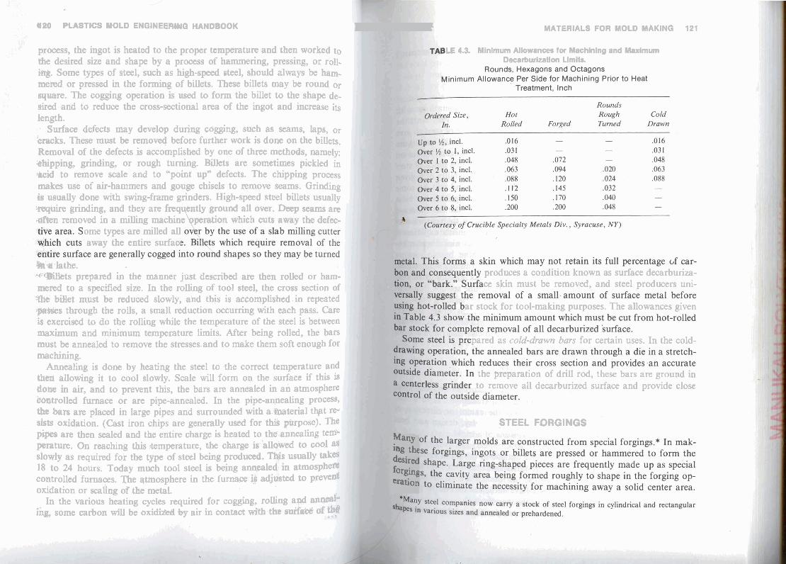
process, the ingot is heated to the proper temperature and then worked to LE 4.3. Minimum Allowances for Machining and Maximum the desired size and shape by a process of hammering, pressing, or roll- Decarburization Limits.
$R$. Some types of steel, such as high-speed steel, should always be ham- m e d or pressed in the forming of billets. These billets may be round or quare. The cogging operation is used to form the billet to the shape de- sired and to reduce the cross-sectional area of the ingot and increase its length.
Surface defects may develop during cogging, such as seams, laps, or $packs. These must be removed before further work is done on the billets, Removal of the defects is accomplished by one of three methods, namely: '&hipping, grinding, or rough turning. Billets are sometimes pickled in lacid to remove scale and to "point up" defects. The chipping process makes use of air-hammers and gouge chisels to remove seams. Grinding i s usually done with swing-frame grinders. High-speed steel billets usually . m i r e grinding, and they are &en removed in a milling machin
o m types are milled all away the entire surfa
W s lathe. - f t W t s prepared in the manner just described are then rolled or ham- produces a condition known as surface decarburiza-
rnered to a specified size. In the rolliag of tool steel, the cross section of ce skin must be removed, and steel producers uni-
She biilet must be reduced slowly, and this is accomplished in repeated +piaxes through the rolls, a small reduction occurring with each pass. Care ar stock for tool-making purposes. The allowances given
is exercised to do the rolling while the temperature of the steel is between maximum and minimum temperature limits. After being rolled, the bars must be annealed to remove the stresses.and to make them soft enough for pared as cold-drawn bars for certain uses. In the cold-
machining. Annealing is done by heating the steel to the correct temperature and
fbm allowing it to cool slowly. Scale will form on the surface if this is the preparation of drill rod, these bars are ground in
do@ in air, and to prevent this, the bars are annealed in an atmosphere to remove all decarburized surface and provide close bmtrolled furnace or are pipe-annealed. In the pipe-annealing p r o w ,
bars are placed in large pipes and surrounded with a baterial t b t re- %& oxidation. (Cast iron chips are generally used for this purpose). Tht? STEEL FORGINGS pipes are then sealed and the entire charge is heated to the.annealing te& pa t tun . On reaching this .temperature, the charge slowly as required for the type of steel being prod 18 to 24 hours. Today much tool steel is being an controlled furnaces. n e atmosphere in the furnace oxidation or scafing 09 the metal.
In the various heating cycles required for cogghg, rolling a+ a ihg, some carbon will be oxidi- %$y air fn wcontact Mth: tb ~ttiYit&
Many ing the desired forging eration

112 PLASTICS MOLD ENGINEERINQ HANDBOOK MATERIALS FOR MOLD MAKING 123
'the twhnical data furnished by
surface wrist ~s$&tiop. This MACHINABtLITY t iron chips or pit&'coke, by
, or by heating in a wuum Borne grades of steel will undergo certain machining operations with &eater ease than others. The machinability of steels may vary with the w a l i n g process. It is possible to anneal specially a piece of steel to give $$ better machinability for a given process. For obtaining the maximum maunt of machinability, steel stock from which mold plungers arc cut on &duplicator may require a different annealing process than a block of steel .
ing to which the stock has been des&nated temperature rang- hardness and to relieve the
ar machinist's experience. (such as nickel and man- , while relieving the major
sses inherent to the pro-
bartines of steel, is accomplished by heating just a b v e ule critical point and then permit-
HEAT TREATMENT kr4 'aTf&ESS RELIEVING
idud stresses. Steels that have been sub-
ons nlust,be relieved or distor-
Aftel ,- ing froq stre& from
stresses I(
cess resu by a sea
Annealin the meta ting it tn

124 PLASTICS MOLD ~NGINEERING HANDBOOK MATERIALS FOR MOLD MAKING 125
STRENGTH OF STEEL
MACH1" IYG STRESSES
HARDNESS PENETRATION
wnching solution, cools very quickly. The inner core cools relatively y. Steels that must be quenched rapidly t o give them proper hard- will have an outer shell that is hard and an inner core that is relatively owing to delayed action of the quenching. This outer shell may be to %-in. deep in a water-hardening tool steel. The use of certain al-
hing. The oil-hardening steels show greatsr hard- water-hardeping steels, while the air-hardening
the greatest degree of hardness penetration. Molds subject ection should not have a high degree of penetration.
MOLD STEEL REQUIREMENTS . .
heating during heat treat-
A p o d mold steel must be clean; it should not contain clusions which will cause pitting during polishing.
e and free from voids and porosity. ing rapid heating when the thin sections reach the critical temperature ~n#9*. It must be uniform in structure and. relatively free first and start contracting while the thick sections aR still expanding.
Figure 4.4 illustrates the advantage of slow heating, During slow heat- ing, the combined stresses aie below'the yield strength of the mold and no distortion occurs. During fast heating, the combined stresses are greater than the yield strength and the m@ld d l s t m , 'The mold cracks if corn- . Steels which machine @ly
y are needed for wonomical mold comtpction.
hardness. They are easily machined and polished to a fine for most injection molding applicatiohs. It Is advisabt to and the low alloy steels are nrqlds made from prehardened steel if the mold is comp1h"Eed Bt radii and corners.
ired hardness in
and polishing.

126 PLASTICS MOLD ENGINEERING HANDBQOKr
Stre~gth and Toughness. Molds require a hard surface and a very tough core-the larger the mold, the greater the core strength needed for resisting distortion or cracking.
Heat-treatrirg SSqfety. An important characteristic of a good mold steel is its ability to be hardened satisfactorily in a wide range of sections by a variety of methods while producing uniform results. F M . All mold steels must be able to take a mirror-like finish easily,
although a dull surface is often used as the desirable final finish. Wear Resistance. Wear resistance is a fundamental requirement of a
p o d general-purpose mold steel. Some of the plastics cause little tool wmr, others, such as the glass and asbestos-filled compounds, require the maximum amount of wear resistance.
SELECTING THE STEEL*
As the plastics industry developed and presented new materials and molding methods, larger and larger moldings were developed and the steel makers cooperated by building the larger They also provided stronger and impurities available in all the demand for mold and abrasive plastics in
Rm Steel
Rgte steel is a low carbon steel such as SAE 1020 produced by the openhearth or &her inexpensive processes, wherein cjeanliness is a less important factor WR volume. This material is used almost exclusively for the frames of molds. Plate steel can be carburized and hardened or casehardened. It k3 sometimes used to make cavities and plungers, but this application is not recommended because of the low core strength of triis stecl, and also becaub structural faults, such as pipe, seams, pits, and other defect&, are comrnoa @ it. Blate steel should not be used for cavities or plunger$ on any byt the &heapest of molds.
There are several qualities of plate steel available and if any press&re is @
concentrated on the plate, the better grades should be w k t d . s o d mold builders use the cheaper grades.of boiler plate for ckmping plat& parallels, etc., and the better grades (something like SAE 4140) for the back- ly, plates, steam plates, or other members on which stresses may be c o p centrated. This practice requires that a large inventory of stock bre carried, thmfure it will be found wiser to use the better grades of plate ftii-~ugho*
*See a h ASM Met& Handbook, 8 Ed., Yd. 1, gage 768 for additional data.
MATERIALS FOR MOLD MAKING 127
~btained by using the cheaper grades makes a negligible dif- otal mold cost, as it amounts to only a few cents on the pound. &e usually made from plate steel, while knockout bars and
made from machinery steel bars or cold-rolled steel. It is pos- , .to use cold-rolled steel, unless these , machinery steel would be indicated.
1 class as the SAE 1020 plate steel. hot-rolled into flat or square bars
these bars can be used without any pt a surface grinding on both sides to produce flatness.
which of these
it is not suitable for hobbing. of tool steel has nearly the same hardness
, and may lack toughness. As a result, the mold may r than distort when excess pressure is applied. The initial ,high. It is frequently used for injection molds because
ure as easily as other steels. rdened all the way through.
when properly applied. tool steel may he used when maximum hardness is
hen hardened, therefore ample allowance
distortion must be held to a minimum and are recom-
' STMIPARD MOLD COMPONENTS
e mold designer can save hours of decision-making selection, if he will use standard mold frames where
mold parts, which are inevitably indicated mold he may build. (See Chapter 8.)
mass fabrication facilities afforded by

128 PLASTICS MOLD ENGINEERING HANDBOOK MATERIALS FOR MOLD MAKING 129
the principal suppliers of standard mold parts assures the mold builder of king the various types of alloy steels and gives the properties economy and reliability he can not otherwise achieve, except in unusual circumstances. He can expect that the quality of the materials, and the heat treatment, if any, employed for these products are better controlled than it is possible to do in a shop with less demand and supervision. STAINLESS STEEL
He must, however, be aware of the differences and intended use of the many alloys classed as stainless steels, only a few nepd be various grades of steel available in standard &kames and plates. Besides the use in high-pressure molds. Because of the necessity for SAE 1020 plate steel mentioned above, generally supplied in an analysis up to SAE 1040, as' the lowest grade of steel, m m suppliers offer better choices the most commonly used. It contains 12 to 14% chromium for more severe service, of SAE 4130 to 4150, prehardened to 26 to 29 Rock- well C, and even P-20, prehardened to 28 to 32 Rockwell C.
Besides mold bases, and individual plates ground and sized to close toler- ances, there are !eader pins, bushings, ejector pins, sprue bushings, pre- machined cores and tool steel cavity blocks.
Other items which have been added to the ever-growing list, as demand increases, are such more complicated, heat-treated and assembled devices as; early returns (for the.knockout system), latch-lock mechanisms to deter-
mechanisms themselves. As the result of previous wide application of these devices, he can-be assured that they are largely fcrolproof when installed n iqieetion molds for t m r o h ma- by experienced personnel.
ALLOY STEELS
Nickel Toughness and strength. Chromium Hardness. Adds to abrasion resistance in high carbon compositions. Vanadium Purifier-also adds fatigue resistance. Molybdenum Widens heat-treating range and adds heat resistance. Tungsten Hardness and heat resistance.
w co: ab thc (s ha

MATAltRLS FOR MOLD MAKiNQ 131
For 1
depth c of the n Rc .
The binatio
/'
PLASTICS MOLD ENGINEERING HANDBOOK
&3 w, 18% Nickel hfar~ging &el 0.03 18.25 7.75 4.80
I &% me, 18% Nioeel Mirragbtg Steel 0.03 18.25 7.50 4.25
finished mold is then reheated to about 900°F, held for about 5 hr, and cooled in air. This treatment, called aging, results in an average hardness of 50 Rc, depending on the type of maraging steel (Table 4.6) which has been used. These steels shrink during aging and allowance must be made for this by the mold maker.
and transfer molds, the P20 mold is carburized to a
STEEL FOR. MACHINED MOLDS P6) type must be carburiwl, resulting in a good com- hardness and core toughness.
rcial low carbon machinerysteels are nearlyideal when machinability ne important consideration. These steels are usually high in phos-1 HOBS AND HOBBING
Re 30-35, where it is readily machinable. No hwt . It can be chrome-plated .when corrosion mdd'lrt:
r fmhg the mold frame. Selection
as tbt experienced with SMC. If a higher hardness is req&ed., and some -sf their prope&ies is shown b deep hardened to RC 45-50.
132 PLASTICS MOLD ENGINEERING HANDBOOK MATERIALS FOR MOLD MAKING 133
A IS[ Machinability Wear Compressive --EDGE or LAND
Raring Resistance Strength Toarghness Checking r p ~ i L ED BECAUSE OF POOR FLOW OF COMPOUND
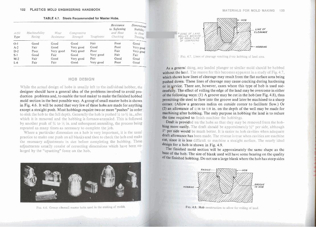
I, FIG. 4.7. Lines of cleavage resulting from hobbing of land area.
1 thing, any landed plunger or similar mold should be hobbed The reason for this becomes apparent in a study of Fig. 4.7,
HOB DESIGN
While the actual design of hobs is usually left to the indiddual hobber, the
to sink the hob to the full depth. Generally the hob is pushed % to 5 / 2 in., after finish-machine the hobbings. which it is removed and the hobbing is furnace-annealed. This is followed
by another push of !% to $4 in, and subsequent annealing, the process being d mn the hobs so that they may be removed from the hob- repeated as many times as necessary to complete the job. The draft should be approximately Go per side, although
Where a particular dimension on a hob is very important, it is the usulll be much better. It is easier to hob cavities when adequate practice to make one push on all blanks and then to check the hob and make been made. The reverse is true when cavities are machine the necessary adjustments in size before completing the hobbing. Them difficult to machine a straight surface. The nearly ideal adjustments usually consist of correcting dimensions which have been en- larged by the "upsetting" force on the hob.
FIG. 4.6. Group ohfamali master bobs usad in the d i n g of tw*. ~~on to allow for rolling of land.


su_sds eo tile! d ~ d dtM. after cold-holabing." , .,
cal Th of bla nza
MATERIALS FOR MOLD MAKING 137
m p k , lnng thought to be impossible, is W-production of @td undercuts on the side walls, such as for dewrated closures. i &lease the hob after sinking in such a situation is the result )!ad experimentatioh. It depends on the expansion of the W m from radial precbmpression applied prior to hobbing and
ingenious design of the retainerring.-
HOBBING STEELS pp ,* ':
designations, one is able to select the best potential hobbinn
&-hi* than for bobbing. ntly B M ~ for injection molds are listed inTable 4.8.
Wms of steel available, some mold makers and . I - -
T4 n s t i s r injection uaa
olds. 35. lhis Usually should used be
Iled,plastics and for
aM a h @ fQ000 F, but not higher than nw&?idimtbetilgfietthan60Rc.

MATERIALS FOR M W MAKING 139
it difficult to select the proper steel. It is e s t w that about plastics molds are made from only six types of
1 if the industry could standardize cm fewer steels. more economically in larger qua&@ inventories
ed because of fewer catem*, inereaskg maker. The heat treater's task wuld also be treatment and loner mold life.
for compressian and transfer m0Ms are
predominant lenable steels, In molds.
pk&fgs get larger, and lower prduction, in most cases, #&R 18rger moldings, alloys other than steel can often &. : -
rtous castable alloys used in molds, including proto- mbIds are: alloys of copper and beryllium, alloys alloys.
cX,bper alloys, with a basic composition of 2.5% mdoer, has been used for aver 40.vears for in-
for shape and
ting was con- i sp~ifled for
&,kith F e early machines from Europe (see & 8lld &terials for blow molds.)
the "pressure ct the molten to a hob for to push out
ing. ~dred pounds, he process in

:f,y' PLASTICS MOLD EWOINEERINO HANDBOOK I
: - ceramic pattern is used in place of the heat treated steel hob; ise.
I c Casting."
. later, improved by the application of a vacuum during the castiq I I 8, because the ceramic is unable to withstand the compactine i 8 .( ,. . used in the earlier technique, very reliable castings, virtuah I . 1 0 , ~ ~
fw, and with excellent reproductisn of the surfaces cast against, , .= available for much larger molds. When the conversion of furniture
, w h h the late 1960s occurred, beryllium casters were able to mold up , 1 , t i %a W - p o u n d castings.
, . , ., , Waay alloys of copper with beryllium are available. Table 4.10 lists the '
,&we alloys most commonly used for molds.
I ' ' &%kction depends on the desired degree of fluidity and the mold-makina
to be used. Certain alloys are for making cores and mandrels rathe1
ture. And the foundry can cast them at lower temperat @, W F). This is important when using a ceramic mold-ma
8'i+ecjing on available melting equipment. At lower tempera1 s, is As metal-mold reaction. Also, simpler foundry equipmer
the class of materials having 1,.7% or more beryllium, hi, contents give higher fidelity of reproduction. But the hi&er 4
F 1,
' -3 , 4 Eontent, the higher the cost. The 20Cand 245Calloys (see Table ' f ,&I Gammon. But the choice can depend on pattern quality. V
~txck~ent pattern 2OC will be satisfactory, alloy 245C can corn &&*kt for less pattern precision. ie m& important mold manufacturing m Q n s for u ~ h g the %

142 PLASTICS M6LD ENGINEE~INQ HANDBOOK
pressure while the metal is molten. The metal flows to conform to the shape and surface finish of the hob very precisely.
When making a hob, the mold maker must include fillets wherever
of BeCu from pouring temperature to room temperature. Shrinkage is predictable and consistent. - 1 hardness and strength. Besides machining a hob, the mold maker can some- times cast one via a ceramic casting process.
When heated, lower the chase or mold casing the hob assembly and aove the two onto a hydraulic press.
A deflector will insure this pattern of flow. When the beryllium copper hm
very important. Move a& quickly as safety allows.
the hob from the mold before too much cooling occurs. If cooling prow too far, it will be necessary to heat the hob and mold to about 1000°F facilitate separating them.
Ceramic Casting. Ceramic casting follows any one of a number of paten 4
around the pattern. The elastic quality allows stripping from t b ptq
designed part. The special ceramics u d preserve the A proper ceramic mixture will combine g o d surfam rn relatively high permeabilgy. This bst property allows %flag
MATERIALS FOR MOLD MAKING 143
sting of the BeCu around the ceramic, resulting in a sound, dense
gaming the ceramic slurry into the rubber mold, the mold maker I solidify and then fues it in an oven. He then lutes gates and risers
b c . Melting and pouring of the beryllium copper around the aern follows the steps covered under hot hobbing.
blidifiition of the metal, the caster breaks away the ceramic. xefully controls the cooling of the metal to achieve good dimen- *ces in the casting. See Fig. 4.14. ;4 )&%#oys. Where the cavity or core shape is not complex and a cast- g-$adicated, high strength wrought alloys of beryllium copper are
p ' , tube, bar and plate 'form. These may be ordered from stock &&led or precipitation hardened state. Brush AIloy #25 is one of P and most available wrought alloys. 2' -- h a t . The mold maker can heat treat a beryllium copper mold b s that the user desires. The hardenabilitv of bervllium CODD-
a befyllEitw wpper (or aluminum) mold by the ceramic castine ative (righi cavitv (lefi
w
which is then used as a IS cast from the ceramic -.
en^ Corp., Pleasantville, NY)

lrlrl PLA874CO MUIOLD ENBlIIEEERING~ HA4WWOK MAVERtALS FOR Yam MAKlNB 1.46
m&mri'%; from B80 m high #rts W on &e particular a l k y used .d aoft surfaces far-avity and core co
ng pttoperties, if loading b kept within at the higher end- d the r a w . &st# w1ut.b~ hBf trmfing and th
M@chining. After casting and h a t trmtmmt, a machining mge begins, Tfiis removes gates and risers, produces smooth shut-off surfaces betweeq
Aluminum
@a c@ fiekpjl frrc~~eds at a rate
" H. ~,'Simd;rrtEs, W i York, V d NIB-
Zinc Al
Several cially f~
, have tht and ye1 to or be
In mc which a can be L and inj Cu 3.54 gation 3

146 PLASTICS MOLD ENGINEERING HANDBOOK
dependent upon the shape of the master. For simple regular shapes, such as pen barrels, the plating can go very fast, and a wall thickness of 3/32 in. and over can be built up in a day or so. On plating masters that have a number of recesses, such as those for gears, the plating rate will generally be slower and sometimes as little as .010 in. is put on each day.
There are two methods used in the making of electroformed cavities. In one method a relatively thin layer of hard nickel is put on, generally less than 11 16 in., and the balance of the build-up is a softer nickel. The hard nickel runs around 500 Brinell and the softer nickel about 150 Brinell. Another method of electroforming, developed in England, builds UD I approximately 3/s in. of nickel having a hardness of 450 Brinell. To buili up the main mass of the cavity, copper of 220 Brinell is plated over the nickel. The copper is used because it is somewhat haFer than the soft nickel generallv used. it builds at a much faster rate. and Gt builds much more w ~
- - ---- evenly so that the many machining~ during the build-up which are usually necessary to remove the "trees" and ~ o i n t s are not reauired.
At some point during the electroforming process the master is pulled from the cavity which has been formed. In some instances, such as formation of cavities for pen barrels, the masters are pulled when the electroformed shells are about 1/16 in. thick. These masters are invariably of metal and they are started over in the cycle while the first shells formed are returned to the plating baths for continuation of the build-up. In this way a number of cavities can be made from one master in a reasonable time. On such things as gears with relatively delicate teeth, it is seldom practical to reuse the master, so the master is left in until the cavities are ready for machining. In such instances a master is required for every cavity desired.
The plating masters are made in numerous ways. A very common method is to machine them of metal. In the case of pen barrels, heat-treated stain- less steel is the most commonly used material at this writing. For gears, probably the most common material is brass. Many masters are made of plastic materials. A common method of making multiple masters is to machine them first, and from this make a cavity into which can be cast
almost no loss of dimension. Epoxy resins can also be used to cast into
I I
or molded various plastic materials. Many shapes can be molded with I'
such a cavity, reproducing the original master with considerable accuracY. ] When oriknal masters are made out of wood. leather, or other substances w
which cannot be put into the plating bath, they can be reproduced by making a cast over the original master and casting back to reproduce the original master in the desired plastic material. If the proper materials and techniques are used, no discernible loss of detail will result. 1
MATERIALS FOR MOLD MAKINQ 147
lications of electroformed cavities are numerous, but it is difficult ral rule as to when they are indicated. A slight change in will indicate that a cavity should be made by electroforming
machining, hobbing or casting. A frequent reason for electro- presence of delicate detail in a cavity. Since the electroformed reprodues the finish on the master no polishing or other
. Electrofonned cavities are frequently used because of can achieve. A brass master is simple to make and easy
ensions. Electroforming cavities will exactly reproduce the on the master. When mbdels are available, very often an
cavity is cheaper because the model can be used for the and no metal form is required such as for casting or hobbing.
K'JS- EIeBrnformed insert of large mold for clear plastics drafting instrument. All hv mmbers and letters are raised on the mold surface. This mold insert would be k m o u l t to make by any other process. (Courtesy Electromold Corp., Trenton, NJ)

148 PLASTICS MOLD ENQINEERINQ HANDBOOK MATERIALS FOR MOLD MAKING 349
Electr~forming is an economical way to make cavities with raised details, Rg. 4.15, For example, in the making of molds for speedometer or clock dbb, a piece af bram can be polished and then engraved with the numbrs, Solution
ead the eleetroforming performed over this. The result is eledroformed avities which have the numbers raised from a highly polished surface, .006-.010 "/in. and no further work is necessary. Cavities with delicate and undercut detail em side walls can be made.
0 t h methods and materials are available, usually with the result of mink cast) -008 ,008-,010 Some alloys Before mach'g. b s iwnimq, to make spur gear cavities, and even helical gars, but when
.000-.002 No -
TOOL STEEL CASTINGS*
cate makd components in multiples are economically 1 steels on a custom cast basis, and are therefore and thermoplastic materials. The suppliers use
pmess to reproduce the original master patterns, similar & Wt used for the production of beryllium copper casts,
wka %$j@img $0 wae it shs me: 142. In preparing the master, the mold marker must pt(pk@d method. Tlpes of a e ceramic cast, the tool steel, which has a dif- for "b#mce, with hobbhg. at gf beryllium copper, and of course the molding
c material to be used.
vailable, which are so far only suitable for ther- "molded" using powdered metal technology.
y the 3M Company, and while some details of the
Wliug Green OH.
-

150 PLAITICS M a B ENGlMEERiNG HAbYDIBOOK MATERIALS FOR MOLB MAKING 161
of c-tiags i& Otellitea, which is incsrpomd in a matrix of a copper alloy, persion of carbides. The wW% combbation, in the form of the same way a& would be used for the s t e l alIoy involved in
very fm pow a % er is compacted around or in the "replication" of a master, . The dimensions normally increase slightly on heat-treating which the mold maker prepares and fu rnhw, Only one master is necessary, regardless of the number of cavities needed. The limitations are: (1) size-generally not mre than 9 square inches at
the parting line of the cavity itself; (2) proportions-not more than a 4: 1 ratio of depth to minimum cross-section dimension; (3) surface f ~ s h - 2 0 to 25 microw as furnished, with the possibility of improving this to 4 mi- m n s by polishing; (4) apparent hardness-Rockwell C-41, which is ac- t u d y deceptive on the conservative side, since the composite includes Stel- lit# d carbide particles, both of which by themselves have a hardness of Rockwell C-58 or m
idweat in tb test mvhy is @@&I
&&ar ~ e e d be allowed for.
aiMyds of the &mposite: 'I CaWt 35%
PLASTICS MOLD CAVITIES
isls are used for "molds" made of plastics materials. One rsnd widely used is the room temperature.vulcanizab1e
Physical properties: Tensile strength , 110,NlQ to 140,009 psi oun'd reproduces fine details, very accurately and,
'Compression strength , 220,000 tct ~ , 0 0 9 psi undercuts will be no problei. Modulus of elasdcity s epoxy glass, urethane, polyester, etc., are then cast Apparent hardness
Another type of P/M mold co pa& of J m w t c m n p l ~ l y di @f Feasa-Tic*. Originally W rounds and
i
TREATMENT
Stellitee is a registered Trademark of the C variously as "Custom Cavities," "Replication
Perm-Tic* is a registered trademark of Alloy NY.
9% 3f tl RTF mad tech beca
Ci in tk mad prot can as t
Upon cc cumstar Protecti, not, shc many a

152 PLASTICS MOLD ENGINEERING HANDBOOK -
Parn. to i- mck Q R ~ mistana.
Any rpctnl Peem cp, FWYC f k q ~ j ~ ~ t c h e s & tool marks.
~ ~ 2 n d ~ceoraie or *texnrJCTmAid suflaces
every instance, a procedure lower in the table can be followed by one pre ously mentioned, if applicable to the same metal.
Tungsten Disulfide' ! Ahmrinum
permanent, as for the graphite process described below.
bricative mating* developed for metal P r d d ~ t y itlcmses of 10 to
*Diversified Drilube, Inc., ~ r h s a , OK. Co., Mauntain View, CA.
Fhoi
Nitn

154 PLASTICS MOLD ENGINEERING HANDBOOK
are reported from thermoplastic molds treated by this process. Mold sur- faces to be treated by this process are treated with a binder and then exposed to a high pressure (120-130 psi) spray of ultrafine graphite particles. This pressure spray impinges the graphite onto the tool surface to a depth of 0.0002 to 0.0004 in. A surface coat of .00008 in. builds up on the surface of the mold component. Lubricative plating may beapplied tochrome-plated surfaces. However, to restore size and polish, surfaces must be buffed.
Chrome Plating Many molders have found that chromium plated molds are a great asset and specify chrome plating on all mold cavities and plungers. Chrome plating is also used in mold repair work for building up worn sections. This requires a cleaning tank, an etching tank, a plating tank and a final cleaning tank. An electroplating generator and facilities for building up the anodes, as shown in Fig. 4.18, are also needed. Chrome plating equipment is very useful in the hands of an experienced workman. Plating specialists do this work for the small tool shops. See also Chapter 3. Only a few platers* are equipped to chrome plate nitrided surfaces. **
\ Electroless Plating
As used on plastics mold components, electroless plating is nickel plating. Electroless simply means that no electric potential is applied to the bath. The result is a much more even deposit-no undesirable extra build-up on sharp corners, and nearly perfect penetration into recesses. Furthermore, if one of several patented baths is used, the deposit may be hardened after plating by baking at 750° F.
The softer nickel deposits and even electroforms which average Rockwell C-50 can be protected against scratching and wear by hard chrome plating, if desired. Chrome plating bonds better to nickel thandirectly to steel. (Nickel bonds better to steel than chrome does.)
Besides the obvious situation where electroless nickel is used for molding surface protection, it is extremely valuable and unique in use for protecting the surfaces of the mold frame itself, including the drilled water lines, from corrosion resulting from acid conditions in the water and condensation on other surfaces from humid atmospheres combined with refrigerated water. Accordingly, the rear surfaces of cavities and cores, including "0" Ring grooves and cooling holes, are improved by electroless nickel plating.
*Nutmeg Chrome C o p . , W. Hartford, CT. **Armoloy Cop.--Various Locations.
MATERIALS FOR MOLD MAKING 155
156 PLASTICS MOLD ENGINEERING HANDBOOK MATERIALS FOR MOLD MAKING 157
of the steel, and if suitable elements are present, combines with them to form the very hard nitrides.
Steel containing aluminum in small percentages, such as 3% is particularly . suitable. Otherwise, steel containing carbon of at least .4%, together with
chromium, vanadium or molybdenum will respond to the treatment. Molyb- denum is especially beneficial in the alloy since it reduces the characteristic brittleness of nitriding.
The normal depth of penetration of .003 to .005 in. is obtained in 12 hours, but it takes 72 hours to get penetration of .015 in.
Of the steels listed in Table 4.8 (for injection molds) the following can be nitrided: P-20, H-13, and 420 stainless; of the steels listed in Table 4.9 (for compression molds) H-13 and S-7 are nitridable.
An excellent steel, besides the through hardening Nitralloy Series, which yields optimum nitriding, is P-21. It contains aluminum and if it has been solution heat-treated as is normally done for use for molds it will age harden as it is being nitrided, to a core hardness of 38 while the surface is 70 Rock- well C.
THERMAL BARRIERS FOR MOLDS
As molds go up in temperature, a point is reached where the loss of heat going from the mold to the pre&''platen cannot be tolerated. At ordinary mold temperatures, this problem is often minimized by multiple channels in the clamping plates, giving the effect of minimum heat transfer areas. Transite* asbestos sheet is commonly used in the intermediate temperature zones where dimensional control across the parting line is not critical. For highly accurate molding with absolutely flat and parallel press platens, glass- bonded mica,** a machinable ceramic is used because of its low thermal conductivity and its absolute dimensional stability. Glass-bonded mica can be lapped to an optical flat and will hold it indefinitely. For Situations where thermal barriers must be of minimal thickness, Nomex*** sheeting is pro- portionally effective. For localized areas where high physical properties are needed, alloys of titanium may give some relief.
POINTERS
In case of doubt, use a type of steel which is better than the one You might select but are not sure it will be satisfactory.
*Transite, Johns Manville, Greenwood Plaza, Denver, CO. **Mykroy, Mykroy Ceramics Company, Ledgewood, NJ.
***Nomex-E. I. DuPont de Nemours and Co. Inc., Wilmington, DE.
Don't specify a hardness in excess of that recommended for the steel used for the particular application. In general, more molds are lost by :racking than are worn out by use. Always double temper after hardening any steel, and if the hardness is too high after the first tempering, double temper at a lower tem- perature. Don't expect plating to cover surface defects or to improve polish; plating exaggerates pits, scratches and blemishes. Don't,try to cover up cracks by welding. If the crack is not too extensive, cut it all away, and build up the weld from sound structure. Do not use nickel plating in contact with rubbers containing sulfur, nor chrome plating in contact kith chloride or fluoride plastics. Go over the sharp corners of cores and cavities after chrome plating and check for excessive build-up which may interfere on fitting and on sliding surfaces. Excessive compressive loads can result at the parting b e s when clamped. Failure to do this may result in chipping of the chrome. Watch for,''white layer" embrittlement from EDM operations on molds. There are ways to avoid this problem: (1) Slow down final EDM opera- tion at the end, using low amperage. (2) Inspect for "white layer" and polish away. (It is seldom over .0001 or .0002 in. thick.) Check with your chrome plater to be sure he takes precautions against hydrogen embrittlement. Bake chrome plated parts 375O F for an hour, before putting in service or applying stress. Take advantage of the maraging and precipitation hardening steels; while being nitrided, these age harden to improve interior structure and hardness. Remember that nitriding is theoretically an irreversible process while through-hardened and pack-hardened steels can be annealed; chrome and nickel plating can' be stripped. DO not subject a steel to a surface treatment that involves a temperature higher than that at which it has been tempered. Often, molds are "tried-out" before they are plated. Do not try out molds for corrosive or highly abrasive materials, unless they have been plated. It is better to repolish lightly a mold that has had to be stripped of its plating in order to make corrections, than to have to remove a substantial amount of metal because of corrosion. Where metal slides on metal, select materials and heat treatments for the two components so as to obtain surfaces having hardnesses separated
at least six or eight points on the Rockwell C scale.

158 PLASTICS MOLD ENGINEERING HANDBOOK
REFERENCES
Alcoa Aluminium Handbook, Pittsburgh, PA: Aluminium Co. of America. Bengtsson, Kjell and Worbye, John, Choosing mold steel for efficient heat transfer, Plastics
Machinery & Equipment, Aug. 1984. Hoffman, M., What you should know about mold steels, Plastics Tech., p. 67, Apr. 1982. Properties and selection of metals, in The Metals Handbook, Vol. 1, Metals Park, Cleveland,
OH: American Society for Metals. Heat treating, cleaning and finishing, The Metals Handbook. Vol. 2 , Metals Park, Cleveland,
OH: American Society for Metals, Cleveland OH. Revere Copper & Brass Publication, New York: Revere Copper and Brass. Shimel, John F., Prototyping: How and why, Plastics Design Forum, p. 7 5 , Jan./Feb. 1984. Stahlschlussel (The Key to Steel), Metals Park, Cleveland, OH: American Society for Metals.
Stainless Tool Steels for Molds, Uddeholm Steel Corp., 1984. Tool Steel, Simplified, Philadelphia, PA: Chilton Publishing.
Worbye, John, Polishing Mold Steel, Plastics Machinery & Equipment, Feb. 1984.
Design Drafting Enginee Practice
I Revised by Wayne I. Pribble
designers and tool draftsmen follow many general rules which ex- has shown are both practical and desirable. Some of these rules n established as standards for the preparation of mold drawings; who follow these rules avoid many of the troublesome and un- ry mold designs which result from neglect of fundamentals. This
was prepared to detail the principles and rules of design which, ny years, have been found to give the best results. Understanding rules and intelligent application of them will help the draftsman
uce drawings that will convey his design to the toolmaker in such that he may interpret it readily with no possibility of misunder- . It must be understood that the rules given here are general in
ation and are to be interpreted with regard for the special con- existing practices of the shop where the tools will be designed,
usfd. The mold designer must familiarize himself with his own ice and learn what limitations will modify the application of
are the permanent record of a design from which many copies
mdamental requirement of a drawing is that it shall give the neces- biafomation accurately, legibly and neatly. The tool-maker's first

160 PLASTICS MOLD ENGINEERING HANDBOOK PLASTICS MOLD ENGINEERING HANDBOOK 161
measure of a draftsman's ability is based on the neatness and legibility of the print which is furnished him. His final evaluation is made on the basis of the accuracy of the drawing. A drawing may carry as many as 500 dimensions and, of this number, only one may be inaccurate, but the instead, have a print damage done by that one wrong dimension can far outweigh the good of 499 that are correct. It is impossible to emphasize too strongly the neces- sity for accuracy in all dimensions and for clear presentation as well.
There is a common and very correct tendency among draftsmen who have worked for a period of time in one place to leave some items to "shop output of a computer program. The size and type plotter used practice." This may include such things as clearances, tap drill sizes, tapped holes, etc. The consulting designer and the designer of molds which may be built in any one of several tool shops cannot do this to any large extent because plastics practice is not standardized. "Shop practice" varies widely among molders, and the molding shops where the molds are designed and the men who build the molds may be several hundred miles apart. available for draw-
At several points in this text, the use of standard mold bases is detailed. selected by the de- Wherever possible, we recommend the use of these highly specialized in advance, to op- components, and once again, we recommend that the designer keep a com- lar plotter. The usual choices available are: 1) plot what plete file of'catalogs for these standard mold bases and standard mold nitor screen; 2) plot to size; or 3) plot to scale. Item 1) is components. (See Chapters 3 and 8.) Duplication of these catalogs in this text would serve no useful purpose. However, we do show designs based used in a reference upon standard mold bases. Bear in mind that cost is an important factor ws for each screen in today's economy where the wages of the mold-maker represent a sig- nificant part of the overall cost of a mold. The mold bases are built as complete units by tool shops that have the varied equipment needed to fabricate these units. This equipment includes large grinders, tape con- trolled mills, jig borers, and similar equipment, all of which is referenced ause of variations in Chapter 3. Figures 8.92, 8.93A, 8.93B and 8.94 cover the utilization of se here is to alert standard mold drawings to simplify and shorten mold designing time, as applied to injection mold design.
Tracings of their software package. A manual will (or
A tracing is a form of drawing used for making prints. Prints are the copies n on plotter configurations and operation. Of of the drawings (or tracings) used in the shop as a guide in the construction at you dould also ask, "Who else is using this sys- of the mold or product. Most draftsmen make the drawing directly on tracing paper or tracing cloth. Others make the drawing complete and then prepare a tracing from the original. A tracing is never used for manu- facturing and should not be used for reference purposes. The cost of re- tracing is high and the draftsman must see that the tracings receive proper care and treatment. Tracings are easily damaged by careless handling, therefore the following rules should be observed: i& on a screen made up of rectangular pixel

4 - CA V/ T Y SEM/AU TOMA T/C MOL D CASSEMBLYJ
FOR SW/TCH COVER C-/023
;.sad ~r mw @/4&l I ~ . . . BMc B d f ~ T-402381
162 PLASTICS MOLD ENGINEERING HANDBOOK
shapes. However, a plotter is designed to plot a straight line from A to B, or to plot a circle in very small increments so a true circle results. In any case, we recommend the selection of a plotter based on the usual size of should follow the rules of Orthographic Projection. In the
your output drawings. Plotting is the final step for which a design is created. Thuspaper, vellum
or transparent film are choices for the final plot. The choice of plotting medium will also determine the type of pen needed for the plotting. If a one- time use in the tool shop is all that is required, paper will be satisfactory. Plots to vellum are usually used when it is desired to have a permanent plot from which prints can be made as needed. A plot to a transparent vellum or film should be made because the cost of making a print from a transparency is low compared to the time and cost required to make multiple copies of an individual plot. The choice of transparent film is dictated when accuracy of the plot is essential, such as in automotive panels, where scale measure- ments are taken directly from a plot or drawing. This scaling practice, while common in automotive applications, should only be done when it is clear omitted except'where it is considered necessary to clarify that the designer intended for the final plot to be used in that manner. In other words, a print should never-repeat-never be scaled because handling and humidity conditions can distort paper images.
tions or to ask questions. Tabulation of dimensions ntle in the actual preparation of drawings, as the possibility
reading is greatly increased thereby. The complete part and i uld be drawn before starting to dimension. This practice I Y
erasing and give cleaner and neater prints.
1. Size of mold (number of cavities). 2. Type of mold. 3. What the mold will produce. 4. A serial drawing number. 5. The names of people who worked on the drawings a ~ d the dates on
which the work was done. Names must be written as signatures. Standard abbreviations may be used for the months, but the months should not be designated by number.
FICA 5.1 Typical title form.
sent ; ti h 0
C
U
fl tl s
PLASTICS MOLD ENGINEERING HANDBOOK 183

164 PLASTICS MOLD ENGINEERING HANDBOOK
General Rules of Drafting Practice
The following suggestions are given for the purpose of presenting those fundamentals considered essential to good practice. Observance of these rules will serve to avoid errors commonly made in the design of molds.
1. Do not try to second guess the product designer concerning his actual needs in the final molded part. Refer all questions concerning insufficient detail or information on the product drawing to the responsible design engineer. Always secure authorization in writing for any changes that you believe will improve the product, reduce the cost of tooling, reduce manu- facturing cost, or prevent an actual error. The best procedure is: to mark up three identical drawings showing everything that you have used or as- sumed in designing the mold-this includes suspected errors, unclear in- formation, ejector pin locations, gate locations, drafts, tolerances and requested or suggested changes, then send two marked copies to the pur- chasing agent who handled the buying of the mold, and ask him to return one marked print with the design engineer's approval or comments. Al- ways retain file copies of these negotiations, including the final approved print to which the mold is designed. Correcting or rebuilding a mold built to unauthorized deviations can be very expensive, time consuming, and frustrating to the customer.
2. Check the product drawing very carefully before mold design is be- gun. Redesign the product completely when necessary to make sure that the piece can be molded consetently and satisfactorily with the produc- tion methods and materials ava~lable.
3. In cases where the estimator specifies the mold design that was used as the basis for his quotation, make sure that this design is followed unless approval is given for deviation.
4. Long slender cores and mold sections should be designed as mold inserts when they cannot be eliminated by a change in the product design.
5. While positive draft is the usual practice, do not overlook the use of zero draft or negative draft when their employment may be helpful.
6. Be sure that connections for temperature control media, and the thermostat locations do not interfere with clamps, clamp bo:ts, strain rods, ejector rods, or other parts of the machine or press for which the mold is being designed. Make a note on your assembly drawing specifying the machine or machines for which the mold is designed.
7. Be sure to allow ample clearance between drilled holes for the tern- perature control media and the adjacent holes for ejector pins, screws, guide pins, bushings, etc. One-fourth inch is the minimum with which mold- makers like to work (carry a special note if it has to be less than % in.). For holes in the 12- to 20-in. range, use % in. clearance. Use proportion all^ greater clearance for longer or deeper holes where steam, oil, or water is
buil the
I ( for drab
PLASTICS MOLD ENGINEERING HANDBOOK 165
(electric heaters can be close to adjacent holes with no prob- kage of media). Look up other references in this text for infor- heating and cooling channels.
8. Rbmember that most thermoplastic materials require large degrees of b l i n g . However, many of the engineering thermoplastics require heating the mold. All the thermosets require heating the mold.
~hermosetting materials are not quite so critical in relation to tempera- 1 of the mold. However, urea and melamine materials require
for best results in molding. Give special nneling in all molds where maximum production is re-
not difficult to calculate temperature needs and the heat trans- needed in a mold. Time spent in a calculation will pay dividends. As a
empirically state. that it is almost impossible to over a mold. In any case, over channel is to be preferred to under
of rapid conductive metals, such as beryllium copper, hodd also be considered. Channels in long slender core pins, is called
Considsf also the use of heat pipes* which will either heat or cool urce. Air jet cooling is also frequently used, where other
cult or impossible to use. se of standard lengths of screws, dowel pins, and guide pins ible. Small deviations from these standards cost money.
10. Specify the type or kind of steel for all hardened mold parts. Call ame or type of steel to be stamped on the back of the mold
tice will give the heat treater essential information if it to anneal or rework the piece.
ntion to any unusual features or important dimensions meam of notes, so that the tool-maker's attention will be focused on
nts. Tangent radii, negative draft, or special, sharp cor- ardeniqg or tempering to be done, must be plainly indi-
. not deviate from standard design practice unless at least one r ewrienced designer has agreed that the changes will improve the ation @f the mold.
methods used in the tool shop where the mold is to be t SQ lhat the mold can be dimensioned in the manner best suited to equ@ment available. 1: designer should, when possible, indicate the method of setup ma&hing by the manner in which dimensions are placed on the
- @W the important dimensions in three-place decimals. Show the nces snly where required by close tolerances on the product draw-
eatbank. Hughes Thermal Products Div., Torrance, CA (and others).

166 PLASTICS MOLD ENGINEERING HANDBOOK PLASTICS MOLD ENGINEERING HANDBOOK 167
ing. Be sure all close tolerances are actually needed, and that those spwi- ter Aided Design (CAD) fied can be met. Give the tool-maker no more than 50% of the tolerance allowed by the product drawing. osen should use a minimum number of operating com-
16. Where involved calculations are required to determine the centers ich can be used from on-screen prompting as opposed to constant of radii, hole location, contours, etc., preserve your figures and record to a manual. For the experienced mold designer, a CAD program them in such a manner that you can recalculate the dimensions easily a I e same general technique of drafting as is followed using pencil, T- few weeks later when changes or checking may be required. and triangle will be most quickly learned. Look for and select a
17. When checking dimensions, do a thorough job; assume that all which is also compatible with a digitizer tablet and dimensions are wrong until you personally prove that the calculations arc hich allows maximum speed of selection and operation. correct. should be restricted to specific dimensions or specific text.
18. If an error is discovered in a dimension, fmd out, if possible, wha ljrograms in current use allow for automatic dimensioning, thus faulty reasoning produced the error. ntry of dimensions should be rarely needed. Every keyboard
19. Expect to make mistakes, and check every detail to find them; avoid 1 ial for error, as is proven by the number of retypings needed making the same mistake twice. A mistake on a drawing is only a potential ct copy for this book text. loss, but it becomes a real loss if it goes into the toolroom undiscovered, cases where the designer is fortunate enough to have a CAD thus causing faulty construction. ay become fiart of his duties to predraw many of the
20. Check the daylight opening in the press to be sure the molded part hop standards (above). We have also encouraged the can be removed from the mold. Warning: some daylight figures given by
' ulations, checking dimensions, developing standards,
press manufacturers include maximum stroke. Others use maximum day- e following text are three check lists. We particularly direct your light plus stroke. Be sure you known which is meant. to the designer check list covering moment-by-moment decisions
of the designer. As you become familiar with CAD systems, it will ecorhe evident that many of the cautions and choices will actually
me selections from a data base which is part of developing your own Shop Standards system. The CAD system allows drawing once, checking once, then
Each design section should compile all of the data which define its shop over and over as component parts of a total design using a copy or
practice and any other standards that are followed consistently. These ge command. Currently, much of the data for mold bases and com- pads, such as plates, guide pins, bushings, hot nozzles, etc., are part
standards will include such items as: le from the vendors of these items. 1. Molding press data showing capacity, mold-size limitations, day t item 4, of the designer check list, arid you are per-
light opening, auxiliary rams, ejector operating mechanism, clamp ith a CAD system, you will note that with a CAD ing bolts, pressures available, and the location of holes in platens. paper size is made at plot time. (Refer to plots earlier
2. Material stock lists showing steel sizes in stock or readily available. a D system, page size (do not confuse with paper 3. Drill sizes and tapped hole specifications. me. A rule of thumb is to use the smallest page 4. Standard insert design and sizes. show the overall of the design to be drawn. It is 5. Technical data on plastic materials showing shrinkage, bulk factaf3 er he shows all necessary views on one page, or
density, draft angles, etc. arate page for each view. In the latter case, the pages 6. Spring charts showing sizes and capacities of springs commonl~ d to one page, then plotted on the desired paper size,
used in mold construction. be plotted on the same paper by specifying size and 7. Mathematical tables and formulas. 8. Factual data on shrinkage (transverse, longitudinally, dkmet* hat a 12 to 19 in. monitor screen allows only a certain
nt of observation at any one time. Using the zoom feature found in all detail can be enlarged for easy drawing or view-
monitor will be available, otherwise the 200 to 2000

168 PLASTICS MOLD ENGINEERING HANDBOOK PLASTICS MOLD ENGINEERING HANDBOOK 169
layer capability of the CAD program will be almost useless. Color monitors also assist in visualizing depth and shape just as colored pencils were fie- quently used to color-code a complicated part drawing to effect a 3-D image for the mind.
Well designed and documented CAD software will follow the sequence of items as called out in the designer check list. However, many of the required items will have been predrawn, either for the current design or available for copying from the source disk (remember-draw once and use it over and over?) For example, assume a 64 cavity mold design for a T- shaped part. Orientation for gating is four groups of 16 cavities each with the gate at the bottom of the T. By predrawing the T-shape and filing or saving it as a pictorial item, the CAD system allows copying the predrawn item, orienting in any direction, mirror imaging, scaling to any size, and placing the image in an exact position on the page as many times as desired. compare the one at a time indicating one each of 4 different orientations-and that may be adequate. One tendency when using CAD is to overdraw by adding more detail than is necessary for any given item. For example, let us assume ten screw lo- cations are shown in a plan vie Only one screw need be shown in a front or end elevation, but CAD plants a picture of a screw length. Thu
1 the unwary dl suffice. Alwa
Hopefully, made on the basis of ease of operation, simplicity of command structure and speed of execution. Some software uses 150 or more commands, whereas other software may use only 25 or 30 commands as on-screen selectable ,
choices. Most of those CAD programs using a large number of command8 will be run with a digitizer tablet with cursor control. Regeneration to the monitor screen is a function of hardware, but it should be quite rapid m ' avoid operator waiting time. Finally, we recommend a CAD program whid uses precision to 6 decimal places. Most NC (Numerical Control) equipment
1 requires accuracy to four decimal places, or else it will reject the wmPUb tation or entry.
The use of CAD is ~roiected to grow at an ever-increasing rate. currently! , any particular useable much cence of the old technology. Thus, we encourage selection of a CAD gram which will be periodically upgraded by the supplier at iittle orno to the user.
We forsee greater use of microcomputers replacing the drafting boa&.'' the 1980s. Several compaoid now offer the detailed analysis of any p 8 d ular part as a service to end umF,'lllbl(l designer, mold maker or ~ 1 d
ral colleges and universities have already installed quite sophisticated ,systems (the million dollar type) and offer courses of instruction. They ~ f f e r connect-time to local users who only occasionally need such ser- 8s finite element analysis to determine the adequacy of such items as ~ t h , impact resistance, and flexibility. Material flow analysis, ther- mamics (heat exchange) in the mold, or 3-D modeling for aesthetic f,l are other services available through these on-line or walk-in services. p n t the desirability of having all these "goodies" at your fingertips, & cost of an infrequently used feature is seldom justifiable to manage- i
k!: ENGINEERING AND DESIGN PROCEDURES
'neers and designers follow some kind of orderly routine in the of a mold. We recommend this practice and offer the follow-
ists to assist you in theprocedure. Obviously, there must be a ween the eng design. The ~ld and the n
eer lgil rted
designer :sponsibl~ For this
vho for :ea-
e check lists are supplied. The first list covers the preliminary usually made by the responsible engineer. The second list cov- oment-to-moment decisions to be made by the mold designer,
third list covers the final answers and follow-up usually performed that the mo ze himself w
of these decisions.
ING CHECK LIST (preliminary to design)
lgner reasc
,ho aspirc ling that
To Do Done
p w all correspondence, qvotations, orders and other data .
may have any bearing on the part application or mold design. - - Vise customer of any changes needed to bring the part into
ortnance with quotation. E -- r and number.
b h heating or cooling system. , --
--
-- rial chosen to be sure it is satisfactory and useable
-- -- --
, two-stage ejection, double ejec-

170 PLASTICS MOLD ENGINEERING HANDBOOK
ENGINEERING CHECK LIST (Continued) To Do Done
12. If transfer or injection, establish gating areas and specify type of gate. -
13. Establish mold venting points. - 14. Establish mold finish required by customer, by material chosen,
or by method of molding. - 15. Establish draft angles to be applied. How much and where? (don't
forget negative draft is useful). -6. Engineer review items 1 through 15. Secure customer's approval
where needed. 7. Engineer discuss with designer.
18. Establish shrinkage factor (transverse-parallel). If, thermoset, is post-baking a requirement? Have you allowed extra shrinkage?
DDIGNER CHECK LIST ?V! r .- 1. Review the preliminary engineering check list (with the engineer,
f, . 4: :: if possible). Do you understand everything? If not-ASK.
.&; ' 2. Review the catalog data on Standard Mold Bases and Compo-
.a- nents to select the most economical group of components for
7 . the proposed mold design. Can you use a complete mold base?
,;!I , Will you have to build up from standard plates? Can yo\] use . A < standard components? Will your supplier 'start from scratch" *. +., .. with raw steer! (See also Chapter 8.)
,- , 3. Answer the following questions: , '% at (' A. Where can "pickups" be placed if : I , ' is a deliberate undercut.)
B. Are inserts to be molded-in or assembled after molding? In any case, get a copy of the insert drawing. lns~st that inserts not
t. be made until after the mold is deslgned (when the inserts are to be molded in.)
, C. Are side inserts necessary and, if so, how are they to be J' supported?
D. Are wedges or side cores required? removable or captive? ' E. Where will wedge split line (parting line) be located? How
operate wedge or side cores? F. What type of insert pins are to be used and how will inserts
be held on the pins? G. Do mold pins spot holes? Do they butt in center? Do they
enter the matching section of the mold? Where will mold-maker want radil for ease of machining? Will customer permit it? Where will mold-maker want sharp corners for ease of ma- chining or reducing cost? Will customer permit it? Will the cavity be hobbed, machined, cast or electroplated?
*'&. Can or should the cavity (or core) be made in one piece? mpc Where are inserted sections needed? ''7 ]t. Where are the high wear areas in the mold? Should they be - inserted or backed up with hard plate
cation needed or provid
To DO Done
- -1
PLASTICS MOLD ENGINEERING HANDBOOK 171
ER CHECK LIST (Continued) To Do Done
IW you are ready to select drawing paper size. Is size selected ge enough to show all needed views without crowding? using a standard mold base (or plates) draw in the complete )Id base outline including location of guide pins, screws, return IS, etc. not done in Item 5, do so now-layout horizontal and vertical iter lines. Be sure to allow ample space for all views and details. yout cavity arrangement prescribed (circles-square-rectan- lar). Will spacin allow temperature control media channels? tablish ejector s f stem to be ready for item 10. yout one molded part of each configuration in plan view and in force and cavity outlines.
M ejector pins (or system established in item 8). injection or transfer mold, establish sprue; runner and gate es and the material route from nozzle or pot to cavity (do not
kt runner, runnerless, hot manifold, hot tip, etc.). ,...,.,ion mold, establish land a rea , loading well depth and
$ty wall thickness. - . ;fer mold, establish pot and plunger size (transfer chamber) e (if needed), runner size and path, and gate size. matic compression mold, establish land areas, loading ipecifications and part removal board specifications. the center line and size of the temperature control media Is. n guide pins, return pins, screws, and stop pins. Use ample r of screws with calculated holding power to resist stresses. :miner plates, clamp plates, width and length of ejector rallels and stop pins. the top layout (plan view) to front and side views to de-
~ ta ine r plate thickness, length of screws, etc. NOTE: One late i i better than two thin ones. If a long running mold, d or prehardened plates to back-up core pins, forces, cavi- l slides (see 3(L)). ~pport pillars or parallels. U& adequate support to prevent rgging under pressure. n sprues, runners, gates and ejector pins. lion all views and parts as required. trt numabrs, material list and general assembly notes in- , mold number, part number, operating press data, etc. cavities, forces, core pins, wedges, slides, side cores and :r parts requiring detail drawings. (Shop practice will de- : this.) a steel trade number or identification on a non-working of all hardened parts (in event of later modifications re- hkat treating or annealing). tolerances'where needed to assure compliance with prod-
nents. heck all drawings for dimensional errors or reversal

172 PLASTICS MOLD ENGINEERING HANDBOOK
DESIGNER CHECK LIST (Continued)
27. Review the engineering check list (preliminary). Have you done everything as specified? (Vents are most often overlooked.)
28. Be sure your supervisor, checker, or tool engineer knows all the httle assumptions, changes, additions or.deletions you have made. If necessary, mark another product drawing to show all these things and dellver to cognizant engineer.
29. Check all drawings just once more to be sure: (a) that mold can be assembled. (b) That, when assembled, all parts are in proper orientation with
each other-right hand to right hand and left hand to left hand-and
(c) that mold willjir and operate in the equipment specified or ~ntended.
30. File your notes. File all information obtained from others. File all unusual calculations for future reference (or for checker).
31. Deliver final prints to mold-maker.
ENGINEERING CHECK LIST (Jnal)
1. Review the preliminary check fist (engineers). 2. Review the designer's check list and the tool drawings. Has he
done everything according to your instructions (or given good reason for not doing so)? ', Has he told you (and supplied mab ed product drawing) about his assumptions, changes, deletions 05 dif~ons?
3. Get final approwl of customer on final % co @ration. 5. Review projected areas or mold, material volume capacity of
equipment and molding material limitations. 6. Issue special instructions for mold set-up and operation if design
warrants. 7. Review entire project with production, tool department, quality
control, set-up, and management personnel. 8. Plan for fixtures or special installation of mold well ahead of
scheduled mold delivery. 9. Follow mold progress at regular intervals of mold construction.
10. When problem arises, take necessary action, and repeat as needed. I I . Open the mold and visually inspect same before mounting in press. 12. Use thin paper and ask for a paper impression of the mold under
pressure, and before attempting sampling or production. 13. Review upon completion of sampling and advise interested parties
of adequacy or inadequacy of design and engineering. Note spe- cifically any areas of trouble.
14. Finally, ask what can we learn from this project that will be useful for future mold designs?
PLASTICS MOLD ENGINEERING HANDBOOK 173
DIMENSIONING MOLD DRAWINGS
desirable to follow the rules of good practice when dimension-
a center line indi-
-- To Do Done
- -*
- 315 (SEE SECTION A-A J' NO DRAFT ON TW/S SECT/ON
15 (SEE PLAN VIEW)

174 PLASTICS MOLD ENGINEERING HANDBOOK PLASTICS MOLD ENGINEERING HANDBOOK 175
6. Enter all esiwntial dimensions on every drawing. It is bad practice to permit scaling of prints, since the printing and drying process may in- troduce considpble distortion.
7. Keep all related dimensions together so the tool-maker will not need to "hunt" for the dimensions he needs.
8. Try to keep the dimensions between the views as much as possible. ts. Tolerances on mold dimensions are required because of the 9. Dimensions given for length of thread, depth of tapped hole, etc., are nal variations that occur in machining, hardening, polishing,
generally understood to indicate the minimum length of the full thread, Tool-makers will make the required allowance for the thread ending.
10, Use three-place decimals for all ordinary cavity and plunger di- mensions, four-place decimals are used only where the extra accuracy is essential, or where it is necessary to make the component dimensions "add up." Use fractions or two-place decimals wherever ordinary scale dimen- sions will suffice.
I I . Numerals and figures on tracings must be heavy enough to print well. Most designers use 3H pencils for layout work and 2H pencils for Allocation. There ale two systems of showing permissible
dimensioning. Allow space so that it will not be necessary to crowd di- from a b@ic gauge dimension. One is the bilateral system, and
mensions. Decimal points must be distinct so they will print well. is the ungateral system.
12. Dimensions should be given at points from which it will be easiest r to understand the unilateral and bilateral systems of tolerance
lerance is a measurable extent of magnitude, it, like any other , can be accurate only within specified limits. There is no such n exact dimension. ne of these two systems of tolerance allocation may be used in
six, nine, and one often cause trouble when read upside down, therefore tolerances for each of the four sets of gauges which may be
the last figure in a group co~taining any of these numerals should be: changed. For example, .0bl may be read as .190 when inverted, wher .062 obviously would be upside down if the print were turned.
14. Where holes are designated for assembly purposes, as shown in 5.3, use a double letter such as aa, bb, cc etc.; this will avoid confusin designation with a letter drill size.
15. The plus tolerance is always placed above the minus tolerance w they are added to the drawing. For example: ion. A 1.500 t .005 dimension would require a maximum
.125::g, .2124$%, .314 + .002
This is done because it is common practice to mention the plus toleran first when speaking.
Tolerances and Allowances
Allowances are the intentional differences in dimensions on two which fit together. Toleran~es are the allowances made for unintent
be unr wi

176 PLASTICS MOLD ENGINEERING HANDBOOK
REFER W C E INSPECTION GAUGE GAUGE
PRECISION TOLERANCE TOLERANCE WORKIING
GAUGE TOLERANCE ELOCR-, 7 r ,/- TOL GAUdO;E ERMNCE
(A )
REFERENCE INSPECTION GAUGE - I3hlJsf
d PRECISION WORhKlHG T O N C E ~ E R A F ,, I
GAUGE BLOCK T O ~ ~ . C E
\
PLASTICS MOLD ENGINEERING HANDBOOK 177
F Of any part could be only .010 and still pass the gauge inspection if gauges were made to the extremes.
In the bilateral system, the high and low limits would bisect the gauge talerance z o m , and the tolerance for each gauge would be allocated as
or minu! from its respective basic dimension, as shown in Fig. 5.4. In the unihteral system, the high and low limits would encompass all
the gauge tolerances, so that the tolerance on the gauges would be allo- as minus from the high limit and as plus from the low limit. bilateral system has been in use in this country for a long time and
probably is adhered to at present for most general commercial work. Ordi- nance engineers contend that the unilateral system is more scientific than h e bilateral and more effective in precision work.
alculating Mold Dimensions and Tolerances
imensions are compund from the following general rules, which sate for the variables. Nevertheless, remember that good judgement s better than following a rule.
Shrinkage allowance is an "add-on" factor. Every molding material has a shrinkage factor specified by the manufacturer. ( Wamina-Some recentlv -
, '1 7
developed materials actually "grow" when taken from the mold, therefore shrinkage factor is a negative value.) The factors furnished by the manu- facturer may be a narrow range such as .003 to .004 in./in. for mica-filled phenolic. They may also be a wide range, such as .005 to .W in./in. for
gauge sf 1.5U and a minimum,gtue Nylon. In any case, the designer always adds shrinkage (except in the ~ l d say that the .005 aforementioned warning), Space does not permit disposal of the argument .OQa5 (onehalf of ~ a e t b u that shrinkage is added to some parts of the mold and subtracted from other would be dimensioned 1.5 Paas of the mold. Ifpa ~ d d shrinkage to any part of the mold, add it to all dimensioned 1.495 + .OW5 made to the extremes, a The designer should s&ze every opportunity to obtain and record specific 1.5055 'and still pass the lrinkage data from his own shop. This is done by checking molded parts be .Ol 1 instead of .010. and mold at room tgmperature. Subtract the smaller dimension from the
The unilateral sys lPrger dimension, then divide the result 93 the dimension of the molded either above or below Frt. The results of the division is the shlir&@~e allowance in inches per
the gauge is for a maxim * knch, and should compare with t h ~ , v g , l g ~ given by the manufacturer. Your
gauge is for a maximum Own on specific materials &&@ixes used under your shop con- ditio9s will be far more reliable akd reproducible than the manufacturer's da t8 .1~t this point. let us mention the phenomena of different rates of shrinkage in the same part. Shrinkage parallel to flow may differ from
age transverse to flow. Shrinkage in thin sections may djffer from age in thick sections. F3i "differ," we mean that the rate of shrinkage ent Or in thousands of inches per inch or vk tqver other method kage a t e specification is used is different. In thermosetting molding,

178 PLASTICS MOLD ENGINEERING HANDBOOK PLASTICS MOLD ENGINEERING HANDBOOK 179
shrinkage rate will be one value when compression molding and another MOLD STAMPING value when transfer or injection molding an identical material. Thermo, plastic materials attain different rates of shrinkage depending upon (1)
letters and numerals when
cylinder temperatures at time of injection, (2) nozzle temperatures, and (3) it is essential that proper depth be allowed for painting, good appearance,
temperature of the mold. Some molders select an average shrink rate, apply ,tc. Many times, the depth of such lettering is left to the mold designer
this to the mold, then set up manufacturing conditions to obtain the allowed and, in such case, he should submit his specifications and recommendations
shrinkage rate. to the product designer for approval, thus making certain that the height The dimensions which locate holes and bosses in the plan view of a mold of raised letters or lines will not complicate the assembly of the device.
should use the nominal dimension plus the shrinkage factor. For example, unpainted will be plainly
a dimension of 1.250 :g for the location of a hole, and using a shrinkage aracters are large, however,
factor of .008 in. per in. would be specified as 1.265 [1.255 (nominal) times 1.008 equals 1.2651 or [1.255 + (.008 X 1.255) = 1.2651 Characters are often specified by reference to some standard type speci-
Projections, pins, or other male parts of the mold are calculated by men book such as The Book of American Types, published by American
subtracting 1//4 of the total allowable tolerance from the maximum dimen- Type Founders, of Elizabeth, New Jersey. The height of the letter and its
sion permissible. Then add material shrinkage. For example, ,500 f .010 weight and depth should be specified, as shown in Fig. 5.5. Lettering
would become .505 plus shrinkage. Tolerance on mold is given in minus that isilo be painted will be raised in the mold. The elevation of such letters
direction. \ should be at least one half the weight of the line. All characters must be
Cavities, depressionA grooves, and other female parts of the mold are stamped in the m6ld left hand. A typical designation would read: "Stamp
calculated by adding IJ4 of the total allowable tolerance to the m i in %-in. L.H. chiracters .005-in. deep." Full information must be given . dimension permissible. en add material shrinkage. For exa for special characters.
.500 + .010 wide groove wohld become .495 in. plus shrinkage. Tolera on the mold is given in plus direction.
Pad Length. Lettering is often placed on a removable pad in order to facilitate stamping and to permit a change in lettering when required. The
Dimensional tolerances, as given on a tool drawing, should amount length of the pad for stamped characters (letters or figures) can be calcu- to no more than 1J2 the desired tolerance for the molded part because the hted by using the following formula: mold variation is only one of the factors influencing the final dimension of the molded part. Other factors affecting the final part dimensions are: length = number of characters X height of characters
+ the height of one character 1. variable material shrinkage from batch to batch 2. heat n. letters would be cal-
3. pressure eight) + 1/8 in. (height) =
4. cure or chill time
The previous rules are used because a hole maybe made la boss may be made smaller to achieve the desired results after t@ mold indicates the actual shrinkage and the accuracy of the tool W
Drafls and Taper. Wherever possible, draft should be al~owed the tolerance given by the part drawing. However, this is not alwa sible. Then the designer must be very careful in using draft. The c should determine just where a dimension is to be taken and in which d tion draft should be allowed.
In case of doubt, dimension the mold so metal can be removed to the correction at a later date. Don't forget, it is always cheaper to t the letters are to be raised or questions than it is to guess wrong.

180 PLASTICS MOLD ENGINEERING HANDBOOK PLASTICS MOLD ENGINEERING HANDBOOK 181
TOOL STRENGTH E 5.2. Recommen hickness for Mold Cavities
Molds are designed to give maximum life and low maintenance expense, Small, fragile seitions should be designed for easy removal and low-cost replacement. Designing for adequate tool strength is always a problem, and no definite formulas can be given. Several fundamental considerations will serve as a guide in the solution of many problems. The strength r e quired must be adequate to resist the compressive, bending, or shearing stresses set up by the highly compressed molding compound as it moves into position and hardens. Some of these stresses may be calculated when necessary, but the mechanical construction of the mold is such that most designers do not calculate the actual total stress loads on all mold-sections.
--
mold sections must be adequate. for the basic wall thickness of mold sections under 2-in. 3. The wall section of mold cavities, loading pots or transfer chambers, to use 60 per cent of the depth of the cavity, but never less than
must be sufficient to resist the spreading force resulting from the mold pressure.
4. The thickness of the bottom area of mold cavities must be sufficient s where the depth is greater than twice the basic wall thickness, to resist distortion and breakage. adc&$ional '/s in. to the wall thickness. For example, a cavity with
The strength of the ejector bar increases in direct proportion to t k . diah te r loading space of 1-in. depth would require a 131 16-in. wall width of the bar and as the square of the thickness. This means that the ess, This is calculated as follows: bar should be kept at the minimum width required for the ejector pins, since a small increase in thickness is much more effective than a consider-
(1 X .60) + 3/16 = 131 16 in. .
able increase in width. A desirable average minimum width for the ejectw bar is 2 in.
n the clean-up size of &he stock.
from the formula for beam stresses. In this formula the stress is
strength of the bar is doubled, but if D is doubled, the stren@h-Qf the is quadrupled.
Table 5.2 shows values which have been found to be satidmtbw f w wall thickness of mold sections.. An approximate general fOmuYa

182 PLASTICS MOLD ENGINEERING HANDBOOK
..>*'. .\. . ? ,, j,
DECIMAL DldlENSfON FOR THIS FLAT SAME
AS DECIMAL DIMENSION OF RETAINER
SHRINK FIT ALLOWANCES
hould, be subtracted fram the dze of the mold of the hole in the retainer plate, Siaple press
HEEL (OR- FLANGE)
extreme stresses are antidgated.
necessitated the making of the split cavities. (It would be difficult to machine such deep barriers in a solid block of steel.) The mold is shown in open position with the ejector pins raised. Six ejector pins are used, and four MOLD PINS movable pins hold the inserts. This makes a total of ten pins for a piece approximately 2% by 3% in.
FIG. 5.7. Each cavity of this four-cavity semiautomatic landed p h n ~ makd is made t
pieces and all are shrink-fitted to the retainer. Malded part is shown at ri$ht.
Notewol in the mo be stressec sidewall, s
Many kin1 to locate i entering tl. tiate them ..,... . maximum allow2

1 W PLASTICS MOLD ENGINEERING HANDBOOK PLASTICS MOLD ENGINEERING HANDBOOK 185
which form part of the surface of the molded piece should be chrome- ple;ted when the rest of the mold is plated. Ejector pins should be fitted
q ~ ~ r pins must be as short as possible but must raise the piece 3/s in. g the top of the cavity for production convenience. If wedges are raised
ejector pins, they should be raised $6 in. above the retainer so that hay be picked up easily.
designers specify that ejector pins 3/16 in. and larger be given flat ae f s . Pins up to %-in. diameter have flats whose depth is equal to p radius of the pin. For pins from %- to %-in. diameter, four flats 1 t~ 1/16 of the pin radius are used. Shown in Fig. 5.9 at ( A ) are the p s vents often used where the ejector pin is inserted at the bottom 1eep cavity, or where it is necessary to fill out a thin-walled section @&vide considerable gas relief. Such gas vents are generally flats from $ .005 in. deep that permit trapped air to flow through and escape. +R gap provided will allow only a small amount of the molding com- K to pass, since the plastic material will "set up" quickly in this thin
an thereby block the flow. The addition of two grooves near the en 2 of the pin, as shown in Eig. 5.10 (B) will help keep ejector pin
of flash. These grooves will carry the flash forward out of the each stroke. A .blast of air dislodges the flash from the pin.
plethods, as shown in Fig. 5.10, are used to form the heads on ejector b e head shown at (A) is formed by heating the rod to a red heat hen peening or swaging the head. This method is used where the
ik
imosely in the ejector pin plate. This allows the pins to align themselves krh the holes in the mold sections. The ejector bar does not expand as much as the heated retainers, and this differential introduces some mis- alignment which must be compensated.
%ns with an integral cam to produce sidewall undercuts are called jiggler pins. Molds should be designed to make use of ejector pins whenever passible. The number and placement of the pins is entirely dependent qn the size and shape of the molded piece. The basic function of knockout pin* is to remove the molded part from the cavity or core with no distortion c~xarring, ancr it is better to have too many rather than too few pins to wxximplish the desired result (see Fig. 5.8).
Figure 5.8 shows a single-cavity transfer mold and two molded parts. % part at the left shows the gates and runners still attached. Any com- MnaPisrn of inserts ma be needed for this part. Six ejector pin marks may tre wen at the outside edge. An ejector pin is also located at each insert @%&a and under e ch runner. This makes a total of 26 movable pins m%Igci for this one c ity.
Ejector pins shou d be dimensioned so they will come ,005 in. above the mold surface unless otherwise indicated on the product drawing. If ~Wmpings such as the cavity number or trade mark are desired on the
'
ej&%or pin, the letters should be .005 in. deep and the pin should project .blQ in, above the mold surface to make sure that the lettering does nat - project above the surface of the piece.
GAS VENT 4 FLATS
- ,003 TO .OO: DEEP
- DEPTH OF RELIEF
. MOLD SECTION
$0 AND T O R PIN
. EJECTOR PIN PLATE
EJECTOR BAR
Fro. 5.8. Uniform ejection of the parts molded in this single~avity transfer mold is assured by adequate number of well-located ejector pins. Molded part at left still has runners attachedb Note ejector pin marks near outer edge.
rd gas vents gle for pin s
and pin relief. (B) Gas vents and n trength to increase depth of hole.
:lief applied 11d pin.

I&@ PLASTICS MOLD ENGINEERING HANDBOOK FLABTICS MOLD ENQINEERING MAcglDBOOK 187
[A (8.3 FIG. 5.10. Conventional methods of forming heads on ejector pins. (A) Peened head; (B)
turned head.
f iums bins for mold construction. (A) Small pin; (B) large pin; (C) pin
of the pin (or butt w There are a number
widely used. hoier in the molded part should not project above the In designing the riveted-head type of ejector pin, consideration must be ore than the amount indicated in Table 5.4, since the
given to the fact that the principal stress is tensile. When the pin is pulled back, flash causes the end of the pin to bind, and considerable force may be needed to pull these pins baek into place after they have been lifted ta eject the molded part. The hdad must be strong enough for this stress. A good general rule to follow is to have the height of the riveted head equal to one-half of the pin diameter in sizes up to g.diame&r. Pins larger than M in. should have turned heads. Pins which are less than 2 in. in length generally have turned heads, as shown in F i 1 1 a't (A). .The center 'fix turning or grinding is a great help to the tool-maker, who will make go&
Pins lxrhich are to be prevented from turning make use of a flat t

188 PLASTICS MOLD ENGINEERING HANDBOOK
FIG. 5.12. Illustrating use of butt pins for long holes.
lengths indicated have been found to be the maximum that will stand up under average conditions. Certain special conditions and molding care may permit use of longer mold pins. Holes which are formed by solid sections of the mold and which cannot be replaced in the event of breakage should be only one-half the height shown in the table. Where molded holes
C of greater b be formed b
mgth than those y two pins which
shown butt \t
pins should be backed up by harde ed steel plates or have oversize heads to prevent them from sinking in a so late, as sinking causes a heavy flash to form between the pins and thus incr "hr, ses finishing costs.
It will be noted from Fig. 5.12 that the diameter of one pin is greater than that of the other. This variance serves to compensate for slight mis- alignment of the mold cavity and pins. Longer holes may be molded by the use of entering pins which "enter" the opposite half of the mold, as shown in Fig. 5.13. Entering pins should always have turned heads, since the flash sometimes causes them to stick badly. The taper ream in the clearance holes, as shown in Fig. 5.13 allows the flash that enters around '
diameter a to move up freely when the mold is "blown out," or when it filr, . pushed up by the entering pin. If this flash is not given an easy exit, it' will build up a solid plug in the hole and, in a short time, cayse the pin to stick, bend or buckle.
1 Where dimension c (Fig. 5.13) must be held to a tolerance closer t h d ~ a
.010 to ,015, The bearing a. For pins 3 1 to Ilk time
the pin should b surface b should I
/s in. or larger in (
:s the diameter of
e solid not be iiametc a. The
be calculated the same as for 6. In compression molds, the length of the entering pins must be
to permit en The flow of deflect these
ltry to the force bc compound which pins so they coul
efore it starts
d not f
at least ' /4O if possible on the molding surface. Shrinkage:) be added.
PLASTICS MOLD ENGINEERING HANDBOOK 189
I in the table are required, they may the center, as shown in Fig. 5.12. Butt
VG. 5.i3. Cleaqnces and allowances for entering pins in compression mold.
5114 vhows good types of construction for long holes. Two pins
f each pi@ is ysually the nominal size plus shrinkage,, plus .002 a sli8htly oversize hole. This small amount of oversize play be
th; *final molded pie& shows too much clearance, whereas of be h d e 'larger if it is made too small.
, rather than movable, as sh more than 1 !4 to 2 times the
enters the loading sp when the force enters mold holes to the minimum to insure that

190 PLASTICS MOLD ENGINEERING HANDBOOK
COUNTERBORE
I
MOLDED PART IMATERIAL- WOOD FLOUR PHENOLIC.
SHRINKAGE -.008 PER INCH)
FIG. 5.14. Mold pin construction for deep holes with shrinkage allowance added.
as shown in Fig. 5.15, since it is quite difficult to drill a hole straight in these small sizes. It is also difficult to hold the diameter closely and obtain a good fit with the pin. This construction permits the tool-maker to lap or polish the short bearing area after hardening in order to fit the pin.
Small ejector pins ($4 in. diameter or less) are often designed to be made
FIG. 5.15. Design for small mold pins.
PLASTICS MOLD ENGINEERING HANDBOOK 191
OPTIONAL
nd back-up plates rence. This con-
*
, OTHER MOLD PARTS
ty Pins or Push-backs
nsively used where small ejector pins are required. derives from their function, which is to protect the ejector pins.
along with it, and, as the mold closes, these heavy bar back to its proper position and thus the force is gh the ejector pins.
e diameter and number of these pins vary with the size of the mold, #I iih. is usually the minimum size. For average molds using up to 50 or
-in. pin-will be satisfactory. Two pins may be used , but three or four are needed where the bar is wide.
ngement should be used so the mold cannot be
s plates should be 1/16 in. larger than the pin. In s are usbally slip fitted so they will support the
of the ejector assembly in a horizontal position.
e Melded Threads
bask major diameter of the mold section is determined by subtracting the allowable tolerance from the basic major diameter of the molded
d, then adding the proper material shrinkage. For the tolerance on asia mold dimension, use $4 of the allowable tolerance (plus).
@a the b*~ I . .!# I t ' ! ? j , l ! 3 1 >
I W m the t b r d allswatile tolerance W ?A 4 tbe aUswa
W) ig, i6LUs~kreBlhr tatolmrar.
*' '.-'. ..,JI:',j -111 Major diamet&, (g.9W
Pitch diameter, 0.9154 2% , , rrc;
- . I I
Minor diameter, 0.8432 qaximm . 3 ! . Ir, .cw=~;-.t.rb
To d e t e d m ti& all of E& diameter tolemwe
PLASTICS MOLD ENGINEERING HANDBOOK 193
- *ADD. SHR/N;AGE AS REQUIRED
8 V COMPOUND BEING USED
b. Female threaded mold section for I in. -8NC-I screw produces male thread on
nued tliread. For the tolerance on the mold, use 1/8 of the pitch binus). m i n e the basic pitch diameter of the mold (for %-in. thread b, or less), use the basic pitch diameter of the molded thread
ye allowable tolerance plus the material shrinkage. For the the basic mold dimension, use '/s of the allowable tolerance r %-in. engagement, make use of all the allowable tolerance pllowable tolerance (minus) for tool error. If more than %-in.
!! is re.quired, compensate for the shrinkage in the lead also. basic minor mold diameter, use the basic minor diameter of the
plus % of the allowable tolerance plus material shrinkage. ces are taken as '/a of the tolerance (minus). :xample is shown in Fig. 5.19 for a male threaded mold sec- n.-8NC-1 nut having the following dimensions:
~b -J Major diameter, 1.0000 Minimum
Pitch diameter, 0.9188 :Ei Minor diameter, 0.8647 3%
et iaahknpiwly used in mold. clonsuuction and typical applications boaring or' m ~ i d s and return of
?is,$@ @t (A) and (B), may be $&#& '11. r i, !. @lk tPilw1 is mall, and where 1
- - eject1 used
pace
- - )ars. eith
rmits
The side lei tqp or
i, internal &ham in Fig. 5.21. In such applications, the ejector

194 PLASTICS MOLD ENGINEERING HANDBOOK
t30/1!$:7! MAJOR DIA. 7
- (FOR ENGAGEMENT
*ADD SHRINXdGE AS REQUIRED BY COMPOUND BEING USED
FIG. 5.19. Male threaded mold section for I in. -8NC-I nut produces female thr molded piece.
(A) (8 )
FIG. 5.20. Application of side springs in plastics molds.
PLASTICS WOL ENGINEERING HANDBOOK
b v e l G should be limited to 1% or 2 in. This arrangement is also here no auxiliary cylinders are available to operate the ejector bars. number of springs needed for any given mold is dependent upon the the mold and the size of the press being used. The minimum number
in spring boxing is two on each side of the mold. Generally, top1 of six are used except in unusual applications.
ejector operating springs (Fig. 5.21), two or three springs usually will
-head screws are best for mold work because they are easily dis- led. They also act as dowels in mold assembly, since usually they only &/a-in. clearance. Small screws are used in the small molds er schws in the larger molds. The thickness of plate has definite hip to the size of the screks. The thickness of the head on a socket- w is the same as the body diameter. Thus a 51 16-in. screw requires . minimum depth of counterbore. The right and wrong way to use ws is shown in Fig. 5.22, which also indicates the proper clearances.
pth to which a screw should enter (dimension F) is the same as the diameer of the screw. At this depth the screw would break a t about
@bia% time the threads would strip. A rule commonly applied in deter- k (he c m c t length of screw is: length of screw shall be the same

196 PLASTICS MOLD ENGINEERING HANDBOOK PLASTICS MOLD ENGINEERING HANDBOOK 197
- -SUPPORT PIN
- PARALLEL
(A) (B)
FIG. 5.22. (A) Improper application of socket-head cap screws; (B) proper application.
as the thickness of plate into which the screw head is recessed. Where greater holding power is required, more Appendix.)
Parallels
The parallels should be as close together as possible under the cavity; ropped. Slots are cut in the parallels, as shown in Fig. 5.23 allowing 1 / 16 to 31 16 in. clearance on each side of the ejector bar. The height e blowing operation, and they are often cut in both front and of parallels is calculated to allow the ejector pins to push the molded piece % in. or more above the cavity. Most designers calculate this height and then add !A in. for the additional clearance that may be needed in the press set up.
IPERATURE CONTROL MEDIA AND METHODS
The maximum width of ce @vianusly stated that temperature is an essential ingredient in ejector bar. Center parallels a?g operation or at some point in the process. Generally, this- cannot be used, the additional s !$& with controlling mold temperatures. Uniformity of heating These center support pins are usually k'w objective to be gained, and the problem justifies considerable and they pass through the ejector bar. Support pins are best located m bnning. The bibliography lists texts dealing with heat transfer way between center of the cavi 6 used in calculating it. Heat transfer is the name of the game, lowance for one pin is 1132-in. for the sferring heat out of the material and into the mold surface, pins use 1132-in. clearance for the en t out of the mold surface and into the material. In either These ends holes with the small bar and minimize the horizontal t clearance for the central pins gives ance in his mold construction. Support pins are not often hardened used in molds which operate verti often combined in molds whi that hardened guide pins and bus injection molds, particularly if sm
,

198 PLASTICS MOLD ENGINEERING HANDBOOK PLASTICS MOLD ENQINEERINQ HANDWOK 199
needed for the very difficult molding where flow controlled by heating or cooling is critical to success in manufacturing. The following simplified sys- tem may be useato calculate heating and cooling loads. You will note that the simplification advises that 20% be added for a safety margin. This means that the approximations are only accurate within 20%, which will probably be satisfactory in 80% of the cases. The authors subscribe to the 80120 mle which, in essence, states that 80% of the benefit can be obtained for 20% of the cost (or effort). Certainly this is true in heat calculation unless thete is a computer program available to perform the complicated calculations. The quantity of heat or cooling required is determined by the larger of the following two factors;
1. Quantity of heat or cold required to bring the equipment to operating temperature in a given time period.
2. Quantity of heat or cold required to m the desired temperature during operation.
When calculations are completed, add an error factor and as a margin of safety.
To calculate initial heat requirements:
. ' X specific heat X temp. change O F
- Btu/hr losm th r~ugh radktiorl fraw molds and piping I, Z
Mfg. Corp., C E e w b d ~ OH)
Mer to Hchamelr" This &uld be interpreted chafhels* h 2 oil channeb, hot water channels, cold water
directed flow with baffles, rrr n o n 4 m t e d fl~w. b surrounded as weil as possible by channeb [see Total Btu/ hr
KW hr = 3412
X 1.20 safety factor plates .are channeled so temperature &ritrol m i be
A + B + C + D and b i ~ w the malded pam. Various sizes of channels Total Btu/ hr =
Heat-up time (hr)
A = weight (lb) of mild or platen X specific heat
X temperature rise, O F
B = weight (lb) of system piping X specific heat &&-I a@ to 30 or 43 in. of depth. ow ever, X temperature rise, O F 15- td 20 int should be drilled from owpo@ite sidm.
C = weight (lb) of liquid X specific heat f
X temperature rise, OF
exposed surface heat loss/sq ft time allowed area (sq ft) at final temp. for heat up (he
D = 2
To calmlate heat required for operation:
Total Btu/hr = Btu absorbed by material added per hour . , .- ..
+ Btu/ hr lost through radiation from moIds and pipi ' .
v v .. . .
I
.
hop practice and the availability of sp&c types 1 media h a given molding shop. ,
9/16 in. chmneh are adequate: for the average mold. the chameh shouId increase in size or number.
, p m y spaced about 2 to 3 in. .apafi for ordinary. Openings ordinadly tapped
te fit the cundpits used in your molding ble f ~ r water or refrigmanta, S&al
r stearn or ho-t nil, but should be tw.4 rupture at accidental disconnect
have set-in cavities, as ~ h o m nQ clmx than % in. for holes less th&n larger clearanas between the cbart,ael

200 PLASTICS MOLD ENWMEGRIWI Hm-
no. 5.24. (A) Proper steam channeling: r (greatex than H y) represents shortest distam from channel to aavity; y represents gr%at& dbt8a~e from channel to cavity. (B) ImpropeF staam channelinn: x (less than 'h vl reoresents shortest distance from channel to cavitv w
the same as the reit of Qt: m~#d.' Lf t.b g h is laqg .&oy$h to permit sq of the media to be chanjxded 'throp@ it;, by ah means make that provish This ap&es particularly to ,iqjw$ion molds, w b r e even very small pins must be channoSed to gedi fast &&b trawier out of she mold[ material. Long or large makt pluqers must be cham14 or cored as shot by Fig. 5.25 to get uniform tempedture'hth the femaEe section of the mo We emphasize t ' h t molding of urea or tgekminta materials
uniform heating which means direct chonneb in the a l e section of 1 mold, a s well as, direct channels in the r&rnt~ seo.tim of the mold. k general rule for all molds, it is wise to use dkM obnneb whenever4 male seetion is longer t h a ~ twice if$ diameter. Referenw tm vendor's c a w will show several standard baffle types as rvahble *off the shelf.*? ; - "
M a t molders want the temperature centro1 media &f~xtiong~odl ba& side of the mold, that is, away from .the o p e a t ~ r . A M htdd crt wires on the operator side if there is any other wag d mtkir&g saq con~k~tions. All other champ1 openings should p q g # to prevent leakage of the media. i v , i L r.d;;., ::I
The assembly shown in Fig. 5.26 gives the meld half using directed flow of media. The W ~ M to mold designs in which there is anly in passing from the inlet to the outiet. T in a "zig-zag" fashion from inlet to &&&t
PLASTICS MOW ENGINEERING HANDBOOK 201
STA T/ONIRY AWTY BLOCK
R
UNGER PLATE
mold plunger has been cored out for circulation of heating or cooling Chemical Products, Inc., Kingsport, TN)
b-
rfled to pgovide a one-way channel. We definitely recommend directed n all molds yquiring cooling or using hot oil or hot water, for heating. npressioq transfer or injection molds for thermosets, that use steam ieating medium, make good use of undirected flow. In this case, all els in the sdme plate are interconnected to allow free.access of high- [re steam The only requirement is that the inlet be at the highest in the rnqld, and the outlet at the lowest point in the mold. A warning xder here. When steam channels enter the male section and the con- te must return to a higher level for discharge, be sure to use directed A generkl rule, provide a channeling so that temperature variation rectiok b &tion will not egceed 20° F.
4 s Pins and Guide Bushings
* pins and bushings are used on all except the very simplest and cheapest ld molds. At least two pins will be used and as many as four may be ed. Where only two guide pins are used, one should always be '/s in. than the,:pQer so the mold cannot be assembled incorrectly. Three-
our-pin z mpy use the same size pins if an unsymmetrical

202 PLASTICS MOLD ENGINEERING HANDBOOK PLASTICS MOLD ENGINEERING HANDBOOK 203
CLEARANCE HOLE= DIAAfCrER 06 - -
GUIDE PIN + ,7
(C)
and guide bushings. (A) Guide pin; (B) guide bushing;
I ,
cilitates entry perpendicular to the plate. The the holb in the retainer plate, shown at x in (C), is usually peened sure that the bushing does not pull out. In cases where the length
FIG. 5.26. Assembly of plungers, steam or water plate, guide pins and stop blocks. D s the plate thickness, allowance should be made lines indicate channels for directed flow of media.
peenin8 each end of the hole or use a shoulder bushing. Set often used when the length is very short. A set screw, as shown
spacing is used. Guide pins are located as far a e guide pin is not backed up by a plate. The effect of the clearance between the. pin and bus uld rest against a flat on the side of the pin. There are several
The diameter of guide pins varies from '/5: in, for small molds U standard guide pins and bushings. It is recommended that 5- to 10-ton presses up to 3-in. diameter for 1500-ton presses. A practical size is 3/4 to 1%-in. diameter for the pins are seldom lubrimted and frequently are used in a rusted molds. When considerable side thrust is expe ses them to stick. Thus considerable damage metrical flow conditions, the larger size pins should be selected. out of the plates. These factors necessitate
The length of guide'pins should be such t pins. (Also improved shop pin will enter the bushing to a depth equal to plunger enters the loading space. Guide bus long as the diameter of the pin and they must always be used
).
plates are not hardened. When hardened plates are used, guide HOBBED CAVITIES AND PLUNGERS
are not absolutely necessary but they are preferred, espeeirrfly if ed by the methods used for will be a long running mold. ob comes within any of
Guide pins and bushings must be press economical for the job. talerances and construction details for the at (A) and (B). The section dimensioned 1.248 at (B), is helpful to the tool-maker because bushing in the plate a short distance before the p r e ~ ~ - f i t ~ d : esigns are required in the mold.
- -w

204 PLASTICS MOLD ENGINEERING HANDBOOK PLASTICS MOLD ENGINEERING HANDBOOK 205
being smaller cross section as the runner branches out. The
match at the parting line.
OPPOSED CAVITIES AND BALANCED MOLDS
When the shape of the cavity or core is such that the molding press will create side pressure (bending pressures) the cavity arrangement usually "back-to-back,* i.e., so that distorting pressures in adjacent offset each other. This is indicated in Fig. 5.28 which also shows
"balancing a mold." However, the balanced mold is most often a ter in describing a particular arrangement of cavities in an injection
is the same length. Further, runner sizes (diameters or cross sectio gradually in exactly the .%me fashion in each of the paths. The RFACE FINISHES AND TEXTURED MOLDS
of the Plastics Industry and the Society of Plastics Engineers master blocks with surface finishes clearly defined, specifmble
atld capable of duplication by any knowledgeable moldmaker. houses have also created textured designs that can be specified
resumably to be applied by them). Specialized businesses
making the finish requirements known at the time you
REFERENCES
e PA: Robo Systems, 1984. of plastics part design, Plastics Design Forum, Nov./Dec. FIG. 5.28. Opposed cavities equalize s ide-press~~. The I!
for sinking cavities.

Revised by Wayne I. Pribble
206 PLASTICS MOLD ENGINEERING HANDBOOK
DuBois, J. H. and W. I. Pribble, Plast~cs Mold Engineering, 1st Ed., Chicago: American Technical Society, 1984.
Fine, Arthur and McGonical, Charles, Design of complex connector mold, Plastics Machin- ery & Equipment, Mar. 1984.
Heat Pipes, Torrance, CA: Hughes Thermal Products, 1975. Leonard, Laverne, Window profiles raise designers' sights, Plastics Design Forum, p. 62,
JulyIAug. 1984. Mafilios, Emanuel P., Designing molds to cut thermoset scrap, Plastics Engineering, p. 35,
Oct. 1984. Mock, John A,, Mold design, manufacture and control-An integrated concept, Plastics En- pression Molds
gineering, Jan. 1984. Nelson, J. D.. Shrinkage patterns for molded phenolics, Plastics Engineering, July 1975. Pixley, David and Richards, Peter, Thermoset or thermoplastic for electrical/electronic E/E,
Plastics Design Forum, p. 28, Apr. 1981. Pribble, Wayne 1.. Galley of goofs (phenolic part d*~lastics ~ e s i g n Forum.Nov./Dc~.
1984. \ Sors, Laszlo, Plastics Mould Engineering, Oxford: Pergamon Press, 1967. Sors, Laszlo, General Electric launches potent design info system, Plastics World, p. 32,
~ u g . 1984. of the molds used for thermosetting plastics are the Son, Laszlo, Designing for producibility-A roundtable forum, Plastics Design Forur ression type. It is the oMer molding method, and later developments
p. 23, Jan.lFeb. 1984. prior arb. In developing this text on mold design, it is he compression molds and follow with the other
Suggested for Further Reading of the design of a single-cavity hand mold that is atic 12cavity mold will be used to introduce the
Krouse, John K., Automation revolutionizes mechanical design, High Technology, Mar. 1984. 1 calculations and basic design procedure. This Levy, Sidney, What CAD/CAM programs may not do for the designer (yet). Plastics Design
F o r m , p. 62, Nov./Dec. 1984. undamental mold type is followed by discussion Levy, Sidney, Complete CAD/CAM moldmaking software, Modern Plastics, July 1984. considerations that arise in the design of other
Hand molds are being eliminated for many applications because of the and molds continue to offer better answers for rt assemblies in many applications. Hand molds nsfer and injection molding. Shown in Fig. 6.1
set that may be used for the conversion of hand molds semiautomatic. Standard mold bases and units should be considered
r all new hand or single cavity molds.
I COMPRESSION MOLDING
reader should review the data on compression molds and compression t this time so that the forms of the various types
s and the operation of compression molding presses The basic molding problem calls for a mold that will
the compound to the desired shape, and hold it under compression while the chemical action which hardens it takes place. This must
t and least costly manner, the mold being designed so
207
.

208 PLASTICS MOLD ENGlNEERlNO HANDBOOK COMPRESSlON MOLDS 209
contour. 'Ilris action may ppsdwce highly local id stresms in various pM I af the mold, and thenby caw serious mold breakage if the w l d p i fra*
gligible. The use of preforms also reduces the loading space re-
4 e mold. uction requirements of the user of the molded parts will determine m numb& of cavities to be used. The fact that 100 cavities are
intain the rate of d 'very does not mean that all must be in one r bottle caps hav contained as many as 150 cavities; molds
may contain 500 ca 1 ties in a single mold. These large molds are e average mold will be found to contain from 5 to 15 cavities
-sized parts. The use of a low number of cavities has manyadvan- the smaller molds remain open a shorter period for loading, etc.
the smaller molds, pressures are more uniformly distributed s minimized, as repair work on a small mold means production
number of cavities. For example, if a 36-cavity mold were press for repair of a broken pin, all production would be
instead,&hree 12cavity molds were used and one had to be re- one-third'the total productign would be lost.
.airkt ftpm fot single cavity c ~ m p m t ~ b n mid*. vany hand moLd9are W111g ~ w W bD 28misRt~a~~d~ by the usc ~f these u&. (Comesy MMMF UnJt Die Frud-
Inn., 8csnwillc, HI]
that the wmpaund and inserts may be intduced w i l y and the part ejected without distarrion. Since the mold is idle while it ie being loaded and un- loaded, the efficiwcy of theise operations, the quality of the pbce, and the w ~ t d the flnishixl.g opmttic~s will be a tme measure of the quality of the mold.
a m 1 molding prm~3s imolw the pmblern of forcing a bulky mat* rid intb a given shape and spa= by the use of pressurns ranging from 2,500 upward, accompanied by the applimtim of heat ,m-3804 F) far the purpo* af plastbiaing the compound and causing it ter flow and fill out to the mold
are not properly designid. The ww materials mag be charged into the mold by at least three d 8 f e n t
I . Pmfoms, or "pills." 2. Frolumetrie loading by loading b a r d or measurn cup,
The preforming d a r not change the miterial itself, but @I%% to VO*? a loadiryl unit of pndnermiocd weigh. Preforms an ODW b.ndW
nxthods. Tkme are li5:ted in the order af tbeir preference and gem&
3, Weighed cbqe af powder or preforms. .
E DESIGN OF HAND MOLD
, assume that a mold for a lever is desired. See Fig. 6.2. Specifh- this part to be
ienolic or gray : molded from one of two materials: urea-formaldehyde compound. The
black wood user wants a
built quickly for test, for sample to be followed by consttuc- ;duction mold kast costly mc
capable of producing 7500 pieces sld that can be built will be a single
a week. The cavity hand
the design of such a mold will be the tabulation of informa- data' card, and this involves the determination of the bulk
Bulk Factor Shrinkage olic wood flour . 3 .006-.009
3 .008
lations may be made either by laying out the piece in sections ?rg the volume of each section or by computation from the weight
obtained from the volume, using formula (I), formula is also used to calculate the volume when the
I

210 PLASTICS MOLD ENGINEERING HANDBOOK
pie I
of 1
COMPRESSION MOLDS 21 1
(1)
V = total volume of part
Wu = unit weight of material
WT f total weight of part
&me of the lever has been found to be 0.70 cu in. We must add to kh factor of 10% to include the material required for the flash. Flash @&l that will be squeezed out around the plunger and through bw slots as the mold closes. This allowance must be made in com- holding to prevent precure a t the parting line and to enable that @ich lies on the land to escape outward and provide a good pinch- b r f l o w also takes care of any variation in the load by permitting
~d to esc ave. additipn of the i ~ o for f l ~ h the total volume of compound
b... -.70, + 10% = 0.77 cu in.
L'h
@attion of formula (1) we obtain for the gross weight of the lever:
6' = .77 cu in. P.
,FJr; = .76 ozlcu in. for phenolic or .85 ozlcu in. for urea
,,76 = .58 oz gross weight for phenolic
.&51 = .66 oz gross weight for urea $.
tical calculations will convert these weights to 3.6 lb per hundred hendic and 4.1 lb per hundred pieces for urea compound.
a general forinula used for calculating the total volume r preforms. Thus,
W X B F = y w, x loo (2)
Gross weight of iolded part per 100 pieces
Bulk factor of compound
- Weight per cu in. of compouna
.@54 lb/cu in. for urea or .048 lb/cu in. for phenolic
" Total volume of compound required
( W a d WI must both be expressed in lb or oz)