plasma control systems relevant to iter and fusion...
TRANSCRIPT

Plasma Control Systems Relevant to ITER and Fusion Power Plants
K. Kurihara (1)*1, J.B. Lister (2), D.A. Humphreys (3), J.R. Ferron (3),
W. Treutterer (4), F. Sartori (5), R. Felton (5), S. Brémond (6), P. Moreau (6), and JET EFDA Contributors (7)*2
(1) Japan Atomic Energy Agency, 801-1 Mukoyama Naka-shi Ibaraki-ken, 311-0193, Japan
(2)ITER IO and CRPP-EPFL, Association Euratom-Confederation Suisse, Lausanne Switzerland (3)General Atomics, P.O. Box 85608, San Diego, CA 92186-5608, USA
(4) Max-Planck-Institute fur Plasmaphysik, Euratom Association, Boltzmannstrasse 2, D-85748 Garching, Germany(5) Euratom/UKAEA Fusion Association, Culham Science Centre, Abington, Oxfordshire OX14 3DB, UK (6) Association Euratom-CEA, DSM/DRFC, CEA Cadarache 13108 St Paul Lez Durance Cedex, France
(7) JET-EFDA, Culham Science Centre, Abington, Oxfordshire OX14 3DB, UK
Abstract
As a complement to ITER, the existing large and medium-size tokamaks are expected to explore more advanced operation scenarios compatible with a future power reactor. Specifically, the following urgent issues are required to be solved hopefully with an experimental demonstration: to work out one or more solutions to maintain a steady-state plasma with high performance (high beta and high bootstrap current fraction), and to suppress plasma instabilities almost completely. The developed solutions have to be confirmed using a DT burning plasma in ITER. In this article, we first review on system configurations and essential functions used for plasma control systems in existing tokamaks, from the viewpoint of technical inheritance of both hardware and software. Second, we discuss what plasma control system is relevant to ITER and fusion power plants from the two viewpoints: operation supervisor and plasma control tool. Finally, we will provide the current design of the ITER plasma control system.
Keywords: Tokamak; Plasma control; Advanced operation scenario; Real-time control; ITER; Fusion power reactor;
1. Introduction
The construction of ITER has just begun, while the world tokamaks are still expected to demonstrate advanced operation scenarios to keep a steady state plasma with high performance, and to avoid plasma instabilities completely. Towards identifying solutions to these experimental issues, plasma control systems for tokamaks have been regularly
and significantly improved with reconfiguration of both software and hardware. Also, plasma research in fusion devices has simultaneously exploited the progress of electronics available on the computer market since the late 1970's. Using such advanced hardware, various new operation scenarios or novel methods in plasma control have been successfully applied to the experiments on large and medium tokamaks.
1*1E-mail address: [email protected] (K.Kurihara)
2*2See the Appendix of Reference [1].

Since the issues mentioned above are still major obstacles to a power plant, the design philosophy of plasma control systems should have two important aspects at this point: "Technical inheritance of the currently-effective functions" based on the experience in the world-wide operating tokamaks, and a "flexible or adaptive structure" that makes it possible to apply any new discoveries to the evolution of the plasma control systems. These aspects include elements relevant to or necessary for ITER, while a fusion power plant like Demo would take over the substantial accumulated knowledge on plasma control from ITER and other complimentary tokamaks. In addition, new necessary elements in electricity production, and fuel breeding in the blanket would become essential in a power plant. In this article we first review system configurations and essential functions employed for plasma control systems on some existing tokamaks. After this, we will discuss and envisage a plasma control system relevant to ITER and fusion power plants. Finally, we survey ITER plasma control at a conceptual level, and find that a flexible structure will be required to absorb the future requirements.
(Fig. 1 Sophistication Process of Plasma Control)
2. Structure of Knowledge in Plasma Control
Tokamak plasma research conducted for more than half a century has addressed many issues and developed various solutions to key issues in fusion power systems; plasma configuration with divertor, reversed shear operation, actuators such as heating and current drive devices, measurement methods such as MSE (motional Stark effect), control methods, etc. Fig. 1 shows a scheme to accumulate new physical and technical findings through experiments. Various test scenarios or methods of plasma control have been and will be applied to actual plasma discharges using new tools. Only verified scenarios or methods are registered as an established set of knowledge. This process will continue at least in ITER. Since the fusion power plant must be reliably operated according to a fixed schedule, only established operation patterns such as "start," "stop," "power generation control," "safety functions," etc., should be selected by the operator in the electric power plant. At this final stage of fusion energy development, there should be almost no freely tunable plasma control parameters except a limited number of macroscopic operation choices mentioned above. Tests of the operation scenario or method shown in Fig.1 would no longer be needed. Although we could define the external specifications and operational functions for a fusion power plant, it is difficult to draw a complete picture of plasma control systems before full DT burning plasma experience in ITER. Hence, we survey the plasma control systems for some existing large- and medium-size tokamaks in the
world, and the main elements will be extracted as established knowledge.
3. Plasma Control Systems in the World Tokamaks
We have selected 2 large-, and 3 medium-size tokamaks, namely JET, JT-60U, DIII-D, ASDEX-Upgrade, and ToreSupra, to collect the features peculiar to each device, and to obtain the trend of developments common to the selected devices. There are many other excellent, distinctive tokamaks (including Spherical Tokamaks) in the world, including TEXTOR, FTU, TCV, MAST in Europe, Alcator C-mod, NSTX in USA, T-10 in Russia, EAST, HT-7 in China, KSTAR in Korea, and SST1 in India, but space does not permit detailed presentations of all these devices. In order to compare the selected devices, the following common points are described.
(a) General device specifications such as Ip, Rp, and the basic design philosophies and features of each plasma control system (PCS).
(b) Modifications to the PCS in the last few years, worthy of special mention.
(c) PCS configuration of hardware and/or software. (d) The list of the real-time feedback controlled
parameters with their features. (e) Applicability of the PCS to ITER and a power plant,
and the remaining technical issues.
3.1 JET The current PCS for JET began operations basically in the middle of 1990s. The design philosophies are as follows: Modular, not monolithic local controls, distributed integrated controls, trace-able and repeat-able (many key things are logged and retrievable). A firm interface is employed between the plant systems and CODAS systems. Strong hierarchical management with responsible officers controls/coordinates design, assembly, commissioning and operations. Key safety and protection systems have additional management.
(Table 1. JET Device Parameters)
The JET PCS has been modified in the last few years as follows: Developments of real-time diagnostics such as Te, Ti, ne, were conducted in 2001-2006 [2, 3]. PPCC (plasma position and current control) has been upgraded for eXtreme Shape Control in 2005-2007 [4]. ATM (asynchronous transfer mode) network switches have also been upgraded to redundant controllers in 2007. The current overview of the device specifications is shown in Table 1. The configuration of the PCS with measurements is shown in Fig. 2.
(Fig. 2) The following real-time feedback controls are the most significant to achieve a high performance plasma: Plasma

current and shape are controlled using 9 PF magnet circuits every 2 ms; Vertical stability is maintained by fast radial field control every 0.2 ms; Other controls are conducted every 10 ms. Up to 15 gas feed valves can be used for plasma density control. The power and frequency of 16 NBs (8 units for core heating, and 8 units for tangential outer plasma heating), 4 ICRF, and 3 LH are controlled. In addition, a pellet injection system is available. The RTCC (real-time central controller) controls gas and auxiliary heating for: (i)Neutron rate for disruption avoidance; (ii)Neutron rate for tritium budget optimization; (iii)βN for reproducible scenarios; (iv)ITB criterion for reproducible ITB studies; (v)3He concentration for ICRH mode conversion experiments; (vi)Radiated power for detached plasma, impurity radiating plasma; (vii)MHD modes of n=1, and n=2 for MHD studies (triggering, calming, etc.); (viii) q-profile control. The JET PCS has several notable features as follows: RTCC uses high-level programming language (like Matlab), with which the programs can be tested off-line, and then run on-line; all the systems on the real-time network produce datagrams at their own rate; the datagrams contain calibrated physics signals (so there is noraw, device specific data); the simple arrival of datagrams can be used to confirm source is alive. Since the plasma energy and the device power in JET are so huge that crucial damage could be inflicted on the tokamak, functions for facilities protection in PCS are also important. There are three levels of interlock at JET(1) The central protection and interlock-simple signals and logic with hard-wired cables and relays.(2) The plasma triggering and termination, and the plant enable systems-simple software in embedded processors; check that Ip > threshold for NB to operate.(3) For additional protection, (i) first-wall protection based on plasma energy and auxiliary heat, and (ii) an NB shine-through calculator. For the ITER-like wall project, new sensors will be added. Some simple (spot photometers), some more elaborate (thermocouple + thermal models), and TV cameras with hot-spot monitoring. New logistics may be required e.g. a more configurable operation / termination sequencer.
3.2 JT-60U The current PCS for JT-60U began operation after modification of the processors in the latter half of the 1990s [5]. The design philosophies of the PCS are "fast," "flexible," and "reliable." Real-time PCS using NB/RF heating and current drive has been designed to produce a new achievement toward advanced tokamak operation. The discharge pulse length and the duration time of NB/RF heating were extended in 2003 to 65s and 30s/60s, respectively. This modification resulted in; (a) the high
bootstrap current ratio of 75% sustained for 7.4s in a Reversed Shear plasma. (b) βN ~2.3 sustained for 22.3s in a high-beta H-mode plasma; and (c) the quasi-steady state βN increased to 3.0 with a pulse of 6.2s with NTM suppression by ECCD [6]. In 2005, the ferritic steel tiles, having a similar magnetic property to the low activation material for a DEMO reactor, were fitted on the first wall of the vacuum vessel. The precise plasma shape and current profile were analyzed in real time by considering the ferritic magnetization characteristics to optimize the performance by suppressing the plasma instabilities [7]. The current achieved JT-60 device performance is shown in Table 2. The configuration of the PCS with its measurements is shown in Fig. 3 [8].
(Fig. 3)
The real-time feedback controlled parameters are presented in Table 3 with their attributes.
(Table 2. JT-60U Device Parameters)
(Table 3)
Since a tokamak system is a large complex plant, data communication for JT-60U PCS is one of the key technical issues for exploring a high performance plasma by integrating available actuators and measurements. As computer speed determines the control capability, multiple processors in supervisors and subsystems have to be used to increase the limit by sharing data (processed and raw data), commands, status of devices, etc. The distributed processors for diagnostics, actuators, and supervisory controllers are linked through a shared memory (reflective memory (RM)) network for fast, real-time communication. Similarly, advanced calculations to reproduce plasma shape and profiles are performed by several processors connected to the same RM network [9, 10]. Thus, in JT-60U, an RM (manufactured by VMIC Co.) network has been adopted as shown in Fig 3. The current contents of RM are commands, actuator status, measured data, processed data such as shape/current profiles, up counter incremented synchronously to a clock, etc. Maximum transfer rate of currently available RM is 174 MByte/s, and its shared memory size is 128 MByte. Technical issues for evolving existing PCS toward ITER and a power plant, using existing tokamaks, is integrated control to sustain a plasma with high βN and high bootstrap fraction by suppressing instabilities like RWM [11, 12]. An example of this challenge is as follows. The profile of plasma rotation velocity (or ion temperature) measured by CXRS is understood to be an important factor of stability in relation to the pressure profile, because steep pressure gradient near the q-minimum surface with integer q value often excites instabilities in a reversed-shear plasma
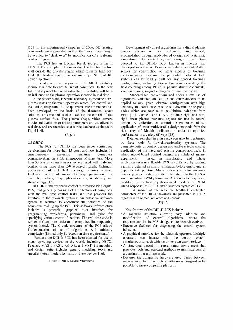
[13]. In the experimental campaign of 2006, NB heating commands were generated so that the two surfaces might be avoided to "clash over" by modification of a real-time control program. The PCS has an function for device protection in JT-60U. For example, if the separatrix line touches the first wall outside the divertor region which tolerates high heat load, the heating control supervisor stops NB and RF power injection. In recent years, the analysis codes for MHD instability require less time to execute in fast computers. In the near future, it is probable that an estimate of instability will have an influence on the plasma operation scenario in real time. In the power plant, it would necessary to monitor core-plasma states on the main operation screen. For control and evaluation, the plasma full shape reconstruction method has been developed on the basis of the theoretical exact solution. This method is also used for the control of the plasma surface flux. The plasma shape, video camera movie and evolution of related parameters are visualized in real time, and are recorded as a movie database as shown in Fig. 4 [14].
(Fig.4)
3.3 DIII-D The PCS for DIII-D has been under continuous development for more than 15 years and now includes 19 simultaneously executing real-time computers communicating on a Gb interprocess Myrinet bus. More than 50 plasma characteristics are regulated with real-time control using more than 550 acquired signals. Optimum performance of a DIII-D discharge requires accurate feedback control of many discharge parameters, for example, discharge shape, plasma current, line density, and stored energy [15]. In DIII-D this feedback control is provided by a digital PCS, that generally consists of a collection of computers with the real time control tasks and that provides the interface to the tokamak systems. An extensive software system is required to coordinate the activities of the computers making up the PCS. This software infrastructure includes a powerful graphical user interface for programming waveforms, parameters, and gains for specifying various control functions. The real-time code is written in C and runs under an interrupt-free linux operating system kernel. The C-code structure of the PCS allows implementation of control algorithms with arbitrary complexity (limited only by execution time requirements). Because the DIII-D PCS has been adapted for use at many operating devices in the world, including NSTX, Pegasus, MAST, EAST, KSTAR, and MST, the modeling and design suite includes generic modeling tools and specific system models for most of these devices [16].
(Table 4. DIII-D Device Parameters)
Development of control algorithms for a digital plasma control system is most efficiently and reliably accomplished through model-based design and systematic simulation. The control system design infrastructure coupled to the DIII-D PCS, known as TokSys and developed over the last 15 years, includes a suite of Matlab scripts for construction of linear models of tokamak electromagnetic systems. In particular, poloidal field systems can be readily built for any general tokamak configuration, including Green functions describing the field coupling among PF coils, passive structure elements, vacuum vessels, magnetic diagnostics, and the plasma. Standardized conventions and codes allow use of algorithms validated on DIII-D and other devices to be applied to any given tokamak configuration with high accuracy and confidence. A suite of axisymmetric response codes which are coupled to equilibrium solutions from EFIT [17], Corsica, and DINA, produce rigid and non-rigid linear plasma response objects for use in control design. A collection of control design codes allows application of linear multivariable design methods from the rich array of Matlab toolboxes in order to optimize performance in a variety of ways [18]. Detailed searches in gain space can also be performed by these tools for low-dimensionality systems. The complete suite of control design and analysis tools enables application of the integrated plasma control approach, in which model-based control designs are validated against experiment, tested in simulation, and whose implementation in a flexible PCS is confirmed by running against a detailed dynamic simulation before employing in experimental operation. Many non-axisymmetric tokamak control physics models are also integrated into the TokSys suite, including RWM plasma and 3D conductor responses, modified Rutherford equation-based models of NTM island responses to ECCD, and disruption dynamics [19]. A subset of the real-time feedback controlled parameters of the DIII-D tokamak are presented in Fig. 5 together with related actuators and sensors.
(Fig. 5)
Key features of the DIII-D PCS include:• A modular structure allowing easy addition and
modification of control algorithms, where the requirements for the PCS change as the research evolves.
• Extensive facilities for diagnosing the control system behavior.
• A graphical interface for the tokamak operator. Multiple operators can interact with the control system simultaneously, each with his or her own user interface.
• A structured algorithm programming environment that provides tools and standard methods to minimize control algorithm programming work.
• Because the computing hardware used varies between experiments, the infrastructure software is designed to be portable to most computing platforms.

• Real-time equilibrium reconstruction integrated with the "isoflux" boundary control scheme. Both PID and multivariable state space-based controllers are accommodated in the feedback scheme.
• Advanced algorithms for NTM detection, alignment, tracking, and suppression.
• Nonlinear coil current limit avoidance integrated with state space control.
• Fault detection and response architecture allowing switch to alternate operating modes depending on sequence of fault occurrence.
Key features of the modeling/simulation infrastructure for the DIII-D PCS include:• Full integration with the commercial Matlab/Simulink
environment.• Extensive validation of electromagnetic calculations and
plasma response functions against several operating tokamaks.
• Tools for electromagnetic field calculations, construction of tokamak electromagnetic couplings, model-based control design tools, linear and nonlinear simulation tools, validation tools (for comparison of model predictions with experimental data in operating devices).
• Special dynamic simulations which can be coupled to the PCS in order to test control algorithm function and confirm correct implementations.
• Ability to run the PCS against previous discharge data in addition to dynamic simulations in order to test control algorithms.
3.4 ASDEX-Upgrade The current PCS for ASDEX-Upgrade started routine operation in 2005. The device parameters are shown in Table 5. Flexible operation scenarios guarded by intelligent and reliable device protection should be explored as the main target.
(Table 5. ASDEX-Upgrade Device Parameters)
Table 6 shows the list of the real-time feedback controlled parameters with their attributes, and the system configuration of the PCS for ASDEX-Upgrade is shown in Fig 6.
(Table 6)(Fig. 6)
The PCS is deployed on a cluster of eight computers with VxWorks 6.3 and Linux operating systems. Real-time data is exchanged via a Bit3 reflective shared memory and a gigabit LAN.
Basic design features are separation of algorithmic code into application modules and system services like data transport, event logging and parameter configuration into an infrastructure framework. Timestamped discharge and
plant state variables are made available to all applications by automatic routing [20, 21]. The scheme has built-in dry-run capability and support for plasma simulators. This can be accomplished by substituting data acquisition applications by suitable data generator applications. The notable features of the PCS are as follows: • Parallel distributed computing with transparent data
sharing.• Data-driven process synchronization• Configurable (Data-driven) feedback control and
monitoring[22].• Dynamic switching between operation modes• Intelligent rule-based discharge flow scheduling
dependent on plant state and operation schedule. The basic philosophies for the design of protection systems are robustness and high-reliability through low complexity. The following specific methods have been developed:• Hardwired closed-loop generic alarm system to request
an immediate pulse termination (pulse stop) or controlled soft stop by opening the loop(s). (e.g. Stress of PF-coil suspension, plasma current, density, hot-spot on the wall, disruption mitigation with killer gas injection, power supply converter fails)
• High-level monitoring and protection algorithms are provided by the control system software: machine limits, operation window limits, programmable range limits for coil currents and equilibrium variables, disruption probability, radiation peaking, self-checking of control system. Threshold violations trigger a soft stop or pulse stop depending on the severity.
The goal is to develop and provide mechanisms for safe operation to protect both the device and the environment (people). As the existing tokamaks and also ITER are devices devoted to exploration and development, the control system must adapt quickly to new requirements. On the other hand, ITER will probably be more restrictively operated under the control of nuclear licensing. Cautious discharge planning, consistency checks and simulations prior to execution and intelligent fault handling will be much more important than they are today. A commercial power plant would rely on routine operation based on proven but not necessarily cutting-edge hardware technology, and a small set of well-tested control functions with more or less fixed parameters. In addition, such a plant would be optimized for long-term availability using redundant hard- and software components.
3.5 Tore Supra Tore Supra is the only superconducting tokamak among the selected devices in this paper. Its device parameters are shown in Table 7 [23]. There has been a continuous upgrade process of the Real Time Plasma Control and Data

Acquisition System (PCS/DAS) in Tore Supra. Nevertheless, it’s worth noticing the following key dates in the recent years; in 1995, the redesign of PCS/DAS with VME hardware and Power PC processors monitored by a real time Unix OS (LynxOSTM); in 2001, the major upgrades of PCS/DAS towards real time control of long pulse operation with continuous data acquisition, continuous data access, and real-time processing through a shared memory network (SCRAMNet® boards from SYSTRAN Corporation) [24, 25].
(Table 7. Tore Supra Device Parameters)
Table 8 shows the list of the real-time feedback controlled parameters with their attributes, and the system configuration of the PCS for Tore Supra is shown in Fig 7. [24, 26, 27].
(Table 8)(Fig. 7)
On the physics and operation scenario control front, the four major achievements are: (i) feedback control of the lower hybrid deposition profile from Hard X ray measurements [28]; (ii) RF heating optimization and Plasma Facing Component protection using InfraRed thermography diagnostics in real-time [29]; (iii) implementation of new real-time feedback controls for long duration discharge management [27, 30]; (iv) integrated scenario control development [31, 32]. For applying the PCS to a power plant, the present system has been designed to meet the requirements of a long pulse real-time controlled experimental facility. Additional requirements, especially with respect to reliability and safety, would have to be taken into account for an application to a power plant. The notable features are the integrated PCS and DAS, real-time processing through a shared memory network, continuous data acquisition, and continuous data access [25]. The latter two concepts might be applicable to a steady state power plant. For device protection, a central controller of PCS can forbid the operation of the heating power systems and gas fuelling systems if the plasma load is not within a acceptable operation window (with respect to minimum / maximum density, minimum plasma current, ripple losses limitations, etc.)
4. What is relevant to ITER and power plants?
We have surveyed the PCSs for JET, JT-60U, DIII-D, ASDEX-Upgrade, and Tore Supra in detail, mainly focusing on control functions. Here we discuss the PCS from the two viewpoints: as a plasma control tool and as an operation supervisor. First of all, the evolution of the PCS role shall be considered. On the basis of our experience since the invention of the
tokamak, one of the major objectives is to find the response functions between various actuators such as coils (electromagnetic field), heating, fueling, etc., and plasma performance such as density, temperature, confinement time, and Q (energy multiplication factor). As shown in Fig. 8 (a), the relations between a plasma and other components are clear. In the early stages of tokamak experiments, the operation physicist changed actuator signals pulse by pulse, and evaluated the resulting data. In this process, the operator performed a kind of feedback control, and there was almost no PCS since the plasma was dynamically stable. Soon analog circuits were employed to maintain the plasma position inside the vacuum vessel, using the vertical field coil power supply, and a small number of pick-up coil sensors. At this stage, it may be considered that the PCS was born. The first operational feedback loops for position control were applied to the tokamak in early 1970s. As computer technology advanced rapidly, fast digital processors were applied to the PCS. Energetic heating systems such as NBI and RF systems, and fast gas feed systems were also rapidly developed, and installed on tokamaks. In the 1980s, the PCS was developed corresponding to the experimental objectives for large and medium-size tokamaks. The role of PCS was to provide feedback control functions as a plasma control tool. The operator still designed the operational scenario pulse by pulse. When the pulse duration was extended to more than several seconds, the concept of "operation scenario" started being discussed. In the 1990’s and early 2000’s, as a result of a great deal of testing of new concepts in the world tokamaks, knowledge on plasma control continued to be accumulated. The operators started to set the scenarios into the PCS as a discharge condition. At this point in time, the PCS is no longer expected to be only a plasma control tool, but has become an operation supervisor. We can now ask what is relevant to ITER and to fusion power plants in the PCS which are currently used on the existing tokamaks. The following remarks could be made as the answers:
(i) Since the PCS configurations in these tokamaks have been optimized as physical experimental facilities, they are naturally relevant to ITER.
(ii) If we improve the current systems from the presently weak viewpoints of reliability, robustness, redundancy, they would be relevant to a fusion power plant, but safety would still have to be addressed
(iii) The real-time feedback control methods and algorithms are generally applicable to ITER and fusion power plants. The same principal control parameters have to be controlled, namely: plasma current, position and shape, current profiles, density, temperature, neutron yield, edge density, etc.
(iv) Since computer performance has already attained the

required level for all the primary feedback control application, commercial off-the-shelf technology could probably be used for PCS.
(v) Communication technology such as Ethernet network, shared memory concept, etc., has also reached high levels applicable to ITER and a power plant.
(vi) Advanced approaches like estimation of plasma instability growth rates and predictive control would need far higher computing power, but this is becoming available.
As a consequence of the development history, the PCS for ITER could have a set of basic operation scenario tools based on accumulated, established knowledge as an operation supervisor, as shown in Fig. 8 (b). Examples of integrated control which could reside in such a package include: breakdown optimization procedures, H-mode breakeven, Elmy H-mode breakeven, RS breakeven, instabilities predictor and avoidance, neutron yield control, normal shut down procedure, emergency shut down, cleaning of first wall, commissioning, etc. Simulator for tokamak system is very effective, and this technology is relevant to ITER. In a power plant, the PCS would provide a much higher level of operation scenario, such as: start, terminate, generation power, Li burn-up, commissioning.
5. ITER and its present status
The international collaborative project ITER is expected to be the only tokamak experimental reactor linking us directly to a demonstration fusion power plant. From the device parameters as shown in Table 9, this device is clearly a huge integrated plant that we have never experienced in the tokamak history. At the same time, however, this device is required to demonstrate a variety of advanced tokamak operation scenarios with a DT plasma. The PCS must have a sufficiently flexible structure for the efficient exploitation of all known scenarios and allow extension to unknown scenarios to be developed during the 9 remaining years of construction.
(Table 9. ITER Device Parameters)
The ITER Plant Description Document (PDD) [33] calls for a flexible plasma control to cover the three main research phases (H2, D2, D2&T2) for inductive and non-inductive current drive. It also calls for key safety systems, interlocks and protection of investment and for operations defined by limits set by the ITER program, which will naturally evolve. The major challenges facing the design of the ITER CODAC, of which the pulse control system is a part, are listed as follows:
(a) A nuclear facility
(b) Procurement of the major technical systems “in- kind”(c) Reliability and availability(d) International exploitation(e) Long timescale to construct(f) Continuous operation rather than pulse-based(g) Complexity
It is significant that plasma control is not on this list. It is considered that the current understanding of plasma control is adequate to ensure basic operation, and that the construction of a plasma control system based on an extrapolation of our existing concepts is the correct way to move forwards. Parameters to control in ITER are assumed almost the same subset as those in the existing tokamaks. We briefly comment on the 7 challenges in turn.(a) Operation of a nuclear facility demands an approach to safety which is not explored in our present devices. However, there are no concepts which are not adequately developed in the fission field for use on ITER. The ITER CODAC approach envisages a total separation between Safety, Investment Protection and CODAC.(b) “In-kind” procurement brings a challenge of integration and standardization, but no challenge to Plasma Control, since the whole of CODAC is procured centrally.(c) Reliability and availability have been mentioned, and require attention in the CODAC Pulse Control System. A thin software layer will provide a last resort validation of commands to actuators. All networks linked to the operation of an ITER pulse are redundant, since the lost investment of a single prematurely aborted pulse is very high. Industrial standards are adequate and applicable.(d) International exploitation does not concern the Pulse Control System, except the requirement to design pulses collaboratively.(e) Long timescale to construct brings no specific Pulse Control challenge.(f) Continuous operation has a technical implication of storing and making available all the experimental data during a pulse. However, it also underlines the vital requirements of intelligent optimization of an ongoing pulse. This point has been raised repetitively in this paper and is a major challenge to ITER.(g) Complexity is not a new challenge to the Pulse Control System, since the total number of actuators and control parameters is not so different from present tokamaks (fewer PF coils, fewer heating beams, fewer antennae etc). The number of sensors is likely to be similar or smaller than our present experiments.
The major challenge recognized by ITER, and by the control experts on existing tokamaks is therefore one of controlling the pulse in the “optimization and strategy” sense. CODAC foresees a strategy of “segments” designed to perform specific functions or experiments, which are joined together to produce a “pulse”. This creates a slightly

different approach to scenario design. This approach also allows international generation of segments and international generation of pulses, a primary project requirement. It allows us to introduce a new concept of an “Operation Request Gatekeeper”. This allows a potentially damaging pulse design to be identified and not allowed into the “Plant Operation Zone”. This zone is the zone which manages the local Cadarache operation of ITER and is responsible to the regulator for the safe operation of the whole plant. Concerning algorithms, there is no identified ITER requirement to develop a new method or algorithm. However, there is clearly much work to be done on our existing tokamaks to generate robust techniques for plasma profile control.
ITER will be a large, long-lived machine. The staff with expert knowledge will move on, and the CODAC equipment will become obsolete, as was the case on JET. CODAC must therefore provide systems which are (i) configurable, (ii) extensible, (iii) traceable, and (iv) reproducible. For many types of operations (both plasma control and other machine operations), it will use automated schedules with “plug-in” components running in sequences, communicating in real-time. e.g. for moving data to the remote sites, for scientific and engineering data analysis, for plasma control, for many of the plant operations. The plant systems will interpret these general operations sequences, driving their PLCs and PCs accordingly. The “plug-ins” could be simple file manipulations or complex physics/engineering codes. Thus CODAC will consist of user-workstations to edit and launch schedules, “engines” to execute the “plugins”, and communications networks for both supervisory control & status and for process input & output. The CODAC has the several layers in its hardware configuration as shown in Fig.9 [34].
(Fig.9)
6. Concluding Remarks
We have reviewed 2 large-, and 3 medium-size tokamaks, namely JET, JT-60U, DIII-D, ASDEX-Upgrade, and Tore Supra, summarizing their major features. The ongoing conceptual design of ITER CODAC has also been summarized. On the basis of the above review, we can envisage a future PCS for ITER and a fusion power plant as both operation supervisor as well as a plasma control tool. It is concluded that the accumulated knowledge of feedback control techniques and operation scenarios for maintaining a high performance plasma is not only relevant to ITER and fusion power plants, but will inevitably form the backbone of the optimal exploitation of both of them. The common PCS features among the selected tokamaks optimized as physical experimental facilities are clearly relevant to ITER. If we improve the current PCS
concepts from the viewpoints of reliability, robustness and redundancy, they would still be relevant to a fusion power plant.
Acknowledgements
The authors would like to express their gratitude to the colleagues in the field of magnetic fusion research and engineering in the world. This research has been partly performed under the European Fusion Development Agreement and was partly funded by the UKAEA, the UK Engineering and Physical Sciences Research Council and by the European Communities under contract of association between EURATOM and UKAEA. The views and opinions expressed herein do not necessarily reflect those of the European Commission.
References [1] M.L.Watkins et al., Overview of JET Results, Fusion Energy
2006 (Proc. 21st Int. Conf. Chengdu, 2006) IAEA, (2006)[2] A Murari et al, Development of real-time diagnostics and
feedback algorithms for JET in view of the next step, Plasma Phys. Control. Fusion 47 (2005) 395-407
[3] R. Felton et al., Real-time measurement and control at JET experiment control, Fus. Eng. Des. 74 (2005) 561-566
[4] F. Sartori et al., The system architecture of the new JET shape controller, Fus. Eng. Des. 74 (2005) 587-591
[5] K. Kurihara et al., Plasma real-time control system for advanced tokamak operation scenarios in JT-60, IEEE Trans. Nucl. Sci., 47 (2000), 205-209.
[6] A. Isayama et al., Stabilization of neoclassical tearing modes by electron cyclotron current drive in JT-60U, Nucl. Fusion 47 (2007) 773–782
[7] K. Shinohara et al., Ferritic insertion for reduction of toroidal magnetic field ripple on JT-60U, Nucl.Fusion 47 (2007) 997–1004
[8] K. Kurihara et al., "Status and prospect of JT-60 plasma control and diagnostic data processing systems for advanced operation scenarios, Fusion Eng. Des. 81, (2006), 1729-1734
[9] T. Suzuki et al., Off-axis current drive and real-time control of current profile in JT-60U, Nucl. Fusion 48 (2008) 045002
[10] K. Kurihara, A new shape reproduction method based on the Cauchy-condition surface for real-time tokamak reactor control, Fusion Eng. Des., 51-52, (2000), 1049-1057.
[11] G. Matsunaga et al., Effect of plasma-wall separation on the stability of resistive wall modes in the JT-60U tokamak, Plasma Phys. Control. Fusion 49 (2007) 95–103
[12] M. Takechi et al., Identification of a low plasma-rotation threshold for stabilization of the resistive-wall mode, Physical Review Letters 98 (2007), 055002
[13] M. Yoshida et al., Fast measurement of ion temperature using filter charge exchange recombination spectroscopy system towards real-time plasma control in JT-60U, Trans. Fusion Sci. Tech. 51 (2007) 301-303.
[14] M. Sueoka et al., The plasma movie database system for JT-60, Fusion Eng. Des. 82, (2007), 1008-1014
[15] D. A. Humphreys, et al., High performance integrated plasma control in DIII-D, Fusion Eng. Des. 74 (2005), 665
[16] J. R. Ferron et al., A flexible software architecture for tokamak discharge control systems, to be published in a Journal on Fusion

[17] J. R. Ferron et al., Real time equilibrium reconstruction for tokamak discharge control, Nucl. Fusion 38 (1998), 1055
[18] D. A. Humphreys, et al., Development of ITER-relevant plasma control solutions at DIII-D, to be published in NF.
[19] J. A. Leuer et al., DIII-D integrated plasma control tools applied to next generation tokamaks, Fusion Eng. Des. 74 (2005), 645
[20] W. Treutterer et al., The new ASDEX Upgrade real-time Control and data acquisition system, Fusion Eng. Des. 66-68 (2003), 755-760
[21] G.Raupp et al, Control process structure of ASDEX Upgrade's new control and data acquisition system, Fusion Eng. Des. 74 (2005), 697
[22] W. Treutterer et al., Plasma feedback controller reorganisation for ASDEX Upgrade's new discharge control and data acquisition system, Fusion Eng. Des. 82 (2005), 300-303
[23] P. Moreau et al., Towards control of steady state plasma on Tore Supra, Proc 45th IEEE Conf on Decision and Control (2006).
[24] :F. Leroux et al., Real time data acquisition system for control and continuous acquisition in Tore Supra, Proc 2003 IEEE Real Time Conference (2003).
[25] B.Guillerminet et al., Tore Supra continuous acquisition system, Fusion Eng. Des. 60 (2002) .427-434
[26]: D.Moulin et al., Tore Supra : the real time plasma control system, in Proc the 20th Symp On Fusion Tech I (1998).
[27] F. Saint-Laurent et al., Real time control of long duration plasma discharges in Tore Supra, Proc 9th Int. Conf. on Accelerator and Large Experimental Physics Control Systems (2003)
[28] O. Barana et al., Feedback control of the lower hybrid power deposition profile on Tore Supra, Plasma Phys. Control. Fusion 49 (2007) 947-967.
[29] :P. Moreau et al., RF heating optimization on Tore Supra using feedback control of infrared measurements, accepted for publication in Fusion Engineering and Design.
[30] : D. van Houtte et al., Real time control of fully non-inductive operation in Tore Supra leading to 6 min, 1 GJ plasma discharges, Fusion Eng. Des, 74 (2005). 651-658
[31] D. Mazon et al., New real-time profile controls for steady state operation in Tore Supra, Proc 33rd European Physical Society Conference on Plasma Physics (2006)
[32]:E. Witrant et al., A control-oriented model of the current profile in tokamak plasma, Plasma Phys. Control. Fusion 49 (2007) 1075-1105.
[33] ITER Plant Description Document, IAEA (1997)[34] J. B. Lister et al., ITER CODAC Concept Design Documentation
2006, (2007)

Fig. 1 Sophistication Process of Plasma Control

Fig. 2. The Configuration of the PCS and Measurement System in JET.

Fig. 3. The Configuration of the PCS and Measurement System in JT-60U.

Fig. 4. The plasma real time movie system and data storage in JT-60U

Fig. 5. Real-time FB controlled parameters with actuators and sensors in DIII-D.

Fig.6. The Configuration of the PCS in ASDEX-Upgrade.

Fig.7. The Configuration of the PCS in Tore Supra.

(a) In the early stages of tokamak experiments, the operation physicist changed actuator signals pulse by pulse.
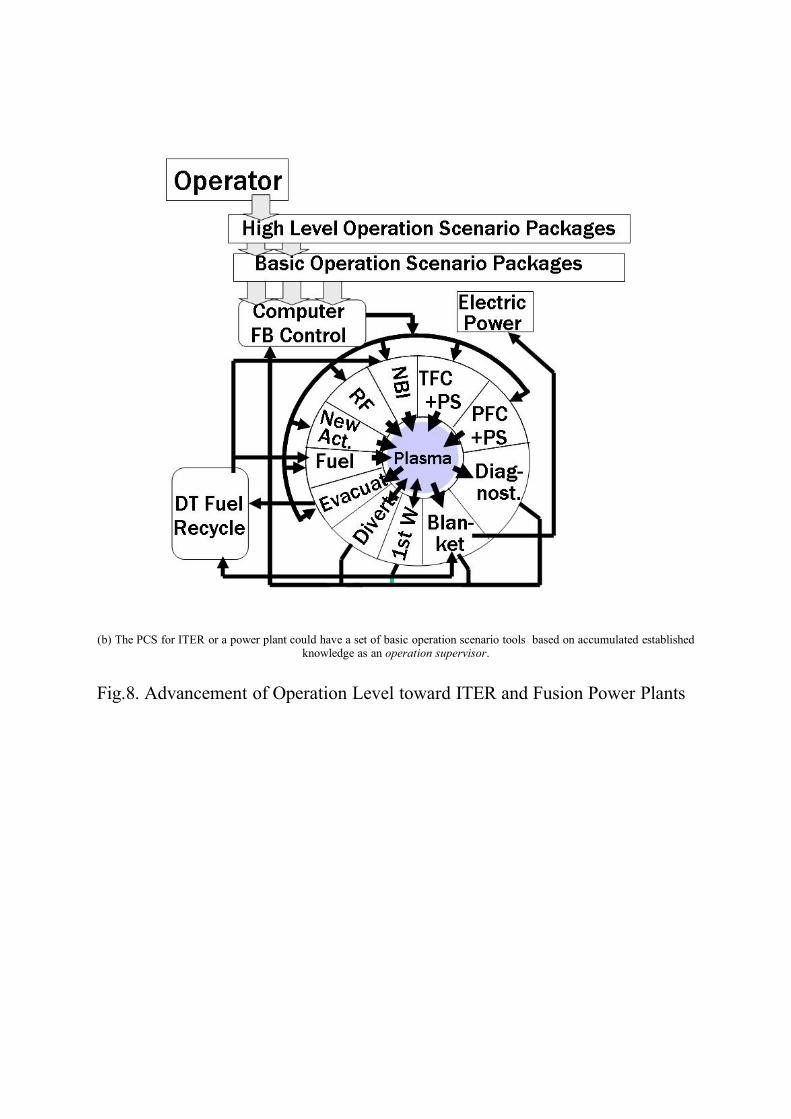
(b) The PCS for ITER or a power plant could have a set of basic operation scenario tools based on accumulated established knowledge as an operation supervisor.
Fig.8. Advancement of Operation Level toward ITER and Fusion Power Plants

Fig.9. CODAC Configuration in ITER.

Table 1. JET Device Parameters------------------------------------------------------------------------------
Ip < 5MA, Major/Minor Radius/Elongation 3.0 m/ 1.2 m/ 1.7Pulse Length 30 s ~ Btor < 3.45T Ti < 30keV ne ~ 1E20 m-3
Fuel/ Volume D (+T)/ ~80 m3 NB > 20 MW, RF > 4 to 8 MW Max total input power/energy ~ 32 MW/~ 320 MJ Typical heat length (Max) ~ 10 s (~ 20 s) Typical pulse power consumption 500 MW
------------------------------------------------------------------------------
Table 2. JT-60U Device Parameters----------------------------------------------------------------------------------
Item Normal Pulse Long Pulse----------------------------------------------------------------------------------
Ip < 5MA, 1.4 MA/0.7 MAMajor/Minor Radius/Elongation 3.3m/ 1.0 m/ < 1.7Pulse Length 15 s 30 s /65 s Btor 4 T, 8 s 3.3 T/2.7 T Max total input energy 200 MJ 350 MJFuel/ Volume D / ~100 m3 P-NBI Perp Inj. 7 units 18 MW, 10 s 8 MW, 20 s Tang Inj 4 units 12 MW, 10 s 8 MW, 30 sN-NBI ~5 MW, ~1 s 3.2 MW, 21 s ECH 2.8 MW, 3.6 s 0.5 MW, 30 s LHRH 3.5 MW, 10 s 1.1 MW, 20 s
----------------------------------------------------------------------------------

Table 3. Real-time FB controlled parameters and method with actuators and sensors in JT-60U
Controlled parameter Associated measurements
Actuator control cycle
Period Control Method
Plasma position and shape including divertor separatrix line
Magnetic sensors, andCauchy Cond. Surface Method
PF coils power supply 0.25 ms (Vertical)0.5 ms(Others)
throughout pulse
PD
Plasma current Rogowski Coil orCauchy Cond. Surface Method
PF coils power supply 0.5 ms throughout pulse
PD
Magnetic flux at plasma surface
Magnetic sensors OH coils power supply
0.5 ms throughout pulse
P
Plasma current profile
Magnetic sensors, MSE
LH power, (N-NB) 10 ms throughout pulse
PD
Plasma line integrated electron density
Infrared interferometer, CO2 Laser
Gas piezo valves, Gas jet, Pellets
10 ms throughout pulse
PD
Plasma Ion Temperature
CXRS(Charge eXchange Recombination Spectroscopy)
P-NBI 10 ms throughout pulse
PD
Radiated power from core/divertor plasma
bolometers Gas injection systems 10 ms throughout pulse
PD
Neutron Yield U235/238-Fission Chamber
P-NBI 10 ms throughout pulse
PD
Stored Energy Diamagnetic loop sensors
P-NBI 10 ms throughout pulse
PD
Plasma Rotation Velocity Profile
CXRS P/N-NBI 10 ms throughout pulse
PD
Electron Temperature, and Its Gradient (at a fixed radius)
ECE diagnostic P-NBI 10 ms throughout pulse
PD l
Table 4. DIII-D Device Parameters----------------------------------------------------------------------------------
Ip < 3 MA, Major/Minor Radius/ Elongation 1.70 m/ 0.6 m/ < 2.5Pulse Length < 8 sBtor 2.1 TMax total input power/energy 28 MW/100 MJFuel/ Volume D / ~ 25 m3 P-NBI Perp Inj 10 MW, 5 s Tang Inj 10 MW, 5 sECH/ECCD 6 MW, 2 s
----------------------------------------------------------------------------------

Table 5. ASDEX-U Device Parameters----------------------------------------------------------------------------------
Ip < 1.6 MA, Major/Minor Radius/Elongation 1.65 m/0.5 m/1.6Pulse Length 10 sBtor 3.9 TFuel/Volume D/ ~13 m3 P-NBI 20 MWICRF 6 MWECRH 2 MW
----------------------------------------------------------------------------------
Table 6. Real-time FB controlled parameters and method with actuators and sensors in ASDEX-U
controlled parameter
Associated measurements
actuator system control cycle
period method
current magnetic sensors central solenoid 1.5 ms throughout pulse PI
position magnetic sensors fast control coils 1.5 ms throughout pulse matrix PI
shape magnetic sensors PF coils 1.5 ms diverted phase matrix PI
density DCN, manometerBremsstrahlung
gas inlet system,pellets
1.5 ms throughout pulse PI
radiation Bolometry gas inlet system 1.5 ms programmable PI
confinement magnetic sensors NBI 1.5 ms programmable PI
MHD mode ECE, Mirnov, magnetic sensors, MSE
ECRH with steerable mirrors
5 ms programmable tbd
MHD mode (in italics) control is a project in the startup phase and not yet fully implemented.

Table 7. Tore Supra Device Parameters------------------------------------------------------------------------------------
Ip < 1.5 MA, Major/Minor Radius 2.4 m/ 0.72 mPulse Length ~ 1000 s - 378 s
achievedBtor < 4.2 TFuel/ Volume D / ~25 m3
Max total input power/energy ~ 32 MW/~ 320 MJPlasma heating systems (IC, LH, EC) 20 MW (plant)
- 11MW achieved----------------------------------------------------------------------------------
Table 8. Real-time FB controlled parameters and method with actuators and sensors in Tore Supra
Controlled parameter Associated measurements
Actuator control cycle
Period Control Method
Plasma position and shape
Magnetic sensors PF coils power supply 2.0 ms throughout pulse
PID
Plasma current (or edge safety factor)
Magnetic sensors PF coils power supply and/or LH power transmitter
2.0 ms throughout pulse
PID
CS Transformer Magnetic flux (and associated plasma loop Voltage)
Magnetic sensors PF coils power supply 2.0 ms Flat-top PID
Plasma line integrated electron density (or Greenwald fraction)
Infrared interferometer
Gas piezo valves, Supersonic Beam Molecular Injector, Pellets
2.0 ms throughout pulse
PID
Radiated power fraction
bolometers Gas injection systems (impurities)
2.0 ms throughout pulse
Limit or cut the gas injection above a given value of radiated power
Heating systems power (IC, LH)
Infrared thermography diagnostic
Heating systems power transmitter
20.0 ms throughout pulse
P like control
Current profile peaking (LHCD profile maximum and/or width at half maximum, internal inductance, central safety factor)
Hard X ray measurements, magnetic sensors
LHCD system power and main refractive index (phase shift between LH waveguides)
16.0 ms throughout pulse
PID control
Normalized electron temperature gradient (at given radius)
ECE diagnostic LHCD system power and main refractive index (phase shift between LH waveguides)
16.0 ms throughout pulse
PID control
Table 9. ITER Device Parameters------------------------------------------------------------------------------
Ip < 17 MA, Major/Minor Radius/elongation 6.2 m/ 2.0 m/1.85

Pulse Length ~ up to 12000 s Btor < 5.3 TMax total plasma energy 357MJFuel/ Volume H, D, D+T / ~880 m3
Max total input power/energy ~ 73 MW/~ 320 MJPlasma heating systems 73 MW (plant) ------------------------------------------------------------------------------