planning scheme policy - neighbourhood design · planning scheme policy neighbourhood design. ......
TRANSCRIPT

Planning Scheme PolicyNeighbourhood Design

Table of Contents Amendment ............................................................................................................................................................ 2
1 Introduction .................................................................................................................................................... 2
2 Purpose ........................................................................................................................................................... 3
3 Application ..................................................................................................................................................... 3
4 Site Analysis .................................................................................................................................................. 4
4.1 Items to include in a site analysis ........................................................................................................... 5
5 Neighbourhood Structure ............................................................................................................................... 6
5.1 Grid Structures ....................................................................................................................................... 7
5.2 Grid Dimensions .................................................................................................................................. 10
5.3 Framework Roads ................................................................................................................................ 11
5.4 Orientation of streets ............................................................................................................................ 12
5.5 Interface with limited access streets ..................................................................................................... 15
5.6 Laneways for residential development ................................................................................................. 17
5.7 Intersection types and spacing ............................................................................................................. 18
5.8 Connecting to the existing and future street network ........................................................................... 20
5.9 Transitions between precincts and zones ............................................................................................. 22
5.10 Open Spaces ......................................................................................................................................... 23
5.11 Stormwater ........................................................................................................................................... 26
5.12 Green infrastructure network (GIN) ..................................................................................................... 27
5.13 Centres ................................................................................................................................................. 30
6 Refining the Layout...................................................................................................................................... 32
7 Density ......................................................................................................................................................... 34
7.1 How to measure density: ...................................................................................................................... 36
7.2 Net residential density .......................................................................................................................... 37
7.3 Residential Diversity ............................................................................................................................ 39
8 Putting Density and Diversity into practice during Reconfiguring a Lot ..................................................... 41
8.1 Suburban Neighbourhood Precinct ...................................................................................................... 41
8.2 Next Generation Neighbourhood Precinct ........................................................................................... 42
8.3 Urban Neighbourhood Precinct ............................................................................................................ 43
9. Enterprise and Employment Areas ............................................................................................................... 44
9.1 Location ............................................................................................................................................... 45
9.2 Structure ............................................................................................................................................... 46
9.3 Movement ............................................................................................................................................ 47
9.4 Stormwater ........................................................................................................................................... 48
9.5 Open Space and Local Facilities .......................................................................................................... 49
9.6 Retention of high value Vegetation ...................................................................................................... 50

9.7 Transitions to other zones. ................................................................................................................... 51
10 Neighbourhood development plans .......................................................................................................... 52
10.1 Introduction .......................................................................................................................................... 52
10.2 NDP areas ............................................................................................................................................ 52
10.3 NDP preparation process...................................................................................................................... 54
10.4 Planning elements to consider when preparing a NDP ........................................................................ 56
End Notes ............................................................................................................................................................. 60
Page 1 of 61

Adoption Moreton Bay Regional Council adopted this planning scheme policy on 24 November 2015.
Commencement This planning scheme policy will take effect from 1 February 2016.
Amendment Alignment amendment 1 2017
• Adopted by Moreton Bay Regional Council on 27 June 2017 • Took effect from 3 July 2017
1 Introduction This policy supports the Moreton Bay Regional Council Planning Scheme and has been made by Council in accordance with Chapter 2, Part 3, Division 2 of the Planning Act 2016. The MBRC Planning Scheme Strategic Framework which is intended to guide development within the MBRC area emphasises the importance of place making and urban design to create quality human habitats. This is particularly important as the planning scheme seeks to accommodate more people and jobs within existing and new urban areas, protect green networks, avoid flood hazards, provide for movement within and between places, and to improve the integration and coordination of land use planning and infrastructure delivery. All new development will be, where possible, planned, designed and delivered, to facilitate the creation of new neighbourhoods and contribute to the enhancement of existing neighbourhoods. Neighbourhood layout and design should respect and respond to local conditions including the local market, physical features, cultural heritage significance, views and vistas and connections to existing facilities and movement networks. This planning scheme policy sets out the process and content required for a Neighbourhood Development Plan (NDP) and provides more general guidance for neighbourhood design in areas not requiring the preparation of a NDP.
A NDP is intended to: • detail all aspects of future development of a neighbourhood including the local street networks, land
uses (through the allocation of sub-precincts), density, built form, open spaces, school site boundaries, sewer and water and other infrastructure.;
• show how the various sub-precincts, or the desired places within the sub-precincts are designed to form part of an integrated overall urban structure within the local plan area; and
• precede and guide development applications within a neighbourhood.
Page 2 of 61

2 Purpose The purpose of this policy is to:-
1. Provide a guide for the design of reconfiguring a lot applications which achieve the outcomes of the applicable parts of the planning scheme.
2. Provide guidance to the information required when submitting development applications.
3. Identify the key attributes of neighbourhood planning.
4. Provide guidance on the preparation of an NDP, where required by the planning scheme.
5. Provide a guide to the evaluation of NDP’s against sustainability, financial feasibility, marketability
criteria.
3 Application This policy applies to: a) All reconfiguring a lot applications proposing more than 1 additional lot. b) An area identified in the planning scheme as requiring preparation of a NDP preceding consideration of
a development application (Refer Section 9 – Neighbourhood Development Plans); and c) An area identified by resolution of Council from time to time as requiring preparation of a NDP
preceding consideration of a development application; d) Within an identified NDP area, all assessable development other than transitional and interim
development specified in the planning scheme; The boundaries of a NDP and the timing/sequencing of the preparation of a NDP are determined by Council (refer Appendix 1) which may be reviewed by Council from time to time having regard to:
• progress of development of the area; • infrastructure staging requirements • Emerging issues that may arise from time to time in the area • Existing or prosed major features such as ridgelines, waterways, environmental values, major roads,
logical neighbourhood boundaries and significant land uses
Applications for assessable development other than transitional and interim development in an area identified as requiring a NDP will not be supported until there is an approved NDP prepared in accordance with this policy. Nothing contained in this policy shall preclude Council and the Applicant from entering into an agreement in regard to the matters dealt with by this policy. Where a NDP has been prepared by Council and the proposed development application has been prepared in accordance with the plan prepared or caused to be prepared by Council then the requirements of this policy are deemed to be complied with.
Page 3 of 61

4 Site Analysis A comprehensive analysis of the site and its surroundings should be undertaken before the layout is designed. Each site is unique and will require its own unique approach to development. The site layout must be designed around the unique features of the site and its surroundings.
Figure 1: Example of a site analysis
The first stage is to map the significant features of the site. Some of the matters that will need to be considered are outlined below. Council may request an applicant to demonstrate that appropriate site analysis has been undertaken as part of the Reconfiguring a lot application.
Page 4 of 61
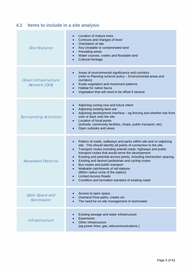
4.1 Items to include in a site analysis
Site Features
• Location of mature trees • Contours and changes of level • Orientation of site • Any Unstable or contaminated land • Prevailing winds • Water courses, creeks and floodable land • Cultural Heritage
Green Infrastructure Network (GIN)
• Areas of environmental significance and corridors
(refer to Planning scheme policy – Environmental areas and corridors)
• Koala vegetation and movement patterns • Habitat for native fauna • Vegetation that will need to be offset if cleared
Surrounding Activities
• Adjoining zoning now and future intent • Adjoining existing land use • Adjoining development interface – eg fencing and whether lots front
onto or back onto the site. • Location of focal points
(schools, community facilities, shops, public transport, etc) • Open outlooks and views
Movement Patterns
• Pattern of roads, walkways and parks within site and on adjoining
site. This should identify all points of connection to the site. • Transport routes including arterial roads, highways and public
transport routes that would serve the development. • Existing and potential access points, including intersection spacing. • Existing and desired pedestrian and cycling routes • Bus routes and public transport • Walkable catchments of rail stations
(800m radius circle of the station) • Limited Access Roads • Condition and formation standard of existing roads
Open Space and Stormwater
• Access to open space. • Overland Flow paths, creeks etc • The need for on site management of stormwater
Infrastructure
• Existing sewage and water infrastructure • Easements • Other infrastructure
(eg power lines, gas, telecommunications )
Page 5 of 61

5 Neighbourhood Structure The development must have an overarching structure that responds to its surroundings and the matters identified in the site plan. Developments must take advantage of the unique characteristics of their site and also be part of the structure of the town in which they are located. An outline plan shows how to respond to the site characteristics and guides the development of the urban structure. It demonstrates how the neighbourhood will function as part of a wider urban area.
The analysis should identify routes to and through the site along desire lines. The aim should be to connect the development in with its surroundings and to provide direct connections through the site, particularly to obvious nodes such as neighbourhood hubs or public transport.
Some of the matters to be considered are discussed below.
Figure 2: Outline plan responding to site analysis
Page 6 of 61

5.1 Grid Structures At this stage, a general conception of how the neighbourhood will work is needed. This will be refined through an iterative process of detailed design.
Cities were traditionally built on a grid structure with a walkable perimeter of around 400m-800m. For instance, much of Brisbane has a grid with dimensions of 100m x 200m. This structure ensures that it is possible to walk anywhere within the area relatively easily. More recently, with the widespread use of cul-de-sacs and other forms of poorly connected road pattern, street layouts have become less well connected and urban areas less walkable.
Desired Street Patterns
Rectilinear Grid
Modified Grid
A modified grid such as the one above can be used provided it has an overall structure that is
legible. The example above has a choice of direct routes running north-south and east-west
even though the orientation of grid cells is alternated.
Radiant Grid
Radiant grids are a way to respond to a focal point such as a station or town centre as they minimise travel distances from a central point.
Away from the focal point, the grid should transition to a rectalinear form.
Page 7 of 61

Undesired Street Patterns
Offset Grid
An offset grid such as the one above does not provide for east-west connections.
Fragmented Grid
A fragmented grid does not have the structure or legibility of a regular grid.
Loops and Lollipops
The occasional use of cul-de-sacs within a structured grid may be acceptable, but their
widespread use must be avoided.
Page 8 of 61

Dendritic
Highly disconnected car-dependent layouts are not acceptable
Fake Grid A fake grid has many of the attributes of a grid based layout but is not well connected. It does
not provide direct routes for travel and is not legible.
Page 9 of 61

5.2 Grid Dimensions
Maximum Block Sizes
Blocks will generally have a depth of between 50 and 70m. Block width will usually be around 2-3 times the depth of the block.
The maximum block dimension depends on the residential precinct in which the development is located, as follows:
General Residential Zone – Precinct Maximum walkable perimeter Coastal Communities & Suburban Neighbourhood 600 metres
Next Generation Neighbourhood 500 metres Urban Neighbourhood 400 metres
Block lengths greater than 200m should be used sparingly and a mid-block pedestrian link provided.
Figure 3: Walkable Perimeter
Responding to Land Use
The size of grid blocks will decrease with density and proximity to focal points, such as neighbourhood hubs, local centres or a transport stations.
Neighbourhood hubs should be designed around a grid structure with a perimeter of no more than 400m. If this cannot be met, then high quality pedestrian routes can be used within a standard sized grid pattern.
Page 10 of 61

5.3 Framework Roads A neighbourhood should be structured around a framework of higher order streets (eg local collectors) that act as the main transport corridors and provide for a variety of uses. The first stage of neighbourhood design is the location of these frame roads. The rest of the grid of local streets is then structured around them.
Figure 4: Grid built off framework roads.
It is important that these streets have a high level of amenity because they also function as liveable streets with direct residential frontage. They are also the best locations for parks and community facilities because of their higher profile.
Figure 5: Direct Access onto Local Collectors
Page 11 of 61

5.4 Orientation of streets For solar access
The best solar access will occur if streets are aligned approximately east-west and this should be the main orientation where possible. Streets that are aligned north-south should generally be the short side of the block. Other orientations should be minimised where possible but may be used to fit in with other design aims.
Figure 6: Solar Orientation
To complement a frame road or provide direct access to focal point
Sometimes a frame road will run through the development. These may be oriented to provide direct connections to neighbourhood hubs, public transport, parks or other focal points and buses may run down these roads. Because of this, these roads may not be oriented east west or north south and this may disrupt the grid.
If the grid is focussed on a station or neighbourhood hub, then this may also disrupt the orientation. The radiant grid in section 6.1 is an example of this.
Figure 7: Grid orientation to suit frame roads.
Short side of grid on north-south roads
Best solar orientation for
houses is on east – west streets
Blocks oriented to provide direct access to frame road
Frame Road
Page 12 of 61

To Manage the number of four way intersections
Four way intersections provide legibility and reduce traffic speeds. They are an important component of residential design.
However, it is sometimes appropriate to reduce the number of 4-way intersections, especially for busy roads. One way to do this is to rotate some parts of the grid through 90 degrees:
Figure 8: 4 way intersection management
To respond to topography
Topography is often the driver of street layouts and will always have some significance. Grid patterns may be distorted because of the constraints imposed by slopes. However, the need for a connected grid-based network remains, and grid blocks should still conform to a maximum walkable perimeter (as specified in the Reconfiguring a lot code).
Figure 9: Grid orientation to suit topography
Page 13 of 61

Limiting the use of Cul-de-sacs
Cul-de-sacs are not a preferred form of development but may be used on occasion as part of a layout that is mostly connected. The use of cul-de-sacs may include reaching an awkward corner of a site or to create a pedestrian only link onto a higher order road (avoiding a four way intersection).
Figure 10: Occasional use of Cul-de-sacs
Where cul-de-sacs are used to reach an awkward corner of the site, this should be limited in length and only be where other solutions are not viable.
Figure 10: Limited length of Cul-de-sacs
Page 14 of 61

5.5 Interface with limited access streets On local streets vehicle access will always be directly from the street. For collector roads, some judgement is needed. Where direct access is not possible, the following may be used. The best result may be a combination of solutions along the length of the street:
Figure 11: Slip Roads
Figure 12: Rear Lane Access
Rear lanes should be used sparingly and are not generally suitable for low density housing. The provision of on-street parking at the front of the house is important where laneways are used. The rear lane should be easily accessible from the front of the house (access should not involve convoluted journeys).
Figure 13: Access to an internal road
This option provides visual activation of the internal street but does not bring activity to the higher order road.
Page 15 of 61

Using an Accessway
Figure 14: Service Lanes/Accessways
Houses should not back onto collector roads. The use of transparent fencing is not appropriate mitigation next to busy streets as it compromises the privacy of residents and tends to be fenced over time.
Figure 15: Addressing the street
Page 16 of 61

5.6 Laneways for residential development In residential areas, laneways can be used in the following circumstances: • As a way to avoid front access on limited access roads • Where houses are opposite a local or district park
Laneways are not especially suitable for low density housing (principally due to cost).
Laneways should be straight and of limited length:
Figure 16: Laneway Design
Page 17 of 61
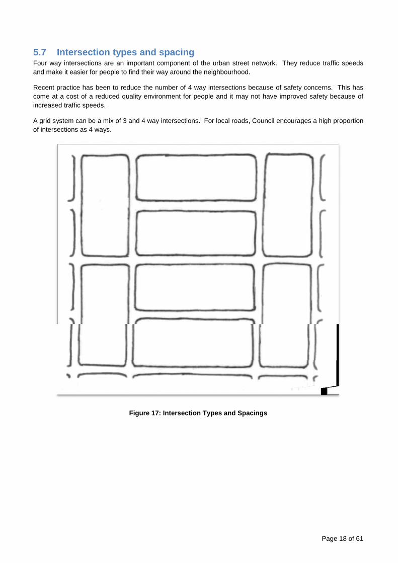
5.7 Intersection types and spacing Four way intersections are an important component of the urban street network. They reduce traffic speeds and make it easier for people to find their way around the neighbourhood.
Recent practice has been to reduce the number of 4 way intersections because of safety concerns. This has come at a cost of a reduced quality environment for people and it may not have improved safety because of increased traffic speeds.
A grid system can be a mix of 3 and 4 way intersections. For local roads, Council encourages a high proportion of intersections as 4 ways.
Figure 17: Intersection Types and Spacings
Page 18 of 61

Figure 18: Maintaining connectivity
Collector Roads The design of collector roads may be more complicated than other roads because of the need to take account of the different types of land use. A collector road is a multi-purpose street which must provide for place activities as well as movement activities. It needs to be a pleasant and attractive place for people. Place activities can include space for social activities such as seating areas and space for people to stop and linger; and amenity space such as landscaping and trees. Collector roads are also a good place for commercial activities. For collector roads, some thought is required regarding the number of 4 way intersections. Depending on the emphasis, a 4 way intersection is appropriate every 150m – 200m. These will usually be controlled intersections (with lights or roundabouts). Intermediate junctions can be 3 way intersections. Frequent pedestrian access to the collector road is highly desirable, especially if it serves as a bus route:
Page 19 of 61

5.8 Connecting to the existing and future street network
Existing Street Network
Where there is an existing network around the site, such as for an infill subdivision, the points of connection (both streets and off-road connections) should be identified at the start of the design process.
All new subdivisions should ensure that multiple connections are provided to the external road network for emergency access. On larger subdivisions (> 300 lots), multiple access points will generally be required by the 300th lot. For smaller subdivisions (< 300 lots), multiple connections will be required sooner.
The importance of these connections should be evaluated before a decision is made how connections through the site should be made.
1. Development site and surrounds 2. Identify points of connection and importance of these points
3. Identify possible road layout for the development
4. Refine layout
Page 20 of 61

Where existing development backs onto the site, development new development should respond to the existing pattern by connecting up roads logically and ensuring that houses sit back to back.
Site prior to development
Future Street Network
Where land adjacent to the site will be developed in future, access must be provided in a way that is consistent with a grid pattern, with a maximum block perimeter (as specified in the Reconfiguring a lot code). Future development can then be integrated into grid with appropriate block sizes.
Figure 21: Future Street Network
Existing fencing backs onto site
Houses built to back onto existing fences
New roads continue existing roads and are part of grid pattern for wider area New roads and pathways do
not match up with existing
Page 21 of 61
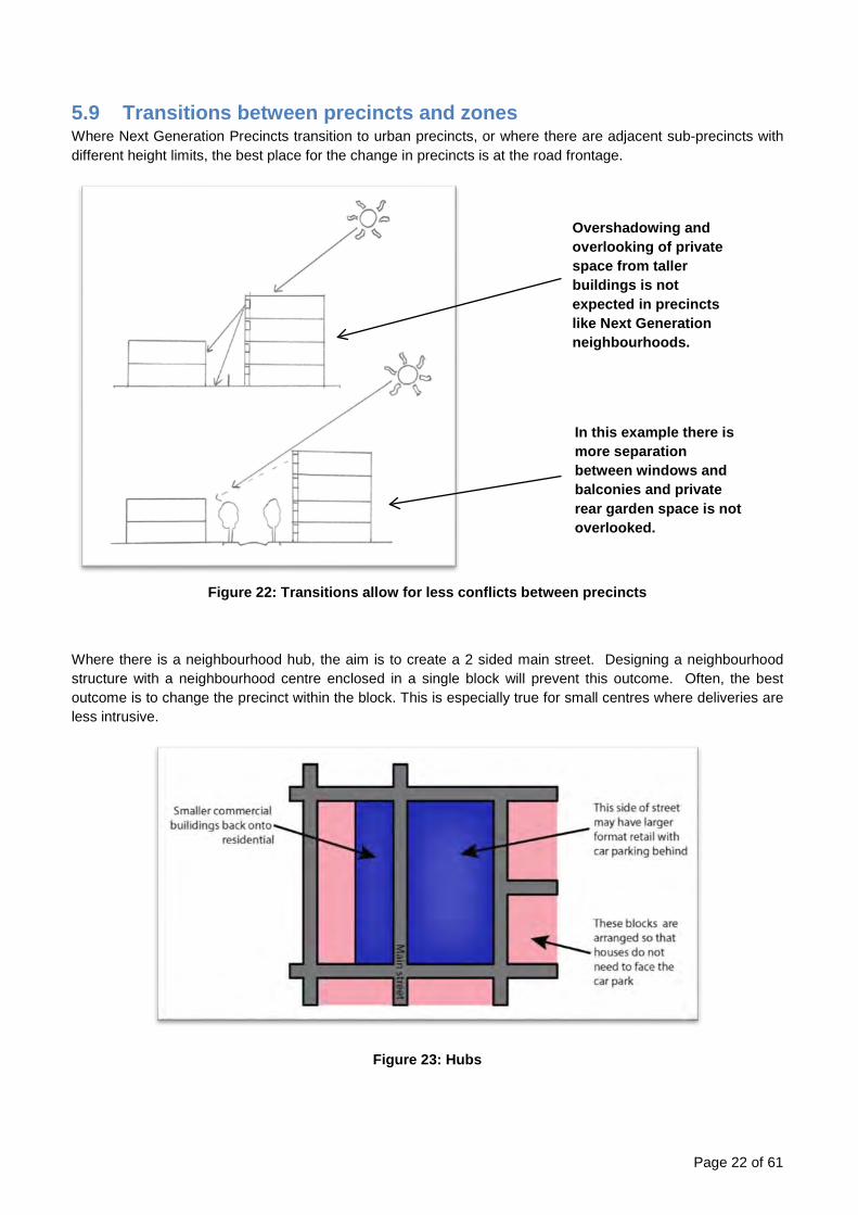
5.9 Transitions between precincts and zones Where Next Generation Precincts transition to urban precincts, or where there are adjacent sub-precincts with different height limits, the best place for the change in precincts is at the road frontage.
Figure 22: Transitions allow for less conflicts between precincts
Where there is a neighbourhood hub, the aim is to create a 2 sided main street. Designing a neighbourhood structure with a neighbourhood centre enclosed in a single block will prevent this outcome. Often, the best outcome is to change the precinct within the block. This is especially true for small centres where deliveries are less intrusive.
Figure 23: Hubs
Overshadowing and overlooking of private space from taller buildings is not expected in precincts like Next Generation neighbourhoods.
In this example there is more separation between windows and balconies and private rear garden space is not overlooked.
Page 22 of 61

5.10 Open Spaces Open spaces include Local, District and Regional Parks, linear parks, stormwater treatment areas and the Green Infrastructure Network. Together, these spaces contribute character, distinctiveness and natural beauty to a neighbourhood.
Parks
In assessing the need for parks, the following needs to be considered:
1 Future (forecast needs for open space). 2 Existing public space in and around the development area. 3 Any masterplanning or structure planning that has taken place for the area. 4 The need for linear parks or other connections.
Parks should be located to:
i. Maximise the number of people within a 5 minute walk (400metres) of a park
Figure 24: Local Park Access
Page 23 of 61
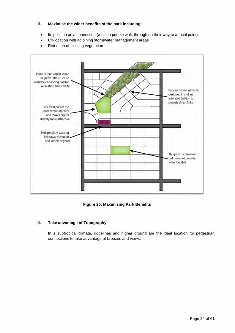
ii. Maximise the wider benefits of the park including:
• Its position as a connection (a place people walk through on their way to a focal point). • Co-location with adjoining stormwater management areas • Retention of existing vegetation
Figure 25: Maximising Park Benefits
iii. Take advantage of Topography In a subtropical climate, ridgelines and higher ground are the ideal location for pedestrian connections to take advantage of breezes and views.
Page 24 of 61

iv. Be Integrated with Centres
Where a neighbourhood includes a local centre, the centre should be integrated with open space if possible. The open space may take the form of:
• A local park co-located with the centre
Where parks are co-located, the centre and park should function as a single destination by including the following elements: o Integrated car parking that serves both destinations o Commercial buildings face the park directly, possibly across a road o Direct integration of facilities where possible (eg café seating spills out into the park
and overlooks a playground)
• A civic plaza integrated with the centre
A civic plaza is a small, more formal public space integrated directly with a commercial development, usually in the form of a town square. The civic plaza will be designed at the time of the development to:
o Be faced by active frontage on at least one side (not across a road) o Be located as an entrance feature, inviting people to walk through it on the way to the
centre o Be located adjacent to the main entrance to the shops
Page 25 of 61

5.11 Stormwater Locate stormwater management areas to increase the amount of open space in the development or to achieve ecological aims. Some ideas for achieving this are:
• As a feature next to a park, to create a larger open space: • Integrated with the Green Infrastructure Network • Raingardens and planted swales within the road corridor
Figure 26: Stormwater Locations
Page 26 of 61

5.12 Green infrastructure network (GIN) Green infrastructure is a network of natural, semi-natural and engineered green assets that are functionally connected across a landscape. A green infrastructure network contains areas and corridors of natural bushland, parkland, street and habitat trees, urban landscaping, permeable paving and even innovative design technologies including green roofs and walls.
The Green Infrastructure Network is both a constraint and an opportunity. It should be considered at an early stage so that:
• the existing natural values of the site can be incorporated into the network. • to maximise the amenity provided by the GIN.
The aim is to create a functional and connected network for wildlife movement. With this in mind, the design and layout of development should respond to the site. For instance roads may be positioned to incorporate existing trees into the road reserve.
Figure 27: Retention of existing trees
Road positioned to retain tree within
the verge Natural
Bushland
Page 27 of 61
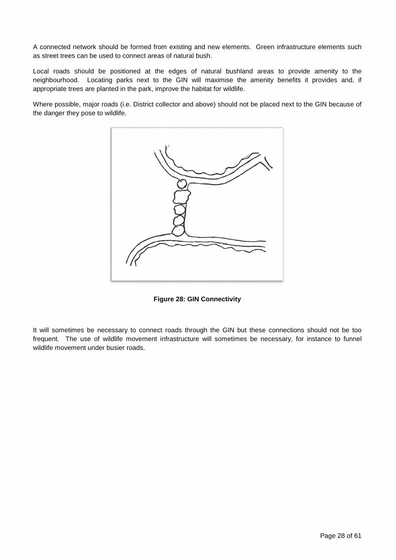
A connected network should be formed from existing and new elements. Green infrastructure elements such as street trees can be used to connect areas of natural bush.
Local roads should be positioned at the edges of natural bushland areas to provide amenity to the neighbourhood. Locating parks next to the GIN will maximise the amenity benefits it provides and, if appropriate trees are planted in the park, improve the habitat for wildlife.
Where possible, major roads (i.e. District collector and above) should not be placed next to the GIN because of the danger they pose to wildlife.
Figure 28: GIN Connectivity
It will sometimes be necessary to connect roads through the GIN but these connections should not be too frequent. The use of wildlife movement infrastructure will sometimes be necessary, for instance to funnel wildlife movement under busier roads.
Page 28 of 61
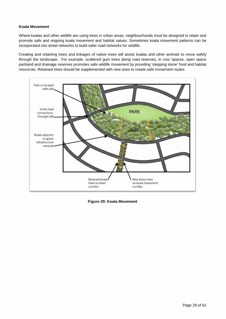
Koala Movement
Where koalas and other wildlife are using trees in urban areas, neighbourhoods must be designed to retain and promote safe and ongoing koala movement and habitat values. Sometimes koala movement patterns can be incorporated into street networks to build safer road networks for wildlife.
Creating and retaining trees and linkages of native trees will assist koalas and other animals to move safely through the landscape. For example, scattered gum trees along road reserves, in civic spaces, open space parkland and drainage reserves promotes safe wildlife movement by providing ‘stepping stone’ food and habitat resources. Retained trees should be supplemented with new ones to create safe movement routes.
Figure 29: Koala Movement
Page 29 of 61

5.13 Centres New centres must be designed as part of the neighbourhood. This means that suitable land should be set aside at first design stage that can serve as an attractive, walkable focal point for the neighbourhood. A land parcel suitable for a centre should:
• Have dimensions that allow shops to face the street directly • Be integrated with parks where possible • Be located adjacent to busier streets • Allow the provision of car parking and access in a way that is not dominant (usually it will be to the side
and rear). • Be accessible from all directions • Take advantage of any other local opportunities, such as linear parks providing good walking access.
Figure 30: Examples of commercial sites co-located with parks
The surrounding area should be designed to allow access to the centre, especially on foot and by bicycle.
This could mean:
• Orienting streets to focus on the centre. • Ensuring that walking routes to the centre are not blocked by earlier stages of development
Page 30 of 61

Where there is an existing centre that would serve the development, consideration must be given to how it will be accessed from the area.
Figure 31: Desire Lines and Accessibility
Previous development has compromised the accessibility of the centre
Desire lines cross the development site
diagonally
Centre Centre
Desire lines catered for in development
Page 31 of 61

6 Refining the Layout A layout plan (as described in section 6) is a first draft for the development, showing the possible locations for roads and other infrastructure.
Drawing a layout plan is an iterative process as all the different layout considerations must be taken into account. Making changes to one aspect of the design (such as the position of a park) will affect how the neighbourhood functions, and require subsequent changes to other aspects of the design (e.g. the road layout).
Figure 32: Initial Layout Plan
These roads (above) are the framework for access and a starting point. Once the main routes have been identified, the minor roads can be structured around them. Once an initial layout plan has been devised, it should be refined to ensure that it works for the type of development expected. Consideration should be given to matters such as the size of blocks and development densities.
Page 32 of 61

Figure 33: Layout Refinement
Once a road layout has been designed, the next stage is to consider the road formation (and refine the layout as necessary).
Figure 34: Possible road typologies – based on PSP - Integrated Design [Appendix A]
Page 33 of 61
7 Density Density has been used in three sections of the planning scheme; the Strategic framework, the General residential zone code and the Reconfiguring a lot code. The Strategic framework uses a land use intensity measure of ‘people and/or jobs per ha’ as well as residential densities to describe the vision. The Reconfiguring a lot code and the General residential zone code utilise the measure of residential densities (e.g. dwellings per hectare). The key focus in the Strategic framework is to plan for a future with reduced private vehicle dependence, but density is needed to support sustainable public transport and active transport networks. Research undertaken by Peter Newman and Jeffrey Kenworthy identifies a minimum threshold of urban intensity of 35 residents and/or jobs per hectare.1 Below this intensity the physical constraints of distance and time enforce car use. Above this intensity there is a higher inclination for a range of alternative modes of transport to be used for trips more frequently. 35 residents and/or jobs per hectare is a measure of activity intensity, the concentration of activities in a given area, which is related to the number of possible trip origins and destinations in an area and the energy/effort required to access goods and services within a given area. The lower the intensity of activity the further more people have to travel to more dispersed locations to access the goods and services they need and the greater likelihood that the only practical way of accessing those goods and services is the private motor vehicle. The Strategic framework uses place types to convey the overall outcomes, including activity intensity, intended to be achieved in a place. This in turn gives guidance, order, and structure about the land uses, building types and densities that can be combined to produce acceptable outcomes which achieve the long term planning aspirations of Council. The planning scheme identifies the variety of land uses, density, building forms and lot configurations generally consistent with the intended activity intensity of each place type. Because the planning intention of Council is to gradually raise the intensity of activity in selected place types (e.g. Urban neighbourhood place type) over time to greater than 35 people and/or jobs per hectare, some place types have a specified minimum density only. This will encourage development and redevelopment that brings more people and jobs into an area. Other place types (e.g. Coastal communities and Suburban neighbourhood place types) have a maximum density specified and have not been targeted for an increase in the intensity of activity because they are not centrally located or have an established low activity intensity. In these places the remaining development opportunities are unlikely to change the intensity of activity, therefore alternative modes of transport are unlikely to become viable in the planning timeframe. Other places types (e.g. next generation neighbourhood place types) seek to avoid uniformity in built form outcomes and therefore include a specified range of possible site densities.
Page 34 of 61

The table below lists the density targets used in the planning scheme for the residential place types and precincts previously described.
Density in the MBRC Planning
Scheme
Residential place types General residential zone precincts
Coastal Communities Place type/
precinct
Suburban Place type / precinct
Next generation Place type/
precinct Urban Place type /
precinct
Strategic Framework N/A
Max 11 dwellings/ha – Net residential density
35 people and/or jobs per ha (for people this equates to 15-25 dwellings/ha – Net residential density)
60 people and/or jobs per ha (for people this equates to Min 30 dwellings/ha – Net residential density)
Reconfiguring a lot code, Precinct overall outcomes
Max 11 lots/ha – Net residential density
Max 11 lots/ha – Net residential density
11-25 lots/ha – Net residential density
N/A lots/ha - *must not compromise the precincts future ability to achieve a minimum site density of 45 dwellings per hectare.
General residential zone code, Precinct
overall outcomes
Max 15 dwellings/ha – Site density
Max 15dwellings/ha – Site density
15-75 dwellings/ ha – Site density
Minimum 45dwellings/ha or minimum 75 dwellings/ha – Site density
To achieve the land use intensity described in the Strategic framework, reconfiguring a lot density and material change of use density occurring at the site level are layered together and combined with other planning provisions for non-residential land uses like parks, schools, centres and neighbourhood hub’s to create a land use intensity envisaged by the Strategic framework.
Page 35 of 61

Densities sought in the Reconfiguring a lot code for the Coastal Communities, Suburban and Next generation neighbourhood precincts are expressed as a number of lots per hectare rather than dwellings in recognition that at the reconfiguring a lot stage it is not always possible to know the ultimate development of each lot. However, density outcomes for reconfiguring a lot in the Urban neighbourhood precinct are different to the other precincts as the precinct will require either very small lots or very large lots to facilitate the higher densities sought. Accordingly, the outcomes for this precinct require the size of lots created ensures the minimum site density for the urban precinct can be achieved. The densities sought in the General residential zone code appear higher than those listed in the Reconfiguring a lot code because the code expresses density as a number of dwellings per hectare. This code applies to Material change of use applications and ensures a higher concentration of dwellings on site in order to achieve the residential density or land use intensity sought by the Strategic framework. It is important to remember that residential density is not always a reliable measure of built form intensity, nor is it the sole factor in place making. It is a tool to help inform good decision making and to help ensure objectives are met. It is not a reliable indication of how a place feels or functions. Density targets should not be applied as a blanket control on individual sites within a broader area. This would result in monoculture rather than variety. For this reason densities in the planning scheme are either a maximum, a minimum or include a range (e.g. 15 – 75 d/ha) to avoid their use as a ‘one-size fits all’ planning control. To meet housing diversity needs and make efficient use of land and services in Caboolture West, the Local plan code sets an average net residential density overall of 22 dwellings per hectare which combines the proposals for:
• Next Generation 20: Net residential densities between 15-25 dwellings per hectare with a minimum average of 20 dwellings per hectare; and
• Next Generation 30: Net residential density of a minimum average of 30 dwellings per hectare. This is a different approach to that used in the rest of the planning scheme, however it is intended to result in the same outcome, dwelling diversity.
7.1 How to measure density: Residential density can be measured in a number of different ways. All residential density measures are calculated using the same basic ratio formula: the number of dwellings divided by the area of land they occupy.
Residential density =
Number of lots/dwellings
Land area
These two residential density measures are referred to as “Net residential density” in the reconfiguring a lot code and “Site density” in zone codes. These residential densities are further described and defined below. The extent of land included in the land area determines the type of density measure used. Types of density measures and extent of land included:
• Site Density: includes only the residential component of the land area. Including internal access ways for community title developments. It is the most concentrated measure of density.
• Net Density: includes the residential component plus local roads and local parks. The planning scheme uses two residential density measures depending on the development (RAL or MCU) and the purpose of the outcome or the intent of the code.
Page 36 of 61
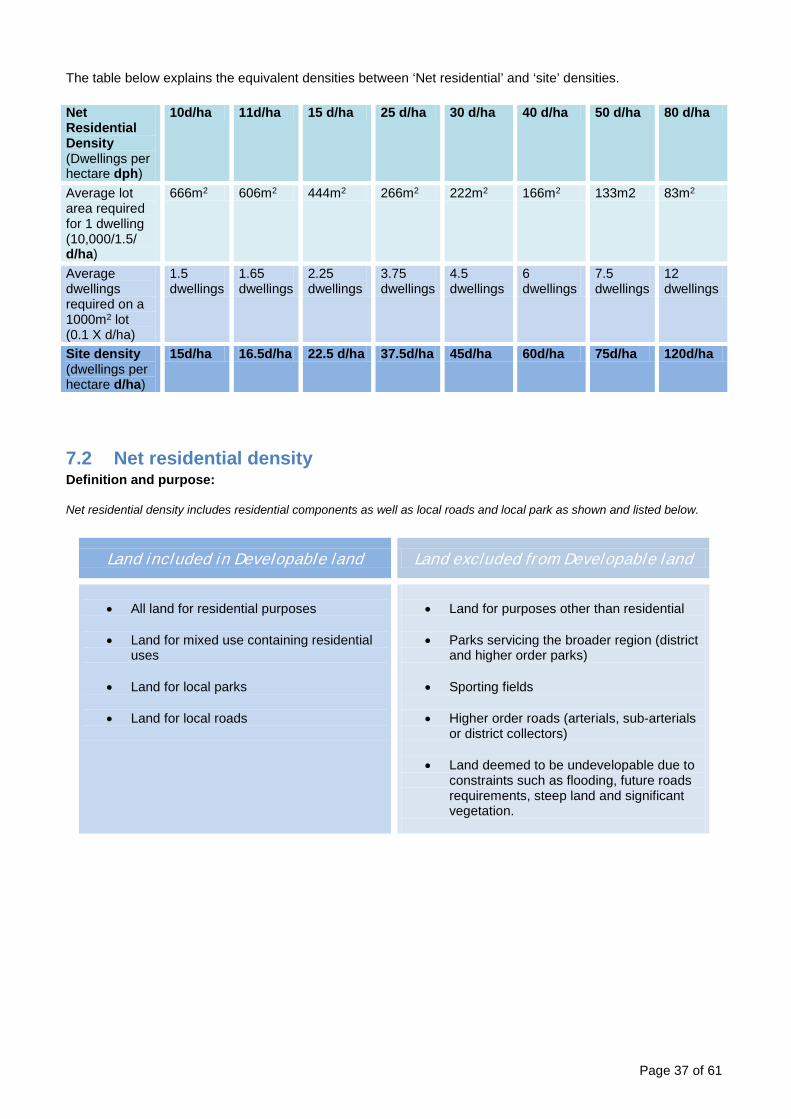
The table below explains the equivalent densities between ‘Net residential’ and ‘site’ densities. Net Residential Density (Dwellings per hectare dph)
10d/ha 11d/ha 15 d/ha 25 d/ha 30 d/ha 40 d/ha 50 d/ha 80 d/ha
Average lot area required for 1 dwelling (10,000/1.5/ d/ha)
666m2 606m2 444m2 266m2 222m2 166m2 133m2 83m2
Average dwellings required on a 1000m2 lot (0.1 X d/ha)
1.5 dwellings
1.65 dwellings
2.25 dwellings
3.75 dwellings
4.5 dwellings
6 dwellings
7.5 dwellings
12 dwellings
Site density (dwellings per hectare d/ha)
15d/ha 16.5d/ha 22.5 d/ha 37.5d/ha 45d/ha 60d/ha 75d/ha 120d/ha
7.2 Net residential density Definition and purpose:
Net residential density includes residential components as well as local roads and local park as shown and listed below.
Land included in Developable land Land excluded from Developable land
• All land for residential purposes
• Land for mixed use containing residential
uses
• Land for local parks
• Land for local roads
• Land for purposes other than residential
• Parks servicing the broader region (district
and higher order parks)
• Sporting fields
• Higher order roads (arterials, sub-arterials or district collectors)
• Land deemed to be undevelopable due to
constraints such as flooding, future roads requirements, steep land and significant vegetation.
Page 37 of 61

Figure 35: Net Residential Density Inclusions
Calculation:
Net Residential Density =
The total number of lots/dwellings
Developable land (hectares)
The combined area of residential lots, local parks, internal roads and half the roads bordering the site (or the site area x 1.5)
OR
Number of dwellings =
NRD X [site area (ha) X 1.5]
Example: A NRD of 15d/ha on a 0.5ha site (15d/ha x (0.5 x 1.5) equals 11 lots.
To calculate the net residential density of an individual site, allowance must be given for the area of local roads and parks. Using a ratio of 2:1 (residential land: local roads and park), the area of a site must be increased by a factor of 0.5 to translate site density to net residential density. The factor of 1.5 should not be used for sites with internal roads and public space such as community management schemes.
Page 38 of 61
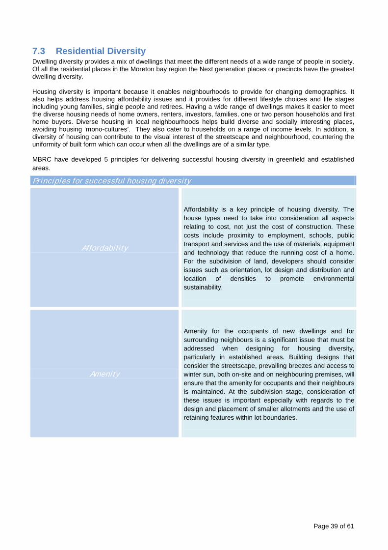
7.3 Residential Diversity Dwelling diversity provides a mix of dwellings that meet the different needs of a wide range of people in society. Of all the residential places in the Moreton bay region the Next generation places or precincts have the greatest dwelling diversity. Housing diversity is important because it enables neighbourhoods to provide for changing demographics. It also helps address housing affordability issues and it provides for different lifestyle choices and life stages including young families, single people and retirees. Having a wide range of dwellings makes it easier to meet the diverse housing needs of home owners, renters, investors, families, one or two person households and first home buyers. Diverse housing in local neighbourhoods helps build diverse and socially interesting places, avoiding housing ‘mono-cultures’. They also cater to households on a range of income levels. In addition, a diversity of housing can contribute to the visual interest of the streetscape and neighbourhood, countering the uniformity of built form which can occur when all the dwellings are of a similar type. MBRC have developed 5 principles for delivering successful housing diversity in greenfield and established areas.
Principles for successful housing diversity
Affordability
Affordability is a key principle of housing diversity. The house types need to take into consideration all aspects relating to cost, not just the cost of construction. These costs include proximity to employment, schools, public transport and services and the use of materials, equipment and technology that reduce the running cost of a home. For the subdivision of land, developers should consider issues such as orientation, lot design and distribution and location of densities to promote environmental sustainability.
Amenity
Amenity for the occupants of new dwellings and for surrounding neighbours is a significant issue that must be addressed when designing for housing diversity, particularly in established areas. Building designs that consider the streetscape, prevailing breezes and access to winter sun, both on-site and on neighbouring premises, will ensure that the amenity for occupants and their neighbours is maintained. At the subdivision stage, consideration of these issues is important especially with regards to the design and placement of smaller allotments and the use of retaining features within lot boundaries.
Page 39 of 61

Privacy
Privacy for the occupants of new dwellings and for surrounding neighbours is regularly raised as a major concern where smaller allotments and units are proposed. Appropriately designed dwellings will ensure that privacy, both visual and acoustic, is maintained, whilst not impeding active streetscape outcomes and neighbourhood interaction.
Wide Choice
The housing market for smaller homes is not limited to one particular house type or lot size. A wide range of housing product needs to be delivered to ensure that there is adequate choice for homebuyers at varying stages of life and in varying financial position, and to ensure diversity within the overall streetscape.
Salt and peppering
It is important that diverse housing forms are not clustered in only one location in a neighbourhood, but that they are dispersed in a variety of locations. There may still be localised ‘clustering’ of housing types, however, it should not be to an extent which clearly identifies an area as being different to otherwise similar areas. The secret to successful housing diversity is to normalise it.
Page 40 of 61

8 Putting Density and Diversity into practice during Reconfiguring a Lot
The following examples provide guidance on how the Reconfiguring of a lot outcomes can be achieved through the mix, location and density of suburban, next generation and urban precinct development in the General Residential Zone. These diagrams are for conceptual purposes only and should not be relied upon for justification against the Performance Outcomes of the Reconfiguring a lot code.
8.1 Suburban Neighbourhood Precinct
Figure 36: Conceptual Suburban Neighbourhood
Total Site Area 3.9 Ha
Total Lots 64
Average Lots / Block 12.8
Site Density 16 lots / Ha
Average Lot Size 609m2
Net Density 10.6 lots / Ha
Breakdown of lot types Lot Type (frontage width) No. of Lots
D >12.5 - 18m 16
E >18 - 32m 48
Page 41 of 61

8.2 Next Generation Neighbourhood Precinct
Figure 37: Conceptual Next Generation Neighbourhood
Total Site Area 3.9 Ha
Total Lots 99
Average Lots / Block 19.8
Site Density 25.4 lots / Ha
Average Lot Size 393m2
Net Residential Density 16.5 lots / Ha
Breakdown of lot types Lot Type (frontage width) No. of Lots % of total lots
A 7.5m 17 17.2 %
B >7.5 - 10m 20 20.2 %
C >10 - 12.5m 33 33.3 %
D >12.5 - 18m 19 19.2 %
E >18 - 32m 7 7.1 %
F >32m 3 3.0 %
Following Comprehensive Redevelopment of 30m+ frontage lots
Total dwellings 111
Average dwellings / block 22.2
Site Density 28 dw / Ha
Net Density 18.4 dw / Ha
Page 42 of 61
8.3 Urban Neighbourhood Precinct
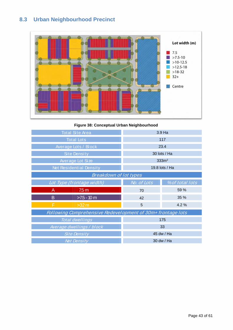
Figure 38: Conceptual Urban Neighbourhood
Total Site Area 3.9 Ha
Total Lots 117
Average Lots / Block 23.4
Site Density 30 lots / Ha
Average Lot Size 333m2
Net Residential Density 19.8 lots / Ha
Breakdown of lot types Lot Type (frontage width) No. of Lots % of total lots
A 7.5 m 70 59 %
B >7.5 - 10 m 42 35 %
F >32 m 5 4.2 %
Following Comprehensive Redevelopment of 30m+ frontage lots
Total dwellings 175
Average dwellings / block 33
Site Density 45 dw / Ha
Net Density 30 dw / Ha
Page 43 of 61
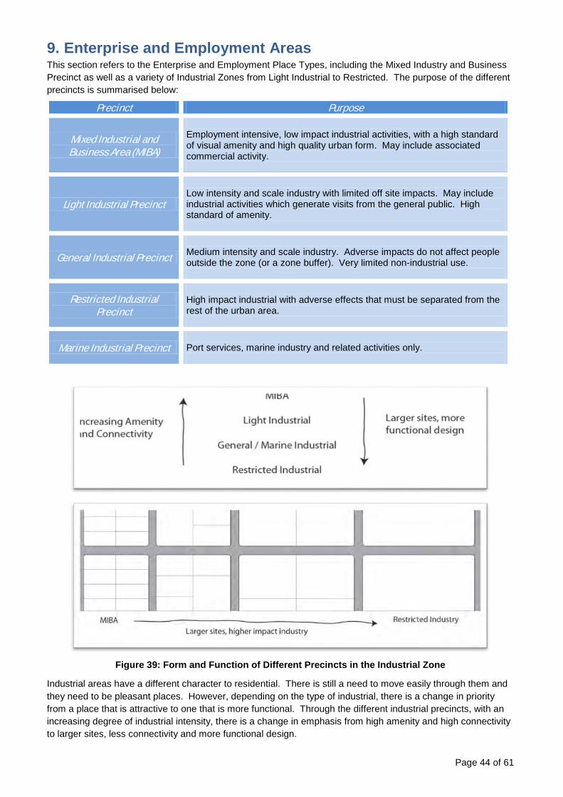
9. Enterprise and Employment Areas This section refers to the Enterprise and Employment Place Types, including the Mixed Industry and Business Precinct as well as a variety of Industrial Zones from Light Industrial to Restricted. The purpose of the different precincts is summarised below:
Precinct Purpose
Mixed Industrial and Business Area (MIBA)
Employment intensive, low impact industrial activities, with a high standard of visual amenity and high quality urban form. May include associated commercial activity.
Light Industrial Precinct
Low intensity and scale industry with limited off site impacts. May include industrial activities which generate visits from the general public. High standard of amenity.
General Industrial Precinct Medium intensity and scale industry. Adverse impacts do not affect people outside the zone (or a zone buffer). Very limited non-industrial use.
Restricted Industrial Precinct
High impact industrial with adverse effects that must be separated from the rest of the urban area.
Marine Industrial Precinct Port services, marine industry and related activities only.
Figure 39: Form and Function of Different Precincts in the Industrial Zone
Industrial areas have a different character to residential. There is still a need to move easily through them and they need to be pleasant places. However, depending on the type of industrial, there is a change in priority from a place that is attractive to one that is more functional. Through the different industrial precincts, with an increasing degree of industrial intensity, there is a change in emphasis from high amenity and high connectivity to larger sites, less connectivity and more functional design.
Page 44 of 61

9.1 Location Industrial zones will be located on major transport corridors.
There will usually be some degree of separation between industrial areas and the rest of the urban area. The importance of this depends on the intensity of the industrial use. MIBA, Light and Marine Industrial areas may contain businesses open to the general public, attracting more visitors than other industrial precincts. These areas need to be accessible and well integrated into the urban structure.
General and Restricted Industry are for more specialised industrial uses with few casual visitors and the need for a high degree of accessibility is less.
There is a need to manage this balance between the area being accessible, and managing the adverse effects it may create, particularly heavy vehicle traffic. Main road access should not be through residential areas, but there may be local road access to MIBA and light industrial.
The best way to achieve separation is through the use of use of natural barriers like roads, drainage and the Green Infrastructure Network to create separation. Paths, either walking and cycling or access roads, can be provided where appropriate:
Figure 40: Relationship of industrial land to its surroundings
Page 45 of 61

9.2 Structure Industrial zones should be part of the urban structure. They will be permeable and connected. They will have local facilities (such as local shops and cafes) located centrally where they are accessible within the industrial area. These hubs will be co-located with open space on main routes through the area.
Like residential neighbourhoods, industrial areas will be built with a grid connected road network, so they are easy to navigate and can be accessed on foot or by means of active transport. Using some 4-Way intersections helps to make a place navigable, especially if routes converge in a central place. This is often the best place for facilities like the neighbourhood hub.
Due to the scale of industrial activities and the lower intensity of use anticipated, the grid size expected is larger through the different types of industrial use.
Figure 41: Structure of Industrial Areas
MIBA – approx. 250 x
140 block size
Light Industry – approx. 300 x 150
block size
Central Facilities (Neighbourhood
Hub)
Pedestrian links to surrounding area
Link to local roads
M A I N R O
Central 4 way
intersection
Page 46 of 61

9.3 Movement Walking and Cycling Walking routes will be provided through industrial areas on the street network. The block structure of the network will ensure that there is good pedestrian access throughout. Blocks should not generally have a perimeter greater than 1km except for Restricted Industry.
Street trees and landscaping within the street corridors will provide shade and amenity to make walking a viable option.
Figure 42: Structure of Industrial Areas
Public Transport Public transport should be available within 400m of the majority of sites. This may be within adjacent roads, or on an internal road. Public transport should follow logical routes that are reasonably direct. Buses should not have to double back on themselves or follow convoluted paths.
Connections to main roads All industrial areas should be directly connected to the main road network. There may be connections to the local road network – however these should not be more attractive for heavy vehicles than the route to the main road (for instance by connecting directly to an alternative main road).
Page 47 of 61

Figure 43: Designing for Movement
9.4 Stormwater Design and locate stormwater management areas to provide some amenity to the area. Planted stormwater areas with trees add interest to the area and reduce the dominance of hard-surface and large scale buildings.
Stormwater management may be on site or in dedicated areas. Either way, it should be open and planted to provide visual amenity. An integrated approach is preferred to site by site solutions. Multiple properties can be served by larger detention basins
Some areas may be suitable for raingardens and these are an opportunity to enhance the street amenity, especially in higher amenity industry areas such as MIBA.
Some ideas for the location of stormwater areas are:
• As a central feature or landmark at a prominent junction. • Next to a road or walkway as a linear feature. • Next to and integrated with the Green Infrastructure Network. • Raingardens and planted swales in the road corridor (centrally located swales are preferred, especially
in areas other than MIBA).
Bus has logical route through centre of site
Pedestrian links to surrounding area
Grid based road network with direct routes for pedestrians
and vehicles
Centrally located facilities are well connected for walking and
public transport
M A I N R O A D
Page 48 of 61
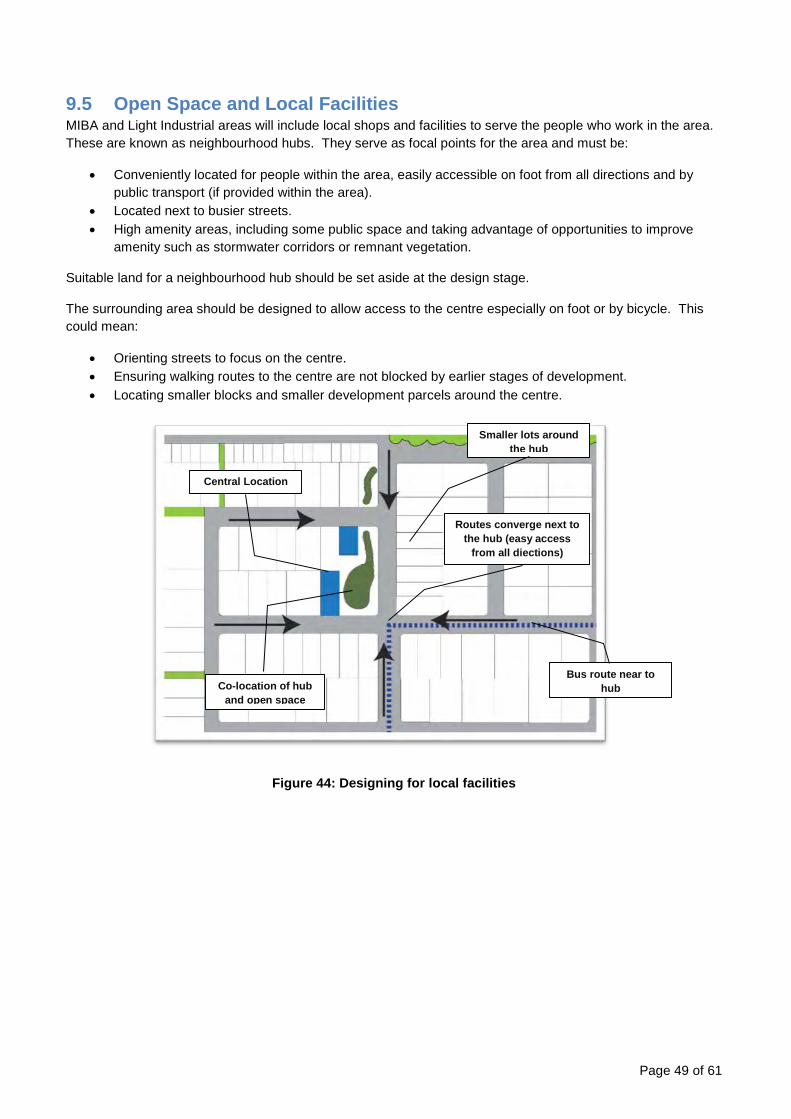
9.5 Open Space and Local Facilities MIBA and Light Industrial areas will include local shops and facilities to serve the people who work in the area. These are known as neighbourhood hubs. They serve as focal points for the area and must be:
• Conveniently located for people within the area, easily accessible on foot from all directions and by public transport (if provided within the area).
• Located next to busier streets. • High amenity areas, including some public space and taking advantage of opportunities to improve
amenity such as stormwater corridors or remnant vegetation.
Suitable land for a neighbourhood hub should be set aside at the design stage.
The surrounding area should be designed to allow access to the centre especially on foot or by bicycle. This could mean:
• Orienting streets to focus on the centre. • Ensuring walking routes to the centre are not blocked by earlier stages of development. • Locating smaller blocks and smaller development parcels around the centre.
Figure 44: Designing for local facilities
Smaller lots around the hub
Routes converge next to the hub (easy access
from all diections)
Bus route near to hub
Central Location
Co-location of hub and open space
Page 49 of 61

9.6 Retention of high value Vegetation High value vegetation must be retained and integrated into the design of the development. Keeping this vegetation will make the area more attractive and distinctive as well as maintaining ecosystem services. It will also provide shade and assist in stormwater management. Retained vegetation should be incorporated into the public realm, for example co-located with stormwater management or road corridors. The development should also connect the retained vegetation to any surrounding vegetation through the use of green corridors where possible, to allow wildfire to reach it. This can be achieved through the planting of suitable street trees or trees within stormwater management areas.
Figure 45: Designing for Remnant Vegetation and Wildlife
Remnant Vegetation
Developable land
Remnant trees form part of central focus next to neighbourhood hub
New trees link remnant vegetation to GIN
Page 50 of 61
Page 51 of 61
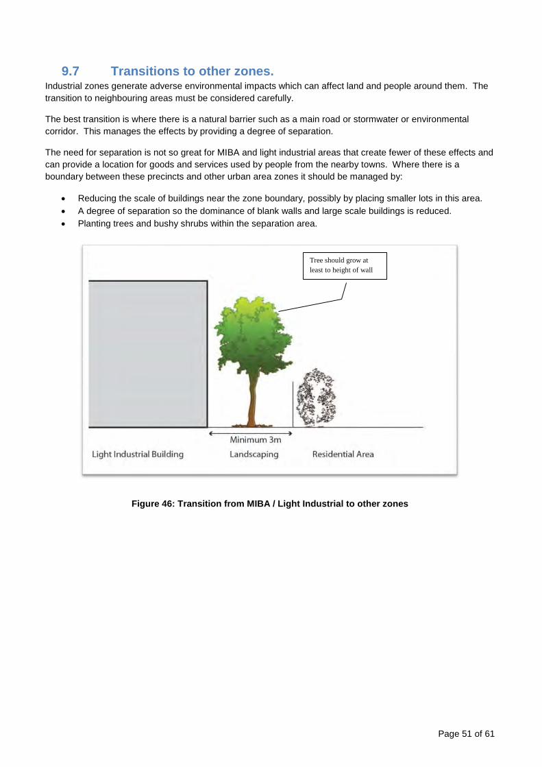
9.7 Transitions to other zones. Industrial zones generate adverse environmental impacts which can affect land and people around them. The transition to neighbouring areas must be considered carefully.
The best transition is where there is a natural barrier such as a main road or stormwater or environmental corridor. This manages the effects by providing a degree of separation.
The need for separation is not so great for MIBA and light industrial areas that create fewer of these effects and can provide a location for goods and services used by people from the nearby towns. Where there is a boundary between these precincts and other urban area zones it should be managed by:
• Reducing the scale of buildings near the zone boundary, possibly by placing smaller lots in this area. • A degree of separation so the dominance of blank walls and large scale buildings is reduced. • Planting trees and bushy shrubs within the separation area.
Figure 46: Transition from MIBA / Light Industrial to other zones
Tree should grow at least to height of wall

10 Neighbourhood development plans
10.1 Introduction The Caboolture West Structure Plan was prepared by Moreton Bay Regional Council in consultation with State Agencies following the Ministerial declaration of the Caboolture West Master Planned Area in February 2012. The Caboolture West Structure Plan has been included within Council’s new planning scheme as a local plan.
The Caboolture West local plan consists of 5 precincts and 15 sub-precincts. The location of the 5 precincts has been established as part of a comprehensive planning process (Shown on map LPM-03 contained in Schedule 2 of the MBRC planning scheme). The location of the 15 sub-precincts is required to be planned in more detail through the use of Neighbourhood development plans (NDP).
A NDP is the level of planning between the Caboolture West local plan and a development application. A NDP will show how the various sub-precincts, and places within the sub-precincts, are designed to form part of an overall integrated urban structure within the local plan area.
A series of figures are included within the Caboolture West local plan, which illustrate conceptually how Council intends the area will be developed. Neighbourhood development plans are intended to reflect these figures to show in detail the types, scale, timing and location of development and infrastructure prior to development occurring.
10.2 NDP areas The Caboolture West local plan area is split into 8 smaller areas, for which a Neighbourhood development plan is required. The preparation of each NDP is a serious planning and design exercise. The completion of all 8 NDP’s is expected to take place over a long period of time as development progresses through the local plan area.
The Figure below shows the 8 NDP areas along with colours indicating a conceptual sequence of expected plan preparation (dark to light), starting with NDP area 1 in the south east corner of the local plan area.
Page 52 of 61

Figure 47: Caboolture West Neighbourhood development plan areas
Page 53 of 61

10.3 NDP preparation process It is Council’s policy to require the preparation of a Neighbourhood development plan, in respect of development of land for urban purposes, prior to the issue of a development permit for a material change of use, reconfiguring a lot and operational work in accordance with the requirements of this policy.
The following steps outline the general process required to prepare a NDP. References are made to ‘Neighbourhood Design’ guidance material contained within the earlier sections of this planning scheme policy.
Step 1: Site context and environmental assessment
1.1 Establish the site context, major site features (e.g. land form, views, utility corridors, existing roads) and environmental constraints and opportunities (e.g. green network corridors, steep slopes, flood hazard, bushfire hazard, heritage and environmental values);
1.2 Produce a synthesised conditions analysis and establish the urban and non-urban areas for the NDP.
(Refer to Section 4 – Site Analysis for further information)
Step 2: External influences
2.1 Establish significant external connections to and from the site, such as existing roads, waterways, environmental corridors, view scapes and water catchments;
2.2 Identify external drainage and open space networks, existing and proposed facilities and services (e.g. schools and community facilities, services and centres) and employment opportunities and their relationship to the site;
2.3 Identify broad opportunities for integrated catchment management, the provision and multi-use of open space and non-residential facilities;
2.4 Produce a NDP context analysis that shows the main external influences and relationships with the NDP area that need to be factored into the NDP.
(Refer to Section 4 – Site Analysis for further information)
Step 3: Neighbourhood development, identity and integration
3.1 Identify the urban design typologies and relevant place types applicable to the NDP area;
3.2 Determine the location and nature of proposed and existing features and facilities, which will create focus and identity and achieve relatively self-contained, distinctive neighbourhoods with a strong ‘sense of place’;
3.3 Consider alternative development and density scenarios, which in turn, will influence the type, range and location of facilities and services to be provided (e.g. schools and centres);
3.4 Ensure that some flexibility is built into the various design options;
3.5 Define the preferred form of edge development to provide identity but also encourage integration with existing or future neighbourhoods.
(Refer to Section 5 – Neighbourhood Structure for further information)
Step 4: Movement and service connections
4.1 Identify the movement and service corridor policies and principles to be addressed in the NDP process;
4.2 Establish major local movement systems into and out of the NDP area;
4.3 Identify opportunities for bicycle and pedestrian movements through and beyond NDP area;
Page 54 of 61

4.4 Establish street connections to facilitate local and external movement and identify options for service connections;
4.5 Establish the basic movement network, linking existing streets where necessary and ensuring good local connectivity, permeability and legibility;
4.6 Ensure that motor vehicle networks do not dominate pedestrian and bicycle movements.
(Refer to Section 5 – Neighbourhood Structure for further information)
Step 5: Integrated and coordinated urban design processes and techniques
5.1 Use urban design workshop/urban design processes to bring together the outcomes of steps 1 to 4 to develop/refine land use strategies for the neighbourhood (Refer to Section 6 - Refining the Layout for further information);
5.2 Produce land use options at scales between 1:5,000 and 1: 1,000 as required to map out in detail the NDP;
5.3 Refine the design outcomes to a level that enables the NDP to be used as an “acceptable outcome”;
5.4 Check for vertical integration between elements in the NDP;
5.5 Check for horizontal integration between elements in the NDP;
5.6 Check for alignment with MBRC planning scheme outcomes;
5.7 Convert movement networks to a street and path layout, considering issues such as safety, legibility, environmental capacity, allotment layout and orientation, and climatic factors;
5.8 Convert precincts, sub-precincts and movement networks into detailed land use, and block layouts and land requirements for non-residential activities and facilities;
5.9 Determine benchmark development densities, broad distribution of lot sizes, housing types and intended built form outcomes.
Step 6: Infrastructure Provision
6.1 Determine the type, scale, location and timing of development;
6.2 Produce a staging plan;
6.3 Assess the availability and capacity of existing reticulated water and sewerage, electricity and telecommunications infrastructure;
6.4 Estimate the demand for infrastructure that will be generated and identify the most appropriate means for provision;
6.5 Estimate the degree of costs to be borne by the public and private sectors arising from development and where appropriate, establish agreements regarding infrastructure pricing policy and provision.
Step 7: Prepare and publish final NDP Documentation
Page 55 of 61

10.4 Planning elements to consider when preparing a NDP There are many planning elements to consider and address throughout all stages of the NDP preparation process. This information is detailed below, including associated tasks that may need to be undertaken such as identifying, describing and mapping the relevant element/s.
Further guidance can be taken from the neighbourhood design material contained within earlier sections of this planning scheme policy, as well as the planning scheme policy for integrated design, which outlines Council’s standards for the planning and design of streets, roads and public spaces.
1. Site context and environmental values (Refer to Section 4 – Site Analysis, for further information)
i) The NDP identifies, describes and maps:
a. the site context and major site features (e.g. views, landscape character assessment, remnant vegetation);
b. environmental constraints and opportunities (e.g. slopes, gullies, flood-prone land, bushfire hazard, areas of instability, and environmental values)(Refer to Section 5.12- Green Infrastructure Network);
c. the significant external connections to and from the NDP area, such as habitat corridors, view scapes and water catchments;
d. external drainage and open space networks, facilities and services (e.g. schools and community facilities, services and centres);
e. broad opportunities for integrated catchment management, the provision of multi-use open space and non-residential facilities;
f. existing and approved development; g. target population; h. housing needs; i. employment and business needs; j. community facilities and services needs.
ii) The NDP identifies, describes and maps how the development will:
a. respond to site characteristics, settings, landmarks and views; b. retain significant vegetation and habitat areas; c. retain major natural drainage paths (rivers, creeks and watercourses) in their natural condition; d. allow adequate buffers to development adjacent to major natural drainage paths; e. implement TWCMP; f. incorporate water sensitive urban design; g. integrate the green network into urban design outcomes; h. identify environmental offsets send and receive sites; i. protect, frame and incorporate strong views.
2. Protection of agricultural land i) Where the NDP area involves productive agricultural activities, the NDP will:
a. maintain existing lawful uses; b. avoid detrimental impacts on amenity of agricultural activities; c. avoid prejudicing the undertaking of agricultural activities; d. not disadvantage opportunities for future urban development of land used for agricultural
purposes.
3. Proposed land use (Refer to Section 5 – Neighbourhood Structure, for further information)
i) The NDP maps and describes the proposed land use structure including:
a. a land use budget that identifies a balanced provision of all necessary space requirements (existing and proposed) for each of the uses and activities that may be provided as determined in response to the assessment of local area conditions including:
• activity centres; Page 56 of 61
• employment areas; • community infrastructure; • residential development areas; • streets; • environmental areas; and • water cycle management proposed.
b. the predominate type, scale/density and location of development within each sub-precinct and the compatible/complementary mix of other land uses/services typically co-located with the predominant land use;
c. the land uses/services that are incompatible with the predominant land use in each sub-precinct;
d. the provision of centres, retail and commercial uses, community services and education facilities at focal points within convenient walking distance for residents;
e. a mix of lot sizes that enables a variety of housing types and densities; f. higher densities in areas close to services, public transport and public open space, or areas
with high levels of amenity; g. provide ancillary land uses; h. minimising the exposure of residential development to risks and hazards arising from the
impacts of incompatible uses and natural hazards in the area, including segregation of land uses, provision of buffers, residents’ exposure to electro-magnetic fields (from powerlines), exposure to noise from major roads, fire breaks etc.
i. integration with the surrounding area, including development of the connected street systems and active transport.
4. Neighbourhood design and built form (Refer to Section 5 – Neighbourhood Structure, for further information)
i) Neighbourhoods are:
a. scaled for an easy ‘five minute walk’ (400m) from the edge to the centre; b. ‘Next generation’ suburbs featuring diverse housing choice with a net density of at least 22
dwellings per hectare (Refer to Section 7 – Density and 8 - , for further information); c. clustered into groups of three or four within 800m of a local centre with boundaries which are
clearly defined by major features like the river, creeks, or major gullies; d. designed as distinctive places, providing attractive and safe living environments by
incorporating a mix of compatible facilities and services, jobs, schools, recreation.
ii) Neighbourhood design includes: a. a range of block shapes and variety to facilitate an efficient neighbourhood pattern and scale; b. connected streets and laneways; c. pedestrian and cycle way connectivity; d. the range of land uses identified as needed in the NDP area; e. housing choice within a neighbourhood and within a block; f. transition of building heights at the street and block; g. a table that specifies the broad distribution of lot sizes, lot mix and housing types to achieve
housing diversity; h. minimum site densities; i. street set back requirements j. sub-tropical design principles.
5. Street networks (Refer to Section 5 – Neighbourhood Structure, for further information)
i) The NDP maps and describes:
a. the existing transport network of the area; b. a permeable, legible, street and pedestrian/cyclist network providing connectivity, and property
access, walkable neighbourhoods, active transport and public transport services;
Page 57 of 61

c. a safe and convenient movement network within the local plan area and to and from the surrounding areas;
d. a safe and attractive pedestrian friendly built environment.
ii) The NDP includes a street network that has: a. an 800m grid of major streets, modified by topography, which provides a higher order street
network with district and regional connectivity; b. a 400m grid of local collector streets; c. a fine-grained connected street network within the grid to increase travel choices, and to
distribute and lower traffic on major streets so that all streets can support land use functions (e.g. housing) and qualities other than solely transport;
d. a hierarchy of 4-lane streets and 2-lane streets and laneways; e. limited access roads (Refer Section 5.5 – Interface with limited access roads); f. local streets designed to be suitable for bus routes; g. local connections to surrounding neighbourhoods.
iii) The NDP includes a PT network that:
a. connects the NDP area to adjoining areas; b. provides a network of local routes within 400m safe walking distance from existing or potential
dwellings that connects to local centres and community facilities; c. utilises local streets designed suitable for bus routes.
iv) The NDP includes an active transport network that:
d. includes a 200m grid of local access streets, on street pathways and off street pathways; e. provides a safe, convenient and legible network for pedestrians and cyclists; f. includes on-street cycle paths plus off-street walking and cycling paths on all major streets; g. includes an off-street path network taking advantage of the green network; h. connects destinations people want to go to around the town; i. is supported and well-connected by an 800m grid of streets.
6. Public open space and community facilities (Refer to Section 5 – Neighbourhood Structure, for further information)
i) The NDP maps and describes:
a. the existing public open space and community facilities within and adjacent to the NDP area; b. the forecast needs for public open space and community facilities in the NDP area; c. locational and design criteria for public open space and schools; d. the proposed community infrastructure needed in the area having regard to (a) and (b) above; e. the proposals contained in preceding Council master planning, structure planning relevant to
the NDP area; f. a land use budget that identifies balanced provision of all necessary public open space and
community facility space requirements (existing and proposed) including: i. primary and high schools; ii. regional and district sports; iii. district and local recreation park requirements; and iv. allowance for protection of and integration with environmental areas, and water cycle
management requirements.
ii) Park and open space planning and design: a. takes into account existing and forecast needs for park and open space in accordance with
Council’s strategic infrastructure planning requirements for the area; b. includes the size, type, distribution/location and site boundaries of all proposed parks and open
space; c. provides a legible network of public open spaces, links and pathways and preserves the river
and creek waterway and flood plains (land below the ultimate Q100 floodline);
Page 58 of 61

d. complements planning and design for the protection of the natural environment and landscape character by providing “stepping stones” for wildlife movement; retaining natural vegetation without compromising the role and function of the park to meet user needs;
e. is used to define the boundaries of the neighbourhoods and provide community focal points.
iii) Schools planning and design: a. takes into account existing and forecast needs for schools in accordance with State
government schools planning guidelines and requirements; b. includes the size, type, distribution/location and site boundaries of all proposed schools; c. using the locational and design criteria for schools integrate schools into the design of the
neighbourhoods including the park and open space, active transport, public transport and the street networks;
d. complements planning and design for the protection of the natural environment and landscape character by providing “stepping stones” for wildlife movement; retaining natural vegetation without compromising the role and function of the school site to meet user needs;
e. while non-government school locations are not identified they are assumed to adopt the same locational and design criteria as government schools.
7. Public utilities and other infrastructure i) The NDP maps and describes the existing and proposed public utilities and other infrastructure
required to support development of the NDP area including the type, scale, location and timing of: a. water supply; b. wastewater transport and treatment; c. power supply (electricity and gas); d. communication services; e. stormwater management system; f. existing natural wetlands; g. large dry detention basins of an appropriate size and shape to be adapted to passive
recreation.
ii) Public utility and other infrastructure is: a. located and designed to maximise efficiency, ease of maintenance, and minimum whole of life
cycle cost; b. provided in a timely, orderly, coordinated and integrated manner to support urban uses and
works; c. delivered in a manner that does not compromise the planned networks and hierarchies; d. co-located where reasonably practical; e. located and designed to minimise impacts on natural environmental values and integrated into
the design of distinctive, safe and attractive urban places; f. designed to create high quality living and working environments that are safe, convenient,
attractive, comfortable and fit for purpose.
8. Land ownership, development coordination and consultation i) Where the NDP involves multiple land owners the NDP will:
a. maintain existing lawful or mutually agreed access to third party lots; b. avoid detrimental impacts on amenity of third party lots; c. avoid prejudicing the development of third party lots by unreasonably shifting the costs of
infrastructure; d. guide and coordinate the staged development of the NDP area and the provision of necessary
infrastructure; e. include methods for continuing community involvement in plan preparation; f. remain current for development applications until Council endorses a new NDP.
Page 59 of 61

End Notes Amendment Number: 2 Adopted: 27 June 2017 Effective from: 3 July 2017 Planning Scheme Policy Reference
Summary of amendment
- • Amendment to reflect the terminology used in the Planning Act 2016, the Planning Regulation 2017 and related state planning instruments.
Page 60 of 61