plane-layered models for the analysis of wave propagation ... · plane-layered models for the...
TRANSCRIPT

Geophysical Prospecting, 1996 44, 3-26
Plane-layered models for the analysis ofwave propagation in reseruoirenvironmentsl
Jos6 M. Carc ione2
Abstract
The long-wavelength propagation and attenuation characteristics of three geo-logical structures that frequently occur in reservoir environments are investigatedusing a theoretical model that consists of a stack of fine and viscoelastic planelayers, with the layers being either solid or fluid. Backus theory properly describesfine layering and a set of fluid-filled microfractures, under the assumption thatinterfaces between different materials are bonded. The effects of saturation onwave attenuation are modelled by the relative values of the bulk and shear qualityfactors.
.The anisotropic quality factor in a fine-layered system shows a variety of behav-iours depending on the saturation and velocities of the single constituents. Thewave is less attenuated along the layering direction when the quality factors areproportional to velocity, and vice versa when inversely proportional to velocity.Fractured rocks have very anisotropic wavefronts and quality factors, in particularfor the shear modes which are strongly dependent on the characteristics of the fluidfilling the microfractures.
'$7hen the size of the boundary layer is much smaller than the thickness of the
fluid layer, the stack of solid-fluid layers becomes a layered porous media of theBiot type. This behaviour is caused by the slip-wall condition at the interfacebetween the solid and the fluid. As in Biot theory, there are two compressionalwaves, but here the medium is anisotropic and the slow wave does not propagateperpendicular to the layers. Moreover, this wave shows pronounced cusps alongthe layering direction, like shear waves in a very anisotropic single-phase medium.
Int roduct ion
A stack of plane and parallel layers is a useful model for studying the wave propa-gation characteristics of basic geological and rock structures. In particular, thesystems investigated in this work are predominant in reservoir environments at
I Paper presented at the 54th EAEG meeting, Paris, June 1992. Received October 1992, revisionaccepted April 1995.
2 osservarorio Geofisico Sperimentale, po Box 2011, opicina, I-3401 Trieste, Italy.
O 1996 European Association of Geoscientists & Ensineers

4 J.M.Carcione
different spatial scales. The theory may also be applied to the analysis of laminatedcomposite media and certain geological structures that contribute to the formationof sedimentary basins.
In a previous paper (Carcione 1992), the model was used to study the anisotropiccharacteristics of attenuation for waves propagating in a viscoelastic finely layeredmedium composed of two constituents. It is well known (Postma 1955) that whenthe thicknesses of the component layers are much smaller than the wavelength ofthe seismic pulse, a stratified medium can be replaced by an equivalent homoge-neous transversely isotropic medium. For a viscoelastic system, the complexstiffness matrix is given by Backus equations through application of the correspon-dence principle. Carcione (1992) calculated the energy velocities and quality factorsof the three propagating modes as a function of frequency and material propor-tions. He obtained in this way a model for describing anisotropic attenuation infine layering due to intrinsic loss mechanisms.
In this work, three realistic models built with a stack of viscoelastic plane solidand/or fluid layers are investigated. Wave attenuation is described by a continuousrelaxation model, giving an almost constant quality factor over a broad frequencyband. Firstly, attenuation in fine layering is analysed for cases where the qualityfactor Q is proportional to wave velocity, and then when Q is proportional to theinverse of the wave velocity. Rocks show different attenuation depending onwhether they are dry, saturated or partially saturated. In the first two cases, thequality factor of compressional waves is higher than the quality factor of shearwaves; the opposite occurs when rocks are partially saturated. These situations arealso investigated and, additionally, the characteristics of systems with more thantwo constituents are analysed.
A stack of two-constituent plane layers is used to describe a system of long andthin fluid-filled microfractures and cracks. This is an appropriate model becausecracks are likely to be preferentially aligned by a variety of non-lithostatic stressand stress-induced processes. Moreover, such fluid-filled cracks are usually rea-ligned by subcritical crack growth. The fracture-filling material is modelled by anon-Newtonian viscoelastic fluid represented by a 'soft' Kelvin-Voigt constitutiverelation whose rigidity is small compared to typical rock rigidities. This modelgives a complex viscosity appropriate for modelling the behaviour of fluids with
solid inclusions (colloid-type), and fluids in the presence of strong pore surfaceeffects. The model shows how the wave propagation characteristics of fracturedformations and rocks depend on the scale and frequency content of the probingpulse. For instance, the results apply to fluid-filled joints and fractured systems ofrotational symmetry distributed over large areas, or to wave propagation on asmaller scale, when fluids permeate the cleavage planes of metamorphic and sedi-mentary rocks. In all the cases, the quality factors due to intrinsic loss mechanismsshow anisotropic effects through preferred orientations. A similar model for frac-
tured systems (Schoenberg and Douma 1988) was shown to be effective even for
aspect ratios up to 0.3 and crack densities up to 0.03.
O 1996 European Association of Geoscientists & Engineers, Geophysical Prospecting, 44, 3-26
Plane-layered models for waae propagation analysis 5
The fracture model assumes that the skin depth of the boundary layer is muchlarger than the thickness of the fluid layers, or equivalently, that the wavelength ofthe viscous wave is much larger than the thickness of the fracture. When the skindepth is small in comparison with the thickness of the fracture, the model of alter-nating solid and fluid layers becomes a layered porous medium of the Biot type,where the solid is the matrix and the relative fluid proportion is the porosity(Schoenberg 1984). The model applies when the wavelength is much larger thanthe thickness of the pore, but much smaller than its length. This situation mayoccur for high frequencies in fractured limestones, where the aspect ratio of thepores is very low. Thus, the results may give an indication of the wave phenomenataking place at the microstructural level. The dynamic coupling between the solidand the fluid layers varies according to the propagation angle. For propagationperpendicular to the layers, only the fast wave propagates, corresponding to in-phase motion of the system. For angles out of the normal, the slow wave, with thesolid and fluid displacements 180' out of phase, starts to develop and reaches itsmaximum decoupling along the layering direction. The anisotropic and attenuationcharacteristics of these compressional modes are analysed as a function of the poro-sity and the dissipation properties of the solid and fluid phases.
Layered media with bonded interfaces
The model representing a stratified medium is made up of homogeneous isotropicplane layers which are perfectly bonded, i.e. there is no interfacial slip. Let there beN different materials, each one occupying the same proportion in a sufficientlylarge sample of stratified medium.
Let each single isotropic medium be anelastic with complex Lam6 parametersgiven by
A: (7 -r 3 p)M, - |p"M, and F: F'Mz,
where M, and M., arc dimensionless complex moduli in dilatation and shear,respectively, and ),'and,r.r'are the low-frequency limit Lam6 constants. The theoryassumes constant quality factors over the frequency range of interest. Such behav-iour is modelled by a continuous distribution of relaxation mechanisms based onthe standard linear solid (Ben-Menahem and Singh 1981). The dilatational andshear dimensionless complex moduli can be expressed as
(1 )
f -t /r + i<rrrr\ l- '
rr _ r )M " ( a ) : L t * ^ t " \ r + i a r r , / l ,
. - 1 , . , (2)
where r, and x2 are time constants, with rzltt, and Q, defines the value of thequality factor, which remains nearly constant over the selected frequency range.The low-frequency limit shows elastic behaviour with M" -+ 1; the high-frequencylimit is also elastic with r14" .-+ llll + (2nlQ) ln (rrlrr)1. The bulk and shear
O 1996 European Association of Geoscientists & Engineers, Geophysical Prospecting, 44,3-26
6 J.M.Carcione
quality factors are given by
o-:ff# and 0,:##
l r r r l l * c 5 5 t ! 0 ( c r 3 + c 5 ) t , 1 , ]
| 0 c u u l j + c 5 5 t j 0 l : u - p V 2 t r ,L(crr + cr5)1,1, 0 .r , 11+ cnt l ]
r3)
respectively, and the quality factor corresponding to the compressional wave is
^ R e ( 7 + 2 u \aP: rn e +t ; '
(4)
As illustrated in Fig. 1a, for l-in ) L (see Postma 1955; Carcione, Kosloff andBehle 1991), where 1-,n is the minimum wavelength, the stratified medium can bereplaced by an effective homogeneous transversely isotropic medium whosestiffness components c11 , I, J: l, ..., 6 are frequency-dependent and complex.The dependence of the c' on ,1. and p can be found in Backus (1962) or in Carcione(ree2).
The displacement of a general viscoelastic plane wave is of the form
u : IJo exp [i(rot - k ' x)], (5)
where r is the time variable, x is the position vector, and k is the complex wave-number vector defined bv
k : x - i c r : ( 6 )
with x and a being the propagation and attenuation vectors, respectively. \7henthese vectors are colinear, the wave is called homogeneous and the wavevector isgiven by
t : (rc - ia)ft = Aft, (7)
where
ft : /"6" + lyCy + l"C, (8)
defines the propagation direction through the direction cosines l*, lrand 1".Since the stratified medium has azimuthal symmetry, it is enough to consider
propagation in, say, the (x, e)-plane, for which ln: O. Then, the complex Christof-fel equation (e.g. Auld 1990) reads
(e)
where Z is the complex velocity. Equation (9) gives a complex dispersion equationwith three solutions, two coupled modes denoted by qP and qSV, representing thequasi-compressional and quasi-shear waves) and a pure shear (SH) mode, whosedisplacement vector is parallel to the layering. Expressions for the complex, phaseand energy velocities, attenuation factor, quality factor and slowness vector, in
O 1996 European Association of Geoscientists & Engineers, Geophysical Prospecting, 44,3-26

Plane-layered models for waae propagation analysis 7
(a)
g Averoging_
(b)
t r . n ) ) L
Averaging-+
L," ) ) L
(c)
il'f.l'lt{i!1W'f.i,.ffig$JEtlrifii,ffi ."'f ljiajr?lliit$!A{A{i.14.!f4r\:!{$Er&E{3}Tptt.lliti{liiirfr4tir:tt!"\ii
*i$�t#iiBif,#*fr h?,#.i,$!L#,ry#*fl EfEi,�,Efili
Averaging---.{>
t r . , " ) )Lt+4f fr EIE#H*tr+#?*HtTt#{i',r$iflii1i
Figure 1. (a) A stratified medium whose constituents are anelastic can be replaced by ahomogeneous medium with anisotropic wave attenuation when the minimum wavelength,t-,n is much larger than a sufficiently large sample of length l. (b) Backus theory can beused to describe a system of fluid-filled long and planar microfractures provided that thesize of the fluid boundary layer is greater than the thickness of the fracture. Moreover, if thefluid and the matrix rock are dissipative, the averaged system possesses an anisotropicintrinsic Q. (c) A model for layered porous media is obtained with alternating solid and fluidlayers, the solid representing the matrix and the fluid proportion, the porosity. At the long-wavelength limit, this model is a Biot anisotropic medium when the thickness of the fluidlayers is large in comparison with the viscous wavelength. In this case, the fluid can beconsidered practically ideal, and perfect interfacial slip takes place.
O 1996 European Association of Geoscientists & Engineers, Geophysicat prospecting, 44,3-26
llsi*,4Bliis;slFr*iT.$fr{sfii1-11r::1 lil j iir i i
Fluid-f illed microf ractu re
1ii !t;'rl#j|ilri11i t:ii,..i+,:,,

8 l.M.Carcione
terms of the complex stiffnesses c11 and propagation direction *, are given by Car-cione (1992). Since the equivalent medium is anelastic, the energy velocity (not thegroup velocity) is used to define the wavefront (see Carcione 1994).
Viscoelast ic i ty f ine ly layered media
The first example presents a stationary medium composed of limestone and sand-stone whose elastic properties, including density and wave velocities, are given inTable 1. Let the t ime constants in (2) be r r :0.16 s and12:3 x 10-a s, so thatthe quality factors are nearly constant over a broad frequency range including theexploration seismic band. Figure 2 shows zonal sections of the slownesses, energyvelocities and quality factors of the three wave modes in the equivalent medium, ata frequency of 25H2. The quality factors for the l imestone are Q, :80 and 0z:40, and for the sandstone, Qr:60 and Qr: 20, corresponding to fully saturated
0.2 0.3(S)x (s/Km)
Figure 2. Zonal sections of (a) the slowness, (b) energy velocity and (c) quality factor sur-faces for a fully saturated stratified medium. The medium is composed of limestone andsandstone with quality factors 0r : 80 and Qr: 40, and Q, : 60 and Qr: 20, respectively.The symbol (s, s) indicates that both constituents (limestone and sandstone) are fully satu-rated.
^ 0.3EYIN
a- 0 .2
O 1996 European Association of Geoscientists & Engineers, Geophysical Prospecting, 44,3-26

Energy Velocity (s,s)
60
50
40
(Ce)x (Km/s)
Quality Factor (s,s)
N
O J U
20
1 0
0
-"/ 1P
Nlqsv
\ "
0 1 0 2 0 3 0 4 0 5 0 6 0
(a)xFigure 2. Continued
(o 1996 European Association of Geoscientists & Engineers, Geophysical prospecting,44,3-26
6 e
Y
N
o- z

l0 J.M. Carcione
Table 1. Material Properties
Medium
1 e
(GPa)p ' g c p c s
(GPa) (Ke/m') (m/s) (m/s)
limestonesandstoneshale
3086.28
256t .70
270023002250
5443 30432949 16152074 869
rocks. The symbol (s, s) in Fig. 2 indicates that both constituents (limestone andsandstone, respectively) are fully saturated, such that
(s, s) : l(8r, Q)rr^,.,on", (0r, 0z)"unor,on"] : [(80, 40), (60, 20)]
in terms of the quality factors. The polarizations are plotted on the energy velocitycurves; when not plotted, they are normal to the plane of the figure (the polariza-tion vectors for anisotropic-viscoelastic media are calculated in Appendix A). Thedeviation of the viscoelastic polarization from the elastic polarization is shown inFig. 3 where Ay is the difference between the polarization angles with respect to thex-axis.
Figure 4 shows the results of all possible combinations of the quality factors; forinstance, both rocks being partially saturated means that (ps, ps) : [(40, 80),(20, 60)], and attenuation being inversely proportional to the velocity means that(s, s)i : [(60, 20), (80, 40)]. An example in which only one of the consrituents issaturated is given by (s, ps)i : [(60, 2O), (4O,80)]. In general, attenuation is higheralong the symmetry axis when the quality factors are proportional to the wave
-o.4
Figure 3. Deviation of the viscoelastic polarization from the elastic polarization for the qPwave. The angles are measured with respect to the ,-axis.
0.4
ol 0 .0
@) 1996 European Association of Geoscientists & Engineers, Geophysical Prospecting,44,3-26

l l
0 1 0 2 0 & . 0 s 6 0
lO)r
20 r0 60 r0(oI
0 r 0 2 0 3 0 4 0 5 0 6 0(o!
(oD
Figure 4. All possible quality factors for the limestone-sandstone system. Both constitu-ents being fully saturated is represented by (s, s) = [(80,40), (60,20)] in terms ofthe qualityfactors; partial saturation is represented by (ps, ps): [(40, 8O), (20, 50)]; attenuationinversely proportional to the velocity is represented by (s, s)i : [(60, 20), (gO, 40)]; and onlyone of the constituents being saturated is represenred by (s, ps)i : [(60, 20), (40, g0)].
O 1996 European Association of Geoscientists & Engineers, Geophysical prospecting,44,3-26

12 J.M. Carcione
velocity, and vice versa when the quality factors are inversely proportional to thevelocity. The coupled qSV shear mode has similar attenuation at the horizontal andvertical axes but is very anisotropic at intermediate directions.
The following example considers an equivalent transversely isotropic mediumcomposed of ten isotropic constituents whose material properties are obtained fromthe intermediate linear interpolated values of the limestone and shale rocks given inTable 1. The bulk quality factor varies from 0r: S0 (l imestone) to Qr:2g(shale), and the shear quality factor from @, : 60 to Qz : lO, when the system isfully saturated. Its physical properties are shown in Fig. 5. Compared to thelimestone-sandstone, this system is more anisotropic (in particular the qualityfactors). Figure 6 shows the quality factors for the partially saturated medium (a),
and for homogeneous Qz:50 (b). In this case, the uncoupled shear (SH) modehas isotropic attenuation, but the qSV mode is anisotropic due to the coupling withthe compressional wave.
(a)
^ ̂ Slowness (saturated rock)0.6
0.0 0 .1 0 .2 0 .3 0 .4 0 .5 0 .6
(S)x (s/Km)
Figure 5. Zonal sections of (a) the slowness, (b) energy velocity and (c) quality factor sur-
faces for a fully saturated stratified medium composed of ten constituents whose material
properties are obtained from the shale and limestone rocks given in Table 1. The bulk
quality factor varies from Q, : 80 (limestone) to Q, : 20 (shale), and the shear quality
factor from Qz: 6O to Q, : 16.
EYr2 0.3N
a
0.4
0.2
O f996 European Association of Geoscientists & Engineers, Geophysical Prospecting, 44,3-26

1 3Energy Velocity (saturated rock)
(Ce)x (Km/s)
Quality Factor ( saturated rock)
(a)xFigure 5. Continued
o 1996 European Association of Geoscientists & Engineers, Geophysical prospecting, 44,3-26
YN
ov z

40
N
o 3 u
20
1 0
0
30(a)x
0 1 0 2 0 3 0 4 0 5 0 6 0(a)x
Figure 6. (a) Zonal sections of the quality factor for a partially saturated rock composed often constituents. Partial saturation implies that the bulk quality factors are smaller than theshear quality factors. (b) As Fig. 5, but Q, : 50 for all the constituents.
N
O J U
O 1996 European Association of Geoscientists & Engineers, Geophysical Prospecting, 44,3-26

Plane-layered models for waae propagation analysis l5
Viscoelast ic f lu id- f i l led f ractured systems
Backus theory can be used to describe a system of fluid-filled long and planarmicrofractures, provided that the size of the fluid boundary layer is greater thanthe thickness of the fracture. Moreover, if the fluid and the matrix rock are dissi-pative, the averaged system possesses an anisotropic intrinsic e (Fig. 1b).
The shear complex modulus of a viscoelastic fluid can be modelled by a softKelvin-voigt rheology. The term 'soft'means that the rigidity modulus is muchless than the rigidities of typical rocks. This type of behaviour occurs when thefluid filling the cracks contains some kind of inclusion or colloidal suspension. Themodel can be represented by a spring of constant 1t, and a dashpot of viscosity 4parameterizing the Newtonian viscosity of the fluid (i.e. a Kelvin-Voigt model, seeBen-Menahem and Singh 1981). The behaviour of fluids in fractures of small sizemay depart from that of a Newtonian fluid (which is obtained when p --+ 0) due tostrong surface effects.
The complex modulus of the viscoelastic fluid is given by
- k : l t * ia4,
and the complex viscosity is defined by (e.g. Ferry 1970)
( 1 1 )
In contrast to ideal fluids, a real fluid with non-zero viscosity must satisfy a no-slipboundary condition. Near the solid-fluid interface, more precisely in the boundarylayer, viscous waves of shear character propagate with complex wavenumber givenby the frequency divided by the complex modulus (10), i.e.
A " : ( 1 (r2)
where pr is the fluid density. For a Newtonian fluid, 4* :4, and the wavelength ofthe viscous waves is
q * : + : q + +l0) 1(t)
.. l.p,' t l2 , t * '
(10)
(13))-
A - . : - : ) . r" Re (ft")
For oil at a pressure of 20 atm, the viscosity is 11 : 445 cp : 0.445 Kg/s/m, and thedensity is p :399 Kg/mt (winkler 1985). At the exploration seismic band, i.e. fora frequency of approximately 20 Hz, the viscous wavelength i" : 1.77 cm, and forfrequencies in the sonic band, say 2 KH4 the wavelength ,." : 0.17 cm. For brine,with 4
- 1 .p, and pr: 1040 Kg/-t, the viscous wavelengths are 0.8 mm and 0.0gmm, respectively, for the exploration and sonic frequency bands.
The model of fluid-filled fractures assumes that the interfaces are bonded byimposing the condition that the viscous wavelength be greater than the thickness of
O 1996 European Association of Geoscientists & Engineers, Geophysical prospecting, 44,3-26
2rt@Pr

16 J.M. Carcione
the fractures. From Backus equations, the averaged medium is transversely iso-tropic, but actually it is a special class with only three independent stiffnesses sinceca3 x c r r and c12 N c rz ,
The following example examines a fractured limestone (see Table 1 for the lime-stone properties) where the volume ratio of the fractures is assumed to be 10 s.
The complex bulk modulus of the fluid is simply )"1 : )'i Mp and the shearmodulus is given by (10). For oil and water, the elastic moduli are ):1.94 GPa
and ,i" :1.96 GPa, respectively, with a shear modulus modelled by one Kelvin-
Voigt element of rigidity 1r : 10 s GPa. The values of the quality factors are Q, :
40 and Qz:20 for the l imestone, and Q, :20 for bulk dissipations of the fluid.The wave characteristics of the oil-filled fractured system are shown in Fig. 7,
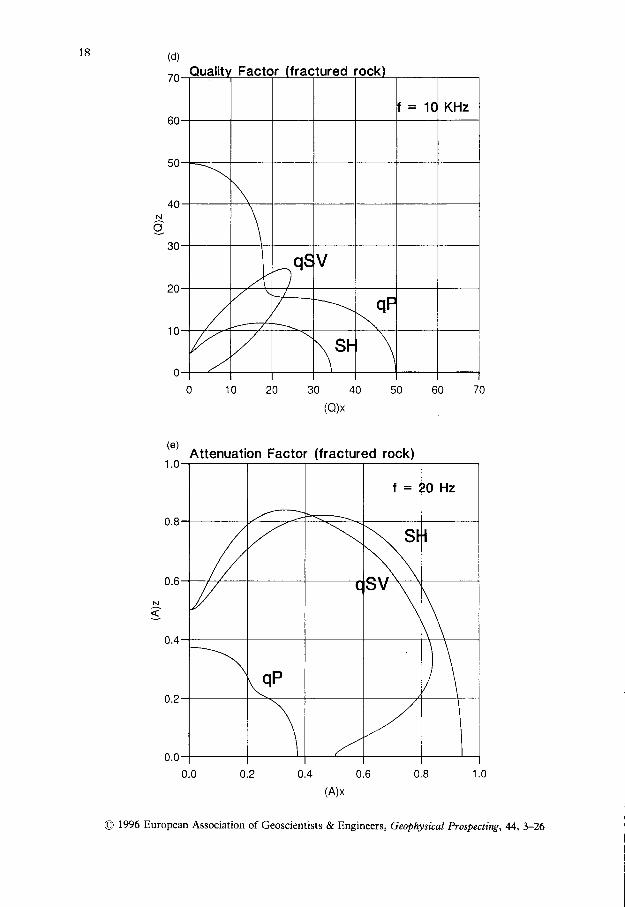
where the wavefronts are highly anisotropic, in particularly the shear modes. Theform of the quality factor curves changes substantially from 20 Hz to 10 KHz,governed by the characteristics of the fluid. This has a complex viscosity at lowfrequencies and behaves as a Newtonian fluid at high frequencies. $7hile the
Slowness fractured rock
0 .1 v , 1 0.3 0.4(S)x (s/Km)
Figure 7. Zonal sections of the (a) slowness, (b) energy velocity, (c) and (d) quality factor
surfaces and (e) attenuation for a fractured rock. The solid matrix is limestone and the fluid
is oil whose complex viscosity (or complex rigidity modulus) is modelled by a'soft" Kelvin-
Voigt rheology. The values of the quality factors are Q, :40 and Qt : 20 for the limestone,
and 0, : 20 for bulk dissipations of the fluid.
(a)
0.7
E 0.4:<o
N
g o . 3
0.70.60.50.0
(O 1996 European Association of Geoscientists & Engineers, Geophysical Prospecting,44' 3-26

t 7Energy Veloci ty ( fractured rock)
(c)
70
60
q n
40
30
20
1 0
00 1 0 2 0 3 0 4 0 5 0 6 0 7 0
(a)xFigure 7. Continued
O 1996 European Association of Geoscientists & Engineers, Geophysical Prospecting, 44,3-26
N
1 8
70
OU
50
40
30
fractured rock
(e)
1 . 0
(A)x
O 1996 European Association of Geoscientists & Engineers, Geophysical Prospecting, 44,3-26
N
1 0
0
(a)x
0.80.60.4o.2
Attenuation Factor (fractured rock)

Plane-layered models for wave propagation analysis 19
coupled modes are symmetric with respect to the propagation direction at 45o, thepure SH mode is not, but follows the shape of the slowness curve. For a water-filled limestone, the quality factor is shown in Fig.8; its characteristics are non-Newtonian at 10 KHz since the inertia term dominates the viscosity term in (11).In this case, the Newtonian behaviour is reached at higher frequencies.
Anisotropic and v iscoelast ic porous media
A model for layered porous media is obtained with alternating solid and fluidlayers, the solid representing the matrix, and the fluid proportion, the porosity. Inthe long-wavelength limit, this model is a Biot anisotropic medium when the thick-ness of the fluid layers is large in comparison with the viscous wavelength (Fig. 1c).In this case, the fluid can be considered practically ideal, and perfect interfacial sliptakes place. As a Biot solid, this system supports two compressional waves, the fastwave for which the solid and fluid displacements are in phase, and the slow wavewith displacements 180' out of phase (Fig. 9) (For a complete review of Biot theorysee Biot 1956; Bourbie, Coussy and Zinszner 1987). A Biot medium at very lowfrequencies does not support the slow wave since the viscosity effects dominate,
100
N
50
25
00 25 50 75 100 125 150
(Q)x
Figure 8. Quality factor for a water-filled fractured rock at l0 KHz. The only difference toFig. 7 is the value of the fluid viscosity, which is much less for water than for oil.
O 1996 European Association of Geoscientists & Engineers, Geopl4tsical Prospecting, 44,3-26

20 J.M. Carcione
Fast P-waveIn-phase displacementsW.:
:',,: :1;;:1;.i':11,t 'Wffi#ffi"# iii:iitiijii:lii)lill!:i!,i?ijttiitii
Slow P-waveOut of phase displacements
r::r. r i.: r r. I r..::: j l : i jr. j l j41]:r i;r j.rr :.
,,, :'.., 1 ,ll--;;:;1:;i.4q;41*4;.;111'. , ..1. '.
Figure 9. The anisotropic porous medium supports two compressional waves: the fastwave, for which the solid and fluid displacements are in phase, and the slow wave withdisplacements 180' out of phase.
and this mode becomes diffusive. \0?hen tangential slip takes place, the inertialeffects are predominant and the Biot slow wave is activated. Here the effects due toviscoelasticity of the solid and fluid layers can be investigated for typical relativedimensions of grain (solid) and pore (fluid) sizes, a task that cannot be carried outwithin the framework of Biot theory. Shear-wave propagation is not of interest,since the layered porous medium propagates shear waves only along the directionof layering, with the velocity of the solid (Brekhovskikh 1980).
The dispersion equation for the elastic layered system was obtained by Schoen-berg (1984). The viscoelastic system is obtained by substituting complex velocitiesfor the elastic velocities. The dispersion equation is
,. * {- *l&- *((;) . ffi)l+ 4,8(eE . *)\(#,")' : 0, (14)where Zp refers to compressional velocity, denoted by V, for the fluid, @ is theporosity, p, is the density of the fluid, and Vr1:2(l - V!1V!;rrzZ5 is the longwavelength complex velocity of extensional waves in an infinite plate, with I/, andV, the shear and compressional complex velocities of the solid, respectively. Thebracket operation ( ' ) denotes thickness weighted average.
Equation (14) has two physical solutions, corresponding to the fast and slowcompressional waves. The medium is anisotropic since the density is a transverselyisotropic tensor with effective density (p) normal to the layering, and effectivedensity (llp)- I parallel to the layering.
The phase velocity is the frequency divided by the real wavenumber. As in thebonded interface case (Carcione 1992), its magnitude is given by
(1s)' ,: [*'
(;)] '
@) 1996 European Association of Geoscientists & Engineers, Geophysical Prospecting, 44,3-26
Plane-layered models for waae propagation analysis
Similarly, the magnitude of the attenuation vector is given by
(16)
An energy analysis is beyond the scope of this work. Thus, a precise formula for
the wave surface as given by the energy velocity will not be developed. Similarly, itis not clear whether the expression for the quality factor obtained from the Backus
model (Carcione 1992) applies to this case. Attenuation and wave surfaces aredescribed by the absorption coefficient and the group velocity, the latter represent-ing an approximation of the wavefront surface for anelastic media. The formula forthe group velocity surface is obtained in Appendix B.
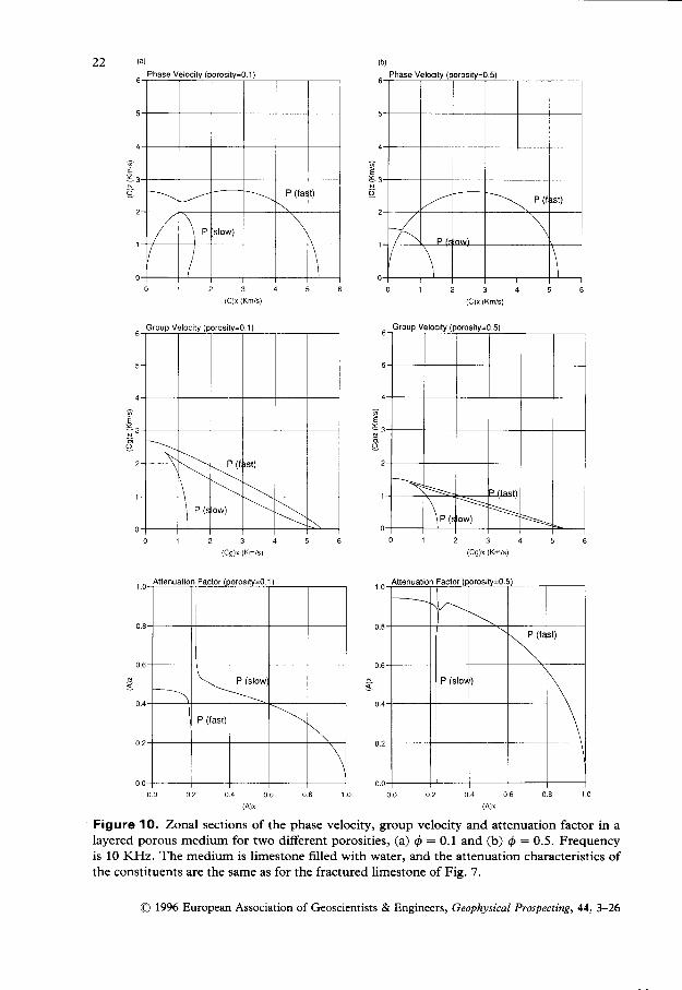
The following example considers a limestone matrix filled with water. Theattenuation characteristics of the constituents are the same as for the fracturedlimestone with the difference that here the rigidity modulus of the fluid is negligi-
ble, and therefore the viscous skin is much smaller than the size of the pores.
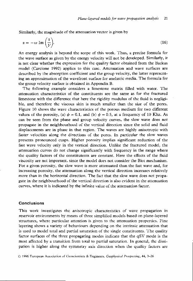
Figure 10 shows the wave characteristics of the porous medium for two differentvalues of the porosity, (a) 0:0.1, and (b) d:0.5, at a frequency of 10 Khz. Ascan be seen from the phase and group velocity curves, the slow wave does notpropagate in the neighbourhood of the vertical direction since the solid and fluiddisplacements are in phase in that region. The waves are highly anisotropic withfaster velocities along the directions of the pores. In particular the slow wavespresents pronounced cusps. Higher porosity implies significant reduction of thefast wave velocity only in the vertical direction. Unlike the fractured model, theattenuation curves do not change significantly with frequency in the range wherethe quality factors of the constitutents are constant. Here the effects of the fluidviscosity are not important, since the model does not consider the Biot mechanism.For a given porosity, the slow wave is more attenuated than the fast wave and, forincreasing porosity, the attenuation along the vertical direction increases relativelymore than in the horizontal direction. The fact that the slow wave does not propa-gate in the neighbourhood ofthe vertical direction is also evident in the attenuationcurves, where it is indicated by the infinite value of the attenuation factor.
Conclus ions
This work investigates the anisotropic characteristics of wave propagation inreservoir environments by means of three simplified models based on plane-layeredstructures, where particular attention is given to the attenuation properties. Finelayering shows a variety of behaviours depending on the intrinsic attenuation thatis used to model total and partial saturation of the single constituents. The qualityfactor surfaces of the three propagating modes indicate that the qSV mode is themost affected by a transition from total to partial saturation. In general, the dissi-pation is higher along the symmetry axis direction when the quality factors are
O 1996 European Association of Geoscientists & Engineers, Geophysical Prospecting, 44,3-26
21
-''- (#)
22Phase Velocily (porosity=o.5)
2 3
(C)x (Km/s)
(Cg)x (Km/s)
0 0 0 2 o - o
, o , ,
o u 0 8 1 0 0 0 0 2 o '
, o , ,
o u 0 8 1 0
Figure 1O, Zorral sections of the phase velocity, group velocity and attenuation factor in alayered porous medium for two different porosities, (a) Q:0.1 and (b) d :0.5. Frequencyis l0 KHz. The medium is limestone filled with water, and the attenuation characteristics ofthe constituents are the same as for the fractured limestone of Fig. 7.
6
5
EA
s2
1
0
E
O
\\
\ ' 'rw)
\
0 . 0 0 . 2 0 . 4 0 . 6 0 . 8 1 0
O 1996 European Association of Geoscientists & Engineers, Geophysical Prospecting,44,3-26

Plane-layered models for wave propagation analysis 23
proportional to the wave velocities, and vice versa when inversely proportional tothe velocity. On the other hand, the energy velocity surfaces are not substantially
affected by the intrinsic dissipation. This implies that the attenuation surfaces canbe better indicators of the direction of layering, and its degree of saturation, thanthe respective wavefronts.
Similarly, the attenuation in fluid-filled fractured rocks, where the fluid isexplicitly modelled by a thin layer, strongly depends on the frequency range andthe fluid viscosity. r,l7hen viscosity effects dominate (i.e. at high frequencies), theshear waves are highly attenuated perpendicular to the fracture strike. Ifhen theinertial term is predominant (i.e. at low frequencies), the qP wave presents, ingeneral, the highest dissipation along all the propagation directions.
Layered porous media describe the wave behaviour on a local scale assumingthat the pores are of planar shape. In this context, the wavefront and attenuationare very anisotropic, the anisotropy increasing with increasing porosity. The pro-pagation of the slow wave is forbidden along the direction perpendicular to thelayering, and its wavefront resembles a cuspidal triangle similar to the cusp of aqSV wave in a single-phase anisotropic medium. The implementation of these
rheologies into modelling codes should give support to the theory and more insight
into the physical processes involved.
Acknowledgements
This work was funded in part by the European Commission in the framework of
the JOULE programme, sub-programme Advanced Fuel Technologies. I thank
Julie Hood and Joe Dellinger for very detailed reviews of the article.
Appendix A
Polar izat ions in anisotropic-v iscoelast ic media
Polarization of the different wave modes in the (x, a)-plane can be calculated from
the Christoffel equation (9). The SH mode is polarized only along the y-direction,
while the coupled modes have components exclusively in the (x, e)-plane. The first
line of (9) yields
(crr t f ; + cssl2 * pv2)u" + (c13 f cr5) l" l ,u": o. (A1)
It is clear that the complex vector ll,O,u"fu,]a is also an eigenvector of the Chris-
toffel equation (9). Then, the normalized polarizations vectors of the coupled
modes are
{1 + [Re (B-)] t ] - t , '11,0, Re (B.) l r , m : 1 , 2 ,
O 1996 European Association of Geoscientists & Engineers, Geophysical Prospecting, 44,3-26
(42)

24 J.M. Carcione
where
B - : - c , , 1 . 1 + c r r l ? - P v 2 ^ -' ( c r r * r r r ) t - t " ' ( 4 3 )
and where m: I and m:2 correspond to the qP and qSV waves, respectively.The SH polarization vector is perpendicular to the (r, e)-plane.
The deviation of the viscoelastic polarization from the elastic polarization can bequantified by computing the difference between the polarization angles withrespect to the r-axis.
Ly(a, 0): arctan [Re (Br(ar, O)] - arctan [Br(0, A)],
whe re0 :a rccos ( / , ) .
(A4)
Appendix B
Group veloc i ty for a l ternat ing sol id and f lu id layers
The group velocity is the velocity of the modulation envelope of the wave and, asin the elastic case) can be expressed by
^ A a t ^ 0 a ^ 0 ace : € , i l - * ey "_ * € , _ , (B l )- oK* ' oK, oK,
where the spatial derivatives are taken with respect to the real wavenumber. Since areal explicit relationship of the form co : QR(rc" , Kr , K ") is not available, (B 1 ) is notappropriate. Alternatively, the group velocity can be obtained by implicit differen-tiation of the dispersion relation (14). For instance, for the ,c-component,
dar _ (dr , \ - rd. , : \a , ) G2)
or, since rc, : Re (fr,),
. 1 . . . f / r r \ - ] I
+ : l n . { i : } ldK, L \dol l
(83)
Implicit differentiation of the complex dispersion relation dl(k*, ku, k,, a):egrves
laa -l ^ o a\oa)
Thus,
(*)r" r"
* #uu')r, ,r , : o' (84)
0Al)ota$lak"' (Bs)
O 1996 European Association of Geoscientists & Engineers, Geophysical Prospecting, 44,3-26

Plane-layered models for wave propagation analysis 25
and similar relations hold for the fr, and k, components. Replacing the partial
derivatives in (B1), the group velocity can be evaluated as
",: _{u"[*(y*o))'
+e,[n. We)] '*c.[n.
(##.)]'\For the alternating solid-fluid layered system, the complex dispersion relationshipis obtained from (14) and the expression for the complex wavevector is
(B6)
(B7)k :? (1,6, + t"6").
Thus,
{ l ( k " , k , , a ) : .#)4,u1(#-*l# (88)
The evaluation of the group velocity from (86) is performed first through explicitcalculation of the partial derivatives, and then by numerical evaluation of the finalformula. The calculation of the partial derivatives with respect to the wavenumbercomponents is straightforward, while dQl1at requires more effort because eachcomplex velocity in (B8) is frequency-dependent. Since only squared velocitiesappear in the formula, the last step of the calculation includes the explicit deriv-atives of the dimensionless moduli (2), which are
.-'(GG) .ffi)1.-^(h):o
(Be)
References
Auld B.A. 1990. Acoustic Fields and Waoes in Solids, Vol. .1, 2nd edn. Robert E. KriegerPubl. Co.
Backus G.E. 1962. Long-wave elastic anisotropy produced by horizontal layering. Journal ofGeophy sical Research 67, 44274440.
Ben-Menahem A.B. and Singh S.J. 1981. Seismic Waaes and Sources. Springer Verlag, Inc.Biot M.A. 1956. Theory of propagation of elastic waves in a fluid-saturated porous solid. I.
Low-frequency runge. Journal of the Acoustical Society of America 28, l6Fl78.Bourbie T., Coussy O. and Zinszner B. 1987. Acoustics of Porous Media. Institut Francais
du Petrole Publications.Brekhovskikh L.M. 1980. Waves in Layered Media,2nd edn. Academic Press, Inc.Carcione J.M. 1992. Anisotropic Q and velocity dispersion of finely layered media. Geophys-
ical Pr o sp ecting 40, 7 6l-7 83.
e 1996 European Association of Geoscientists & Engineers, Geophysical Prospecting, 44,3-26

25 J.M. Carcione
Carcione I.M. 1994. Wavefronts in dissipative anisotropic media. Geophysics 59,64H57 .carcione J.M., Kosloff D. and Behle A. 1991. Long-wave anisotropy in stratified media: A
numerical test. G eophy sics 56, 245-254.Ferry J.D. 1970. Viscoelastic Properties of Polyrners. John \7iley & Sons, Inc.Postma G.!7. 1955. Vave propagation in a stratified medium. Geophysics 20,780-806.Schoenberg M. 1984. Wave propagation in alternating solid and fluid layers. Waoe Motion
6,303-320.Schoenberg M. and Douma J. 1988. Elastic wave propagation in media with parallel frac-
tures and aligned cracks. Geophysical Prospecting 36,571-590.\Tinkler K.W. 1985. Dispersion analysis in Berea sandstone. Journal of Geophysical Research
89,11549-11559.
@) 1996 European Association of Geoscientists & Engineers, Geophysical Prospecting, 44,3-26