planar -2d 12/24 air heater planar-4dm2-12/24 …1 application / modification . application of air...
TRANSCRIPT
www.autoterm.ru
Air heater
Installation Instructions
PLANAR-2D-12/24
PLANAR-4DM2-12/24-P
PLANAR-44D-12/24-GP-P
PLANAR-8DM-12/24-P
2
Contents
Connections Diagram PLANAR-2D 3
Connections Diagram PLANAR-4DM2 4
Connections Diagram PLANAR-44D 5
Connections Diagram PLANAR-8DM 6
Introduction 7
Application / modification 7
Safety 8
Installation 9
PLANAR-2D Heater Dimensions 10
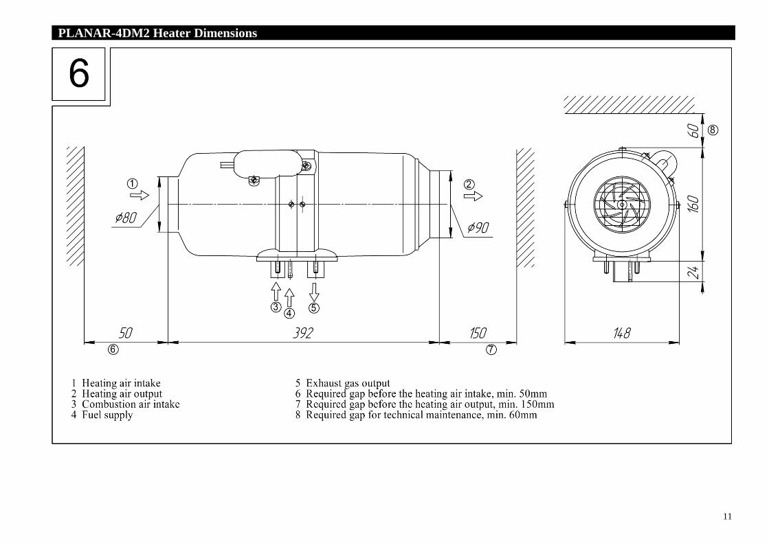
PLANAR-4DM2 Heater Dimensions 11
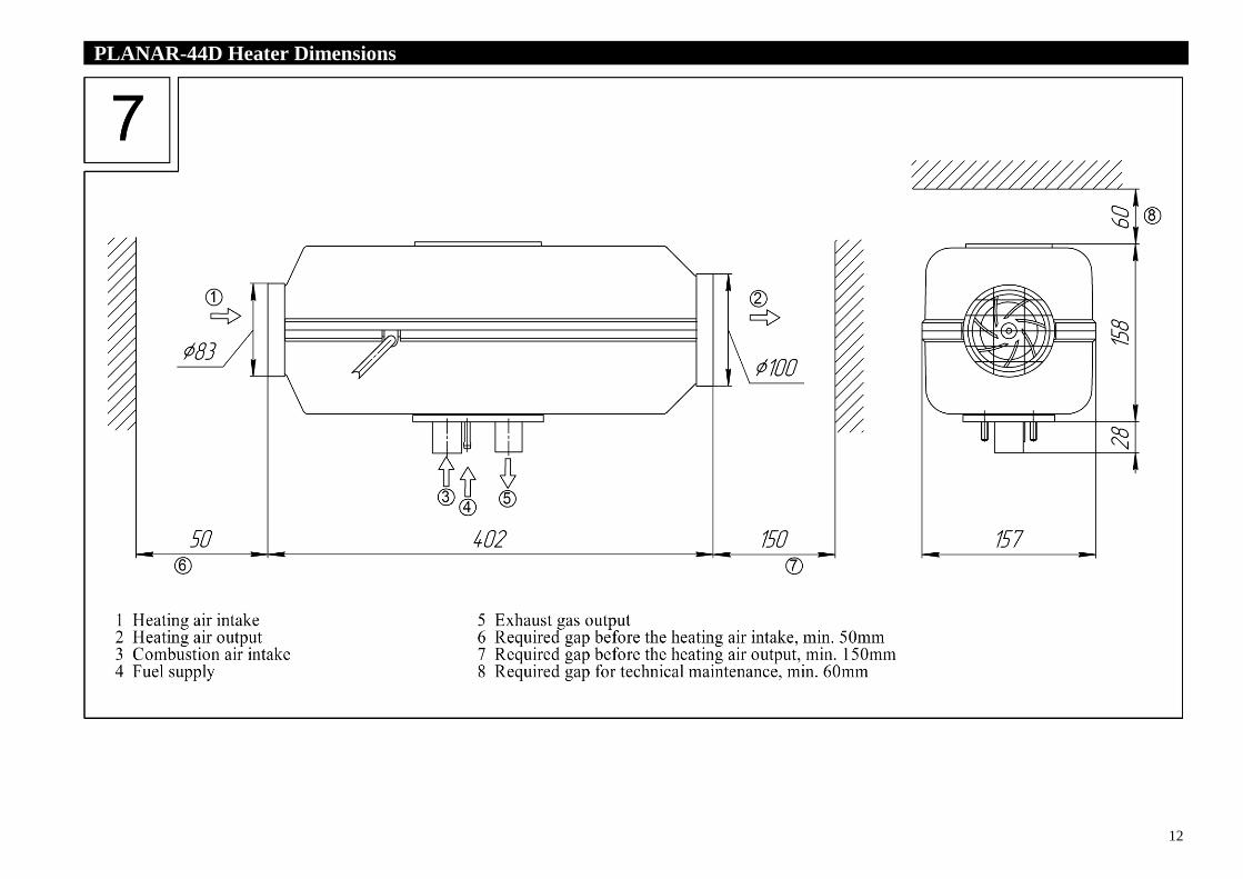
PLANAR-44D Heater Dimensions 12
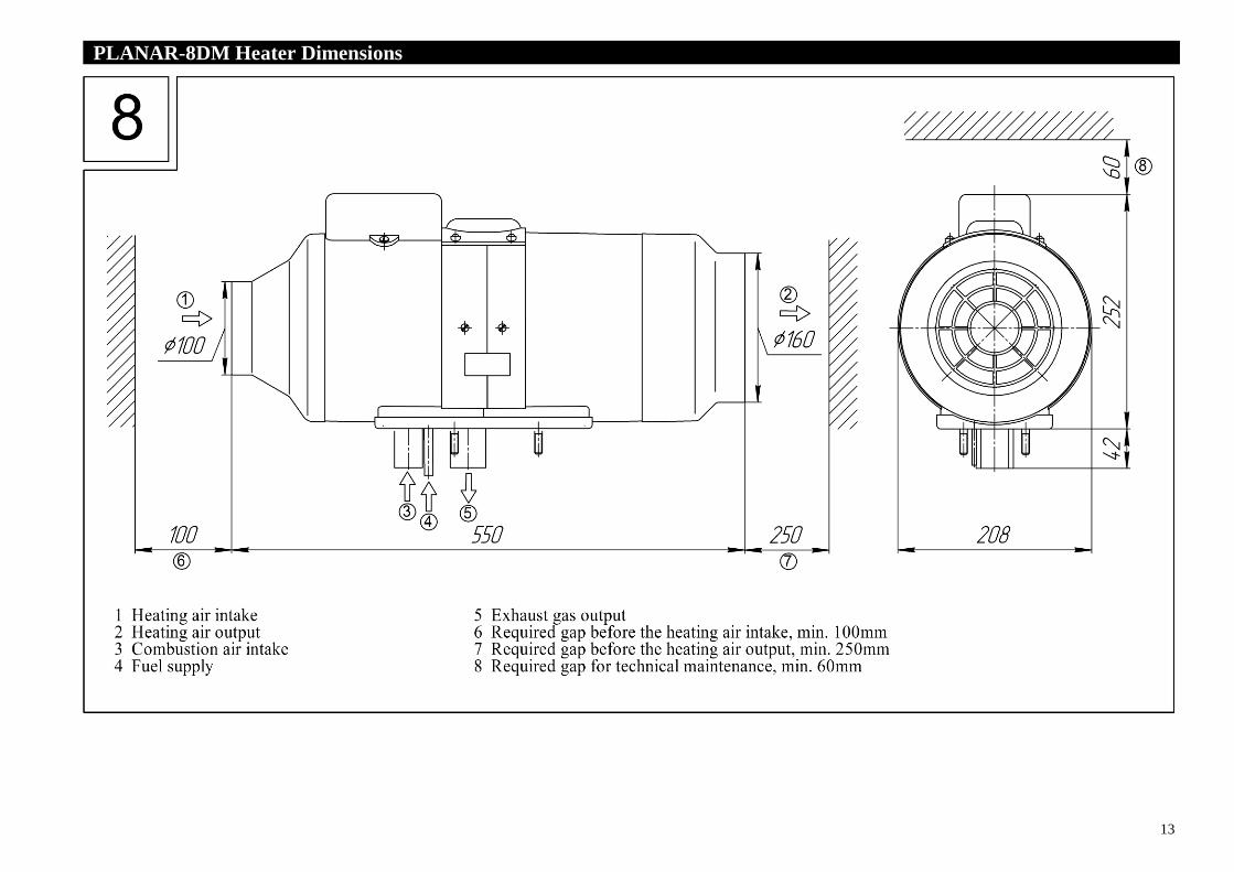
PLANAR-8DM Heater Dimensions 13
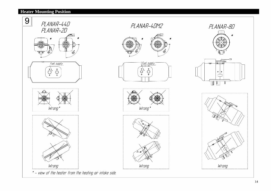
Heater Mounting Position 14
Heater Mounting holes 16
Checking the Heater after Installation 26
Recommendations 26
Electrical Wiring Diagram 27
3
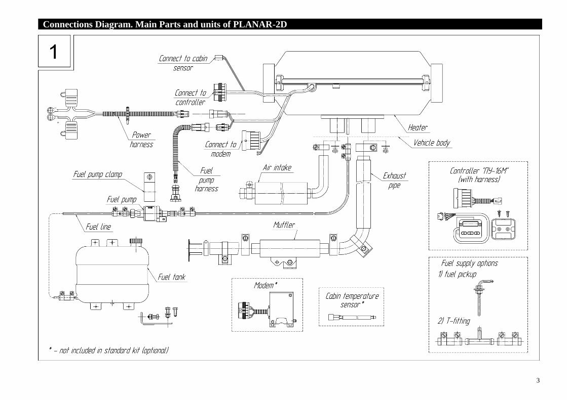
Connections Diagram. Main Parts and units of PLANAR-2D .
4
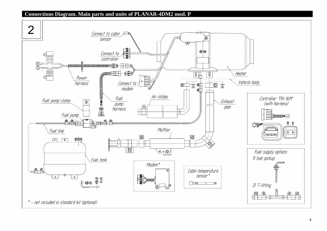
Connections Diagram. Main parts and units of PLANAR-4DM2 mod. P .

5
Connections Diagram. Main parts and units of PLANAR-44D mod. P .
6
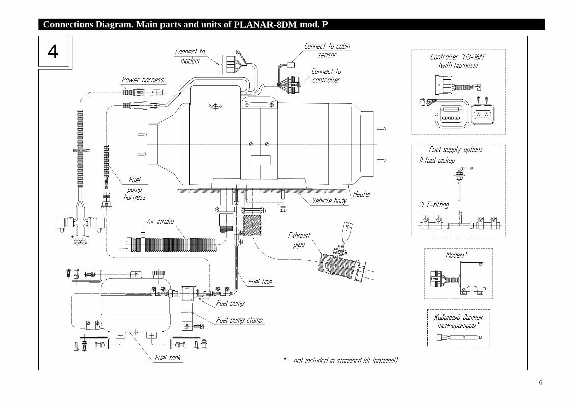
Connections Diagram. Main parts and units of PLANAR-8DM mod. P .
7
Technical Description
Introduction .
These Instructions are designed for organizations and
users engaged in the installation of PLANAR air heaters. The
document describes basic rules of installation of products in
heated areas, as well as performance testing of the product
after installation. These instructions are used in conjunction
with the Operation Manual.
If a fault occurs due to non-compliance with
the installation instructions and the
information they contain, the manufacturer
bears no responsibility therefore. The same
applies to the repair specialist who does not
have the necessary qualifications, or uses
non-original parts without obtaining the
permission of the manufacturer.
These installation instructions contain the necessary
information and advice on the installation of air heaters
PLANAR.
1 Application / modification .
Application of air heaters.
Air heaters are designed to heat the driver's cabin or
various other interior spaces of limited volume in vehicles
at ambient temperatures up to minus 45°C.
Modification
Heaters run on diesel fuel. Voltage designations in heater labeling:
«12» designed to operate with power supply voltage of 12V;
«24» designed to operate with power supply voltage of 24V.
Air heaters are available in different configurations and have
the following designations:
PLANAR-2D-12, PLANAR-2D-24
PLANAR-4DM2-12-Р-xxxх, PLANAR-4DM2-24-P-xxxх;
PLANAR-44D-12-GP-Р-xxxх, PLANAR-44D-24-GP-P-xxxх;
PLANAR-8DM-12-Р-xxxх, PLANAR-8DM-24-P-xxxх;
PLANAR-8DM – product designation;
12 or 24 – supply voltage;
P – modification of the heater (modification of control unit);
xxxх – digital designation of the configuration.
8
2 Safety Instructions .
The fuel line shall not be installed inside
the cabin of a vehicle.
Wiring (harnesses) shall not be installed
near the fuel line.
Vehicle, equipped with a heater, shall
have a fire extinguisher.
When electric welding is carried out on the vehicle, or
repair work is made on the heater, the heater shall be
disconnected from the battery.
When mounting and dismounting the heater, follow
safety regulations on electrical and fuel systems of the
vehicles.
The heater shall not be connected to the electric circuit
of the vehicle with its engine running and no battery
installed.
Installation of the heater and its component
parts shall be carried out by specialized
organizations approved by the manufacturer.
Installation of the heater shall be carried out
only by specialists in accordance with the
installation instructions/
Heater power shall not be disconnected until the end
of the purge cycle.
Power supply of the heater shall be provided for by a
battery only.
Connection/disconnection of the heater electrical
connectors shall not be made with power ON. After turning off
the heater, reconnection should be made at least after 5-10
seconds.
9
3 Installation .
Observe safety requirements during heater
installation.
3.1 Mounting Location
The heater can be mounted both inside and outside the
vehicle.
For outside mounting the heater should be installed in
an area protected from water and dirt. The heater should be
mounted in such a way that it is not exposed to water at
overcoming water obstacles by the vehicle.
Heater dimensions are shown in Figures 5-8.
3.2 Heater Installation
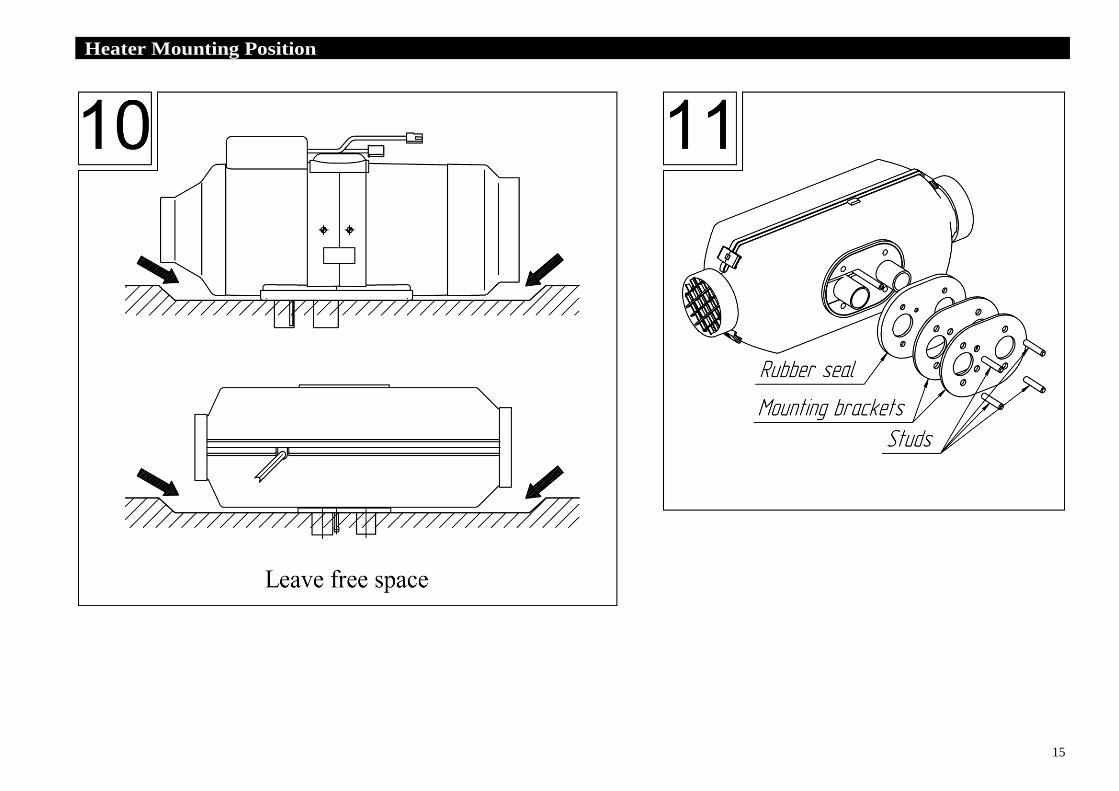
Mounting positions should be in accordance with
those shown in Fig.9-12. The intake of the heater should be
positioned in such a way that, under normal operating
conditions, exhaust gases of the engine or of the heater could
not be sucked into it.
During installation and operation of the heater, intake
and outlet of the heater should be protected against foreign
objects getting into them.
When installing the air ducts to the heater, they should
not have deformations, reducing the flow area of the duct.
The maximum length of the output duct should not exceed
5 meters in total.
When mounting the heater, care should be taken
to ensure that its housing does not have harmful
contact with projecting parts of the floor or other
parts of the cabin.
Installation of air ducts to the air heater
PLANAR-8DM is forbidden
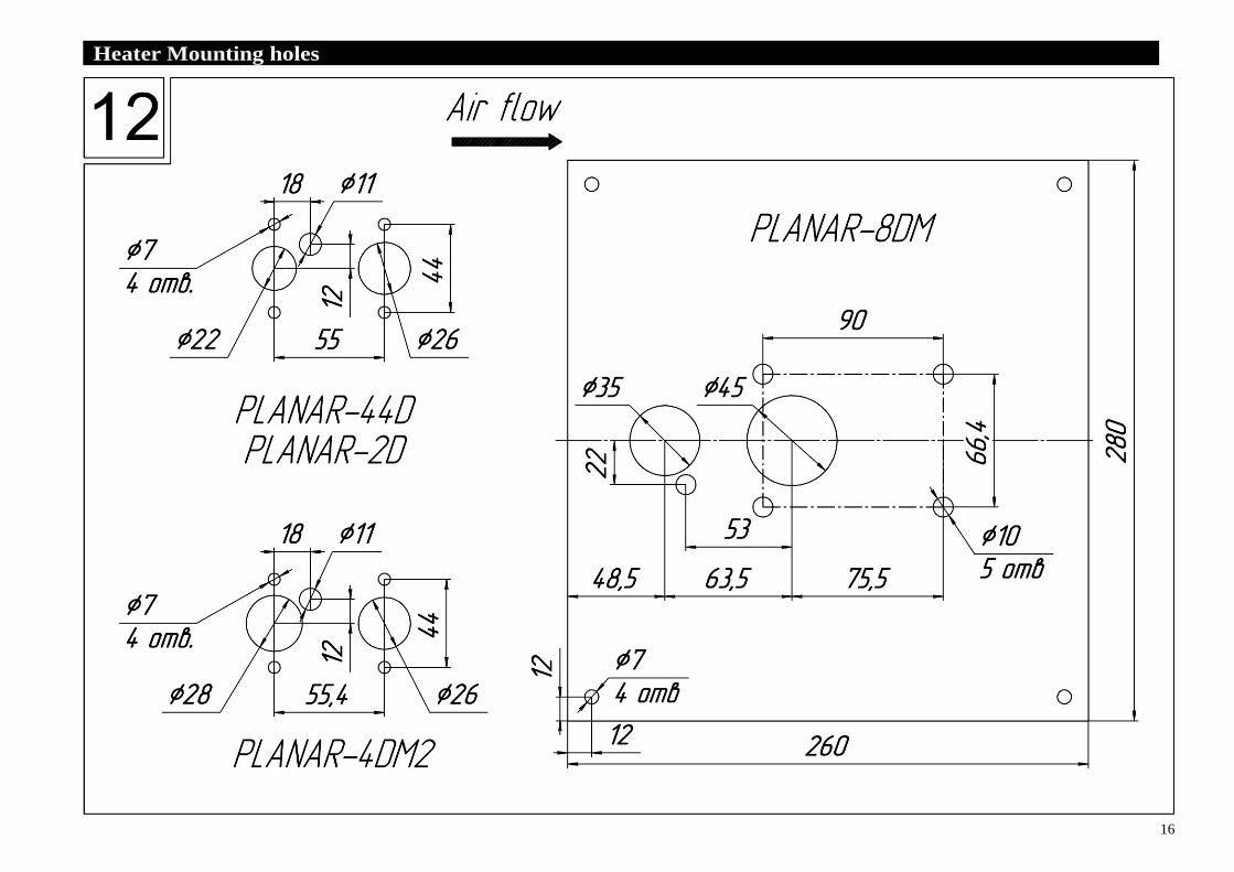
3.3 Mounting Holes.
For heaters PLANAR-2D, PLANAR-4DM2 and
PLANAR-44D, holes in the body of the vehicle should be
made as shown in Fig.12. Heater can be installed using
mounting brackets, see Fig.11 (in that case, longer studs should
be installed in the heater).
For heaters PLANAR-8DM, holes in the body of the
vehicle (with the thickness of the body (floor) of not more than
3mm) should be made as shown in Fig.12.
With the thickness of the vehicle body (floor) of more
than 3мм, installation of the heater requires the following:
1. To make a hole in the form of a rectangle with sides of
180 x 95 mm in the body of the vehicle;
2. To attach a mounting bracket to the heater (this bracket
can be made of steel sheet at least 2.5mm thick, see Fig.12); 3. To attach the exhaust pipe, air intake, and fuel line to
the heater and fasten the whole assembly to the body of
the vehicle

10
PLANAR-2D Heater Dimensions .
11
PLANAR-4DM2 Heater Dimensions .
12
PLANAR-44D Heater Dimensions .
13
PLANAR-8DM Heater Dimensions .
14
Heater Mounting Position .
15
Heater Mounting Position .
16
Heater Mounting holes .
17
3.4 Heating Air Supply
Heating air is taken from inside the room or from
outside.
Outside air should come from spaces protected from
rain, splashes and dirt, it should not be exposed to water
when the vehicle is crossing puddle, river, etc.
Hot air outlets should be placed in such a way
that air does not come in contact with parts
susceptible to damage by high temperature.
Do not crush or flatten hot air ducting. Duct
diameter should be greater than or equal to the
diameter of the output fitting of the heater.
Heating ducts should be manufactured only
from materials with heat resistance of at least
130°C.
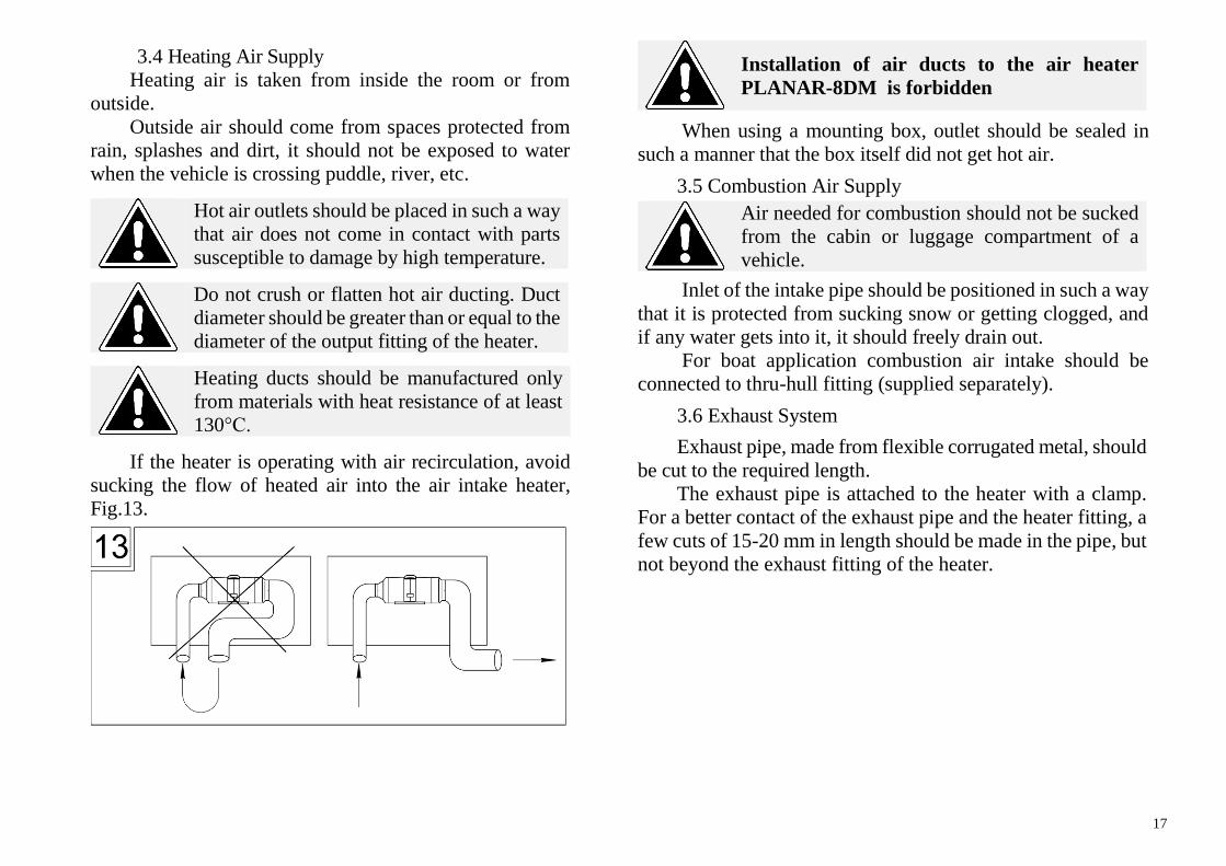
If the heater is operating with air recirculation, avoid
sucking the flow of heated air into the air intake heater,
Fig.13.
Installation of air ducts to the air heater
PLANAR-8DM is forbidden
When using a mounting box, outlet should be sealed in
such a manner that the box itself did not get hot air.
3.5 Combustion Air Supply
Air needed for combustion should not be sucked
from the cabin or luggage compartment of a
vehicle.
Inlet of the intake pipe should be positioned in such a way
that it is protected from sucking snow or getting clogged, and
if any water gets into it, it should freely drain out.
For boat application combustion air intake should be
connected to thru-hull fitting (supplied separately).
3.6 Exhaust System
Exhaust pipe, made from flexible corrugated metal, should
be cut to the required length.
The exhaust pipe is attached to the heater with a clamp.
For a better contact of the exhaust pipe and the heater fitting, a
few cuts of 15-20 mm in length should be made in the pipe, but
not beyond the exhaust fitting of the heater.
18
The end of the exhaust pipe should not touch
the rubber sealing of the heater.
When mounting the exhaust pipe, care should
be taken to eliminate penetration of exhaust
gases into the cabin or their sucking by the fan
through the radiator of the cab heater.
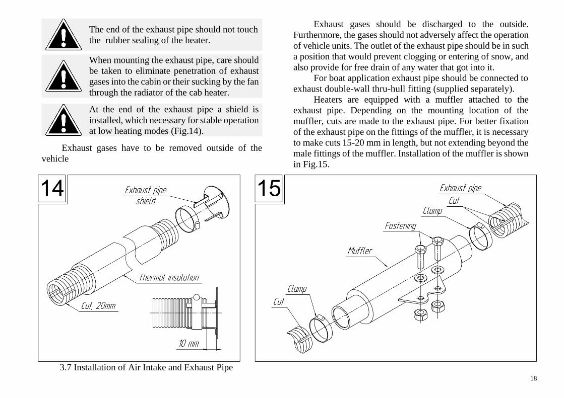
At the end of the exhaust pipe a shield is
installed, which necessary for stable operation
at low heating modes (Fig.14).
Exhaust gases have to be removed outside of the
vehicle
Exhaust gases should be discharged to the outside.
Furthermore, the gases should not adversely affect the operation
of vehicle units. The outlet of the exhaust pipe should be in such
a position that would prevent clogging or entering of snow, and
also provide for free drain of any water that got into it.
For boat application exhaust pipe should be connected to
exhaust double-wall thru-hull fitting (supplied separately).
Heaters are equipped with a muffler attached to the
exhaust pipe. Depending on the mounting location of the
muffler, cuts are made to the exhaust pipe. For better fixation
of the exhaust pipe on the fittings of the muffler, it is necessary
to make cuts 15-20 mm in length, but not extending beyond the
male fittings of the muffler. Installation of the muffler is shown
in Fig.15.
3.7 Installation of Air Intake and Exhaust Pipe
19
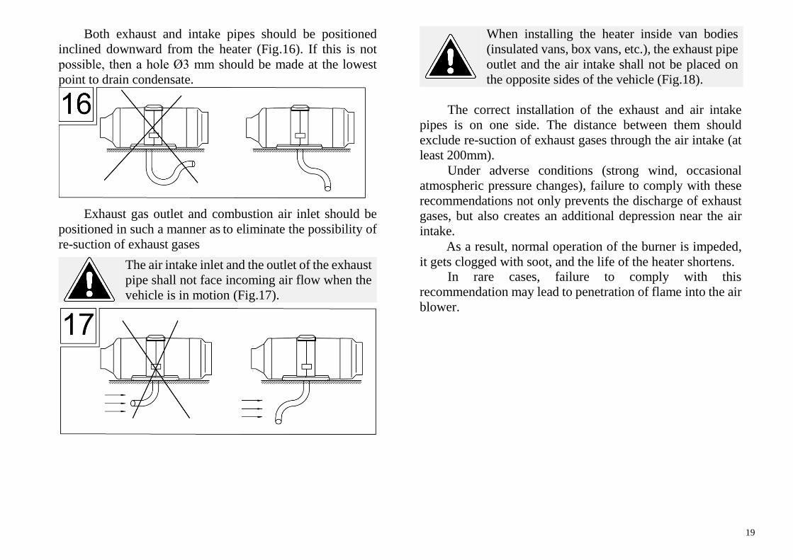
Both exhaust and intake pipes should be positioned
inclined downward from the heater (Fig.16). If this is not
possible, then a hole Ø3 mm should be made at the lowest
point to drain condensate.
Exhaust gas outlet and combustion air inlet should be
positioned in such a manner as to eliminate the possibility of
re-suction of exhaust gases
The air intake inlet and the outlet of the exhaust
pipe shall not face incoming air flow when the
vehicle is in motion (Fig.17).
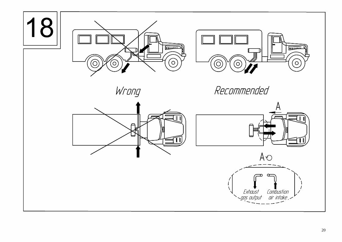
When installing the heater inside van bodies
(insulated vans, box vans, etc.), the exhaust pipe
outlet and the air intake shall not be placed on
the opposite sides of the vehicle (Fig.18).
The correct installation of the exhaust and air intake
pipes is on one side. The distance between them should
exclude re-suction of exhaust gases through the air intake (at
least 200mm).
Under adverse conditions (strong wind, occasional
atmospheric pressure changes), failure to comply with these
recommendations not only prevents the discharge of exhaust
gases, but also creates an additional depression near the air
intake.
As a result, normal operation of the burner is impeded,
it gets clogged with soot, and the life of the heater shortens. In rare cases, failure to comply with this
recommendation may lead to penetration of flame into the air
blower.
20
21
3.8 Insulation
At installation of an exhaust pipe it is necessary to
consider it's high temperature (to 500 °C, depending on
power) at operation.
Certain areas of the vehicle (electrical and other
systems) need extra protection from high temperatures. For
that reason, the exhaust pipe should be covered with
thermal insulation (Fig.14).
3.9 Fuel Supply.
It is forbidden to operate heaters on biofuel.
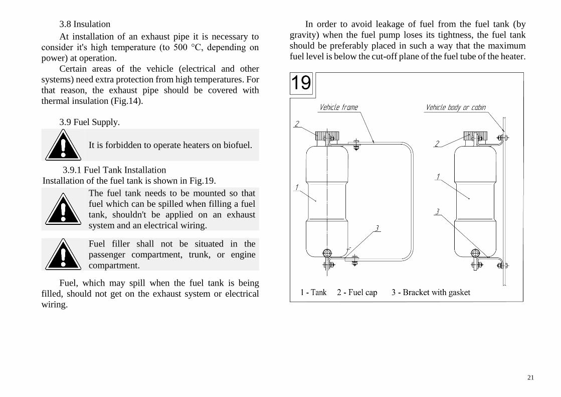
3.9.1 Fuel Tank Installation
Installation of the fuel tank is shown in Fig.19.
The fuel tank needs to be mounted so that
fuel which can be spilled when filling a fuel
tank, shouldn't be applied on an exhaust
system and an electrical wiring.
Fuel filler shall not be situated in the
passenger compartment, trunk, or engine
compartment.
Fuel, which may spill when the fuel tank is being
filled, should not get on the exhaust system or electrical
wiring.
In order to avoid leakage of fuel from the fuel tank (by
gravity) when the fuel pump loses its tightness, the fuel tank
should be preferably placed in such a way that the maximum
fuel level is below the cut-off plane of the fuel tube of the heater.
22
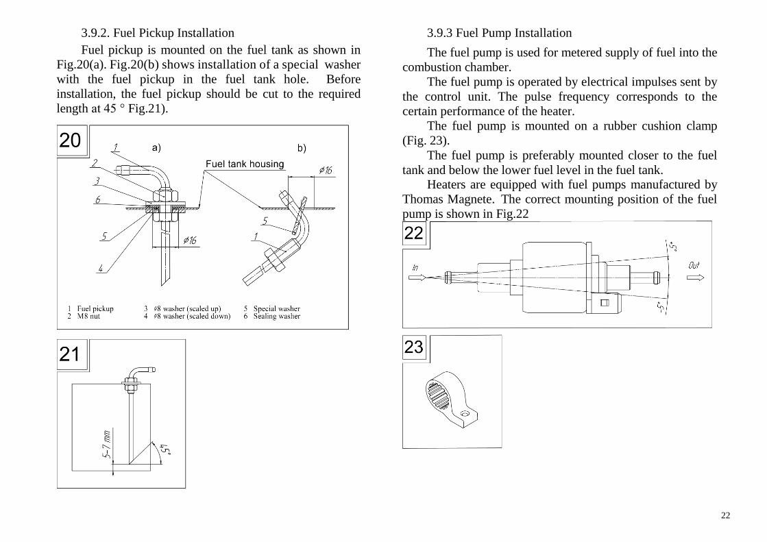
3.9.2. Fuel Pickup Installation
Fuel pickup is mounted on the fuel tank as shown in
Fig.20(a). Fig.20(b) shows installation of a special washer
with the fuel pickup in the fuel tank hole. Before
installation, the fuel pickup should be cut to the required
length at 45 ° Fig.21).
3.9.3 Fuel Pump Installation
The fuel pump is used for metered supply of fuel into the
combustion chamber.
The fuel pump is operated by electrical impulses sent by
the control unit. The pulse frequency corresponds to the
certain performance of the heater.
The fuel pump is mounted on a rubber cushion clamp
(Fig. 23).
The fuel pump is preferably mounted closer to the fuel
tank and below the lower fuel level in the fuel tank. Heaters are equipped with fuel pumps manufactured by
Thomas Magnete. The correct mounting position of the fuel
pump is shown in Fig.22
23
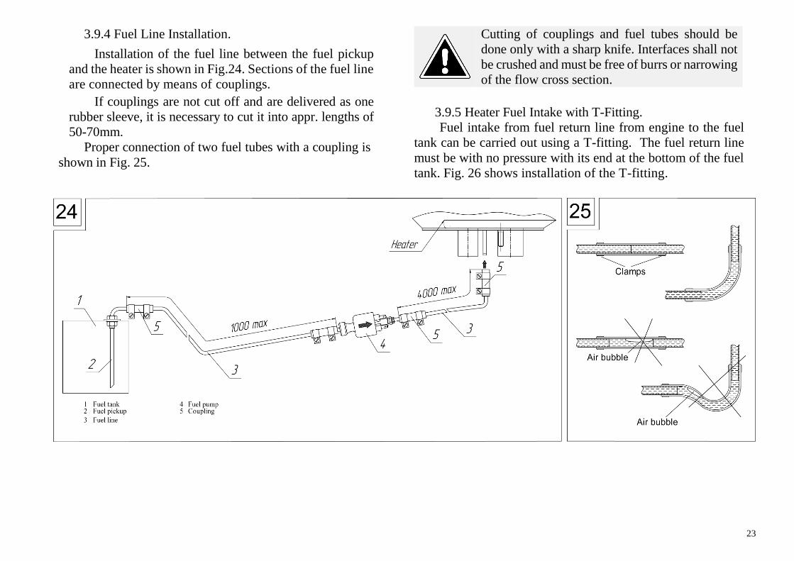
3.9.4 Fuel Line Installation.
Installation of the fuel line between the fuel pickup
and the heater is shown in Fig.24. Sections of the fuel line
are connected by means of couplings.
If couplings are not cut off and are delivered as one
rubber sleeve, it is necessary to cut it into appr. lengths of
50-70mm.
Proper connection of two fuel tubes with a coupling is
shown in Fig. 25.
Cutting of couplings and fuel tubes should be
done only with a sharp knife. Interfaces shall not
be crushed and must be free of burrs or narrowing
of the flow cross section.
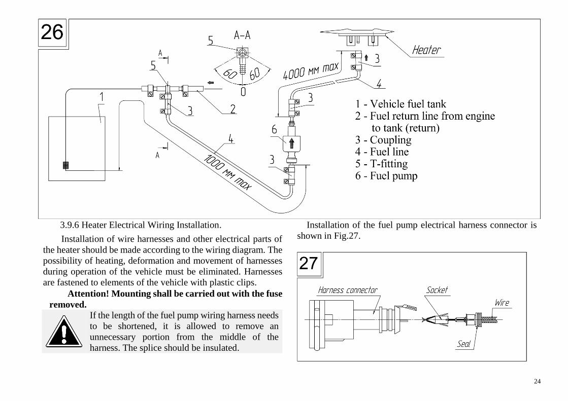
3.9.5 Heater Fuel Intake with T-Fitting.
Fuel intake from fuel return line from engine to the fuel
tank can be carried out using a T-fitting. The fuel return line
must be with no pressure with its end at the bottom of the fuel
tank. Fig. 26 shows installation of the T-fitting.
24
3.9.6 Heater Electrical Wiring Installation.
Installation of wire harnesses and other electrical parts of
the heater should be made according to the wiring diagram. The
possibility of heating, deformation and movement of harnesses
during operation of the vehicle must be eliminated. Harnesses
are fastened to elements of the vehicle with plastic clips.
Attention! Mounting shall be carried out with the fuse
removed.
If the length of the fuel pump wiring harness needs
to be shortened, it is allowed to remove an
unnecessary portion from the middle of the
harness. The splice should be insulated.
Installation of the fuel pump electrical harness connector is
shown in Fig.27.
25
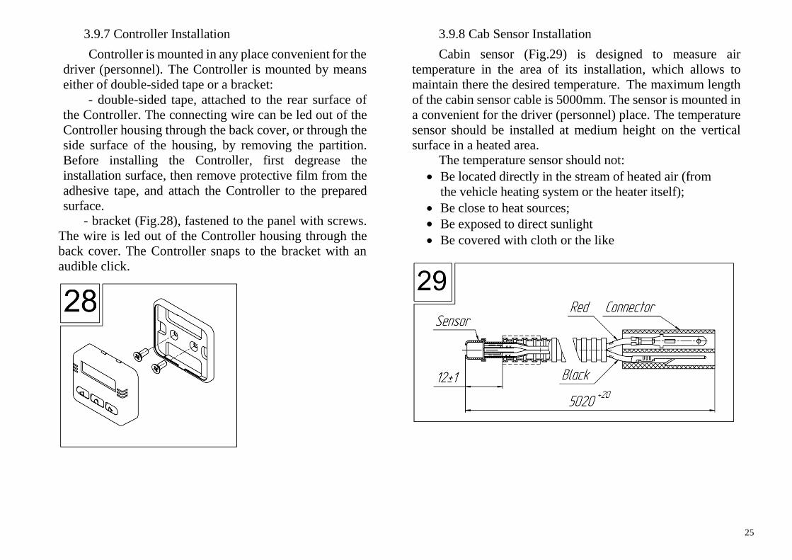
3.9.7 Controller Installation
Controller is mounted in any place convenient for the
driver (personnel). The Controller is mounted by means
either of double-sided tape or a bracket:
- double-sided tape, attached to the rear surface of
the Controller. The connecting wire can be led out of the
Controller housing through the back cover, or through the
side surface of the housing, by removing the partition.
Before installing the Controller, first degrease the
installation surface, then remove protective film from the
adhesive tape, and attach the Controller to the prepared
surface. - bracket (Fig.28), fastened to the panel with screws.
The wire is led out of the Controller housing through the
back cover. The Controller snaps to the bracket with an
audible click.
3.9.8 Cab Sensor Installation
Cabin sensor (Fig.29) is designed to measure air
temperature in the area of its installation, which allows to
maintain there the desired temperature. The maximum length
of the cabin sensor cable is 5000mm. The sensor is mounted in
a convenient for the driver (personnel) place. The temperature
sensor should be installed at medium height on the vertical
surface in a heated area. The temperature sensor should not:
Be located directly in the stream of heated air (from
the vehicle heating system or the heater itself);
Be close to heat sources;
Be exposed to direct sunlight
Be covered with cloth or the like
26
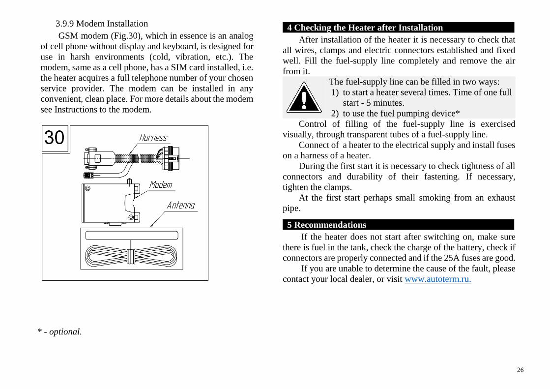
3.9.9 Modem Installation
GSM modem (Fig.30), which in essence is an analog
of cell phone without display and keyboard, is designed for
use in harsh environments (cold, vibration, etc.). The
modem, same as a cell phone, has a SIM card installed, i.e.
the heater acquires a full telephone number of your chosen
service provider. The modem can be installed in any
convenient, clean place. For more details about the modem
see Instructions to the modem.
4 Checking the Heater after Installation
After installation of the heater it is necessary to check that
all wires, clamps and electric connectors established and fixed
well. Fill the fuel-supply line completely and remove the air
from it.
The fuel-supply line can be filled in two ways:
1) to start a heater several times. Time of one full
start - 5 minutes.
2) to use the fuel pumping device*
Control of filling of the fuel-supply line is exercised
visually, through transparent tubes of a fuel-supply line.
Connect of a heater to the electrical supply and install fuses
on a harness of a heater.
During the first start it is necessary to check tightness of all
connectors and durability of their fastening. If necessary,
tighten the clamps.
At the first start perhaps small smoking from an exhaust
pipe.
5 Recommendations .
If the heater does not start after switching on, make sure
there is fuel in the tank, check the charge of the battery, check if
connectors are properly connected and if the 25A fuses are good.
If you are unable to determine the cause of the fault, please
contact your local dealer, or visit www.autoterm.ru.
* - optional.
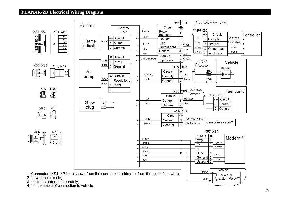
27
PLANAR-2D Electrical Wiring Diagram .
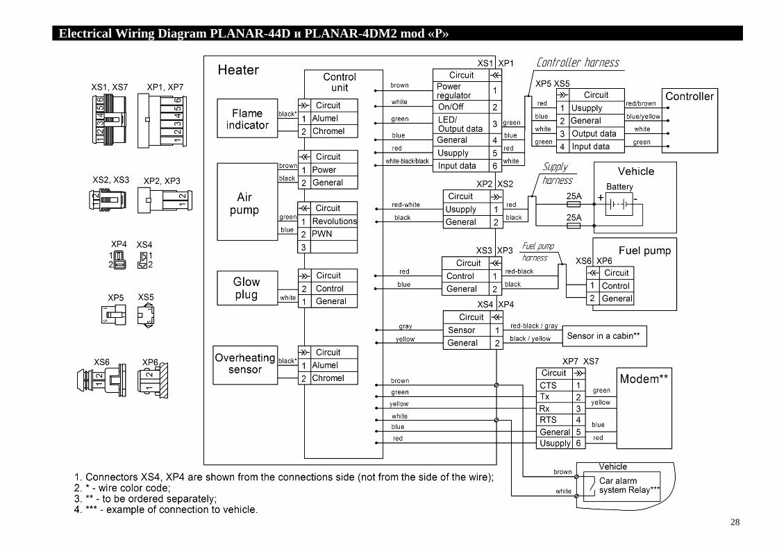
28
Electrical Wiring Diagram PLANAR-44D и PLANAR-4DM2 mod «Р» .
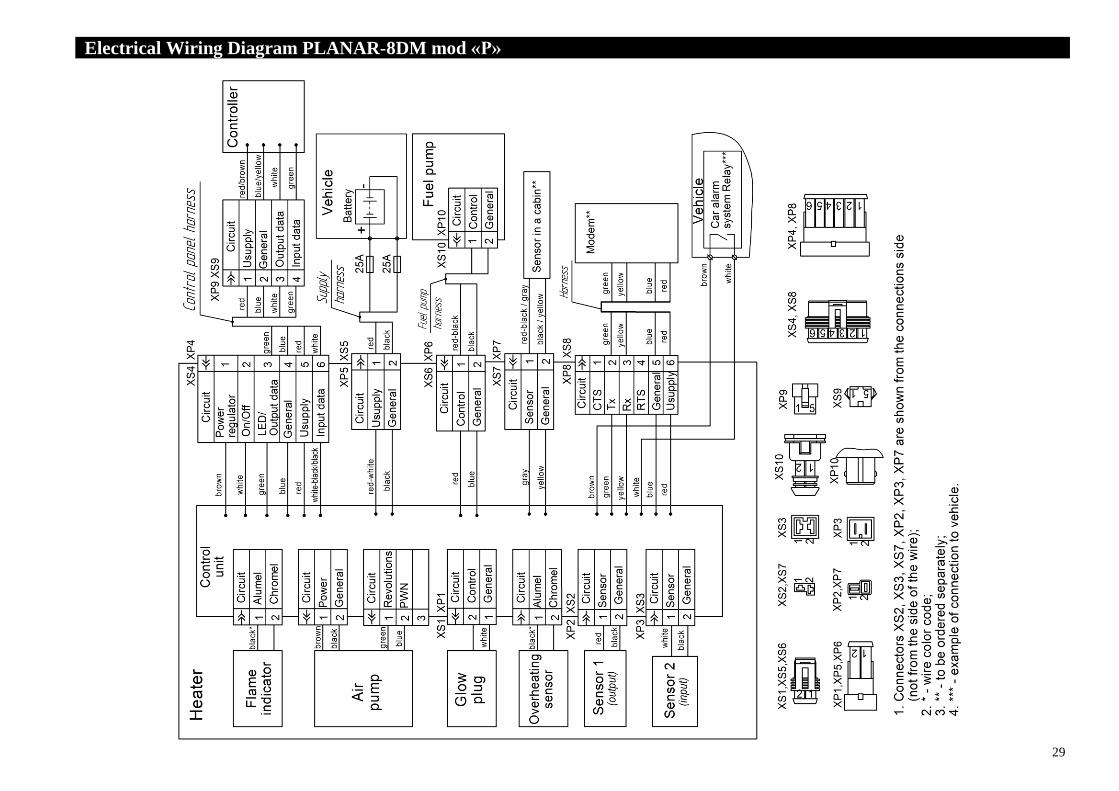
29
Electrical Wiring Diagram PLANAR-8DM mod «Р» .