new planar air-bearing microgravity simulator for
TRANSCRIPT

New Planar Air-bearing Microgravity Simulator for Verification of Space Robotics
Numerical Simulations and Control Algorithms
Tomasz Rybus1, Janusz Nicolau-Kukliński1, Karol Seweryn1, Tomasz Barciński2,
Monika Ciesielska1, Kamil Grassmann1, Jerzy Grygorczuk1, Michał Karczewski1,
Marek Kowalski1, Marcin Krzewski1, Tomasz Kuciński1, Jakub Lisowski1,
Rafał Przybyła1, Konrad Skup1, Tomasz Szewczyk1, Roman Wawrzaszek1
(1) Space Research Centre of the Polish Academy of Sciences
(2) Department of Control and Measurements, West Pomeranian
University of Technology
1 2 t h S y m p o s i u m o n A d v a n c e d S p a c e T e c h n o l o g i e s i n
R o b o t i c s a n d A u t o m a t i o n A S T R A 2 0 1 3
1 6 . 0 5 . 2 0 1 3

• Nearly one thousand of active satellites
orbits around Earth (April 2013).
• Malfunctions of satellites:
- failure of deployment mechanisms,
- failures of attitude control systems,
- premature fuel depletion.
• It is considered to use manipulator-
equipped autonomous satellites for on-
orbit servicing.
• Space debris (spent rocket stages, defunct satellites, small
fragments of satellites) pose real thread for active satellites and
human presence in orbit.
• Manipulator-equipped satellites could also be used for capturing
and removing from orbit specific large debris.
Applications of satell ite-
manipulator systems
Commercial satellite (conceptual illustration)

Applications of satell ite-
manipulator systems
Conceptual illustration of the satellite capture manoeuvre

Equation of satellite-manipulator dynamics:
Satell ite-manipulator
dynamics
Mass matrix
Coriolis matrix
Potential forces
Torques
Space manipulators
(free-floating)
� � � � � ����
���
� � 0
� � ��, �, … , ���
� � �� � � �, �� �� � � � � � ( 1 )
Ordinary manipulators
(fixed-base, working on Earth)
� � � �
� � � 0

In space:
- Dedicated demonstration missions,
- Tests of certain technologies on the ISS,
- Tests on-board the ISS.
On Earth:
- Suspension systems,
- Tests in the under-water environment,
- Tests on parabolic flights,
- Planar air-bearing microgravity-simulators.
Solutions for testing
space robots

Air-bearing microgravity
simulators• Free two-dimensional motion of the satellite-manipulator system.
• Satellite mock-up with attached robotic arm is mounted on air-
bearings.
• Air-bearings allow almost frictionless motion on the table surface,
thus simulating in two dimensions microgravity conditions.
• Possible applications:
- demonstration of control and trajectory planning algorithms,
- verification of numerical simulations of the satellite-manipulator
systems,
- tests of specific components of docking mechanisms ,
- tests preceding on-orbit demonstration missions.

Air-bearing microgravity
simulator in the SRC PAS

Air-bearing microgravity
simulator in the SRC PAS

Air-bearing microgravity
simulator in the SRC PAS
Parameter Value1 Base mass 12.9 kg
2Base moment
of inertia0.208 kg·m2
3 Link 1 mass 4.5 kg
4Link 1 moment
of inertia0.32 kg·m2
5 Link 1 length 0.62 m6 Link 2 mass 1.5 kg
7Link 2 moment
of inertia0.049 kg·m2
8 Link 2 length 0.6 m
9 (m1 + m2)/ m0 0.465
Geometrical and mass properties of the planar satellite-manipulator system

Planar air-bearings
• Generate a thin (5 ÷ 15 μm) film of pressurized air and slide on it.
• Based on a porous media technology.
• Pressurized air is supplied through a hole on a side of the bearing.
• Airflow is controlled across the entire bearing surface through
millions of holes in the porous carbon.
• Air pressure remains almost uniform across the whole surface.
• Immune to scratches and hard to clog.
Planar air-bearing

Mechanical design of
manipulator joint
• Each joint consists of a DC motor,
harmonic drive, two resilient
suspension plates and absolute optical
encoder.
• Five air-bearings are used - all support
points must be ideally coplanar.
• Each air bearing is mounted on a ball
stud.
• Resilient suspension plates are used
for compensation of possible vertical
misalignments between components of
the system.
Manipulator joint with resilientsuspension plates

Electronics and control
system
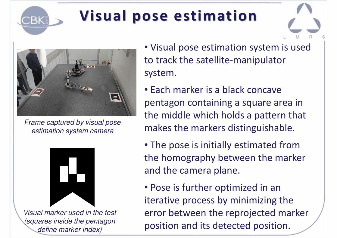
Visual pose estimation
• Visual pose estimation system is used
to track the satellite-manipulator
system.
• Each marker is a black concave
pentagon containing a square area in
the middle which holds a pattern that
makes the markers distinguishable.
• The pose is initially estimated from
the homography between the marker
and the camera plane.
• Pose is further optimized in an
iterative process by minimizing the
error between the reprojected marker
position and its detected position.
Frame captured by visual pose estimation system camera
Visual marker used in the test (squares inside the pentagon
define marker index)

We follow the General Jacobian Matrix (GJM) approach introduced by
Umetani and Yoshida (1989).
End-effector trajectory is given in the velocity space. Two equations
are solved simultaneously:
Inverse dynamics –
torque computation
�� � �� � ������
�������
� �
� �������
� � � � �� � � �, �� ��
Matrices H2 and H3 dependent not only on configuration of the
manipulator but also on the state of the servicing satellite.
For obtained trajectory of manipulator’s joints control torques Q are
computed:
( 2 )
( 3 )
( 4 )

Experimental results:
straight line trajectory
• Straight-line path of the end-effector (in the inertial reference
frame).
• Total reference end-effector translation: 0.6 m.
• Positions of manipulator joints are computed taking into account
free-floating nature of the satellite-manipulator system.
• Joint controllers are responsible for trajectory following in the
manipulator configuration space.
• We test the accuracy of the test-bed: no feedback from the end-
effector position is used.
• Experimental results are compared with reference trajectory and
results of numerical simulation.

Experimental results:
straight line trajectory
0 5 10 15 20-150
-100
-50
0
50
100
150
Join
t positio
n [
deg]
Time [s]
Joint 1
Joint 2
0 5 10 15 20-30
-25
-20
-15
-10
-5
0
5
10
Join
t velo
citie
s [
deg/s
]
Time [s]
Joint 1
Joint 2
Positions of manipulator joints for straight-line trajectory (data used by the control system in the experiment)
Velocities of manipulator joints for straight-line trajectory

Error of position of manipulator joints during the experiment (difference between the given trajectory
and data obtained from encoders)
0 5 10 15 20-0.1
-0.08
-0.06
-0.04
-0.02
0
0.02
0.04
0.06
0.08
0.1
Time [s]
Join
t positio
n e
rror
[deg]
Experimental results:
straight line trajectory

Air-bearing microgravity
simulator in the SRC PAS

Air-bearing microgravity
simulator in the SRC PAS

Air-bearing microgravity
simulator in the SRC PAS
Comparison between the given end-effector straight-line trajectory and end-effector position
measured during the experiment
0.7 0.8 0.9 1 1.1 1.2 1.3 1.41.7
1.8
1.9
2
2.1
2.2
2.3
2.4
x [m]
y [
m]
Experimental results
Reference trajectory
0 5 10 15 20-40
-20
0
20
40
60
80
100
Time [s]
Sate
llite
orienta
tion [
deg]
Experimental results
Numerical simulations
Comparison between the satellite orientation obtained from numerical simulations and orientation of manipulator base measured
during the experiment
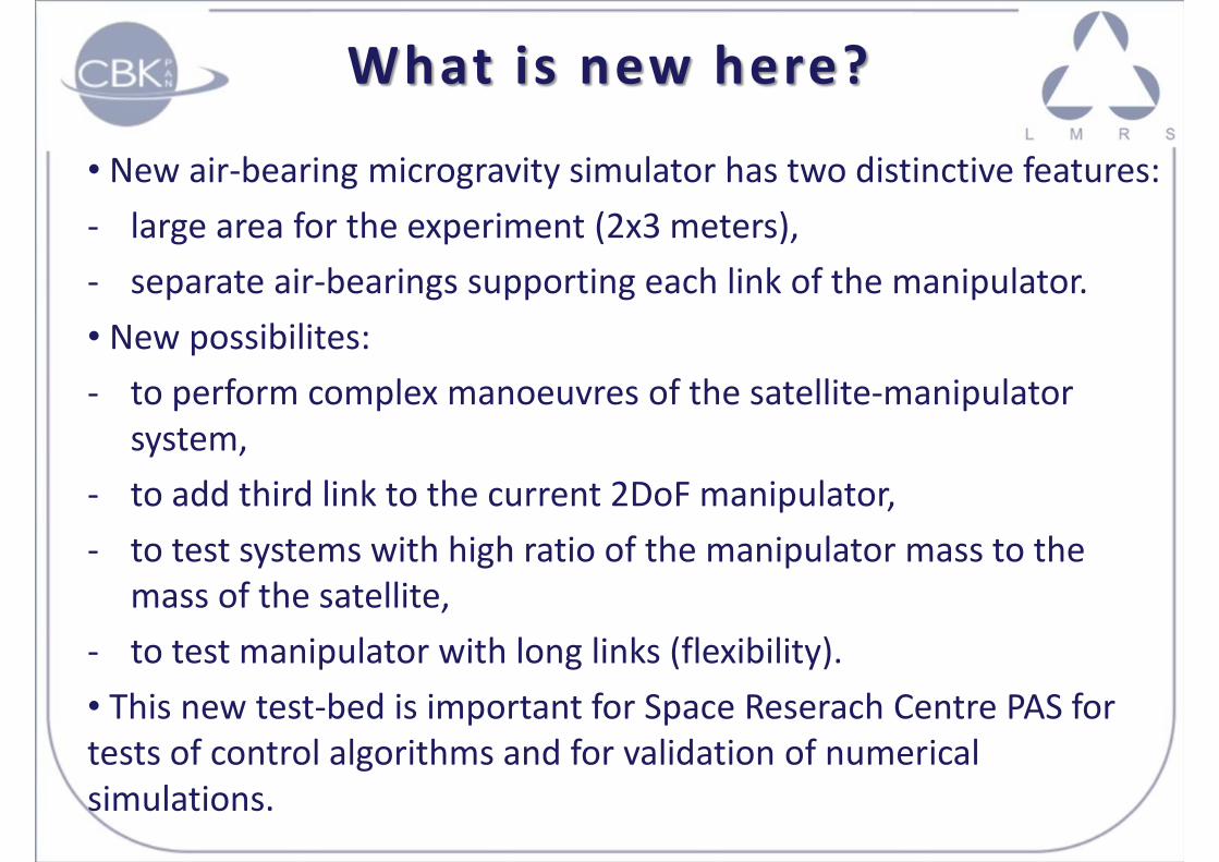
What is new here?
• New air-bearing microgravity simulator has two distinctive features:
- large area for the experiment (2x3 meters),
- separate air-bearings supporting each link of the manipulator.
• New possibilites:
- to perform complex manoeuvres of the satellite-manipulator
system,
- to add third link to the current 2DoF manipulator,
- to test systems with high ratio of the manipulator mass to the
mass of the satellite,
- to test manipulator with long links (flexibility).
• This new test-bed is important for Space Reserach Centre PAS for
tests of control algorithms and for validation of numerical
simulations.

Conclusions
• Tests of the satellite-manipulator systems are difficult on Earth.
• Air-bearing table is one of possible solutions, as it is simulating
microgravity conditions (in two dimensions) and is taking into
account free-floating nature of the satellite-manipulator system.
• New planar air-bearing microgravity simulator constructed recently
in the Space Research Centre PAS was presented and exemplary
experimental results were shown.
• In performed test no feedback from the end-effector position was
used (joint controllers were only responsible for trajectory following
in the manipulator configuration space).
• End-effector trajectory obtained from the experiment is very close
to the planned reference trajectory.

Thank you for
your attention!