piston pumps with reservoir piston pumps with reservoir for progressive and multiline systems for...
TRANSCRIPT
1-0107-2-US
Piston Pumps with Reservoir for progressive and multiline systemsfor grease up to NLGI grade 2
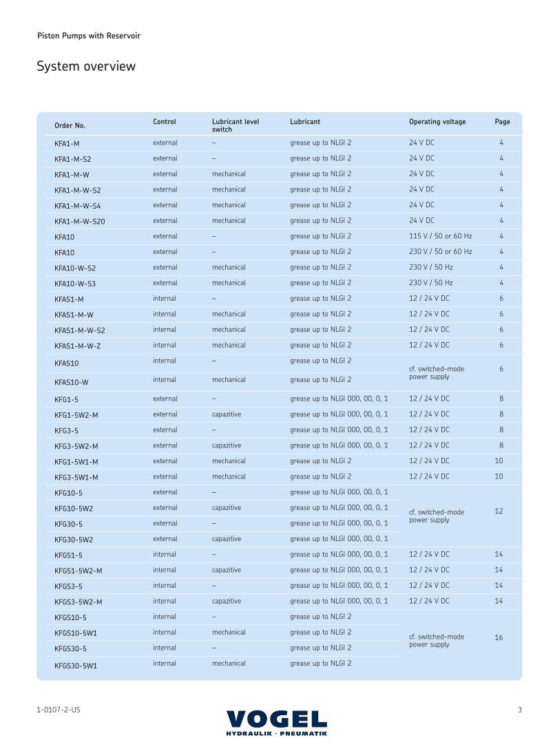
Because of their delivery rates and reservoir
capacities these grease pump units are
designed to supply small- and medium-size
systems. They come with 2 or 3 pump outlet
ports.
The possible operating voltages are 90 to
264 V AC, 47 to 440 Hz, or 12 or 24 V DC.
Safety elements like pressure-limiting valves,
overpressure indicators or rupture discs must
be provided for in order to protect the pump
unit from overloads.
Information on this point can also be found in
leaflet 1-0107-6-US, page 3 “Accessories”.
VPBM-6
VPBM-4
VPM-3-001
Diagram of a modular progressive system
with KFA10-W pump unit
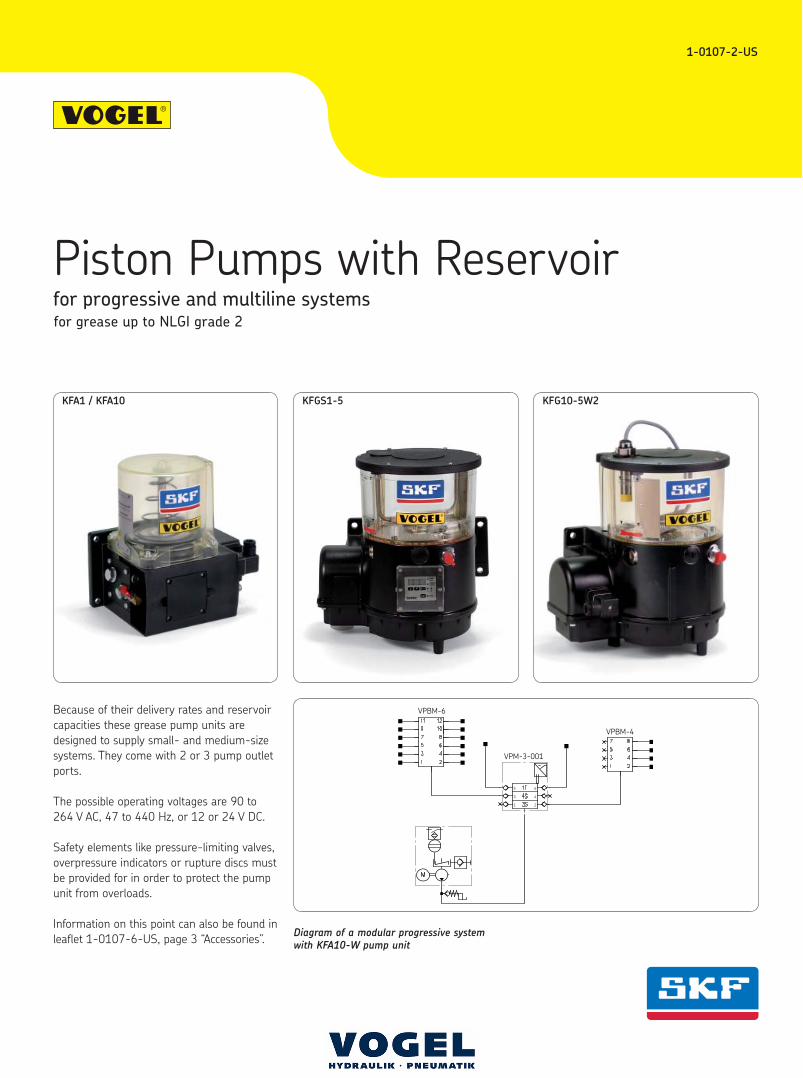
KFA1 / KFA10 KFGS1-5 KFG10-5W2
Im Folgenden finden Sie Informationen zu einem Teil unseres Leistungs-‐ und Serviceportfolios. Sollten Sie hierzu oder zu anderen Produkten Fragen haben, treten Sie jederzeit gern in Kontakt mit uns: Tel: 03573-‐ 14800 info@vogel-‐gruppe.de • Parker Store • Komponenten • 3D-‐Rohrbiege-‐Service • Wartung und Service • Hydraulik & Pneumatik • Aggregate-‐ und Anlagenbau • Mobiler Tag-‐ und Nacht vor-‐Ort-‐Service • Druckluft-‐Service • Schmiertechnik
Hauptsitz Senftenberg Laugkfeld 21, 01968 Senftenberg Tel: 03573 14 80-‐0 Bereitschaft: 0160 718 15 82 E-‐Mail: senftenberg@vogel-‐gruppe.de
Niederlassung Dresden Niedersedlitzer Str. 75 . 01257 Dresden Tel:0351 79 57 178 Bereitschaft: 0160 71 81 584 E-‐Mail: dresden@vogel-‐gruppe.de
Niederlassung Frankfurt/Oder Wildbahn 8, 15236 Frankfurt/Oder Tel: 0335 52 15 081 Bereitschaft: 0160 71 81 584 E-‐Mail: frankfurt@vogel-‐gruppe.de
Niederlassung Genshagen & Rohrbiegezentrum Seestr. 20, 14974 Genshagen Tel: 03378 87 90 67 Bereitschaft: 0171 22 65 930 E-‐Mail: genshagen@vogel-‐gruppe.de
Vertriebsgebiet Leipzig Tel.: +49 160 7181581 . E-‐Mail: leipzig@vogel-‐gruppe.de
Niederlassung Schöneiche August-‐Borsig-‐Ring 15, 15566 Schöneiche Tel: 030 64 93 581 Bereitschaft: 0160 71 81 590 E-‐Mail: schoeneiche@vogel-‐gruppe.de
Industrie-‐Hydraulik Vogel & Partner GmbH . Laugkfeld 21 . 01968 Senftenberg, Tel.: 03573 1480-‐0
info@vogel-‐gruppe.de . www.vogel-‐gruppe.de
Piston Pumps with Reservoir
31-0107-2-US
Order No.Control Lubricant level
switchLubricant Operating voltage Page
KFA1-M external – grease up to NLGI 2 24 V DC 4
KFA1-M-S2 external – grease up to NLGI 2 24 V DC 4
KFA1-M-W external mechanical grease up to NLGI 2 24 V DC 4
KFA1-M-W-S2 external mechanical grease up to NLGI 2 24 V DC 4
KFA1-M-W-S4 external mechanical grease up to NLGI 2 24 V DC 4
KFA1-M-W-S20 external mechanical grease up to NLGI 2 24 V DC 4
KFA10 external – grease up to NLGI 2 115 V / 50 or 60 Hz 4
KFA10 external – grease up to NLGI 2 230 V / 50 or 60 Hz 4
KFA10-W-S2 external mechanical grease up to NLGI 2 230 V / 50 Hz 4
KFA10-W-S3 external mechanical grease up to NLGI 2 230 V / 50 Hz 4
KFAS1-M internal – grease up to NLGI 2 12 / 24 V DC 6
KFAS1-M-W internal mechanical grease up to NLGI 2 12 / 24 V DC 6
KFAS1-M-W-S2 internal mechanical grease up to NLGI 2 12 / 24 V DC 6
KFAS1-M-W-Z internal mechanical grease up to NLGI 2 12 / 24 V DC 6
KFAS10 internal – grease up to NLGI 2
cf. switched-mode power supply
6
KFAS10-W internal mechanical grease up to NLGI 2
KFG1-5 external – grease up to NLGI 000, 00, 0, 1 12 / 24 V DC 8
KFG1-5W2-M external capazitive grease up to NLGI 000, 00, 0, 1 12 / 24 V DC 8
KFG3-5 external – grease up to NLGI 000, 00, 0, 1 12 / 24 V DC 8
KFG3-5W2-M external capazitive grease up to NLGI 000, 00, 0, 1 12 / 24 V DC 8
KFG1-5W1-M external mechanical grease up to NLGI 2 12 / 24 V DC 10
KFG3-5W1-M external mechanical grease up to NLGI 2 12 / 24 V DC 10
KFG10-5 external – grease up to NLGI 000, 00, 0, 1
cf. switched-mode power supply
12KFG10-5W2 external capazitive grease up to NLGI 000, 00, 0, 1
KFG30-5 external – grease up to NLGI 000, 00, 0, 1
KFG30-5W2 external capazitive grease up to NLGI 000, 00, 0, 1
KFGS1-5 internal – grease up to NLGI 000, 00, 0, 1 12 / 24 V DC 14
KFGS1-5W2-M internal capazitive grease up to NLGI 000, 00, 0, 1 12 / 24 V DC 14
KFGS3-5 internal – grease up to NLGI 000, 00, 0, 1 12 / 24 V DC 14
KFGS3-5W2-M internal capazitive grease up to NLGI 000, 00, 0, 1 12 / 24 V DC 14
KFGS10-5 internal – grease up to NLGI 2
cf. switched-mode power supply
16KFGS10-5W1 internal mechanical grease up to NLGI 2
KFGS30-5 internal – grease up to NLGI 2
KFGS30-5W1 internal mechanical grease up to NLGI 2
System overview
Piston Pumps with Reservoir
4 1-0107-2-US
The pump can be outfitted with a maximum of two pump elements.
Versions for various operating voltage are available.
Order No Voltage key Operating voltage
KFA1-M +924 24 V DC
KFA1-M-S2 +924 24 V DC
KFA10 +257 115 V / 50 Hz
KFA10 +263 230 V / 50 Hz
KFA10 +757 115 V / 60 Hz
KFA10 +763 230 V / 60 Hz
with lubricant level switch
KFA1-M-W +924 24 V DC
KFA1-M-W-S2 +924 24 V DC
KFA1-M-W-S4 +924 24 V DC
KFA1-M-W-S20 +924 24 V DC
KFA10-W-S2 +263 230 V / 50 Hz
KFA10-W-S3 +263 230 V / 50 Hz
Pressure-limiting valves
tube diam. Order No. Opening Connection
pressure [bar] thread
6 161-210-042 120
6 161-210-032 200
6 161-210-016 300
8 161-210-041 120 M14×1.5
8 161-210-031 200
10 161-210-040 120
10 161-210-030 200
Notice:
The installation’s ambient surroundings and cable connections have a
decisive influence on the unit’s electromagnetic compatibility.
During the installation it is therefore necessary to assure the EMC of
the entire system.
Applicable protection measures for operation:
– “Protective Extra Low Voltage” (PELV)
Standards: IEC 60204-1; HD 384.4.41 (DIN VDE 0100-410)
– The unit has to be disconnected for insulation and voltage
tests to EN 602041:1992.
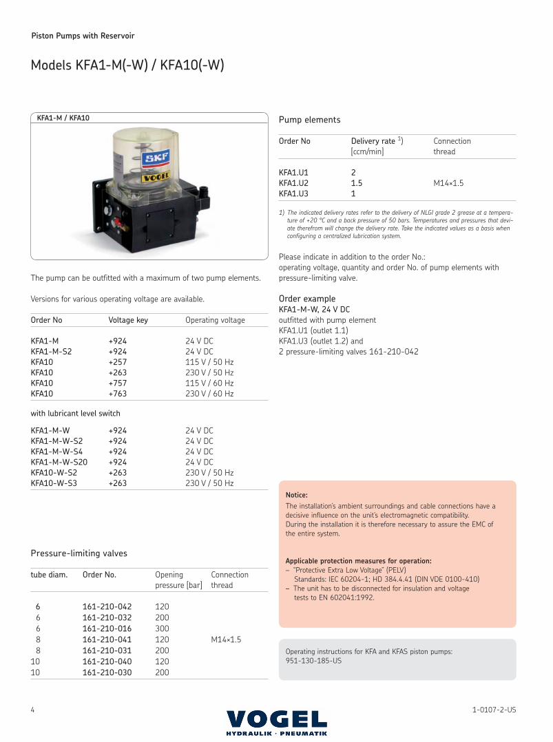
KFA1-M / KFA10
Models KFA1-M(-W) / KFA10(-W)
Operating instructions for KFA and KFAS piston pumps:
951-130-185-US
Pump elements
Order No Delivery rate 1) Connection
[ccm/min] thread
KFA1.U1 2
KFA1.U2 1.5 M14×1.5
KFA1.U3 1
1) The indicated delivery rates refer to the delivery of NLGI grade 2 grease at a tempera-
ture of +20 °C and a back pressure of 50 bars. Temperatures and pressures that devi-
ate therefrom will change the delivery rate. Take the indicated values as a basis when
configuring a centralized lubrication system.
Please indicate in addition to the order No.:
operating voltage, quantity and order No. of pump elements with
pressure-limiting valve.
Order example
KFA1-M-W, 24 V DC
outfitted with pump element
KFA1.U1 (outlet 1.1)
KFA1.U3 (outlet 1.2) and
2 pressure-limiting valves 161-210-042
Piston Pumps with Reservoir
51-0107-2-US
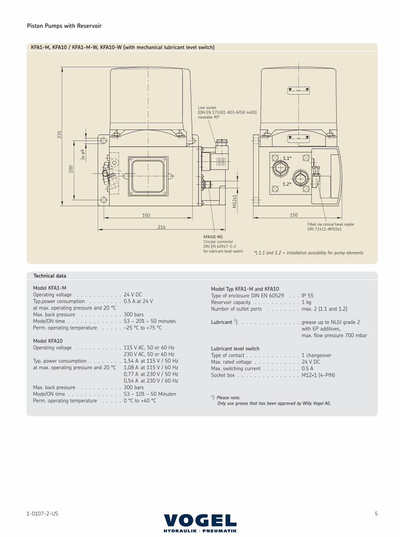
KFA1-M, KFA10 / KFA1-M-W, KFA10-W (with mechanical lubricant level switch)
*) 1.1 and 1.2 = installation possibility for pump elements
Technical data
Model KFA1-M
Operating voltage . . . . . . . . . . . 24 V DC
Typ.power consumption . . . . . . . . 0.5 A at 24 V
at max. operating pressure and 20 °C
Max. back pressure . . . . . . . . . . 300 bars
Mode/ON time . . . . . . . . . . . . . S3 – 20% – 50 minutes
Perm. operating temperature . . . . . –25 °C to +75 °C
Model KFA10
Operating voltage . . . . . . . . . . . 115 V AC, 50 or 60 Hz
230 V AC, 50 or 60 Hz
Typ. power consumption . . . . . . . . 1,54 A at 115 V / 50 Hz
at max. operating pressure and 20 °C 1,08 A at 115 V / 60 Hz
0,77 A at 230 V / 50 Hz
0,54 A at 230 V / 60 Hz
Max. back pressure . . . . . . . . . . 300 bars
Mode/ON time . . . . . . . . . . . . . S3 – 10% – 50 Minuten
Perm. operating temperature . . . . . 0 °C to +40 °C
Model Typ KFA1-M and KFA10
Type of enclosure DIN EN 60529 . . . IP 55
Reservoir capacity . . . . . . . . . . . 1 kg
Number of outlet ports . . . . . . . . max. 2 (1.1 and 1.2)
Lubricant 2) . . . . . . . . . . . . . . grease up to NLGI grade 2
with EP additives,
max. flow pressure 700 mbar
Lubricant level switch
Type of contact . . . . . . . . . . . . . 1 changeover
Max. rated voltage . . . . . . . . . . . 24 V DC
Max. switching current . . . . . . . . . 0.5 A
Socket box . . . . . . . . . . . . . . . M12×1 (4-PIN)
2) Please note:
Only use grease that has been approved by Willy Vogel AG.
Piston Pumps with Reservoir
6 1-0107-2-US
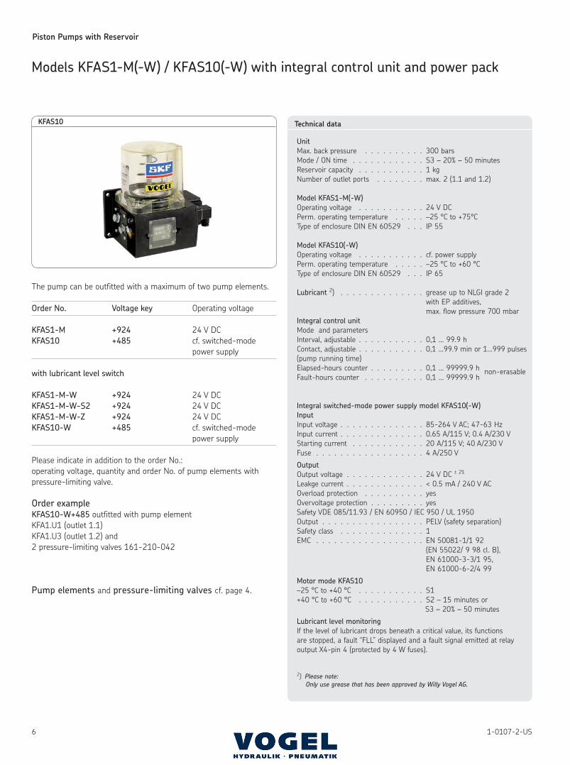
Models KFAS1-M(-W) / KFAS10(-W) with integral control unit and power pack
The pump can be outfitted with a maximum of two pump elements.
Order No. Voltage key Operating voltage
KFAS1-M +924 24 V DC
KFAS10 +485 cf. switched-mode
power supply
with lubricant level switch
KFAS1-M-W +924 24 V DC
KFAS1-M-W-S2 +924 24 V DC
KFAS1-M-W-Z +924 24 V DC
KFAS10-W +485 cf. switched-mode
power supply
Please indicate in addition to the order No.:
operating voltage, quantity and order No. of pump elements with
pressure-limiting valve.
Order example
KFAS10-W+485 outfitted with pump element
KFA1.U1 (outlet 1.1)
KFA1.U3 (outlet 1.2) and
2 pressure-limiting valves 161-210-042
Pump elements and pressure-limiting valves cf. page 4.
KFAS10 Technical data
Unit
Max. back pressure . . . . . . . . . . 300 bars
Mode / ON time . . . . . . . . . . . . S3 – 20% – 50 minutes
Reservoir capacity . . . . . . . . . . . 1 kg
Number of outlet ports . . . . . . . . max. 2 (1.1 and 1.2)
Model KFAS1-M(-W)
Operating voltage . . . . . . . . . . . 24 V DC
Perm. operating temperature . . . . . –25 °C to +75°C
Type of enclosure DIN EN 60529 . . . IP 55
Model KFAS10(-W)
Operating voltage . . . . . . . . . . . cf. power supply
Perm. operating temperature . . . . . –25 °C to +60 °C
Type of enclosure DIN EN 60529 . . . IP 65
Lubricant 2) . . . . . . . . . . . . . . grease up to NLGI grade 2
with EP additives,
max. flow pressure 700 mbar
Integral control unit
Mode and parameters
Interval, adjustable . . . . . . . . . . . 0,1 … 99.9 h
Contact, adjustable . . . . . . . . . . . 0,1 …99.9 min or 1…999 pulses
(pump running time)
Elapsed-hours counter . . . . . . . . . 0,1 … 99999.9 h non-erasable
Fault-hours counter . . . . . . . . . . 0,1 … 99999.9 h
Integral switched-mode power supply model KFAS10(-W)
Input
Input voltage . . . . . . . . . . . . . . 85-264 V AC; 47-63 Hz
Input current . . . . . . . . . . . . . . 0.65 A/115 V; 0.4 A/230 V
Starting current . . . . . . . . . . . . 20 A/115 V; 40 A/230 V
Fuse . . . . . . . . . . . . . . . . . . 4 A/250 V
Output
Output voltage . . . . . . . . . . . . . 24 V DC ± 2%
Leakge current . . . . . . . . . . . . . < 0.5 mA / 240 V AC
Overload protection . . . . . . . . . . yes
Overvoltage protection . . . . . . . . . yes
Safety VDE 085/11.93 / EN 60950 / IEC 950 / UL 1950
Output . . . . . . . . . . . . . . . . . PELV (safety separation)
Safety class . . . . . . . . . . . . . . 1
EMC . . . . . . . . . . . . . . . . . . EN 50081-1/1 92
(EN 55022/ 9 98 cl. B),
EN 61000-3-3/1 95,
EN 61000-6-2/4 99
Motor mode KFAS10
–25 °C to +40 °C . . . . . . . . . . . S1
+40 °C to +60 °C . . . . . . . . . . . S2 – 15 minutes or
S3 – 20% – 50 minutes
Lubricant level monitoring
If the level of lubricant drops beneath a critical value, its functions
are stopped, a fault “FLL” displayed and a fault signal emitted at relay
output X4-pin 4 (protected by 4 W fuses).
2) Please note:
Only use grease that has been approved by Willy Vogel AG.
Piston Pumps with Reservoir
71-0107-2-US
Notice:
The installation’s ambient surroundings and cable connections have a
decisive influence on the unit’s electromagnetic compatibility.
During the installation it is therefore necessary to assure the EMC of
the entire system.
Applicable protection measures for operation:
– “Protective Extra Low Voltage” (PELV)
Standards: IEC 60204-1; HD 384.4.41 (DIN VDE 0100-410)
– The unit has to be disconnected for insulation and voltage
tests to EN 602041:1992.
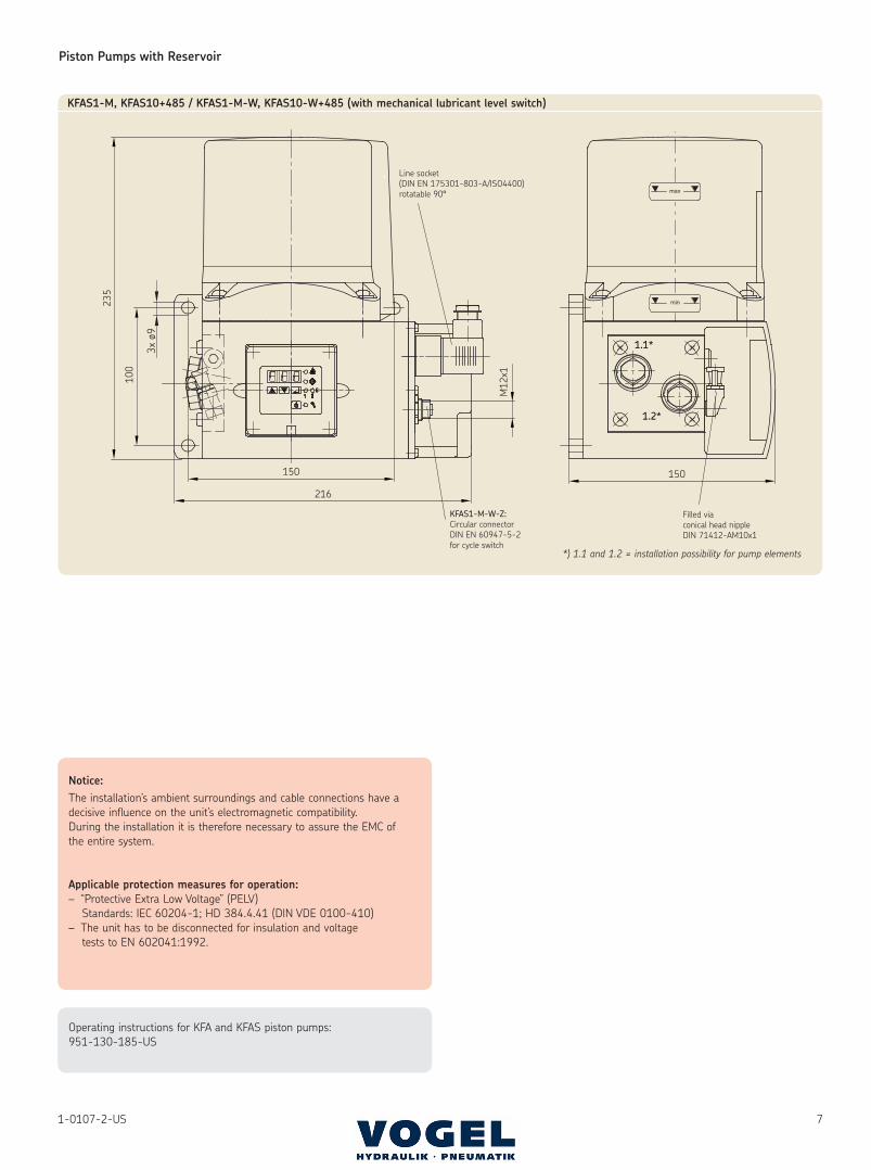
216
150
100
235
M12
x1
150
1.1*
1.2*
KFAS1-M, KFAS10+485 / KFAS1-M-W, KFAS10-W+485 (with mechanical lubricant level switch)
Operating instructions for KFA and KFAS piston pumps:
951-130-185-US
*) 1.1 and 1.2 = installation possibility for pump elements
Piston Pumps with Reservoir
8 1-0107-2-US
with lubricant level switch Reservoir capacity
Order No. Order No. [kg]
KFG1-5 KFG1-5W2-M 2
KFG3-5 KFG3-5W2-M 6
Please indicate in addition to the order No.:
operating voltage, quantity and order No. of pump elements
(max. 3) with pressure-limiting valve.
Order example
KFG1-5W2-M, 24 V DC outfitted with pump element
KFG1.U1 (outlet 1.1)
KFG1.U2 (outlet 1.2)
KFG1.U3 (outlet 1.3) and
3 pressure-limiting valves 161-210-040
Pump elements
Order No. Delivery rate 1) Connection
[ccm/min] thread
KFG1.U0 5
KFG1.U1 2.5
KFG1.U2 1.8 M14×1.5
KFG1.U3 1.3
KFG1.U4 0.8
1) The indicated delivery rates refer to the delivery of NLGI grade 2 grease at a tem-perature of +20 °C and a back pressure of 50 bars. Temperatures and pressures that deviate therefrom will change the delivery rate. Take the indicated values as a basis when configuring a centralized lubrication system.
Pressure-limiting valves cf. page 4.
Technical data
Motor
Operating Voltage . . . . . . . . . . . 12 V DC / 24 V DC
Fuse . . . . . . . . . . . . . . . . . . 6 A / 4 A
Unit
Max. back pressure . . . . . . . . . . 300 bars
Perm. operating temperature . . . . . –25 °C to +75 °C
Type of enclosure DIN EN 60529 . . . IP 55
Reservoir capacity . . . . . . . . . . . 2 or 6 kg
Reservoir material . . . . . . . . . . . PA6i
Number of outlet ports . . . . . . . . max. 3 (1.1, 1.2 and 1.3)(If less than 3 outlet ports are needed, screw plugs are used in place of pump elements.)
Lubricant 2) . . . . . . . . . . . . . . grease up to
NLGI grades 000, 00, 0 and 1
compatible with plastic,
NBR elastomers,
copper and copper alloys.
Max. flow pressure 700 mbar
Lubricant level switch W2 (capazitive)
Function:
Switch opens when lubricant drops to critical level.
Fault also signaled in the event of a wire break.
Operating voltage . . . . . . . . . . . 10 to 30 V DC
Switching frequency . . . . . . . . . . 100 Hz
Continuous current . . . . . . . . . . . ≤ 200 mA
Natural current consumption . . . . . . 6 to 12 mA
Voltage drop . . . . . . . . . . . . . . ≤ 1,8 at Icontinuous
EC directives . . . . . . . . . . . . . . EN 60947-5-2
2) Please note:Only use grease that has been approved by Willy Vogel AG.
Notice:
The installation’s ambient surroundings and cable connections have a
decisive influence on the unit’s electromagnetic compatibility.
During the installation it is therefore necessary to assure the EMC of
the entire system.
Applicable protection measures for operation:
– “Protective Extra Low Voltage” (PELV)
Standards: IEC 60204-1; HD 384.4.41 (DIN VDE 0100-410)
– The unit has to be disconnected for insulation and voltage
tests to EN 602041:1992.
Operating instructions for KFG and KFGS piston pumps:
951-130-184-US
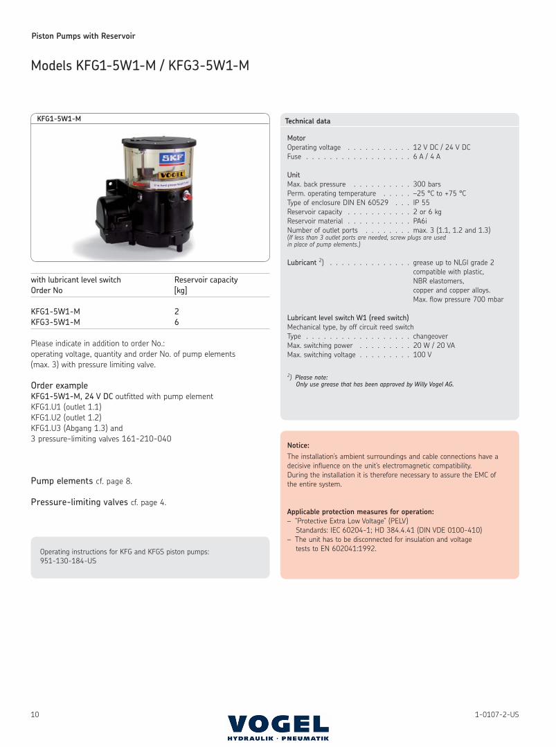
KFG1-5
Models KFG1-5(W2-M) / KFG3-5(W2-M)
Piston Pumps with Reservoir
91-0107-2-US
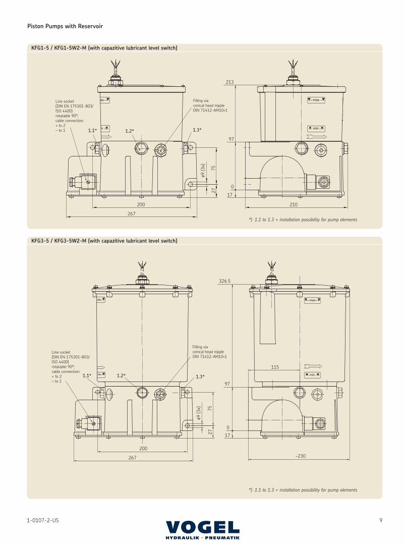
KFG1-5 / KFG1-5W2-M (with capazitive lubricant level switch)
*) 1.1 to 1.3 = installation possibility for pump elements
KFG3-5 / KFG3-5W2-M (with capazitive lubricant level switch)
*) 1.1 to 1.3 = installation possibility for pump elements
115
Piston Pumps with Reservoir
10 1-0107-2-US
with lubricant level switch Reservoir capacity
Order No [kg]
KFG1-5W1-M 2
KFG3-5W1-M 6
Please indicate in addition to order No.:
operating voltage, quantity and order No. of pump elements
(max. 3) with pressure limiting valve.
Order example
KFG1-5W1-M, 24 V DC outfitted with pump element
KFG1.U1 (outlet 1.1)
KFG1.U2 (outlet 1.2)
KFG1.U3 (Abgang 1.3) and
3 pressure-limiting valves 161-210-040
Pump elements cf. page 8.
Pressure-limiting valves cf. page 4.
Technical data
Motor
Operating voltage . . . . . . . . . . . 12 V DC / 24 V DC
Fuse . . . . . . . . . . . . . . . . . . 6 A / 4 A
Unit
Max. back pressure . . . . . . . . . . 300 bars
Perm. operating temperature . . . . . –25 °C to +75 °C
Type of enclosure DIN EN 60529 . . . IP 55
Reservoir capacity . . . . . . . . . . . 2 or 6 kg
Reservoir material . . . . . . . . . . . PA6i
Number of outlet ports . . . . . . . . max. 3 (1.1, 1.2 and 1.3)(If less than 3 outlet ports are needed, screw plugs are used in place of pump elements.)
Lubricant 2) . . . . . . . . . . . . . . grease up to NLGI grade 2
compatible with plastic,
NBR elastomers,
copper and copper alloys.
Max. flow pressure 700 mbar
Lubricant level switch W1 (reed switch)
Mechanical type, by off circuit reed switch
Type . . . . . . . . . . . . . . . . . . changeover
Max. switching power . . . . . . . . . 20 W / 20 VA
Max. switching voltage . . . . . . . . . 100 V
2) Please note:Only use grease that has been approved by Willy Vogel AG.
Notice:
The installation’s ambient surroundings and cable connections have a
decisive influence on the unit’s electromagnetic compatibility.
During the installation it is therefore necessary to assure the EMC of
the entire system.
Applicable protection measures for operation:
– “Protective Extra Low Voltage” (PELV)
Standards: IEC 60204-1; HD 384.4.41 (DIN VDE 0100-410)
– The unit has to be disconnected for insulation and voltage
tests to EN 602041:1992.Operating instructions for KFG and KFGS piston pumps:
951-130-184-US
KFG1-5W1-M
Models KFG1-5W1-M / KFG3-5W1-M
Piston Pumps with Reservoir
111-0107-2-US
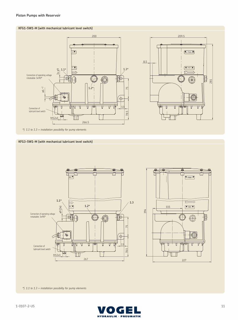
KFG1-5W1-M (with mechanical lubricant level switch)
*) 1.1 to 1.3 = installation possibility for pump elements
1.1*
1.2*1.3
KFG3-5W1-M (with mechanical lubricant level switch)
*) 1.1 to 1.3 = installation possibility for pump elements
Piston Pumps with Reservoir
12 1-0107-2-US
with lubricant level switch Reservoir capacity
Order No Order No. [kg]
KFG10-5 KFG10-5W2 2
KFG30-5 KFG30-5W2 6
Please indicate in addition to order No.:
operating voltage, quantity and order No. of pump elements
(max. 3) with pressure limiting valve.
Order example
KFG10-5W2 outfitted with pump element
KFG1.U1 (outlet 1.1)
KFG1.U2 (outlet 1.2)
KFG1.U3 (outlet 1.3) and
3 pressure-limiting valves 161-210-042
Pump elements cf. page 8.
Pressure-limiting valves cf. page 4.
Technical data
Motor
Operating voltage . . . . . . . . . . . cf. switched-mode power supply
Fuse . . . . . . . . . . . . . . . . . . 6 A / 4 A
Unit
Max. back pressure . . . . . . . . . . 300 bars
Perm. operating temperature . . . . . –25 °C to +75 °C
Type of enclosure DIN EN 60529 . . . IP 55
Reservoir capacity . . . . . . . . . . . 2 or 6 kg
Reservoir material . . . . . . . . . . . PA6i
Number of outlet ports . . . . . . . . max. 3 (1.1, 1.2 and 1.3)(If less than 3 outlet ports are needed, screw plugs are used in place of pump elements.)
Lubricant 2) . . . . . . . . . . . . . . grease up to
NLGI grades 000, 00, 0 and 1
compatible with plastic,
NBR elastomers,
copper and copper alloys.
Max. flow pressure 700 mbar
Integral switched-mode power supply
Input
Input voltage . . . . . . . . . . . . . . . . . . . . . . 90-264 V AC; 47-440 Hz
Input current . . . . . . . . . . . . . . . . . . . . . 1.5 A/115 V; 0.9 A/230 V
Strating current . . . . . . . . . . . . . . . . . . . 40 A/115 V; 20 A/230 V
Fuse . . . . . . . . . . . . . . . . . . . . . . . . . . . . 4 A/250 V
Output
Output voltage . . . . . . . . . . . . . . . . . . . . 24 V DC ± 2%
Leakge current . . . . . . . . . . . . . . . . . . . . < 0.5 mA / 240 V AC
Overload protection . . . . . . . . . . . . . . . . yes
Überspannungsschutz . . . . . . . . . . . . . . yes
Safety VDE 085/11.93 / EN 60950 / IEC 950 / UL 1950
Output . . . . . . . . . . . . . . . . . . . . . . . . . . PELV (safety separation)
Safety class . . . . . . . . . . . . . . . . . . . . . . 1
EMC . . . . . . . . . . . . . . . . . . . . . . . . . . . . EN 55022 cl. B,
IEC 1000-4-2, 3, 4, 5
IEC 1000-4-2, 3
Motor mode
–25 °C to +40 °C . . . . . . . . . . . . . . . . . . S1
+40 °C to +60 °C . . . . . . . . . . . . . . . . . . S2 – 15 minutes or
S3 – 20% – 30 minutes
Notice:
The installation’s ambient surroundings and cable connections have a
decisive influence on the unit’s electromagnetic compatibility.
During the installation it is therefore necessary to assure the EMC
of the entire system.
Operating instructions for KFG and KFGS piston pumps:
951-130-184-US
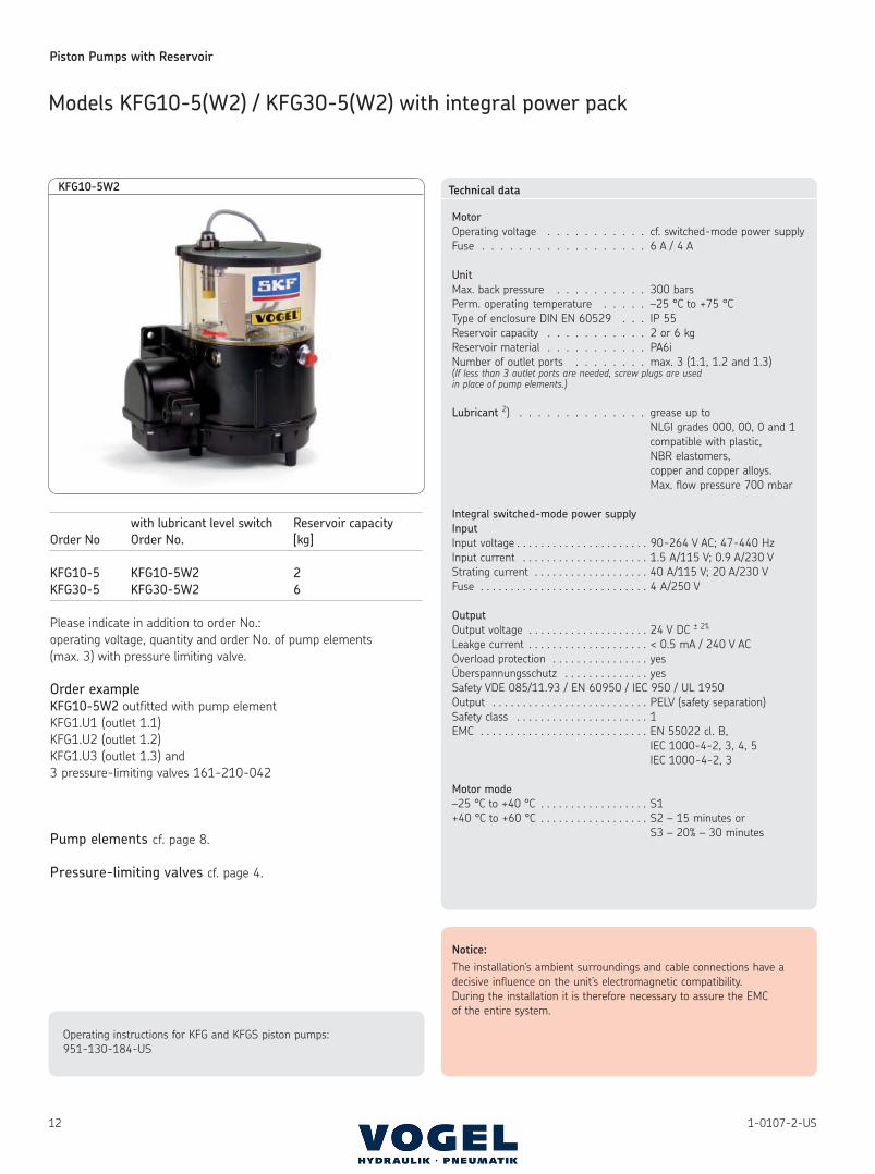
KFG10-5W2
Models KFG10-5(W2) / KFG30-5(W2) with integral power pack
Piston Pumps with Reservoir
131-0107-2-US
115
210
281
ø9 (3
x) 75
200
267
1.1*
1.2*1.3*
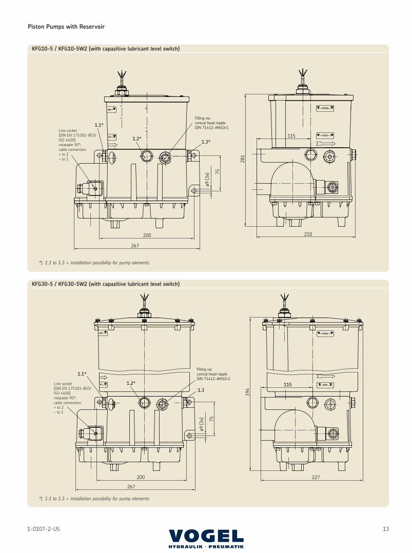
Filling viaconical head nippleDIN 71412-AM10×1
KFG10-5 / KFG10-5W2 (with capazitive lubricant level switch)
*) 1.1 to 1.3 = installation possibility for pump elements
200
267
ø9 (3
x) 75
227
394
115
1.1*
1.2*1.3
Filling viaconical head nippleDIN 71412-AM10×1
KFG30-5 / KFG30-5W2 (with capazitive lubricant level switch)
*) 1.1 to 1.3 = installation possibility for pump elements
Piston Pumps with Reservoir
14 1-0107-2-US
Models KFGS1-5(W2-M) / KFGS3-5(W2-M) with integral control unit
with lubricant level switch Reservoir capacity
Order No. Order No. [kg]
KFGS1-5 KFGS1-5W2-M 2
KFGS3-5 KFGS3-5W2-M 6
Please indicate in addition to order No.:
operating voltage, quantity and order No. of pump elements
(max. 3) with pressure limiting valve.
Order example
KFGS1-5W2-M, 24 V DC outfitted with pump element
KFG1.U1 (outlet 1.1)
KFG1.U2 (outlet 1.2)
KFG1.U3 (outlet 1.3) and
3 pressure-limiting valves 161-210-040
Pump elements cf. page 8.
Pressure-limiting valves cf. page 4.
Cable harness, order No. 997-000-630
not included in scope of delivery and has to be ordered separately.
Technical data
Motor
Operating voltage . . . . . . . . . . . 12 V DC / 24 V DC
Fuse . . . . . . . . . . . . . . . . . . 6 A / 4 A
Unit
Max. back pressure . . . . . . . . . . 300 bars
Perm. operating temperature . . . . . –25 °C to +75 °C
Type of enclosure DIN EN 60529 . . . IP 55
Reservoir capacity . . . . . . . . . . . 2 or 6 kg
Reservoir material . . . . . . . . . . . PA6i
Anzahl der Auslässe. . . . . . . . . . . max. 3 (1.1, 1.2 and 1.3)(If less than 3 outlet ports are needed, screw plugs are used in place of pump elements.)
Lubricant 2) . . . . . . . . . . . . . . grease up to
NLGI grades 000, 00, 0 and 1
compatible with plastics,
NBR elastomers,
copper and copper alloys.
Max. flow pressure 700 mbar
Integral control unit
Mode of operation and parameters
Interval time, adjustable . . . . . . . . 0,1 … 99,9 h
Contact time, adustable . . . . . . . . 0,1 … 99,9 min or 1 … 999 pulse
(pump running time)
Elapsed time counter . . . . . . . . . . 0,1 … 99999,9 h not erasable
Error hour counter . . . . . . . . . . . 0,1 … 99999,9 h
Monitoring, adjustable
with cycle switch (CS) or without monitoring (OFF)
Basic setting factory made: timer
Pump running time . . . . . . . . . . tCO = 4 min
Interval time . . . . . . . . . . . . . tPA = 1 h
Monitoring . . . . . . . . . . . . . . COP = OFF
Notice:
The installation’s ambient surroundings and cable connections have a
decisive influence on the unit’s electromagnetic compatibility.
During the installation it is therefore necessary to assure the EMC of
the entire system.
Applicable protection measures for operation:
– “Protective Extra Low Voltage” (PELV)
Standards: IEC 60204-1; HD 384.4.41 (DIN VDE 0100-410)
– The unit has to be disconnected for insulation and voltage
tests to EN 602041:1992.Operating instructions for KFG and KFGS piston pumps:
951-130-184-US
KFGS1-5
Piston Pumps with Reservoir
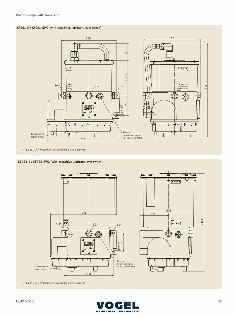
151-0107-2-US
200
6312
7.5
75
ø9 (3
x)
267
346
210
1.1*1.2* 1.3*
Filling viaconical head nippleDIN 71412-AM10x1
Connection forcable harness
*) 1.1 to 1.3 = installation possibility for pump elements
~266
75ø9
(3x)
200
115~226
~394
1.1* 1.2* 1.3*
Connection forcable harness
Filling viaconical head nippleDIN 71412-AM10x1
KFGS3-5 / KFGS3-5W2 (with capazitive lubricant level switch)
*) 1.1 to 1.3 = installation possibility for pump elements
KFGS1-5 / KFGS1-5W2 (with capazitive lubricant level switch)
Piston Pumps with Reservoir
16 1-0107-2-US
with lubricant level switch Reservoir capacity
Order No. Order No. [kg]
KFGS10-5 KFGS10-5W1 2
KFGS30-5 KFGS30-5W1 6
Please indicate in addition to order No.:
operating voltage, quantity and order No. of pump elements
(max. 3) with pressure limiting valve.
Order example
KFGS10-5W1 outfitted with pump element
KFG1.U1 (outlet 1.1)
KFG1.U2 (outlet 1.2)
KFG1.U3 (outlet 1.3) and
3 pressure-limiting valves 161-210-042
Pump elements cf. page 8.
Pressure-limiting valves cf. page 4.
Technical data
Motor
Operating voltage . . . . . . . . . . . cf. switched-mode power supply
Fuse . . . . . . . . . . . . . . . . . . 6 A / 4 A
Unit
Max. back pressure . . . . . . . . . . 300 bars
Perm. operating temperature . . . . . –25 °C to +60 °C
Type of enclosure DIN EN 60529 . . . IP 55
Reservoir capacity . . . . . . . . . . . 2 or 6 kg
Reservoir material . . . . . . . . . . . PA6i
Number of outlets . . . . . . . . . . . max. 3 (1.1, 1.2 and 1.3)(If less than 3 outlet ports are needed, screw plugs are used in place of pump elements.)
Lubricant 2) . . . . . . . . . . . . . . grease up to NLGI grade 2
compatible with plastic,
NBR elastomers,
copper and copper alloys.
Max. flow pressure 700 mbar
Lubricant level monitoring W1
Type . . . . . . . . . . . . . . . . . . reed contact
Function: The unit switches off when the critical lubricant level is
reached, a fault is shown on the display (FLL).
Integral control unit
Mode of operation and parameters
Interval, adjustable . . . . . . . . . . . 0.1 … 99.9 h
Contact, adjustable . . . . . . . . . . 0.1 … 99.9 min or 1 … 999 pulses
(pump running time)
Elapsed-hours counter . . . . . . . . . 0.1 … 99999.9 h not erasable
Fault-hours counter . . . . . . . . . . 0.1 … 99999.9 h
Monitoring, adjustable
with cycle switch (CS) or without monitoring (OFF)
Basic factory setting: timer mode
Pump running time . . . . . . . . . . tCO = 4 min
Interval time . . . . . . . . . . . . . . tPA = 1 h
Monitoring . . . . . . . . . . . . . . . COP = OFF
Integral switched-mode power supply – cf. page 12
Notice:
The installation’s ambient surroundings and cable connections have a
decisive influence on the unit’s electromagnetic compatibility.
During the installation it is therefore necessary to assure the EMC
of the entire system.
Operating instructions for KFG and KFGS piston pumps:
951-130-184-US
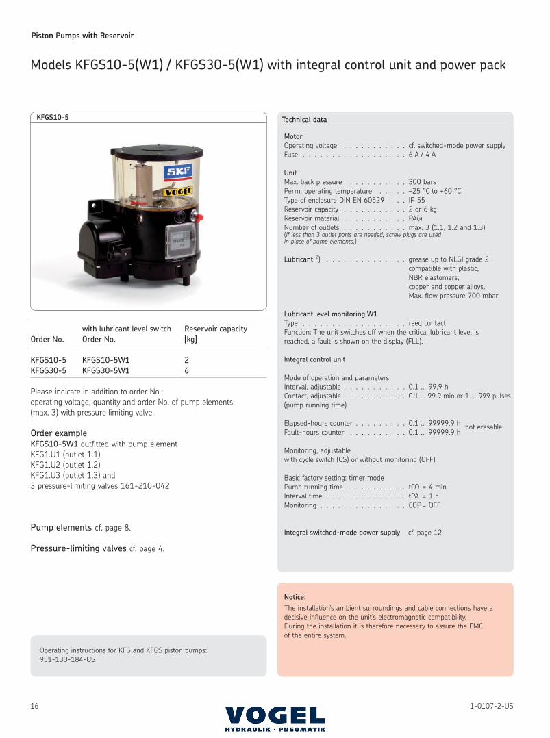
KFGS10-5
Models KFGS10-5(W1) / KFGS30-5(W1) with integral control unit and power pack
Piston Pumps with Reservoir
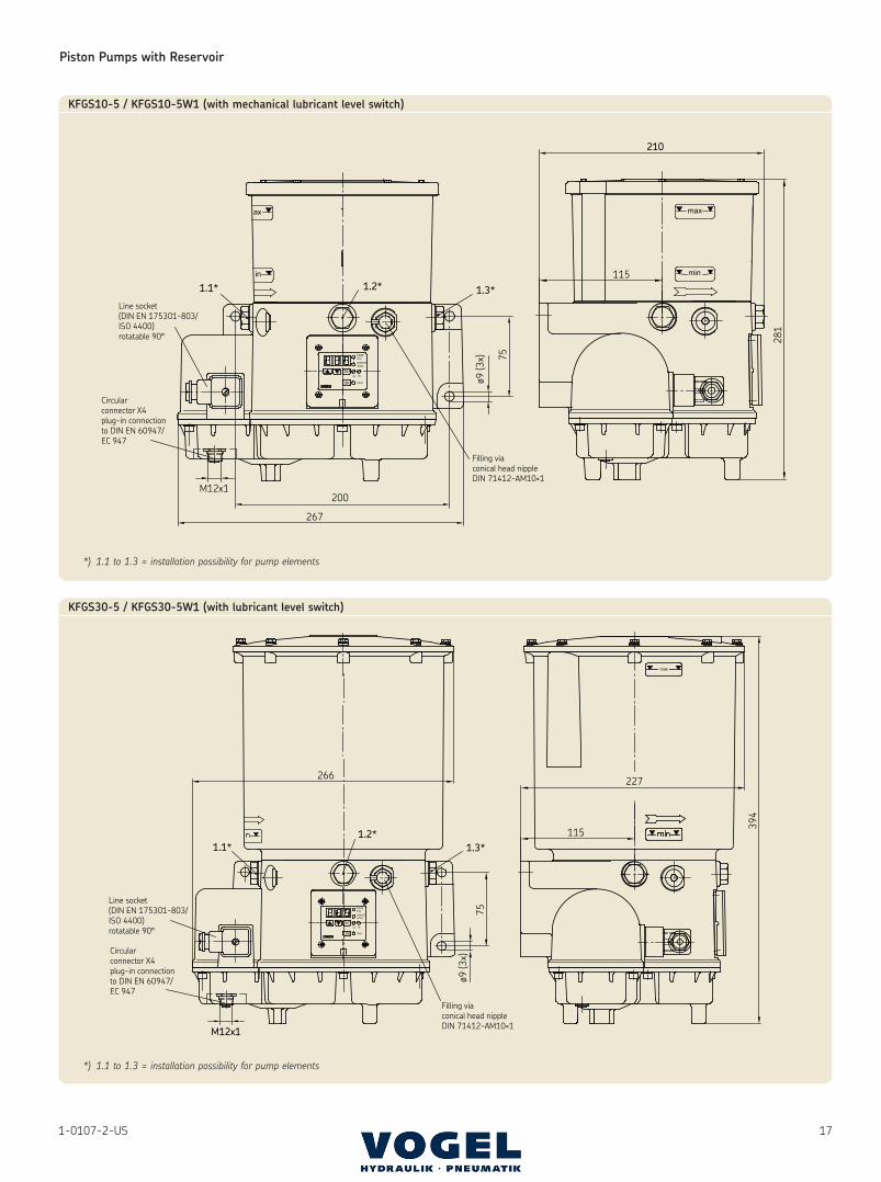
171-0107-2-US
200
267
M12x175
ø9 (3
x)
115
210
1.1* 1.3*1.2*
Filling viaconical head nippleDIN 71412-AM10×1
Line socket(DIN EN 175301-803/ISO 4400)rotatable 90°
Circularconnector X4plug-in connectionto DIN EN 60947/EC 947
281
KFGS10-5 / KFGS10-5W1 (with mechanical lubricant level switch)
*) 1.1 to 1.3 = installation possibility for pump elements
227
115
394
266
75
ø9 (3
x)
M12x1
1.1*1.2*
1.3*
Filling viaconical head nippleDIN 71412-AM10×1
Line socket(DIN EN 175301-803/ISO 4400)rotatable 90°
Circularconnector X4plug-in connectionto DIN EN 60947/EC 947
KFGS30-5 / KFGS30-5W1 (with lubricant level switch)
*) 1.1 to 1.3 = installation possibility for pump elements
This brochure was presented by:
Order No. 1-0107-2-USSubject to change without notice! (09/2008)
The contents of this publication are the copyright of the publisher and may not be reproduced (even extracts) unless permission is granted. Every care has been taken to ensure the accuracy of the information contained in this publication but no liability can be accepted for any loss or damage whether direct, indirect or consequential arising out of use of the information con-tained herein.
All products from VOGEL may be used only for their intended purpose. If operating instructions are supplied together with the products, the provi sions and information therein of specific relevance to the equipment must be observed as well.
In particular, we call your attention to the fact that hazardous materials of any kind, especially the materials classified as hazardous by EC Directive 67/548/EEC, Article 2, Par. 2, may only be filled into VOGEL centralized lubricatio n systems and components and delivered and/or distributed with the same after consultation with and written approval from VOGEL.
All products manufactured by VOGEL are not approved for use in conjunction with gases, liquefied gases, pressurized gases in solution and fluids with a vapor pressure exceeding normal atmospheric pressure (1013 mbars) by more than 0.5 bar at their maximum permissible temperature.
Competence center for industrial applications
Willy Vogel Aktiengesellschaft
SKF Lubrication Solutions
Motzener Strasse 35/37 · 12277 Berlin · Germany
PF 970444 · 12704 Berlin · Germany
Tel. +49 (0)30 72002-0 · Fax +49 (0)30 72002-111
[email protected] · www.vogelag.com
© SKF Group 2008® SKF and VOGEL are registered trademarks of the SKF Group.
Leaflet information1-0107-1-US Progressive feeders1-0107-4-US Grease pump units (Type PF, PFP, PFH)1-4002-1-US Motor drive pump unit GSJBDSK2-008-00-US Grease-lubricating pump FFDSK2-005-00-US Grease-lubricating pump FB1-0107-5-US Piston pumps (Type PPU, PHU)1-0107-6-US Accessories for progressive systems