piston engines: fuel
TRANSCRIPT

Piston Engine Propulsion
Fuel

The complete fuel system of an aircraft can be divided into two principle sections:
• the aircraft section and
• the engine section.
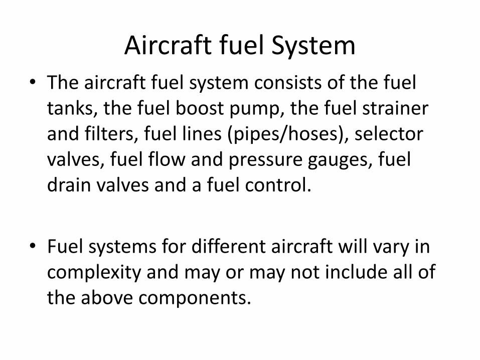
Aircraft fuel System• The aircraft fuel system consists of the fuel
tanks, the fuel boost pump, the fuel strainer and filters, fuel lines (pipes/hoses), selector valves, fuel flow and pressure gauges, fuel drain valves and a fuel control.
• Fuel systems for different aircraft will vary in complexity and may or may not include all of the above components.

Engine Section
• The engine fuel system where the fuel is delivered to the engine driven pump and includes all of the fuel controlling units fitted to the engine itself

Carburettors
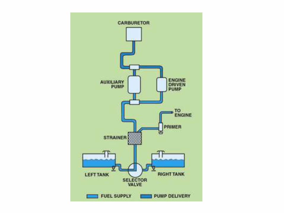
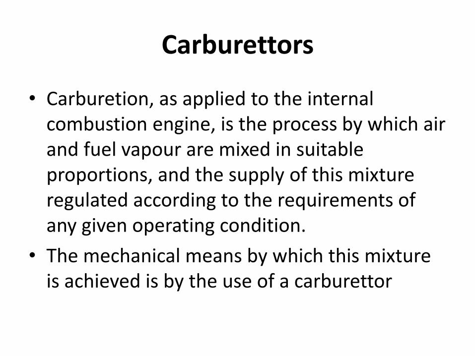
• Carburetion, as applied to the internal combustion engine, is the process by which air and fuel vapour are mixed in suitable proportions, and the supply of this mixture regulated according to the requirements of any given operating condition.
• The mechanical means by which this mixture is achieved is by the use of a carburettor

• The purpose of a carburettor is to supply a well atomized and correctly proportioned mixture of fuel and air to the engine, and to provide a method of limiting the power output by limiting the flow of the mixture.
• Liquid fuels will not burn unless they are mixed with air, or more precisely, with oxygen.
• For the mixture to burn efficiently in an engine cylinder the fuel/air ratio must be kept within a certain range.

• The basic principle of operation is that during the induction stroke of a cylinder the pressure reduces in the inlet manifold and thereby causes the air to flow though the choke tube from the carburettor air inlet.
• Projecting into the choke tube is a fuel nozzle from which petrol is sprayed into the air as droplets of various sizes.


• All carburettors depend on the differential pressure created at the venturi throat to measure the amount of air delivered to an engine and meter the proper amount of fuel.
• When air flows though a venturi, the speed of the air flowing through the venturi throat increases. At the same time, the pressure and temperature of the air in the venturi throat decreases.


Tank
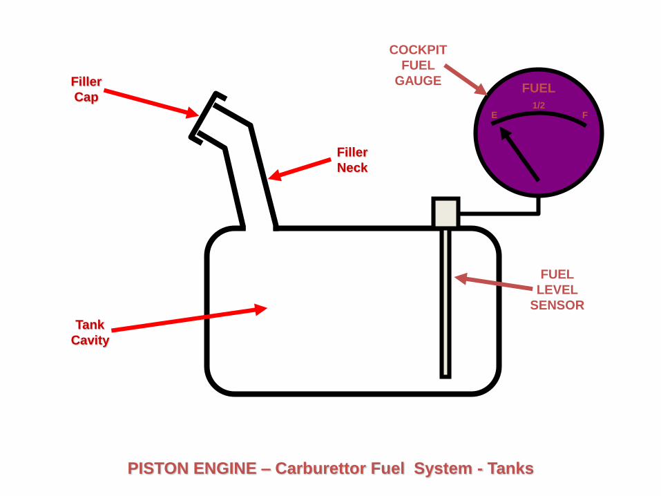
PISTON ENGINE – Carburettor Fuel System
ExhaustInlet
Tank
Cavity
Filler
Cap
Filler
Neck
E F1/2
FUEL
FUEL
LEVEL
SENSOR
COCKPIT
FUEL
GAUGE
PISTON ENGINE – Carburettor Fuel System - Tanks

PISTON ENGINE – Carburettor Fuel System - Tanks
E F1/2
FUEL
E F1/2
FUEL
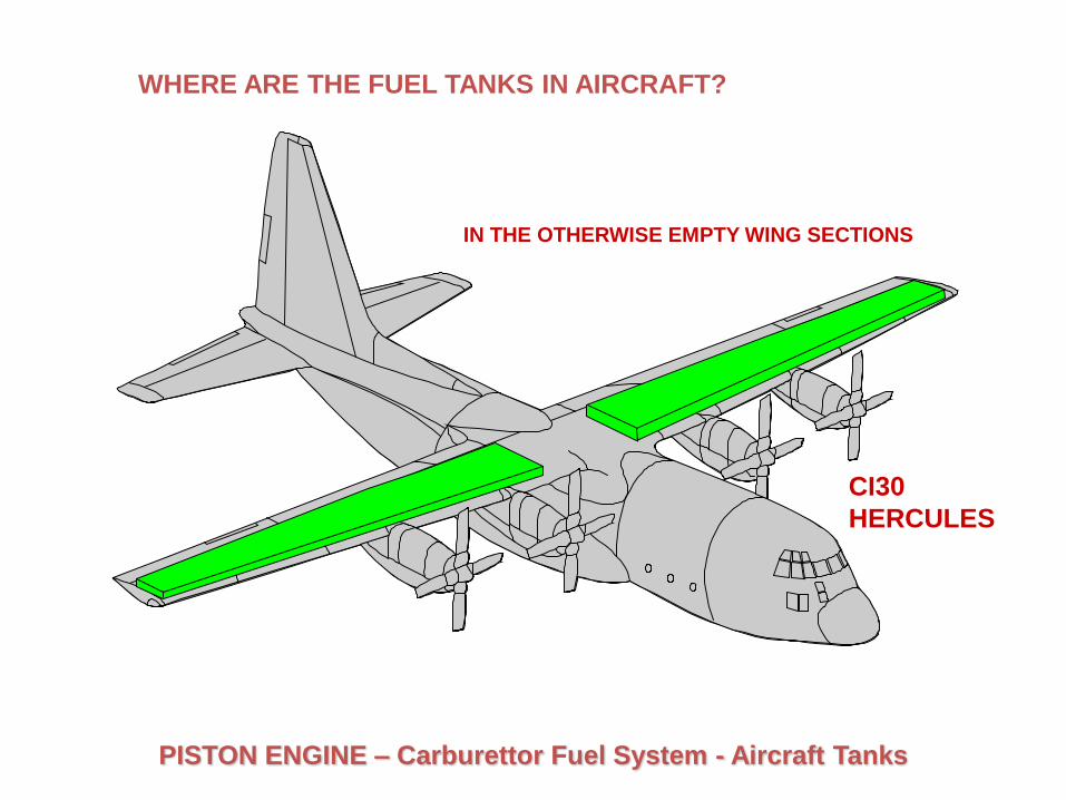
WHERE ARE THE FUEL TANKS IN AIRCRAFT?
IN THE OTHERWISE EMPTY WING SECTIONS
CI30
HERCULES
PISTON ENGINE – Carburettor Fuel System - Aircraft Tanks

Tank
PISTON ENGINE – Carburettor Fuel System
Cockpit
Gauge
Pump
ExhaustInlet

Air
Filter
Tank
PISTON ENGINE – Carburettor Fuel System
Cockpit
Gauge
Pump
Carburettor
ExhaustInlet

Air and
DirtClean
Air
Filter element – corrugated breathable paper
Dirt trapped
by
Filter element
Basic Air Filter OperationPISTON ENGINE – Air Filter

Air
Filter
Tank
PISTON ENGINE – Carburettor Fuel System
Cockpit
Gauge
Pump
Carburettor
ExhaustInlet

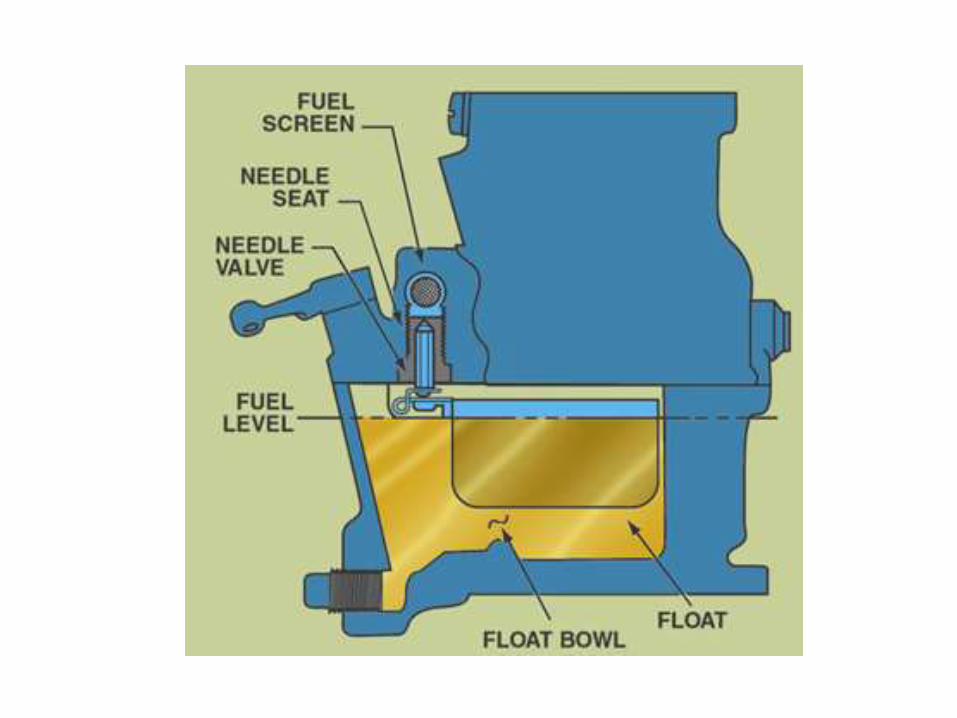
• The carburettor has to control the flow to the engine.
• This is done by the float chamber

Float type carburettor
• This carburettor uses a float to regulate the amount of fuel that enters a carburettor.
• The amount of fuel allowed to flow into a float chamber is controlled by a float operated needle valve installed in the fuel inlet.

SIMPLIFIED PISTON ENGINE FUEL SYSTEM
FLOAT CHAMBER
NEEDLE VALVE AIR VENTVENTURI
FUEL
FEED
FUEL
NOZZLE
SIMPLIFIED PISTON ENGINE FUEL SYSTEM
FLOAT
FUEL
LEVEL
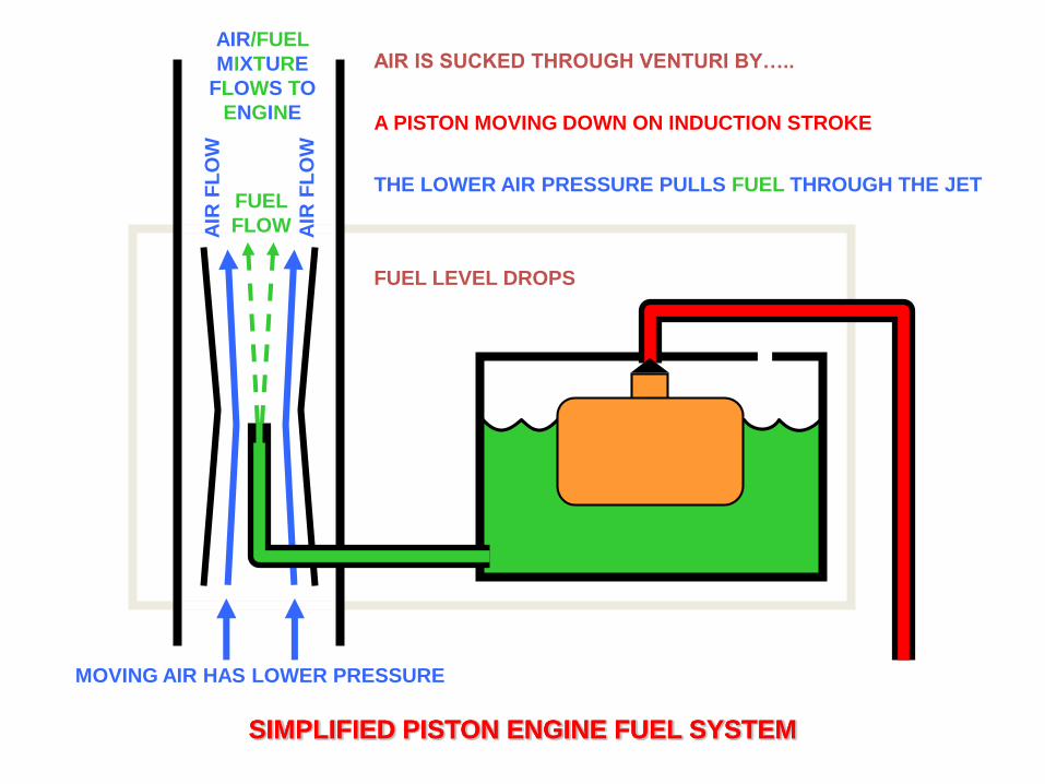
AIR IS SUCKED THROUGH VENTURI BY…..
A PISTON MOVING DOWN ON INDUCTION STROKE
SIMPLIFIED PISTON ENGINE FUEL SYSTEMSIMPLIFIED PISTON ENGINE FUEL SYSTEMSIMPLIFIED PISTON ENGINE FUEL SYSTEM
MOVING AIR HAS LOWER PRESSURE
FUEL
FLOWAIR
FL
OW
AIR
FL
OW
THE LOWER AIR PRESSURE PULLS FUEL THROUGH THE JET
AIR/FUEL
MIXTURE
FLOWS TO
ENGINE
FUEL LEVEL DROPS
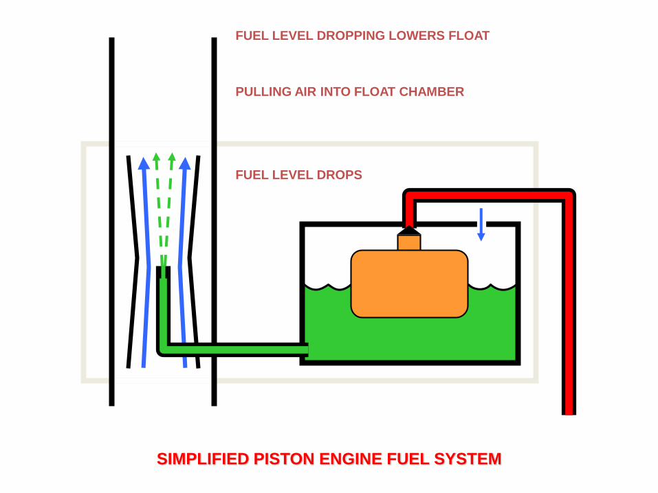
PULLING AIR INTO FLOAT CHAMBER
SIMPLIFIED PISTON ENGINE FUEL SYSTEM
FUEL LEVEL DROPS
FUEL LEVEL DROPPING LOWERS FLOAT
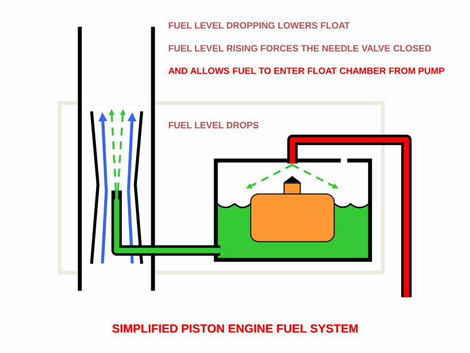
AND ALLOWS FUEL TO ENTER FLOAT CHAMBER FROM PUMP
SIMPLIFIED PISTON ENGINE FUEL SYSTEM
FUEL LEVEL DROPS
FUEL LEVEL RISING FORCES THE NEEDLE VALVE CLOSED
FUEL LEVEL DROPPING LOWERS FLOAT

SIMPLIFIED PISTON ENGINE FUEL SYSTEM
FUEL IS PULLED OUT OF THE FLOAT CHAMBER
ONLY WHEN ONE OF THE PISTONS IS ON THE INDUCTION STROKE
FUEL LEVEL RISING FORCES THE NEEDLE VALVE CLOSED

• To provide for proper engine operation under various engine loads, speeds, and air densities, most carburettors include at least the following systems.
• Main Metering
• Idling
• Mixture Control
• Accelerating
• Power Enrichment or Economizer

Main Metering System
• The purpose of the main metering system is to supply the correct amount of fuel to the engine at all speeds above idle.
• The main metering system is comprised of one or more venturi tubes, a main metering jet and discharge nozzle, and a throttle valve.

• Fuel metering begins with the venturi. As air flows through the venturi, its pressure decreases.
• It is this drop in pressure that the metering system relies on to meter the appropriate amount of fuel.
• In some carburettors, a single venturi is unable to create the pressure drop necessary to meter fuel. In this case, a second boost venturi is installed inside the primary venturi.
• The discharge nozzle delivers fuel to the intake air and in installed between the float chamber and the venturi.
• When an engine is at rest, the fuel level in the discharge nozzle matches that in the float chamber. In most cases, the float maintains a fuel level just below the opening in the discharge nozzle.
• This distance is referred to as the fuel metering head. The purpose of the fuel metering head is to prevent fuel leaking out of the discharge nozzle when the engine is shut down.
• To control the volume of air that passes through a venturi, all carburettors are equipped with a throttle valve.
• The throttle valve consists of a flat, circular piece of metal that is always installed between the venturi and the engine.
• When the throttle valve is positioned parallel with the airflow, the maximum volume of air and fuel enter the engine and the engine develops its maximum power.
• The only thing that limits the volume of air entering the engine is the venturi.
• However, as the throttle valve is moved so that it is perpendicular to the airflow, less air is admitted into the engine and engine power output decreases.


SIMPLIFIED PISTON ENGINE FUEL SYSTEM
LINK TO
THROTTLE
LEVER/PEDAL
THROTTLE
VALVE
VALVE
SPINDLE
VALVE
DISC

SIMPLIFIED PISTON ENGINE FUEL SYSTEM
THROTTLE VALVE
THIS WOULD BE A HIGH THROTTLE SETTING OR ‘FULL –POWER’
OPEN THROTTLE ALLOWS VENTURI TO WORK AT MAXIMUM EFFICIENCY
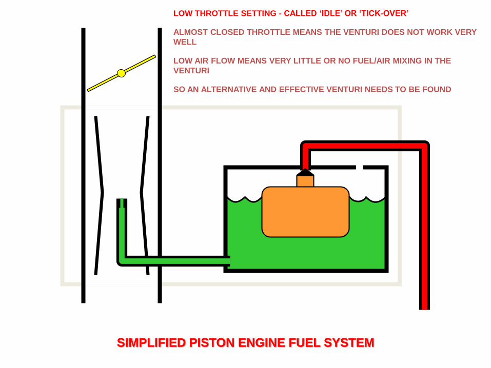
LOW THROTTLE SETTING - CALLED ‘IDLE’ OR ‘TICK-OVER’
ALMOST CLOSED THROTTLE MEANS THE VENTURI DOES NOT WORK VERY
WELL
LOW AIR FLOW MEANS VERY LITTLE OR NO FUEL/AIR MIXING IN THE
VENTURI
SO AN ALTERNATIVE AND EFFECTIVE VENTURI NEEDS TO BE FOUND
SIMPLIFIED PISTON ENGINE FUEL SYSTEMSIMPLIFIED PISTON ENGINE FUEL SYSTEM

T CONTROLS FUEL FLOW
SIMPLIFIED PISTON ENGINE FUEL SYSTEMSIMPLIFIED PISTON ENGINE FUEL SYSTEM
LOW THROTTLE SETTING - CALLED ‘IDLE’ OR ‘TICK-OVER’
EDGE GAPS BECOME THE VENTURI FOR THE LOW AIR FLOW
AT IDLE - SLOW RUNNING JET
• The mixing of air and fuel needs too be done is an efficient way.
• This is done by fitting a diffuser tube.
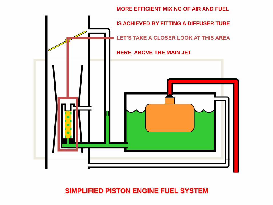
MORE EFFICIENT MIXING OF AIR AND FUEL
IS ACHIEVED BY FITTING A DIFFUSER TUBE
SIMPLIFIED PISTON ENGINE FUEL SYSTEM
HERE, ABOVE THE MAIN JET
LET’S TAKE A CLOSER LOOK AT THIS AREA
IDLE SETTING FUEL
SUPPLIED VIA IDLE JET
OPEN THROTTLE
IDLE JET STOPS WORKING
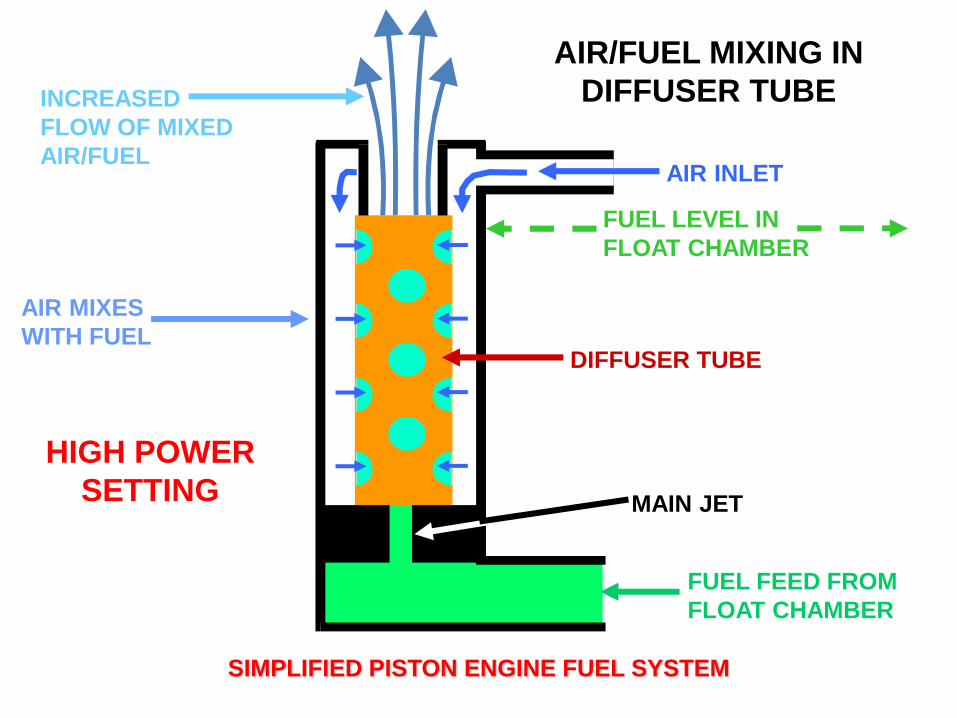
CRUISE SETTINGHIGH POWER
SETTING
AIR INLET
DIFFUSER TUBE
INCREASED
FLOW OF MIXED
AIR/FUEL
FUEL FEED FROM
FLOAT CHAMBER
MAIN JET
AIR MIXES
WITH FUEL
AIR/FUEL MIXING IN
DIFFUSER TUBE
FUEL LEVEL IN
FLOAT CHAMBER
SIMPLIFIED PISTON ENGINE FUEL SYSTEM
SIMPLIFIED PISTON ENGINE FUEL SYSTEMSIMPLIFIED PISTON ENGINE FUEL SYSTEMSIMPLIFIED PISTON ENGINE FUEL SYSTEM
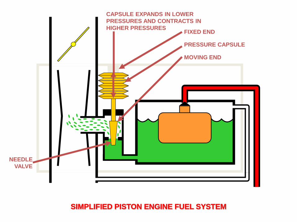
FIXED END
MOVING END
NEEDLE
VALVE
CAPSULE EXPANDS IN LOWER
PRESSURES AND CONTRACTS IN
HIGHER PRESSURES
PRESSURE CAPSULE

SIMPLIFIED PISTON ENGINE FUEL SYSTEMSIMPLIFIED PISTON ENGINE FUEL SYSTEMSIMPLIFIED PISTON ENGINE FUEL SYSTEM
AT LOW ALTITUDE – HIGHER ATMOSPHERIC PRESSURE
CAPSULE CONTRACTED
HIGH FUEL FLOW
AT HIGH ALTITUDE – LOWER ATMOSPHERIC PRESSURE
CAPSULE EXPANDS

SIMPLIFIED PISTON ENGINE FUEL SYSTEMSIMPLIFIED PISTON ENGINE FUEL SYSTEMSIMPLIFIED PISTON ENGINE FUEL SYSTEM
AT HIGH ALTITUDE – LOWER ATMOSPHERIC PRESSURE
CAPSULE EXPANDS
CLOSING FUEL ORIFICEE AND REDUCING FUEL FLOW

BatteryFuel Tank
Pump
Warm Up
Regulator
Fuel
Accumulator
Ignition
Switch
Filter
Primary
Pressure
Valve
Air Sensor
Plate
Mixture Control
Unit (Fuel
Distributor Valve)
Auxiliary Air
Device
Cold Start
ValveIdle Speed
Adjuster
Fuel
Injector
Throttle
Valve
Engine Temp
Sensor
Safety
Relay
Air
Inlet
High Pressure Fuel
Low Pressure Fuel
Supply Pressure Fuel
Servo Pressure Fuel
Electrical Signal
Legend
PISTON ENGINE – Hydro-Mechanical Fuel Injection System
(from Air
Filter)

Air Filter
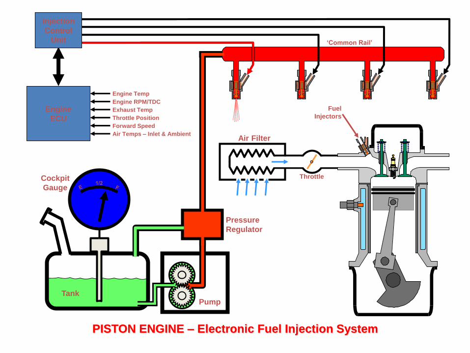
PISTON ENGINE – Electronic Fuel Injection System
Engine
ECU
TankPump
Cockpit
Gauge
Pressure
Regulator
Injection
Control
Unit
Engine Temp
Engine RPM/TDC
Exhaust Temp
Throttle Position
Forward Speed
Air Temps – Inlet & Ambient
Fuel
Injectors
‘Common Rail’
Throttle
• An automatic mixture control is required to totake into account that at higher altitude there is less air, so therefore less fuel is required.
• This change in fuel flow is controlled by a device that can sense the change in air pressure.
• It is called a pressure bellows or pressure capsule.

BatteryFuel Tank
Pump
Warm Up
Regulator
Fuel
Accumulator
Ignition
Switch
Filter
Primary
Pressure
Valve
Air Sensor
Plate
Mixture Control
Unit (Fuel
Distributor Valve)
Auxiliary Air
Device
Cold Start
ValveIdle Speed
Adjuster
Fuel
Injector
Throttle
Valve
Engine Temp
Sensor
Safety
Relay
Air
Inlet
High Pressure Fuel
Low Pressure Fuel
Supply Pressure Fuel
Servo Pressure Fuel
Electrical Signal
Legend
PISTON ENGINE – Hydro-Mechanical Fuel Injection System
(from Air
Filter)
Air Filter
PISTON ENGINE – Electronic Fuel Injection System
Engine
ECU
TankPump
Cockpit
Gauge
Pressure
Regulator
Injection
Control
Unit
Engine Temp
Engine RPM/TDC
Exhaust Temp
Throttle Position
Forward Speed
Air Temps – Inlet & Ambient
Fuel
Injectors
‘Common Rail’
Throttle