existing state of art of free-piston engines · existing state of art of free-piston engines ......
TRANSCRIPT

1204
Agronomy Research 15(S1), 1204–1222, 2017
Existing state of art of free-piston engines
V. Raide,* R. Ilves, A. Küüt, K. Küüt and J. Olt
Institute of Technology, Department of Agricultural and Production Engineering,
Estonian University of Life Sciences, Fr.R. Kreutzwaldi 56, EE51014 Tartu, Estonia *Correspondence: [email protected]
Abstract. Free-piston engines (FPE), as power generators for electricity and hydropower
solutions, have come under intensive research and development during the last decade. The rapid
development of information technology provides an opportunity to return to FPE technology
development due to better levels of control and management in terms of the engine’s work. What
is more, changed environmental requirements are imposing stricter conditions upon the
development of internal combustion engines. More effective solutions which ensure lower
exhaust emissions, which are able to consume a variety of conventional and renewable fuels
without any engine modification or rebuild taking place, and which work well with a very wide
variety of ambient temperature conditions. However, commercially available or production-ready
compact and stable free-piston engine solution are still absent. The objectives of this article are
the innovative and novel features of FPE and their influence on engine operations and power
production. The article maps the FPE technology and conducts a fact analysis. Various technical
solutions, experiments, and mathematical calculations are discussed and are presented critically,
along with potential pros and cons. This paper will epitomise the discussions outlined above with
one possible theoretical technical solution for FPE, this being the electrical power generator.
Key words: internal combustion engine, free-piston linear alternator, engine generator.
INTRODUCTION
The world’s growing electricity deficit forces us to evaluate other options when it
comes to energy resources and technology. Over the next two decades, oil will remain
the world’s main energy source but it will not cover the growing demand for energy.
This perspective compels us to develop combustion technology and to find energy
alternatives. Fuel converted to electrical power via ‘engine generators’ (GENSET) is a
relatively quick process. Mobile power generation is under constant development (Lund,
2008) and solutions are sought in many sectors. The US Land Forces stated that, in 2020,
new technology will produce 75% of operation electricity (Defence Update, 2003), and
the EU will replace conventional fuels with 20% renewable energy. These objectives
determine the development directions in all energy areas including the automotive
industry.
Environmentally-friendly combustion technology will be progressively introduced
and engine production will evolve in the direction of hybrid engines. In terms of the
automobile industry, significant technological developments focus primarily on electric
and hybrid cars which have the potential to consume less energy and reduce emissions.
Developments influence and determine mobile electricity production with renewable

1205
fuels as being key to progress. One internal combustion engine research area is the free-
piston engine (FPE), which was abandoned in the middle of the previous century but
which is currently making something of a comeback in terms of low levels of power
production. The return of FPE technology is significantly influenced by IT developments
which provide faster processors and more sensitive sensors to control the way engines
work. Technology compactness and improved capacity parameters make FPE an
attractive and promising technology. More deeply FPE-related concepts are being
studied by Achten and Aichlamyr (Achten, 1994; Aichlmayr, 2002) but technology has
evolved and improved in the meantime.
In this article, FPE studies are provided with an overview and are cited in
association with the developments of the previous decade. Chapters are divided based
upon problems and in highlighting the pros and cons of the technology. According to the
analysis which has been carried out, (1) FPE concepts are mapped out and the list of
usable technology developments is improved by the addition of the latest inventions
(Table 1); (2) the engine mechanics are debated in connection with simulations and
engine control; (3) the principles behind starting-up an engine are critically reviewed,
along with the provision of technical examples; and (4) focuses on engine combustion
stability and starting an analysis which was carried out in particularly changing load
conditions. Finally, an overview is presented and discussed along with the provision of
an FPE solution for the mobile GENSET.
ENGINE CONCEPTS
The FPE can be divided into three groups by its actions and extractions (Mikalsen
& Roskilly, 2007), and by more complex configurations using three cylinders and four
pistons (Hung et al., 2015). The configurations mentioned use piston motion in order to
achieve any useful work. For example, the technology implements and supercharges
power turbine rotational movement. The single piston FPE consists of only a few parts:
(1) the cylinder; (2) the load device; and (3) the rebound device which stores energy for
the next compression. The surplus energy is directed towards hydraulic, pneumatic, or
electrical power production. The dual FPE configuration skips the rebound chamber
since combustion provides compression for the next stroke. This omission increases the
overall power to weight ratio. Dual technology is the area which sees the most research
and development, so a number of patented designs are available. The patents are found
in all three types of hydraulic, pneumatic, and electrical power production. The challenge
in terms of FPE is in achieving control of: (1) the piston motion; (2) the stroke length;
and (3) compression due to sensitivity to load and cycle-to-cycle variations (Aichlmayr,
2002). The most common designs are illustrated and general pros, cons, and loads are
described in Table 1.

1206
Table 1. Common free-piston engine designs
Configuration Representation Pros / Cons/General
description/ Load
a) Single piston and one
cylinder solution (Achten
et al., 2000; Zhang et al.,
2015a; Zhang et al., 2015b
Zhao et al., 2010; Zhao et
al., 2013; Zhao et al., 2014;
Brunner et al., 2005;
Hibi&Ito, 2004; Kock et
al., 2013)
Simple design,
compact, unbalanced,
counterweights may be
needed, allows long
stroke, scavenging or
injection fuelling,
exhaust ports or valves
for the outlet.
b) Single piston rod, two
piston and two cylinder
solution (Mikalsen et al.,
2010; Jia et al., 2014a;
Jia et al., 2015a; Jia et al.,
2015b, Mikalsen &
Roskilly, Part 1, 2010;
Xiao et al., 2010; Tikkanen
et al., 2000; Clark et al.,
1998; Blarigan et al., 1998;
Fredriksson & Denbratt,
2004; Xu & Chang, 2010;
Robinson & Clark, 2016)
Every revolution two
power strokes, better
power output, massive
piston causes
unbalance, long stroke,
challenge to control,
great power output,
loading hydraulic or
electric generator,
scavenging or injection
fuelling, exhaust ports
or valves for outlet.
c) Two opposed piston,
two piston rods and one
cylinder solution
(Wu et al., 2014;
Xu et al., 2011;
Zhou et al., 2005)
Concurrent
combustion, separate
bounce, and load
chambers, challenge to
control, loading
hydraulic or producing
high pressure for the
turbine, scavenging or
injection fuelling,
exhaust ports or valves
for the outlet.
d) Two opposed piston,
two piston rods and one
cylinder with
synchronisation rods
(Achten, 1994;
Hanipah et al.,2015;
Mikalsen & Roskilly,
2007a; Aichlmayr, 2002)
Concurrent combustion,
piston synchronization,
minimal vibration,
separate bounce and
load chambers, loading
hydraulic or producing
high pressure for
turbine, scavenging or
injection fuelling,
exhaust ports or valves
for the outlet.

1207
Table 1 (continued) e) Four piston, opposed –
dual, two piston rods and
three cylinders solution
(Nguyen et al., 2015)
Four pistons, three
combustion chambers,
two separate bounce and
load chambers, loading
hydraulic, injection
fuelling, exhaust ports.
f) Four piston, opposed, two
cylinder solution
(Li et al., 2015; Zhang et
al., 2015)
Four pistons, two
combustion chambers,
concurrent combustion,
compression ignition,
three interconnected
hydraulic chambers,
intake and exhaust
ports.
The FPE is a reciprocating engine, one which is frequently termed a linear piston
engine, in which the steady piston moves and transforms thermal energy into power.
Unlimited piston motion and the variable clearance volume Vc between the ‘top dead
centre’ (TDC) and the ‘bottom dead centre’ (BDC) is missing from the rod and crank
mechanism. The FPE configurations differ but at least have: (1) a combustion chamber;
(2) rebound or bounce-storing energy; (3) load absorbing or consuming energy. Fewer
moving parts decrease friction and increase system efficiency as piston rings, bearings,
bounce, and rebound result in minimal kinematic constraints (Aichlmayr, 2002). The
FPE compression and expansion (power) stroke is similar to the revolution of a two-
stroke engine. The compression stroke starts at BDC, after the charge is sucked in to the
cylinder and it ends when the charge is compressed until the pressures equalise. The
compression stroke uses released rebound storage energy. The compression or spark
initiates combustion in TDC and thermal energy converts into kinetic energy through
rapidly expanding gasses. The expansion lasts until blow-down is achieved, in BDC,
since the exhaust port or valve opens and releases exhaust gasses. The inlet port or valve
opens and scavenges (compresses) a charge into the cylinder and then the cycle repeats.
The FPE designs may vary but operational principles are the same (Mikalsen & Roskilly,
2007a).
The FPE is exploited by electric generators, and by hydraulic and pneumatic systems. In
hydraulic systems, pressures are achieved via a small piston mass and the efficiency rate
is relatively high. The hydraulic control system keeps the discharge pressure constant.
Linear electric generators are compact power packs due to the use of ferromagnetic
materials or permanent magnets in pistons mechanisms. In linear electric generators, the
oscillation frequency is set in accordance with the load. The FPE advantages and
challenges are as follows:
The FPE advantages:
· A structurally simple machine;
· A variable compression ratio during operation;
· Variable compression allows high compression ratios;

1208
· Allows for multi-fuel operation;
· Each stroke generates power;
· Piston movement is not limited by crankshaft radius;
· The missing crankshaft reduces the geometry significantly;
· A significant kW to kg ratio;
· Allows a long piston stroke to be implemented;
· Small frictional losses;
· Good volumetric efficiency;
· Lower temperature release due to a rapid burning process;
· Lower fuel consumption due to lower frictional losses;
· Reduced emissions;
· Able to work in very low temperature conditions;
· Low vibrations due to the crankshaft being absent.
Challenges to overcome are these:
· The starting process;
· Piston movement control;
· Variable piston stroke which leads to poor volumetric efficiency;
· Precise load control;
· An accurate fuel mixture;
In conclusion, normally the crankshaft controls and stores energy for the next
stroke. The FPE employs a two-stroke principle as it needs a power stroke in every cycle.
The one-piston FPE reciprocates in terms of combustion and for the necessary rebound
force in balance with the controlled load. The proper combustion characteristics ensure
that the engine works as expected and the residue is diverted for power production. The
FPE needs enough computing power, accurate algorithms, quick reaction sensors, and
powerful enforcement mechanisms to control the piston, scavenging, ignition, and
exhaust release. Otherwise, the engine management process fails.
ENGINE MECHANICS
The FPE is missing a crankshaft, and instead the load force is directly coupled to
the piston. The calculations and simulations based on the balance of piston motion on
the engine power mode. The compression ratio rc (rc = total cylinder volume Vt / cylinder
clearance volume Vc) and cylinder volume V (m3) calculates in a similar way to
calculations for crankshaft engines, but volume V at any crank angle j (degrees) is
problematic. The piston location calculations for crankshaft engines are take into account
the connecting rod length l (cm), crank radius α (cm), and time- change rate dependent
on crank angle j. In terms of FPE, piston motion is derived from free-body motion and,
therefore, excludes crankshaft radius and piston friction by side forces. The main piston
motion characteristics in the FPE are shown in Fig. 1 (Aichlmayr, 2002; Mikalsen &
Roskilly, 2007a).
1209
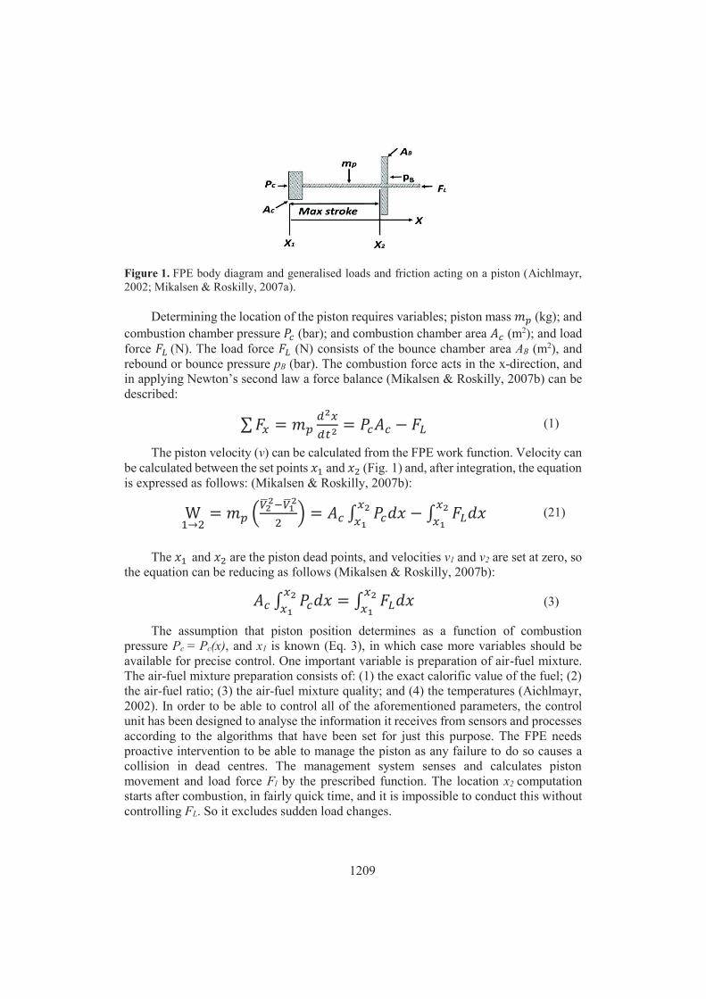
Figure 1. FPE body diagram and generalised loads and friction acting on a piston (Aichlmayr,
2002; Mikalsen & Roskilly, 2007a).
Determining the location of the piston requires variables; piston mass (kg); and
combustion chamber pressure (bar); and combustion chamber area (m2); and load
force (N). The load force (N) consists of the bounce chamber area AB (m2), and
rebound or bounce pressure pB (bar). The combustion force acts in the x-direction, and
in applying Newton’s second law a force balance (Mikalsen & Roskilly, 2007b) can be
described:
(1)
The piston velocity (v) can be calculated from the FPE work function. Velocity can
be calculated between the set points and (Fig. 1) and, after integration, the equation
is expressed as follows: (Mikalsen & Roskilly, 2007b):
(21)
The and are the piston dead points, and velocities v1 and v2 are set at zero, so
the equation can be reducing as follows (Mikalsen & Roskilly, 2007b):
(3)
The assumption that piston position determines as a function of combustion
pressure Pc = Pc(x), and x1 is known (Eq. 3), in which case more variables should be
available for precise control. One important variable is preparation of air-fuel mixture.
The air-fuel mixture preparation consists of: (1) the exact calorific value of the fuel; (2)
the air-fuel ratio; (3) the air-fuel mixture quality; and (4) the temperatures (Aichlmayr,
2002). In order to be able to control all of the aforementioned parameters, the control
unit has been designed to analyse the information it receives from sensors and processes
according to the algorithms that have been set for just this purpose. The FPE needs
proactive intervention to be able to manage the piston as any failure to do so causes a
collision in dead centres. The management system senses and calculates piston
movement and load force Fl by the prescribed function. The location x2 computation
starts after combustion, in fairly quick time, and it is impossible to conduct this without
controlling FL. So it excludes sudden load changes.
1210
ENGINE START UP PRINCIPLES
The absence of a flywheel concludes any remaining problems which need to be
overcome. The FPE piston’s missing connection with any mechanical parts directly
influences the start-up process. The start-up problems occurred regardless of
configuration, and researchers report that the start for a dual-piston engine is the real
problem (Noren & Erwin, 1958; Aichlmayr, 2002; Nemecek & Vysoky, 2006; Mikalsen
& Roskilly, 2007a; Zulkifli et al., 2008; Xu & Chang, 2010). The FPE must start the
combustion on the first stroke (Braun & Schweitzer, 1973) and the start-up requires
additional technical equipment. The cylinder is fuelled, the piston is positioned on the
maximum value, and required pulse energy is released (Farmer, 1947; Noren & Erwin,
1958; Aichlmayr, 2002). The FPE is started with a spring or a hydraulic system that can
generate the piston movements in the cylinder (bounce or rebound), (Farmer, 1947;
Aichlmayr, 2002), with this being the most widely-used practical method (London &
Oppenheim, 1952).
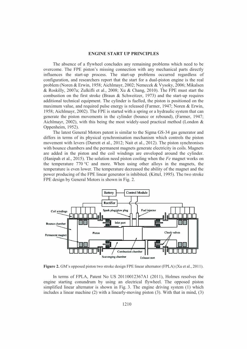
The latest General Motors patent is similar to the Sigma GS-34 gas generator and
differs in terms of its physical synchronisation mechanism which controls the piston
movement with levers (Durrett et al., 2012; Nait et al., 2012). The piston synchronises
with bounce chambers and the permanent magnets generate electricity in coils. Magnets
are added in the piston and the coil windings are enveloped around the cylinder.
(Hanipah et al., 2015). The solution need piston cooling when the Fe magnet works on
the temperature 770 °C and more. When using other alloys in the magnets, the
temperature is even lower. The temperature decreased the ability of the magnet and the
power producing of the FPE linear generator is inhibited. (Kittel, 1995). The two stroke
FPE design by General Motors is shown in Fig. 2.
Figure 2. GM’s opposed piston two stroke design FPE linear alternator (FPLA) (Xu et al., 2011).
In terms of FPLA, Patent No US 20110012367A1 (2011), Holmes resolves the
engine starting conundrum by using an electrical flywheel. The opposed piston
simplified linear alternator is shown in Fig. 3. The engine driving system (1) which
includes a linear machine (2) with a linearly-moving piston (3). With that in mind, (3)

1211
moves along a path between the first end (4) with a first combustion chamber (5) which
has a first fuel source and spark plug (6), and a second end (7) with a second combustion
chamber (8) with a second fuel source and spark plug (9). A first coil (10) has windings
around the path of the linearly-moving piston. It can be seen that (3) is positioned
towards the first end (4). Similarly, a second coil (11) is also wound around the path and
is positioned towards the second end (7) (12). Other items are a third coil (13) rotary
machine, (14) fourth coil, (15) transmission, (16) variable speed motor, (17) rotor, (15)
transmission of speed. The FPLA connects electrically via two sets of coils to a rotary
machine (middle) and a battery source via a converter. In addition, a variable-speed
motor connects mechanically via a gear box to the rotary machine as well as being
electrically connected to the whole system via two sets of coils. This FPLA uses stored
energy from batteries to create a starting electrical current in the first and second coils.
The starting magnetic field moves the piston and creates the magnetic field in the
cylinder coils. The converter starts the engine and converts electricity. The external coils
and rotating bodies are kept limited in size and mass. The alternative solution is a
programmable controller which generates the needed current and oscillation directly in
the engine coils (Holmes, 2011).
Figure 3. FPE starting system principle (Holmes, 2011).
The turbo charged energy converter, Patent No EP 1540155B1 (Max et al., 2005),
is shown in Fig. 4. The energy converter system (1) consist of, comprising piston
(2 & 3), combustion chamber (4 & 5), inlet (6 & 7), and outlet (8 & 9) manifold, inlet
and outlet valves (10, 11, 12, & 13). One inlet and one outlet valve are controllable
separately by control unit in order to regulate the beginning of suction and compression
stroke. When piston starts moving, the magnets in the generator affect
electromagnetically the coil windings. Differences compare to solution in Fig. 2 is, that
magnets are added in to the piston rod. This solution is less sensitive to temperatures but
load of generator has impact for piston velocity.

1212
Figure 4. FPE linear alternator (Max et al., 2005).
The batteries operate the linear alternator as a linear motor. The piston is oscillated
in the cylinder, building to a higher compression each cycle until sufficient compression
is developed for auto-ignition. The fuel which is introduced into the engine ensures self-
powered operation. A cold starting process is a special case since a considerable amount
of compression is required to achieve the automatic ignition temperature (Max et al.,
2005).
The linear alternator allows the FPE to be started without the need for any
additional systems and this restrains FPE to compact dimensions. An engine which starts
up by means of a battery or supercapacitor is a reasonable prospect when it comes to
smoothing out load peaks which can cause malfunctions in engine operation. Any FPE
starting without external aids ensures system compactness. When using the spring, hydro
or pneumatic systems as engine starters, additional developments in FPE construction
are necessary. What’s more, when using pneumatic pumps or electrical engines as FPE
starters, the mass of the FPE increases. This is problematic in terms of the transportation
of FPE.
ENGINE START-UP COMBUSTION STABILITY
The opposed piston FPE generator (FPEG) consists of mechanical resonance
starting (Atkinson et al., 1999; Li et al., 2008; Jia et al., 2014a; Jia et al., 2015b). The
spring theoretical model was researched and the start-up experiment was conducted on
a prototype engine. They investigated engine control, input parameters and misfire
reasons. The FPEG (a) simplified scheme and (b) prototype is shown in Fig. 5. The
stoichiometric mixture takes place in the intake manifold. The ignition system consists
of a 2V battery, ignition coil, and spark plug, which is activated automatically after the
required compression has been achieved. The generator motors the start-up process and
switches the generator mode after the starting-up process has been completed. The
magnets are placed in the centre of the piston and the stator coil is connected to an
electrical load absorber. All three starting phases: 1) starting; 2) the electrical motor

1213
phase; and 3) the generator switch phase is to be coupled up to a proper control system
in order to ensure transition and stable running. All of the processes are measured by
system sensors and data is sent to electrical controllers: 1) starting; 2) ignition;
3) electrics; and 4) the external load control system (Jia et al., 2015b).
Figure 5. FPE generator simplified design (a) (Jia et al., 2014a) and the prototype (b) (Jia et al.,
2015b).
Practical tests of FPE starting are carried out. Testing theory based on the factor
that the FPEG is free of side forces, and system friction is low in proportion to electrical
force within the start-up. In the practical tests, the theoretical starting force of FPE was
60N and in this case, it illustrates the crossing of the friction forces. The practical
experimental results are illustrated in Fig. 6. Piston displacement extends step-by-step,
until it reaches to maximum value. Gas pressure in the cylinder and maximum velocity
of the piston increases with each stroke. Suitable compression value in FPE cylinder was
reached in less than a second (Jia et al., 2014). The amplitude of piston movements and
velocity increased in respect to the completion of the stroke time (Fig. 6). Fig. 6 shows
that, in addition to friction, air leakage, heat transfer, and vibration all exist as additional
drains on energy production. Piston movement amplitude, maximum piston velocity, and
cylinder pressure peak which increases gradually by resonance and also increases rapidly
(at 0.8 fractions of a second) all serve to achieve the target for ignition. Later research
will need to focus on new targets, these being achieving the compression ratio (8:1) and
the cylinder pressure (10 bar). The crossing of the friction forces, the static friction force
(60N), was set as a maximum theoretical force. In practical experiments it emerged that
it was twice as much as 60N. In FPE tests, forces were applied which were between 80N
to 125N at a 15N interval. At 80N (8.5Hz~510 cycle per min), the maximum cylinder
pressure of 5 bar after four cycles was achieved and remained at the same level.
1214
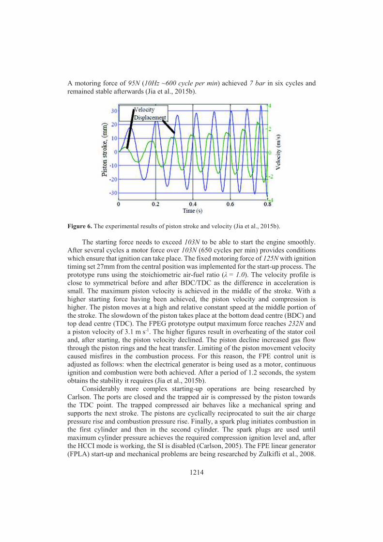
A motoring force of 95N (10Hz ~600 cycle per min) achieved 7 bar in six cycles and
remained stable afterwards (Jia et al., 2015b).
Figure 6. The experimental results of piston stroke and velocity (Jia et al., 2015b).
The starting force needs to exceed 103N to be able to start the engine smoothly.
After several cycles a motor force over 103N (650 cycles per min) provides conditions
which ensure that ignition can take place. The fixed motoring force of 125N with ignition
timing set 27mm from the central position was implemented for the start-up process. The
prototype runs using the stoichiometric air-fuel ratio (λ = 1.0). The velocity profile is
close to symmetrical before and after BDC/TDC as the difference in acceleration is
small. The maximum piston velocity is achieved in the middle of the stroke. With a
higher starting force having been achieved, the piston velocity and compression is
higher. The piston moves at a high and relative constant speed at the middle portion of
the stroke. The slowdown of the piston takes place at the bottom dead centre (BDC) and
top dead centre (TDC). The FPEG prototype output maximum force reaches 232N and
a piston velocity of 3.1 m s-1. The higher figures result in overheating of the stator coil
and, after starting, the piston velocity declined. The piston decline increased gas flow
through the piston rings and the heat transfer. Limiting of the piston movement velocity
caused misfires in the combustion process. For this reason, the FPE control unit is
adjusted as follows: when the electrical generator is being used as a motor, continuous
ignition and combustion were both achieved. After a period of 1.2 seconds, the system
obtains the stability it requires (Jia et al., 2015b).
Considerably more complex starting-up operations are being researched by
Carlson. The ports are closed and the trapped air is compressed by the piston towards
the TDC point. The trapped compressed air behaves like a mechanical spring and
supports the next stroke. The pistons are cyclically reciprocated to suit the air charge
pressure rise and combustion pressure rise. Finally, a spark plug initiates combustion in
the first cylinder and then in the second cylinder. The spark plugs are used until
maximum cylinder pressure achieves the required compression ignition level and, after
the HCCI mode is working, the SI is disabled (Carlson, 2005). The FPE linear generator
(FPLA) start-up and mechanical problems are being researched by Zulkifli et al., 2008.

1215
The spark ignited dual FPE uses a brushless linear motor to produce the required start-
up force. The research focuses on the FPLA mechanical model and provides simulations
for different motoring force values. The start-up strategy proposes the presence of air
compression in the engine cylinders prior to combustion (Zulkifli et al., 2008).
The generator coils will be loaded with a fixed DC voltage, and an open-loop,
rectangular commutation of the input current and a high motoring force reciprocates the
translator at small amplitudes until the amplitude and speed of the mechanical resonance
reach the required parameters for combustion (Zulkifli et al., 2008). A starting method
which uses the resonance in a diesel free-piston linear alternator with a commercial
permanent magnet tubes has shown that: (1) the FPLA can be started by using the air-
spring characteristics and with a comparatively small thrust force, but a greater thrust
force will engage the start-up in a few less cranking cycles; (2) the load on the linear
alternator is associated with the cylinder bore measure and the maximum
electromagnetic force is approximately proportional to the bore square measure; (3) with
the same fuel/air equivalence ratio and external load resistance, a longer effective stroke
length helps to increase the compression ratio and also served to indicate the efficiency
of the free-piston engine; (4) with the same fuel/air equivalence ratio and external load
resistance, it can generally be seen that a longer effective stroke length leads to a higher
power output level (Mao et al., 2011). Researches of the diesel FPE start-up and working
parametric analysis (Mikalsen & Roskilly, 2010), and detailed engine control strategies
(Mikalsen & Roskilly, Part 1, 2010; Mikalsen & Roskilly, Part 2, 2010; Mikalsen et al.,
2010) reached on the similar results.
The FPE idea is simple and compact power pack technology, which is easily
maintained due to a few simple engine parts. The engine’s external starting extras
include system ballast, which means that linear or rotational electrical generators
maintain the preliminary measurements and are used for operation of normal engine. The
stable duty-cycle is achieved by controlling the piston stroke and energy storage. After
solving the FPE management process satisfactorily, the unique features of this resource
can be released onto markets so that they can compete with existing crankshaft engine
technology. The scavenging, spark, or compression ignition and exhaust release process
represent a major challenge for all types of FPE. The piston dictates consequent
processes which include compress control. In order to be able to ensure smooth running,
the control systems have to start with the nature of the fuel itself and the fuel preparation
process. When it comes to piston motion calculations using different fuels, the
algorithms can be developed. FPE control requires precise algorithms and optimised
operating software for the ‘virtual crankshaft’. The piston speed is high, and data traffic
needs to be extremely rapid when it comes to sending and receiving sensor information
and executing commands. Control functions can only be carried out by using sensitive
sensors and high speed reaction valves.
OUTLOOK
The FPE frequency depends upon P0 and L loads. Therefore the fuel mixture, the
moving piston (of between 4–15 kg), the ignition position, and the loads need advanced
combustion control strategies in place to be able to properly manage them. FPE load
regulation is one method of controlling the combustion process. Fuel injection and
exhaust manipulation have only a limited level of influence on the engine’s operation

1216
and the methods used for fine tuning. Stroke-to-stroke manipulation is carried out by
reducing the external excitation and increasing the damping coefficient. The method
prevents engine damage and bounce chamber damping. The piston rod stiffness provides
a positive effect on external excitation and ignores the initial state. The pressure peaks
and working cycle variations are controlled by the piston motion estimation and by
accurate injection timing. When using one piston hydraulic FPE, the process of
controlling it is less problematic than when using rigidly connected pistons, because
every revolution consists of two power strokes. The first piston’s compression is the
second piston’s, which means that the system management reaction rates must be higher.
The timing-based injection method reduces pressure variability and means that the
resultant kinetic energy will be used. The aforementioned method has a significant effect
on the reliability and simplicity of engine operations. The method allows the pressure in
the combustion to be controlled, along with the forming of the air-fuel mixture.
Accordingly, the most important controlling principle is the control of the entire fuel
system, starting from fuel chemical kinetics and subsequent gas dynamics.
The varied stroke causes fuel injection timing problems. The problem can be solved
by limiting of the piston stroke interval. The piston oscillation frequency must be
increased step by step, until the piston stroke has reached to the maximum value. The
load control must restrained within tight limits otherwise the piston hits the cylinder head
and the engine stops. The same problem was revealed in the engine starting process,
where valve actuation and timing may cause abnormal combustion. FPE misfiring can
be caused by a lack of energy storage and, due to the unstable load, the electrical
generator cannot work as a flywheel. The engine stops if any interruption is experienced
in compression, combustion, ignition, or injection, or a mistiming occurs.
Geometrically, the FPE allows the maximum stroke of the piston to be used, but
the long piston stroke and the rapid piston movement are problems when it comes to
controlling the FPE. The piston movement frequency and stroke length are directly
related. The piston management in hydro/gas/spring bounce or electrical load systems
remains within a very limited range. The FPE can operate on limited conditions, when
the precise compression into the cylinder and control of the engine are guaranteed. The
aforementioned operation parameters serve to limit the power output range of FPE. The
bounce and rebound systems are controlled by the ‘pulse with modulation’ method. This
method needs pre-defined mathematical functions, controllers, highly-sensitive sensors,
and fast-acting valves to be able to control the engine operation. The precise piston
motion control is complicated, mainly in terms of the engine’s full load regime.
When a controllable hydraulic cylinder is used in the engine, the piston can be
stopped at the BDC, until combustion energy is released at the top of the parallel piston
(Fig. 7). This speciality allows the engine to be operated at very low operational
frequencies in terms of piston usage, but efficiency is decreased in the optimum range.
The FPE and reciprocating engine comparison is shown in Fig. 7. The rigid
connection FPE and regular reciprocating engine piston stroke and velocities are
presented in the Fig. 7. The engines have a similar piston stroke and compression ratio
(13.9). The piston motion frequency was 48.8 Hz. The time, when FPE piston velocity
is equal to zero (v = 0 m s-1) (around to the TDC), is longer, compare to reciprocating
engine piston velocity (point A in the Fig. 7). The FPE combustion process is quicker
compare to reciprocating engine (after the point B). In a conventional engine, the crank

1217
mechanism rotates and continuously changes the geometry of the combustion chamber,
thereby disrupting the process of complete oxidation. In the FPE, free body motion
allows better fuel oxidation to be developed and rapid combustion is directly related to
a peak cylinder temperature and heat release in the cylinder which is significantly lower
than in traditional IC engines. The complete combustion and the combustion temperature
are ways in which emissions can be reduced to a remarkable degree. In the author’s
opinion, a unique feature of the FPE is between points A and B, as shown in Fig. 7. Fuel
mixture burning is a chemical process, which means that the precise fuel mixture
preparation process and the related chemical equations must be known in advance. The
rate of expansion for burning hydrogen-oxygen is far better than it is for carbon-oxygen
and, thermodynamically, the stoichiometric limitations are different, as is adiabatic
efficiency. The FPE is capable of working at very low fuel consumption rates, based on
lean (30:1) and super lean (50:1) fuel mixtures. Important is adiabatic efficiency not rich
air-fuel mixture. When combustion takes place, the shock wave which passes through
the fuel makes it burn differently, which is close to the detonation point and is key when
it comes to extracting more energy from each kilogramme of fuel. Lean mixtures release
more power because more oxygen is in the combustion process, burning carbons and
hydrogen. During the TDC piston’s dead time there is enough of an opportunity to create
the pressure required for burning a very lean mixture and, in a very short time, the
temperature will increase enough to support the hydrogen-oxygen reaction. Due to the
fast combustion process in the cylinder, cylinder walls are not affected by flame. In
addition, in to the cylinder sucked air-fuel mixture is cooling the cylinder wall. From
this it can be seen that noise levels are reduced, exhaust gasses do not consist of any
useful heat energy, and polluting carbon monoxides are greatly lessened in quantity.
Figure 7. Compared FPE and IC engine velocity and piston stroke (Xiao et al., 2010).

1218
The FPE and reciprocating engine comparison is shown in Fig. 7. The rigid
connection FPE and regular reciprocating engine piston stroke and velocities are
presented in the Fig. 7. The engines have a similar piston stroke and compression ratio
(13.9). The piston motion frequency was 48.8 Hz. The time, when FPE piston velocity
is equal to zero (v = 0 m s-1) (around to the TDC), is longer, compare to reciprocating
engine piston velocity (point A in the Fig. 7). The FPE combustion process is quicker
compare to reciprocating engine (after the point B). In a conventional engine, the crank
mechanism rotates and continuously changes the geometry of the combustion chamber,
thereby disrupting the process of complete oxidation. In the FPE, free body motion
allows better fuel oxidation to be developed and rapid combustion is directly related to
a peak cylinder temperature and heat release in the cylinder which is significantly lower
than in traditional IC engines. The complete combustion and the combustion temperature
are ways in which emissions can be reduced to a remarkable degree. In the author’s
opinion, a unique feature of the FPE is between points A and B, as shown in Fig. 7. Fuel
mixture burning is a chemical process, which means that the precise fuel mixture
preparation process and the related chemical equations must be known in advance. The
rate of expansion for burning hydrogen-oxygen is far better than it is for carbon-oxygen
and, thermodynamically, the stoichiometric limitations are different, as is adiabatic
efficiency. The FPE is capable of working at very low fuel consumption rates, based on
lean (30:1) and super lean (50:1) fuel mixtures. Important is adiabatic efficiency not rich
air-fuel mixture. When combustion takes place, the shock wave which passes through
the fuel makes it burn differently, which is close to the detonation point and is key when
it comes to extracting more energy from each kilogramme of fuel. Lean mixtures release
more power because more oxygen is in the combustion process, burning carbons and
hydrogen. During the TDC piston’s dead time there is enough of an opportunity to create
the pressure required for burning a very lean mixture and, in a very short time, the
temperature will increase enough to support the hydrogen-oxygen reaction. Due to the
fast combustion process in the cylinder, cylinder walls are not affected by flame. In
addition, in to the cylinder sucked air-fuel mixture is cooling the cylinder wall. From
this it can be seen that noise levels are reduced, exhaust gasses do not consist of any
useful heat energy, and polluting carbon monoxides are greatly lessened in quantity.
In conclusion, the piston ridged rod principle should be maintained due to the
absence of side forces and lower levels of friction on the piston. According to the engine
start-up and operations control problems, useful energy must instantly be withdrawn via
the centre of the rigid piston rod and sent to the rotational movement. Not having been
subject to cooling, the reciprocating moving magnets or ferromagnets are not stable and
cannot produce sufficient current at a stable frequency. It is possible to use an external
frequency converter to produce the current at the stable frequency but this is an
additional cost and also acts as extra ballast for the system.
The solution which is being proposed by the author is as follows: the rotating
flywheel is polyfunctional, and is positioned on top of the two piston one-rod engine,
and rotates horizontally as shown in Fig. 8. The flywheel ensures the stability of the
generator and stores energy for the next load peak. The rotating flywheel carries magnets
which are placed on the outer side of flywheel.

1219
Figure 8. The simplified design of the FPE generator.
The permanent magnets and coil windings are kept outside and are constantly
cooled. The normal port scavenging in a lean mixture situation is insufficient, and as a
result the engine must be supercharged. The flywheel compresses air for supercharging
and engine cooling via inner channels. The air cooled engine is powerful and excludes
the outer cooling system. Finally, the flywheel serves to stabilizes the combustion engine
and reduces piston movement vibrations. Such a configuration keeps the engine-
generator (GENSET) flat, with a very low centre of gravity, and horizontal rotation adds
stability. The solution is a two-stroke engine, with two power strokes per revolution.
Combustion will be carried out after each 180o degrees stroke. The recommended piston
stroke is 1.8 of the piston diameter and should not be variable. The piston rod consists
of two parts: (1) a lightweight piston with sleeve; and (2) the reciprocating rigid rod. The
sleeve keeps the piston in TDC for a longer period of time as it moves freely on the
piston rod. The compression stroke starts and the air-fuel mixture compresses until TDC
is reached. The connected flywheel with its piston rod moves towards the BDC and the
spark ignites the mixture. From this point forwards, combustion continues towards the
BDC. The engine has outlet and inlet ports and charging takes place through electric
valves which are located on top of the cylinder. The heat exchanger pre-treats the fuel
and uses exhaust gasses for heating and breaking down fuel molecules. The engine
lubricates itself from the crankcase, which is a small area of the engine and which uses
the piston rod reciprocating motion for pumping oil. Crankcase lubrication allows fuel
injection without any oil admixtures. The flywheel with its magnets acts in a contrary
fashion and works as the engine starter.
CONCLUSIONS
The different technical solutions which are available in terms of FPE have been
reviewed from the point of the system’s invention until the present day. The simulations
and empirical experiments have all been discussed. Any weaknesses or strong points
related to FPE have been mapped out and discussed in a critical fashion. The most
important findings are these: 1) there exists a significantly lower kW kg-1 ratio in
proportion to crankshaft engines; 2) lower fuel consumption rates have been registered

1220
against those of crankshaft engines due to the lower friction levels; 3) the missing
crankshaft allows the engine dimensions to be significantly reduced and, at the same
time, allows the maximum piston stroke to be applied and lower temperature release to
be achieved due to the rapid burning process which in turn reduces the levels of
emissions.
The most important points to identify in relation to FPE are these: 1) piston
movement is too complicated to control; 2) during engine operations, three variables
should be precisely controlled at the same time, with these being the following; 3) air-
fuel mixture, engine load, and volumetric efficiency.
The technical solution which involves a new power generator is described with the
general description of generator operation. The most important advantages in this novel
solution are these: a slim motor-generator with the aforementioned planetary moving
flywheel/generator rotor which stabilises the system based on the spinner effect; the
flywheel is also supercharger; two stroke engine with crankcase lubrication allows to use
fuels without oil; internal combustion engine combustion process is controlled by
crankshaft, what is connected to ridged rod of piston.
REFERENCES
Achten, P.A. 1994. Review of Free Piston Engine Concepts. SAE Technical Paper 941776, 1994,
doi: 10.4271/941776.
Achten, P.A., Oever J.P.J., Potma, J. & Vael, G.E.M. 2000. Horsepower with brains: the Design
of the Chiron free piston engine. SAE paper 2000-01-2545, 2000.
Aichlmayr, H.T. 2002. Design Considerations, Modeling, and Analysis of Micro-Homogeneous
Charge Compression Free-Piston Engines, Ph.D. thesis, University of Minnesota, 2002.
Ignition Combustion.
Atkinson, C.M., Petreanu, S. & Clark, N.N. 1999. Numerical simulation of a two stroke linear
engine-alternator combination. SAE Paper 1999-01-0921, 1999.
Blarigan, P., Paradiso, N. & Goldsborough, S. 1998. Homogeneous charge compression ignition
with a free piston: a new approach to ideal Otto cycle performance. SAE paper 982484,
1998.
Braun, A.T. & Schweitzer, P.H. 1973. The Braun Linear Engine. SAE Technical Paper 730185.
Brunner, H., Dantlgraber, J., Feuser, A., Fichtl, H., Schäffer, R. & Winger, A. 2005. Renaissance
einer Kolbenmachine. Antriebstechnik 4, 66–70.
Carlson, C. 2005. Compression Pulse Starting of a Free Piston Internal Combustion Engine
Having Multiple Cylinders, US 6,966,280 B1, 2005.
Chang, J., Guralp, O., Filipi, Z., Assanis, D., Kuo, T.W., Najt, P. & Rask, R. 2004. New heat
transfer correlation for an HCCI engine derived from measurements of instantaneous
surface heat flux. SAE Technical paper, 2004–01-2996, 2004.
Clark, N., Nandkumar, S., Atkinson, C., Atkinson, R., McDaniel, T. & Petreanu, S. 1998.
Modelling and development of a linear engine. ASME Spring Conf Int Combust Engine Div.
30(2), 49–57.
Defence Update. 2003. (http://defense-update.com/features/du-1-04/batteries-lessons-iraq.htm).
Durrett, R.P., Gopalakrishnan, V. & Najt, P.M. 2012. Turbocompound Free Piston Linear
Alternator, US 2012/112469 A1, 2012.
Farmer, H.O. 1947. Free-Piston Compressor-Engines. Proceedings of the Institution of
Mechanical Engineers, vol. 156, pp. 253–271.
Fredriksson, J & Denbratt, I. 2004. Simulation of a two-stroke free-piston engine. SAE paper
2004-01-1871, 2004.

1221
Hibi, A. & Ito, T. 2004. Fundamental test results of a hydraulic free piston internal combustion
engine. Proceedings of Institute of Mechanical Engineering 218, 1149–1157.
Hanipah, M.R., Mikalsen, R. & Roskilly, A.P. 2015. Recent commercial free-piston engine
developments for automotive applications. Applied Thermal Engineering 75 (2015)
493e503.
Holmes, A.G. 2011. Free-piston Linear Alternator Systems and Methods, US 20110012367A1,
2011.
Nguyen, B.H., Ocktaeck, L. & Norimasa, I. 2015. The effects of key parameters on the transition
from SI combustion to HCCI combustion in a two-stroke free piston linear engine.
Applied Energy 137, 385–401.
Jia, B., Zhengxing, Z., Huihua, F., Guohong, T. & Roskilly, A.P. 2014a. Investigation of the
starting process of free-piston engine generator by mechanical resonance. Energy Procedia
61, 572–577.
Jia, B., Zuo, Z., Feng, H., Tian, G., Roskilly, AP. 2014b. Development approach of a spark ignited
free-piston engine generator. SAE Technical Paper 2014-01-2894.
Jia, B., Zuo, Z., Tian, G., Feng, H. & Roskilly, A.P. 2015a. Development and validation of a free-
piston engine generator numerical model. Energy Conversion and Management 91, 333–
341.
Jia, B., Tian, G., Feng, H., Zuo, Z. & Roskilly, A.P. 2015b. An experimental investigation into
the starting process of free-piston engine generator. Applied Energy 157, 798–804.
Kock, F., Haag, J. & Horst, F.E. 2013. The Free Piston Linear Generator – Development of an
Innovative, Compact, Highly Efficient Range- Extender Module. SAE Technical Paper
2013-01-1727.
Kittel, C. 1995. Hardcover; Hoboken, Nj, U.S.A.: John Wiley & Sons Inc, 1995 Introduction to
Solid State Physics. ISBN: 9780471874744 / 0471874744.
Li, K., Zhang, C. & Sun, Z. 2015. Precise piston trajectory control for a free piston engine.
Control Engineering Practice 34(2015)30–38.
Li, Q.F., Xiao, J. & Huang, Z. 2008. Simulation of a two-stroke free-piston engine for electrical
power generation. Energy Fuel 22, 3443–9.
Lund, P. 2008. Puolustusvoimien Teknillinen Tutkimuslaitos 2008. (Defense Forces Technical
Research) Sotatekninen arvio ja ennuste 2025 STAE 2025, osa 1. Energian Tuotto, Siirto Ja
Varastointi, 109–110 pp. (in Finland).
London, A.L. & Oppenheim, A.K. 1952. The Free-Piston Engine Development Present Status
and Design Aspects.Transactions of the ASME, vol. 74, no. 2, pp. 1349–1361. Based upon
ASME Technical Paper 52-S-17.
Mao, J.L., Zuo, Z.X. & Feng, H.H. 2011. Parameters coupling designation of diesel free-piston
linear alternator, Appl. Energy 88 (Dec 2011) 4577e4589.
Max, E., Lundgren, S., Somhurst, J., Hoglund, A., Wirmark, G., Gertmar, L. & Denbratt, I. 2005.
Energy Converter, Sweden Patent EP 1 540 155 B1, 2005.
Mikalsen, R. & Roskilly, A.P. 2007a. A review of free-piston engine history and applications.
Applied thermal Engineering 27, 2339–2352.
Mikalsen, R. & Roskilly, A.P. 2007b. The design and simulation of a two-stroke free-piston
compression ignition engine for electrical power generation. Applied Thermal Engineering,
2007.04.009.
Mikalsen, R., Jones, E. & Roskilly, A.P. 2010. Predictive piston motion control in a free-piston
internal combustion engine. Applied Energy 87, 1722–1728.
Mikalsen, R. & Roskilly, A.P. 2010. The control of a free-piston engine generator. Part 1:
Fundamental analyses. Applied Energy 87, 1273–1280.
Mikalsen, R. & Roskilly, A.P. 2010. The control of a free-piston engine generator. Part 2: engine
dynamics and piston motion control. Appl Energy 2010; 87(4):1281–7.

1222
Najt, P.M., Durrett, R.P. & Gopalakrishnan, V. 2012. Opposed Free Piston Linear Alternator, US
2012/112468 A1, 2012.
Nemecek, P. & Vysoký, O. 2006. Control of two-stroke free-piston generator, in: Proceedings of
the 6th Asian Control Conference, vol. 1, 2006.
Nguyen, B.H., Ocktaeck, L. & Norimasa, I. 2015. The effects of key parameters on the transition
from SI combustion to HCCI combustion in a two-stroke free piston linear engine. Applied
Energy 137, 385–401.
Noren, O.B. & Erwin, R.L., 1958. The Future of the FREE-PISTON ENGINE in commercial
Vehicles. SAE Transactions 66, 305–314.
Robinson, M. & Clark, N.N. 2016. Study on the Use of Spring in a Dual Free Piston Engine
Alternator, SAE Technical Paper 2016-01-2233.
Tikkanen, S., Lammila, M., Herranen, M. & Vilenius, M. 2000. First cycles of the dual hydraulic
free piston engine. SAE paper 2000-01-2546, 2000.
Wu, Y., Wang, Y., Zhen, X., Guan, S. & Wang, J. 2014. Three-dimensional CFD (computational
fluid dynamics) analysis of scavenging process in a two-stroke free-piston engine.
Energy 68 (2014) 167–173.
Xiao, J., Li, Q. & Huang, Z. 2009. Motion characteristic of a free piston linear engine. Applied
Energy 2009. doi:10.1016/japenergy.2009.07.005.
Xu, Z. & Chang, S. 2010. Prototype testing and analysis of a novel internal combustion linear
generator integrated power system, Appl. Energy 87 (2010) 1342–1348.
Xu, S., Wang, Y., Zhu, T., Xu, T,. Tao, C. 2011. Numerical analysis of two-stroke free piston
engine operating on HCCI combustion. Applied Energy 88 (2011) 3712–3725.
Zhang, C., Li, K. & Sun, Z. 2015. Modeling of piston trajectory-based HCCI combustion enabled
by a free piston engine. Applied Energy 139, 313–326.
Zhang, S., Zhao, C. & Zhao, Z. 2015a. Stability analysis of hydraulic free piston engine. Applied
Energy 157, 805–813.
Zhang, S., Zhao, C., Zhao, Z Z. & Ma, F. 2015b. Combustion characteristics analysis of hydraulic
free piston diesel Engine. Applied Energy 160(2015) 761–768.
Zhao, Z., Huang, Y., Zhang, F., Zhao, C. & Han, K. 2010. Experimantal Study on Hydraulic Free
Piston Diesel Engine. SAE Technical Paper 2010-01-2149.
Zhao, Z., Zhang, F., Huang, Y. & Zhao, C. 2013. An experimental study of the cycle stability of
hydraulic free-piston engines. Applied Thermal Engineering 54 (2013) 365–371.
Zhou, S., Xu, B. & Yang, H.Y. 2005. Oscillation characteristic of dual hydraulic free piston
engine piston component assemble. J Chin Coal Soc. 30, 1–4 (in Chinese).
Zulkifli, S.A., Karsiti, M.N. & Aziz, A.R.A. 2008. Starting of a free-piston linear engine-
generator by mechanical resonance and rectangular current commutation, in: Vehicle Power
and Propulsion Conference, 2008. VPPC '08, IEEE, 2008, pp. 1–7.