piping systems installation guide
TRANSCRIPT
Piping systems installation guide

This piping systems installation guide is published for mechanical contractors, installers and building officials interested in Uponor PEX piping systems. It describes general installation recommendations that use Uponor PEX piping products. Refer to local codes for additional requirements.Uponor made reasonable efforts to collect, prepare and provide quality information and material in this installation guide. However, system enhancements may result in modification of features or specifications without notice.Uponor is not liable for installation practices that deviate from this installation guide or are not acceptable practices within the mechanical trades, codes or standards of practice.Prior to installing Uponor piping systems, Uponor recommends all installers attend Uponor piping systems installation training performed by an Uponor trainer or manufacturer’s representative. To schedule a training session at your business or job site, contact your local Uponor representative or call 800.321.4739.Direct any questions regarding the suitability of an application or a specific design to a local Uponor representative by calling 888.594.7726 (U.S.) or 888.994.7726 (Canada).
Piping systems installation guide is published by
Uponor Inc. 5925 148th Street West Apple Valley, MN 55124 USA T 800.321.4739 F 952.891.2008
Uponor Ltd. 6510 Kennedy Road Mississauga, ON L5T 2X4 CANADA T 888.994.7726 F 800.638.9517
uponorpro.com uponorengineering.com
© 2019 Uponor, All rights reserved. Printed in the United States of America

Piping systems installation guide | i
Table of contentsImportant safety information . . . . . . . . . . . . . . . . . . . . . . . . ii
Standards, codes and listings . . . . . . . . . . . . . . . . . . . . . . .1
Making a ProPEX® connection . . . . . . . . . . . . . . . . . . . . . .1
Cutting large-diameter PEX pipe . . . . . . . . . . . . . . . . . . . .6
Troubleshooting a ProPEX connection . . . . . . . . . . . . . . . .7
Verifying ProPEX connections . . . . . . . . . . . . . . . . . . . . . .8
Minimum distance between fittings . . . . . . . . . . . . . . . . . . .8
Bending PEX . . . . . . . . . . . . . . . . . . . . . . . . . . . . . . . . . . . .9
Uponor PEX ultraviolet (UV) resistance ratings . . . . . . . . .10
Storing and handling guidelines . . . . . . . . . . . . . . . . . . . . .10
Supporting Uponor PEX pipe . . . . . . . . . . . . . . . . . . . . . . .12
Supporting Uponor multiport tees . . . . . . . . . . . . . . . . . .13
Strapping . . . . . . . . . . . . . . . . . . . . . . . . . . . . . . . . . . . . .15
Bundling . . . . . . . . . . . . . . . . . . . . . . . . . . . . . . . . . . . . .15
Main/corridor straight-length piping . . . . . . . . . . . . . . . .16
Expansion and contraction . . . . . . . . . . . . . . . . . . . . . . .17
Installing Uponor PEX-a Pipe Support . . . . . . . . . . . . . .19
Supporting large-diameter valves . . . . . . . . . . . . . . . . . .23
Vertical support requirements . . . . . . . . . . . . . . . . . . . . .24
Risers . . . . . . . . . . . . . . . . . . . . . . . . . . . . . . . . . . . . . . .27
Fire-resistant construction . . . . . . . . . . . . . . . . . . . . . . . . . .29
Below-grade installation . . . . . . . . . . . . . . . . . . . . . . . . . . .38
In-slab installation . . . . . . . . . . . . . . . . . . . . . . . . . . . . . . . .39
Pressure testing . . . . . . . . . . . . . . . . . . . . . . . . . . . . . . . . .40
Water system disinfection . . . . . . . . . . . . . . . . . . . . . . . . . .41
Important safety informationTo reduce the risk of injury, read and understand this piping systems installation guide before beginning work.Read all product safety warnings and operator's manuals for the Milwaukee® Tool M12™, M18™ and FORCE LOGIC™ ProPEX expansion tools, ProPEX 201 corded expander tool, PEX pipe cutters and other installation tools to operate those tools safely and correctly.Always wear safety goggles or safety glasses with side shields when performing work.
ii | uponorpro.com
Appendix A: Dimensions and physical characteristics of Uponor PEX pipe . . . . . . . .42
Appendix B: Hydrostatic temperature and pressure ratings. . . . . . . . . . . . . . . . . . . .43
Appendix C: ProPEX fitting dimensions . . . . . . . . . . . . . . .45
Appendix D: Uponor piping systems installation test questions . . . . . . . . . . . . . . . . . . . . . . . .75
Table of contents
WARNING: Cancer and Reproductive Harm www.P65Warnings.ca.gov
Piping systems installation guide | 1
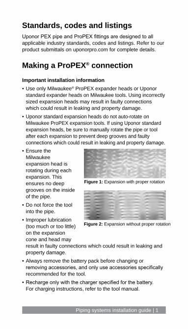
Making a ProPEX® connectionImportant installation information• Use only Milwaukee® ProPEX expander heads or Uponor
standard expander heads on Milwaukee tools. Using incorrectly sized expansion heads may result in faulty connections which could result in leaking and property damage.
• Uponor standard expansion heads do not auto-rotate on Milwaukee ProPEX expansion tools. If using Uponor standard expansion heads, be sure to manually rotate the pipe or tool after each expansion to prevent deep grooves and faulty connections which could result in leaking and property damage.
Standards, codes and listingsUponor PEX pipe and ProPEX fittings are designed to all applicable industry standards, codes and listings. Refer to our product submittals on uponorpro.com for complete details.
Figure 1: Expansion with proper rotation
Figure 2: Expansion without proper rotation
• Ensure the Milwaukee expansion head is rotating during each expansion. This ensures no deep grooves on the inside of the pipe.
• Do not force the tool into the pipe.
• Improper lubrication (too much or too little) on the expansion cone and head may result in faulty connections which could result in leaking and property damage.
• Always remove the battery pack before changing or removing accessories, and only use accessories specifically recommended for the tool.
• Recharge only with the charger specified for the battery. For charging instructions, refer to the tool manual.

2 | uponorpro.com
• To reduce risk of injury and damage, never immerse the tool, battery pack or charger in liquid or allow a liquid to flow inside the tool.
• Always unplug the charger and remove the battery pack from the charger or tool before performing any maintenance. Never disassemble the tool, battery pack or charger.
• Contact Milwaukee Tool at 800.SAWDUST (800.729.3878) for all service and repair work.
Figure 4: Milwaukee M18™ ProPEX expansion tool for ⅜" to 1½" pipe
Figure 3: Milwaukee M12™ ProPEX expansion tool for ⅜" to 1" pipe

Piping systems installation guide | 3
Figure 5: Square cut the pipe. Figure 6: Place the ProPEX ring over the end of the pipe.
Figure 7: Expand the pipe and ring until it reaches the collar. Then complete a minimum of one more expansion.
Figure 8: Insert the ProPEX fitting fully to the pipe stop.
ProPEX connections with Milwaukee toolsRefer to the following steps to make ½" to 3" ProPEX connections. Each expansion tool features slight differences in operation. Use the Milwaukee M12 ProPEX expansion tool for ½" to 1" connections; use the Milwaukee M18 ProPEX expansion tool for ½" to 1½" connections.
1 2
3 4
Making ⅜" ProPEX connectionsWhen making a ⅜" ProPEX connection, expand the ring once on each side to properly fit over the piping. Refer to the following instructions to make a ⅜" ProPEX connection.1. Square cut the PEX piping perpendicular to the length of
the piping. Remove all excess material or burrs that might affect the fitting connection.
2. Expand each side of the ring once.3. Slide the expanded ring over the end of the piping. Extend
the end of the ring over the end of the piping no more than 11⁄1616" (1mm).
4. After the ring is on the piping, continue with the regular steps for making a proper connection with your specific tool.
4 | uponorpro.com
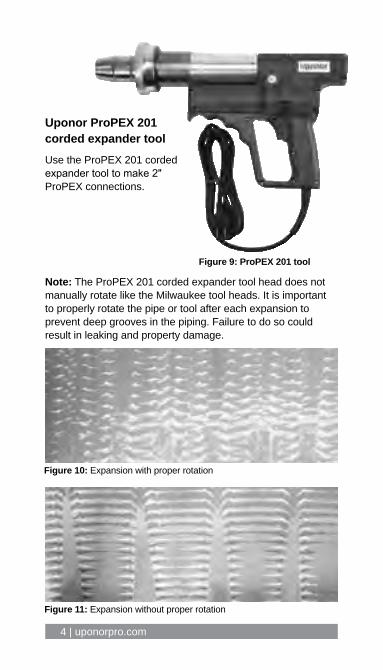
Uponor ProPEX 201 corded expander toolUse the ProPEX 201 corded expander tool to make 2" ProPEX connections.
Figure 10: Expansion with proper rotation
Figure 11: Expansion without proper rotation
Note: The ProPEX 201 corded expander tool head does not manually rotate like the Milwaukee tool heads. It is important to properly rotate the pipe or tool after each expansion to prevent deep grooves in the piping. Failure to do so could result in leaking and property damage.
Figure 9: ProPEX 201 tool
Piping systems installation guide | 5
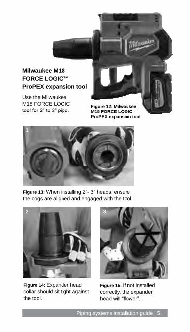
Figure 13: When installing 2"- 3" heads, ensure the cogs are aligned and engaged with the tool.
Figure 14: Expander head collar should sit tight against the tool.
Figure 15: If not installed correctly, the expander head will “flower”.
Milwaukee M18 FORCE LOGIC™ ProPEX expansion toolUse the Milwaukee M18 FORCE LOGIC tool for 2" to 3" pipe.
1
2 3
Figure 12: Milwaukee M18 FORCE LOGIC ProPEX expansion tool
6 | uponorpro.com
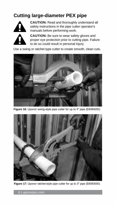
Cutting large-diameter PEX pipe
Figure 16: Uponor swing-style pipe cutter for up to 4" pipe (E6084000)
Figure 17: Uponor ratchet-style pipe cutter for up to 3" pipe (E6083000)
CAUTION: Read and thoroughly understand all safety instructions in the pipe cutter operator's manuals before performing work.CAUTION: Be sure to wear safety gloves and proper eye protection prior to cutting pipe. Failure to do so could result in personal injury.
Use a swing or ratchet-type cutter to create smooth, clean cuts.
Piping systems installation guide | 7
Troubleshooting a ProPEX connection1. Ensure the expansion tool is properly maintained and in
good working condition.2. Ensure the expansion head is securely tightened onto
the tool; frequently check that the head remains securely tightened throughout the installation process.
3. Ensure the segment fingers are not bent.4. Remove excess grease.5. Check the fitting for damage. Nicks and gouges will cause
the fitting to leak.6. Make sure the last expansion is not held in the expanded
position before inserting the fitting.7. Ensure proper rotation is occurring.8. If a ProPEX ring slips, make sure that the outer pipe surface
is clean and clear of any liquids. Inspect that the stop edge is present on the ProPEX ring.
Cold-weather expansionsTemperatures affect the time required for the piping and ring to shrink onto the fitting. Follow the below steps when making expansions in cold weather.1. Warming the ProPEX fittings and ProPEX rings reduces
contraction time. Put fittings and rings in your pockets prior to installation to keep them warm.
2. Make ProPEX connections at temperatures above 5°F (-15°C).
3. Fewer expansions are necessary in temperatures below 40°F (4.4°C).
4. Perform a test connection for each pipe size when temperatures differ from day to day, keeping note of the number of expansions to make a snug-fitting connection.

8 | uponorpro.com
Verifying ProPEX connectionsEnsure the ProPEX ring is tight against the fitting shoulder.
Table 1: Minimum PEX cut length
Pipe size Minimum cut length of pipe
½" 2" (51mm)
⅝" 2½" (64mm)
¾" 3" (76mm)
1" 3½" (89mm)
1¼" 4½" (114mm)
1½" 4½" (114mm)
2" 6" (152mm)
2½" 7½" (191mm)
3" 9" (229mm)
Cut length of pipe
Figure 20: Minimum PEX length between fittings
Figure 19: Tee shoulder
Minimum distance between fittingsUponor requires a minimum distance between ProPEX fittings to avoid damaging the fittings during installation and to protect against elevated stress on the pipe and fittings.
Figure 18: Coupling shoulder

Piping systems installation guide | 9
Bending PEX
Radius
Figure 21: Bend radius
2 x O.D.
Figure 22: Correct bending Figure 23: Incorrect bending
Uponor PEX bend radiusThe minimum bend radius of Uponor AquaPEX pipe is six times the outside diameter. Bend supports are available for ⅜", ½", ¾" and 1" piping and may be used to facilitate 90-degree rigid bends. Use large-diameter PVC conduit to facilitate 90-degree bends in larger-diameter Uponor PEX piping. Table 2: Bending Uponor PEX Pipe size
Pipe O.D.
Min. bend radius 2 x O.D.
½" 0.625" 3¾" (95mm)
1¼" (32mm)
¾" 0.875" 5¼" (133mm)
1¾" (44mm)
1" 1.125" 6¾" (171mm)
2¼" (57mm)
To alleviate stress on ProPEX connections and fittings, do not change direction immediately after a ProPEX connection.
Uponor recommends a minimum of two times the outside diameter (O.D.) of the pipe as the minimum distance before changing direction; however, it is up to the installer to use best judgment. See Figures 22 and 23 for guidance.Note: When a proper bend is not possible, use a ProPEX elbow.Note: Uponor recommends the use of elbows in sizes 1¼" and larger for directional changes unless adequate space is available for a proper bend.
10 | uponorpro.com
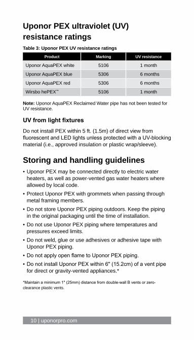
Uponor PEX ultraviolet (UV) resistance ratingsTable 3: Uponor PEX UV resistance ratings
Product Marking UV resistance
Uponor AquaPEX white 5106 1 month
Uponor AquaPEX blue 5306 6 months
Uponor AquaPEX red 5306 6 months
Wirsbo hePEX™ 5106 1 month
Note: Uponor AquaPEX Reclaimed Water pipe has not been tested for UV resistance.
UV from light fixturesDo not install PEX within 5 ft. (1.5m) of direct view from fluorescent and LED lights unless protected with a UV-blocking material (i.e., approved insulation or plastic wrap/sleeve).
Storing and handling guidelines• Uponor PEX may be connected directly to electric water
heaters, as well as power-vented gas water heaters where allowed by local code.
• Protect Uponor PEX with grommets when passing through metal framing members.
• Do not store Uponor PEX piping outdoors. Keep the piping in the original packaging until the time of installation.
• Do not use Uponor PEX piping where temperatures and pressures exceed limits.
• Do not weld, glue or use adhesives or adhesive tape with Uponor PEX piping.
• Do not apply open flame to Uponor PEX piping.• Do not install Uponor PEX within 6" (15.2cm) of a vent pipe
for direct or gravity-vented appliances.*
*Maintain a minimum 1" (25mm) distance from double-wall B vents or zero-clearance plastic vents.
Piping systems installation guide | 11
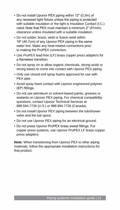
• Do not install Uponor PEX piping within 12" (0.3m) of any recessed light fixture unless the piping is protected with suitable insulation or the light is Insulation Contact (I.C.) rated. Note that PEX must maintain a minimum 2" (51mm) clearance unless insulated with a suitable insulation.
• Do not solder, braze, weld or fusion-weld within 18" (45.7cm) of any Uponor PEX piping in the same water line. Make any heat-related connections prior to making the ProPEX connection.
• Use ProPEX lead-free (LF) brass copper press adapters for a flameless transition.
• Do not spray on or allow organic chemicals, strong acids or strong bases to come into contact with Uponor PEX piping.
• Only use closed-cell spray foams approved for use with PEX pipe.
• Avoid spray foam contact with Uponor engineered polymer (EP) fittings.
• Do not use petroleum or solvent-based paints, greases or sealants on Uponor PEX piping. For chemical compatibility questions, contact Uponor Technical Services at 888.594.7726 (U.S.) or 888.994.7726 (Canada).
• Do not install Uponor PEX piping between the tub/shower valve and the tub spout.
• Do not use Uponor PEX piping for an electrical ground. • Do not press Uponor ProPEX brass sweat fittings. For
copper press systems, use Uponor ProPEX LF brass copper press adapters.
Note: When transitioning from Uponor PEX to other piping materials, follow the appropriate installation instructions for that product.
12 | uponorpro.com
Supporting Uponor PEX pipe
General notes• Use copper tube size (CTS) clamps/supports
• Use clamps/supports designed for plastic pipe
• Follow local code requirements
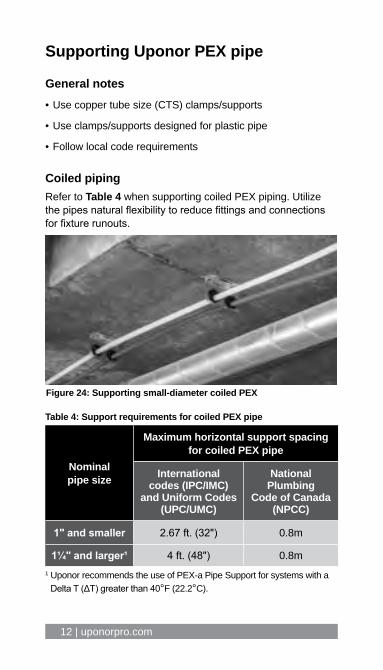
Coiled pipingRefer to Table 4 when supporting coiled PEX piping. Utilize the pipes natural flexibility to reduce fittings and connections for fixture runouts.
Table 4: Support requirements for coiled PEX pipe
Nominal pipe size
Maximum horizontal support spacing for coiled PEX pipe
International codes (IPC/IMC)
and Uniform Codes (UPC/UMC)
National Plumbing
Code of Canada (NPCC)
1" and smaller 2.67 ft. (32") 0.8m
1¼" and larger¹ 4 ft. (48") 0.8m1 Uponor recommends the use of PEX-a Pipe Support for systems with a
Delta T (ΔT) greater than 40°F (22.2°C).
Figure 24: Supporting small-diameter coiled PEX

Piping systems installation guide | 13
Figure 25: In-wall supports for multiport tees
Figure 26: Supporting multiport tees on wood I-joists
Figure 27: Supporting multiport tees on open-web wood trusses
Supporting Uponor multiport tees
Wood I-joist
Commercial multiport teewith mounting clips (included)
Multiport tee
6"max.
Commerical mulitiport teewith mounting clips (included)
6"max.
Open-web truss
Multiport tee
Plastic piping support
Commercialmultiporttee with mountingclips(included)
Blocking(typical)
6" max.
6" max.

14 | uponorpro.com
Figure 28: Supporting multiport tees in suspended applications
Figure 29: Supporting multiport tees on drywall grid
6"max.
Multiport tee
CTS hanger
6"max.
Grid hanger wire
CTS clamp
Drywall grid
Drywall cross tee
Piping systems installation guide | 15
StrappingSupport Uponor PEX pipe by approved materials/methods only, including:• Tube talons• Clamps and hangers (i.e., loop or clevis hangers)• Stand-off brackets
Isolate piping from other mechanical, electrical and plumbing (MEP) systems by means of insulation or stand-off brackets. Uponor does not recommend strapping PEX pipe directly to waste and vent piping. Always follow local code.
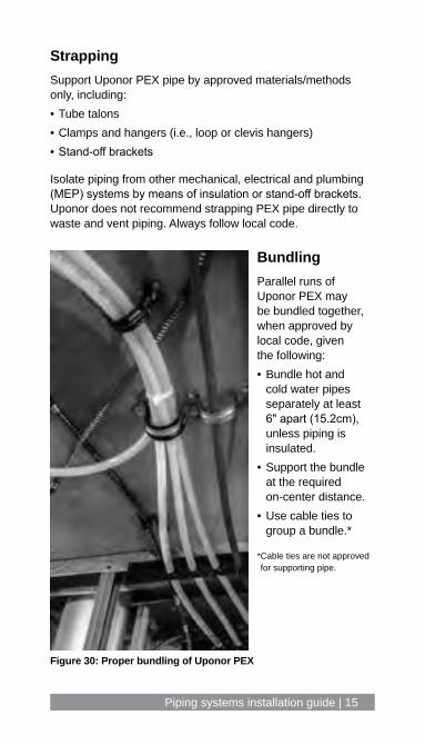
BundlingParallel runs of Uponor PEX may be bundled together, when approved by local code, given the following:• Bundle hot and
cold water pipes separately at least 6" apart (15.2cm), unless piping is insulated.
• Support the bundle at the required on-center distance.
• Use cable ties to group a bundle.*
* Cable ties are not approved for supporting pipe.
Figure 30: Proper bundling of Uponor PEX

16 | uponorpro.com
Main/corridor straight-length piping Per ICC-ES PMG 1006, using Uponor PEX-a Pipe Support allows extended support spacing up to 8 ft. (2.4m). Refer to Table 5.Note: To minimize sagging and expansion/contraction, Uponor recommends using PEX-a Pipe Support for all main/corridor piping systems with ΔTs greater than 40°F (22.2°C).
Table 5: Horizontal support requirements with PEX-a Pipe Support
System type Max. support spacing with PEX-a Pipe Support
Fixed points
ΔT less than or equal to 40°F (22.2°C) (e.g., domestic cold water, chilled water)1
8 ft. (2.4m) Not required
ΔT greater than 40°F (22.2°C) (e.g., domestic hot water, domestic hot water recirculation, heating hot water)1
8 ft. (2.4m) with clamps every 32 ft. (9.7m) max.2
See Table 6
1 These system examples are merely a suggestion of system types. The deciding factor is the temperature differential (Delta T) at the time of system start up.
2 Fittings that are 1½" and smaller require support within 12" (0.3m) to prevent sagging. It is acceptable practice to support the fittings from their respective branch pipes.
Definitions Use the below definitions with Tables 5 and 6.
Delta T (ΔT) – Difference between ambient air temperature and average system operating temperature.
Support – Loop, clevis, strut or similar that provide support for the piping system.
Clamps – Strut clamps or split-ring clamps that both support the piping system and limit its movement.
Fixed point – A support with clamps that is braced to the structure to prevent its movement due to expansion and/or contraction of the piping system. See Figure 31.

Piping systems installation guide | 17
Expansion and contraction To help minimize expansion and contraction in long, continuous piping runs with ΔTs greater than 40°F (22.2°C), use fixed points in conjunction with PEX-a Pipe Support and clamps. Refer to Table 6 for requirements.
Table 6: Fixed-point requirements
Length of straight-piping run # of fixed points* Fixed-point spacing
0 – 63 ft. (0 – 19.2m) 0 N/A
64 – 128 ft. (19.5 – 39m) 1 Closest support with clamps to center
129 – 192 ft. (39.3 – 58.5m) 2
Min. 64 ft. apart (19.5m)193 – 256 ft. (58.8 – 78m) 3
257 – 320 ft. (78.3 – 97.5m) 4
*Pipes 1" and smaller do not require fixed points.
Figure 31: Supporting PEX with PEX-a Pipe Support
18 | uponorpro.com
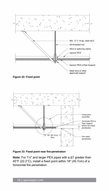
Min. ⅞" x 14-ga. steel strut
All-threaded rod
Strut or split-ring clamp
Uponor PEX
Uponor PEX-a Pipe Support
Steel strut or other approved support
Fixed point assembly
Terminate PEX-a Pipe Supportbefore fire-rated penetration
Fire-rated penetration
18" (45.7cm) Max.
Figure 32: Fixed point
Figure 33: Fixed point near fire-penetration
Note: For 1¼" and larger PEX pipes with a ΔT greater than 40°F (22.2°C), install a fixed point within 18" (45.7cm) of a horizontal fire penetration.

Piping systems installation guide | 19
Installing Uponor PEX-a Pipe Support• Use full lengths and minimize cutting when possible.• Deburr sharp edges if cutting is required.• Maintain minimum distance to fittings according to Table 7.• Secure included straps according to Figures 35-38.
Table 7: Minimum distance to fittings for PEX-a Pipe Support
Nominal pipe size Distance to fitting “A”
½" 1¼" (32mm)
¾" 1¾" (44mm)
1" 2¼" (57mm)
1¼" 2¾" (70mm)
1½" 3" (76mm)
2" 4" (102mm)
2½" 5" (127mm)
3" 6" (152mm)
Figure 34: Minimum distance to fitting
A

20 | uponorpro.com
Strapping PEX-a Pipe Support
Figure 35: Strapping for systems using strut-type clamps or equivalent
Figure 36: Strapping for systems using clevis or loop-type hangers or equivalent
Figure 37: Strapping for overlaps
Strap within 1" of hanger
Strap at mid-span
Clevis hanger
PEX-a Pipe Support
Strap at mid-spanStrut clampPEX-a Pipe Support
6" min.overlap
Strap
Use the included stainless-steel straps to secure PEX-a Pipe Support to the PEX pipe. If the straps are misplaced, use a stainless-steel strap with a minimum 300-lb. rating that is also rated for the application (e.g., temperature, UV).
Piping systems installation guide | 21
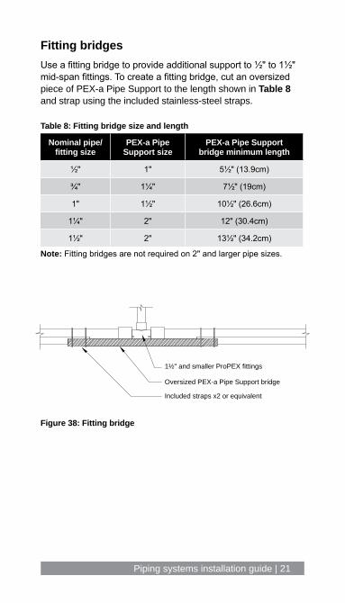
Fitting bridgesUse a fitting bridge to provide additional support to ½" to 1½" mid-span fittings. To create a fitting bridge, cut an oversized piece of PEX-a Pipe Support to the length shown in Table 8 and strap using the included stainless-steel straps.
Table 8: Fitting bridge size and length
Nominal pipe/fitting size
PEX-a Pipe Support size
PEX-a Pipe Support bridge minimum length
½" 1" 5½" (13.9cm)
¾" 1¼" 7½" (19cm)
1" 1½" 10½" (26.6cm)
1¼" 2" 12" (30.4cm)
1½" 2" 13½" (34.2cm)
Note: Fitting bridges are not required on 2" and larger pipe sizes.
1½" and smaller ProPEX fittings
Oversized PEX-a Pipe Support bridge
Included straps x2 or equivalent
Figure 38: Fitting bridge
22 | uponorpro.com
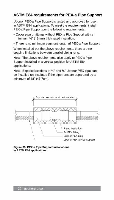
Rated insulationProPEX fittingUponor PEX pipeUponor PEX-a Pipe Support
Exposed section must be insulated
Figure 39: PEX-a Pipe Support installations in ASTM E84 applications
ASTM E84 requirements for PEX-a Pipe SupportUponor PEX-a Pipe Support is tested and approved for use in ASTM E84 applications. To meet the requirements, install PEX-a Pipe Support per the following requirements:• Cover pipe or fittings without PEX-a Pipe Support with a
minimum ½" (13mm) thick rated insulation.• There is no minimum segment length of PEX-a Pipe Support.When installed per the above requirements, there are no spacing limitations between parallel piping runs.Note: The above requirements also apply to PEX-a Pipe Support installed in a vertical position for ASTM E84 applications.Note: Exposed sections of ½" and ¾" Uponor PEX pipe can be installed un-insulated if the pipe runs are separated by a minimum of 18" (45.7cm).
Piping systems installation guide | 23
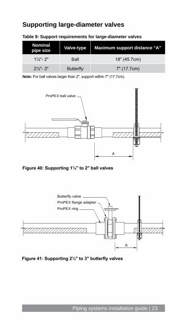
Supporting large-diameter valvesTable 9: Support requirements for large-diameter valves
Nominal pipe size Valve-type Maximum support distance “A”
1¼"- 2" Ball 18" (45.7cm)
2½"- 3" Butterfly 7" (17.7cm)Note: For ball valves larger than 2", support within 7" (17.7cm).
ProPEX ball valve
A
Butterfly valveProPEX flange adapterProPEX ring
A
Figure 40: Supporting 1¼" to 2" ball valves
Figure 41: Supporting 2½" to 3" butterfly valves
24 | uponorpro.com
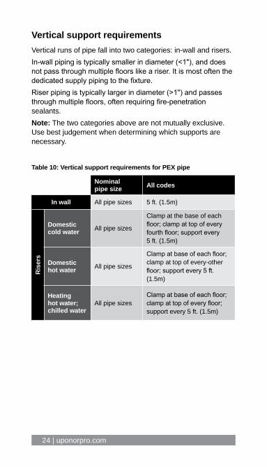
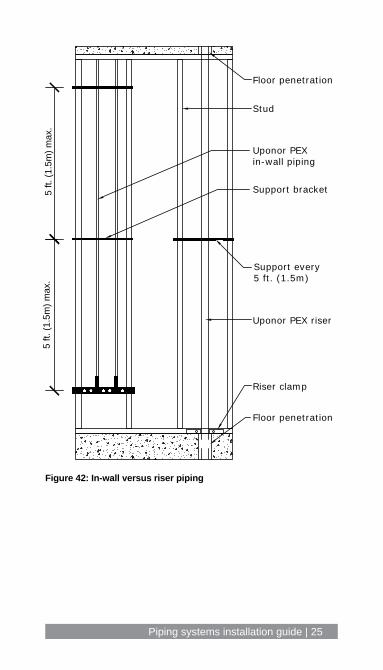
Vertical support requirementsVertical runs of pipe fall into two categories: in-wall and risers.In-wall piping is typically smaller in diameter (<1"), and does not pass through multiple floors like a riser. It is most often the dedicated supply piping to the fixture. Riser piping is typically larger in diameter (>1") and passes through multiple floors, often requiring fire-penetration sealants. Note: The two categories above are not mutually exclusive. Use best judgement when determining which supports are necessary.
Table 10: Vertical support requirements for PEX pipe
Nominal pipe size All codes
In wall All pipe sizes 5 ft. (1.5m)
Rise
rs
Domestic cold water All pipe sizes
Clamp at the base of each floor; clamp at top of every fourth floor; support every 5 ft. (1.5m)
Domestic hot water All pipe sizes
Clamp at base of each floor; clamp at top of every-other floor; support every 5 ft. (1.5m)
Heating hot water; chilled water
All pipe sizesClamp at base of each floor; clamp at top of every floor; support every 5 ft. (1.5m)
Piping systems installation guide | 25
Figure 42: In-wall versus riser piping
5 ft.
(1.5
m) m
ax.
5 ft.
(1.5
m) m
ax.
Floor penetration
Riser clamp
Uponor PEX riser
Support every 5 ft. (1.5m)
Stud
Floor penetration
Uponor PEXin-wall piping
Support bracket

26 | uponorpro.com
Figure 43: Riser clamp detail
Table 11: Distance to clamps
Nominal pipe size 2 x O.D.
½" 1¼" (32mm)
⅝" 1½" (38mm)
¾" 1¾" (44mm)
1" 2¼" (57mm)
1¼" 2¾" (70mm)
1½" 3¼" (83mm)
2" 4¼" (108mm)
2½" 4¾" (133mm)
3" 6¼" (159mm)
3½" 7¼" (184mm)
4" 8¼" (210mm)
2 x
O.D
.
ProPEX fitting
ProPEX ring
Uponor PEX pipe
CTS riser clamp
Riser clampsTo prevent damage to ProPEX fittings, Uponor recommends the following minimum distances between riser clamps and ProPEX fittings.

Piping systems installation guide | 27
ProPEX EP tee
Riser clamp required at the top of each floor
Riser clamp required at the top of each floor
Riser clamp required at the base of each floor
Riser clamp required at the top of each floor
Riser clamp required at the base of each floor
Refer to appropriate fire assembly listing for penetration requirements
ProPEX EP tee
Plastic bend support
Plastic bend support
ProPEX transition fittingfor valve assembly
Fan Coil Unit (FCU)
FCU
Note: Other terminal units, such as heat pumps, radiators, VAV boxes and chilled beams can be suppliedthrough similar means.
PEX-a Pipe Support
Wirsbo hePEX hot and chilled water supply and return risersAppropriate firestop material (must be Wirsbo hePEX compatible)
Mid-story guide required between each floor
Wall-framing member
Mid-story guide required between each floor
Use appropriate wall assembly per code
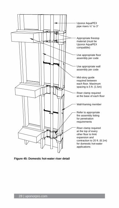
RisersVertical piping runs must comply with support spacing as defined by code. Best practice is to use the floor/ceiling assembly as a fixed point for controlling expansion and contraction by means of riser clamps.
Figure 44: Hydronic piping riser detail
28 | uponorpro.com
Figure 45: Domestic hot-water riser detail
Uponor AquaPEXpipe risers ½" to 3"
Appropriate firestopmaterial (must beUponor AquaPEXcompatible)
Use appropriate floorassembly per code
Use appropriate wallassembly per code
Mid-story guiderequired betweeneach floor. Maximumspacing is 5 ft. (1.5m)
Riser clamp requiredat the base of each floor
Wall-framing member
Refer to appropriatefire assembly listingfor penetrationrequirements
Riser clamp requiredat the top of everyother floor to limitexpansion andcontraction to 20 ft. (6.1m)for domestic hot-waterapplications

Piping systems installation guide | 29
United States — ASTM E84
Minimum 18"Clamp
½" through ¾" Uponor PEX pipe
No limitation Clamp
Minimum ½" 25/50rated insulation
½" through 3" Uponor PEX pipe
Figure 46: QAI P321-1
Guidelines: ½" through ¾" (uninsulated) Limitations: Adjacent runs shall be located at least 18" (45.7cm) apart.
Figure 47: QAI P321-1
Guidelines: ½" through 3" (insulated) Limitations: ½" minimum thickness insulation as specified in Table 12.
No limitation Clamp
½" through 3" Uponor PEX pipe
Uponor PEX-aPipe Support
Figure 48: QAI P321-2
Guidelines: ½" through 3" (PEX-a Pipe Support) Limitations: Pipe or fitting sections without PEX-a Pipe Support must be covered with a rated insulation per Table 12. There is no minimum length of PEX-a Pipe Support segments.
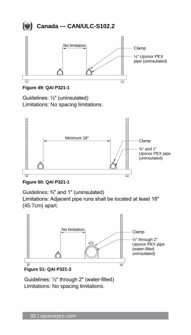
Fire-resistant constructionThe following requirements are for Uponor products installed in return-air plenum spaces.
30 | uponorpro.com
½" Uponor PEXpipe (uninsulated)
ClampNo limitation
¾" and 1"Uponor PEX pipe(uninsulated)
ClampMinimum 18"
Figure 49: QAI P321-1
Guidelines: ½" (uninsulated) Limitations: No spacing limitations.
Figure 50: QAI P321-1
Guidelines: 33⁄44" and 1" (uninsulated) Limitations: Adjacent pipe runs shall be located at least 18" (45.7cm) apart.
½" through 2"Uponor PEX pipe(water-filled,uninsulated)
ClampNo limitation
Figure 51: QAI P321-3
Guidelines: ½" through 2" (water-filled) Limitations: No spacing limitations.
Canada — CAN/ULC-S102.2
Piping systems installation guide | 31
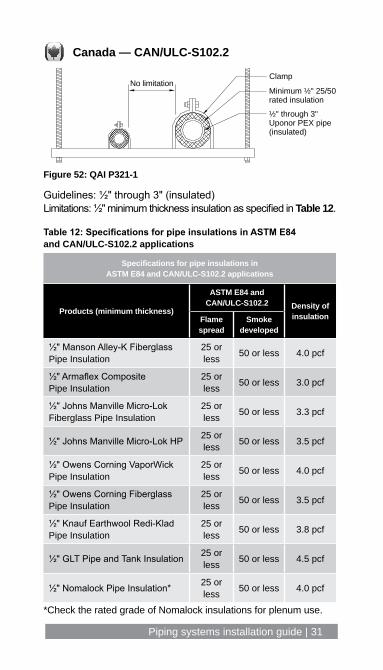
Figure 52: QAI P321-1
Guidelines: ½" through 3" (insulated) Limitations: ½" minimum thickness insulation as specified in Table 12.
Canada — CAN/ULC-S102.2
No limitationClamp
½" through 3" Uponor PEX pipe(insulated)
Minimum ½" 25/50rated insulation
Table 12: Specifications for pipe insulations in ASTM E84 and CAN/ULC-S102.2 applications
Specifications for pipe insulations in ASTM E84 and CAN/ULC-S102.2 applications
Products (minimum thickness)
ASTM E84 and CAN/ULC-S102.2 Density of
insulationFlame spread
Smoke developed
½" Manson Alley-K Fiberglass Pipe Insulation
25 or less 50 or less 4.0 pcf
½" Armaflex Composite Pipe Insulation
25 or less 50 or less 3.0 pcf
½" Johns Manville Micro-Lok Fiberglass Pipe Insulation
25 or less 50 or less 3.3 pcf
½" Johns Manville Micro-Lok HP 25 or less 50 or less 3.5 pcf
½" Owens Corning VaporWick Pipe Insulation
25 or less 50 or less 4.0 pcf
½" Owens Corning Fiberglass Pipe Insulation
25 or less 50 or less 3.5 pcf
½" Knauf Earthwool Redi-Klad Pipe Insulation
25 or less 50 or less 3.8 pcf
½" GLT Pipe and Tank Insulation 25 or less 50 or less 4.5 pcf
½" Nomalock Pipe Insulation* 25 or less 50 or less 4.0 pcf
*Check the rated grade of Nomalock insulations for plenum use.

32 | uponorpro.com
ASTM E814 and CAN/ULC S115 listingsTable 13: Fire assemblies per manufacturer
Assembly types
Manufacturer
3M™ Hilti® RectorSeal® STI
Wall Floor/ceiling Wall Floor/ceiling Wall Floor/ceiling Wall Floor/ceiling
Woo
d-st
ud/s
teel
-stu
d as
sem
blie
s
1-ho
ur
PHV-120-04 F-C-2039 W-L-2186 F-C-2081 W-L-2342 F-C-2298 F-C-2319 F-C-2032
PHV-120-11 F-C-2240 W-L-2235 F-C-2230 W-L-2262 F-C-8015 W-L-2100 F-C-2252
W-L-2091 F-C-2343 W-L-2466 F-C-2310 W-L-2373 F-C-2329 W-L-2144 F-C-2319
W-L-2146 F-C-2344 W-L-2474 F-C-2334 W-L-2430 F-C-2212 W-L-2241 F-E-2003
W-L-2173 F-C-2391 W-L-2480 F-C-8038 W-L-2526 F-E-2007 W-L-2242 F-C-8021
W-L-2448 F-E-2002 W-L-2537 F-C-8044 W-L-2121 F-C-2221 W-L-2423 F-C-8029
W-L-2483 F-E-2012 W-L-2467 W-L-2209 F-C-2385 W-L-2508 F-E-8003
W-L-2543 F-E-2040 W-L-5224 W-L-2528 W-L-2548 F-C-8045
W-L-2547 PHV-120-04 W-L-2402 W-L-2549 F-E-8010
W-L-2299 PHV-120-11 W-L-2638 W-L-7193
PV-60-02 W-L-2639 F-C-8021
W-L-2007 F-C-8029
W-L-2170 W-L-5290
W-L-2287 W-L-2631
W-L-2457
W-L-2524
W-L-2594
W-L-2595Note: This table is not meant to address every compatible fire assembly or firestop manufacturer. It is the end user’s responsibility to ensure the fire assembly documentation being used is approved and current for the specific application. Please refer to the respective manufacturer’s website for detailed listing information.
= ASTM E814 and CAN/ULC S115 = ASTM E814 only

Piping systems installation guide | 33
ASTM E814 and CAN/ULC S115 listingsTable 13: Fire assemblies per manufacturer
Assembly types
Manufacturer
3M™ Hilti® RectorSeal® STI
Wall Floor/ceiling Wall Floor/ceiling Wall Floor/ceiling Wall Floor/ceiling
Woo
d-st
ud/s
teel
-stu
d as
sem
blie
s
1-ho
ur
PHV-120-04 F-C-2039 W-L-2186 F-C-2081 W-L-2342 F-C-2298 F-C-2319 F-C-2032
PHV-120-11 F-C-2240 W-L-2235 F-C-2230 W-L-2262 F-C-8015 W-L-2100 F-C-2252
W-L-2091 F-C-2343 W-L-2466 F-C-2310 W-L-2373 F-C-2329 W-L-2144 F-C-2319
W-L-2146 F-C-2344 W-L-2474 F-C-2334 W-L-2430 F-C-2212 W-L-2241 F-E-2003
W-L-2173 F-C-2391 W-L-2480 F-C-8038 W-L-2526 F-E-2007 W-L-2242 F-C-8021
W-L-2448 F-E-2002 W-L-2537 F-C-8044 W-L-2121 F-C-2221 W-L-2423 F-C-8029
W-L-2483 F-E-2012 W-L-2467 W-L-2209 F-C-2385 W-L-2508 F-E-8003
W-L-2543 F-E-2040 W-L-5224 W-L-2528 W-L-2548 F-C-8045
W-L-2547 PHV-120-04 W-L-2402 W-L-2549 F-E-8010
W-L-2299 PHV-120-11 W-L-2638 W-L-7193
PV-60-02 W-L-2639 F-C-8021
W-L-2007 F-C-8029
W-L-2170 W-L-5290
W-L-2287 W-L-2631
W-L-2457
W-L-2524
W-L-2594
W-L-2595Note: This table is not meant to address every compatible fire assembly or firestop manufacturer. It is the end user’s responsibility to ensure the fire assembly documentation being used is approved and current for the specific application. Please refer to the respective manufacturer’s website for detailed listing information.
Manufacturer
= ASTM E814 and CAN/ULC S115 = ASTM E814 only

34 | uponorpro.com
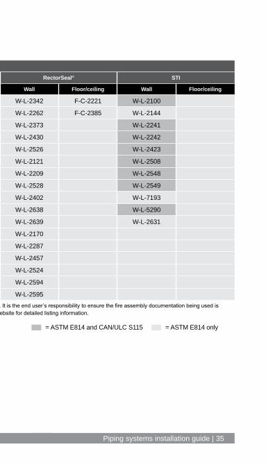
ASTM E814 and CAN/ULC S115 listingsTable 14: Fire assemblies per manufacturer
Assembly types
Manufacturer
3M™ Hilti® RectorSeal® STI
Wall Floor/ceiling Wall Floor/ceiling Wall Floor/ceiling Wall Floor/ceiling
Woo
d-st
ud/s
teel
-stu
d as
sem
blie
s
2-ho
ur
PHV-120-04 PHV-120-04 W-L-2186 F-C-2081 W-L-2342 F-C-2221 W-L-2100
PHV-120-11 PHV-120-11 W-L-2235 F-C-2310 W-L-2262 F-C-2385 W-L-2144
W-L-2090 W-L-2466 W-L-2373 W-L-2241
W-L-2091 W-L-2474 W-L-2430 W-L-2242
W-L-2146 W-L-2480 W-L-2526 W-L-2423
W-L-2448 W-L-2537 W-L-2121 W-L-2508
W-L-2483 W-L-2467 W-L-2209 W-L-2548
W-L-2543 W-L-5224 W-L-2528 W-L-2549
W-L-2547 W-L-2402 W-L-7193
W-L-2299 W-L-2638 W-L-5290
W-L-2639 W-L-2631
W-L-2170
W-L-2287
W-L-2457
W-L-2524
W-L-2594
W-L-2595Note: This table is not meant to address every compatible fire assembly or firestop manufacturer. It is the end user’s responsibility to ensure the fire assembly documentation being used is approved and current for the specific application. Please refer to the respective manufacturer’s website for detailed listing information.
= ASTM E814 and CAN/ULC S115 = ASTM E814 only
Piping systems installation guide | 3534 | uponorpro.com
ASTM E814 and CAN/ULC S115 listingsTable 14: Fire assemblies per manufacturer
Assembly types
Manufacturer
3M™ Hilti® RectorSeal® STI
Wall Floor/ceiling Wall Floor/ceiling Wall Floor/ceiling Wall Floor/ceiling
Woo
d-st
ud/s
teel
-stu
d as
sem
blie
s
2-ho
ur
PHV-120-04 PHV-120-04 W-L-2186 F-C-2081 W-L-2342 F-C-2221 W-L-2100
PHV-120-11 PHV-120-11 W-L-2235 F-C-2310 W-L-2262 F-C-2385 W-L-2144
W-L-2090 W-L-2466 W-L-2373 W-L-2241
W-L-2091 W-L-2474 W-L-2430 W-L-2242
W-L-2146 W-L-2480 W-L-2526 W-L-2423
W-L-2448 W-L-2537 W-L-2121 W-L-2508
W-L-2483 W-L-2467 W-L-2209 W-L-2548
W-L-2543 W-L-5224 W-L-2528 W-L-2549
W-L-2547 W-L-2402 W-L-7193
W-L-2299 W-L-2638 W-L-5290
W-L-2639 W-L-2631
W-L-2170
W-L-2287
W-L-2457
W-L-2524
W-L-2594
W-L-2595Note: This table is not meant to address every compatible fire assembly or firestop manufacturer. It is the end user’s responsibility to ensure the fire assembly documentation being used is approved and current for the specific application. Please refer to the respective manufacturer’s website for detailed listing information.
= ASTM E814 and CAN/ULC S115 = ASTM E814 only
36 | uponorpro.com
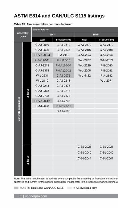
ASTM E814 and CAN/ULC S115 listingsTable 15: Fire assemblies per manufacturer
Assembly types
Manufacturer
3M™ Hilti® RectorSeal® STI HOLDRITE
Wall Floor/ceiling Wall Floor/ceiling Wall Floor/ceiling Wall Floor/ceiling Floor/ceiling
Con
cret
e as
sem
blie
s 2-ho
ur
C-AJ-2510 C-AJ-2510 C-AJ-2170 C-AJ-2170 W-J-2162 C-AJ-2628 W-J-2021 C-AJ-2031 F-A-2188
C-AJ-2536 C-AJ-2536 C-AJ-2407 C-AJ-2407 W-J-2122 F-A-2171 W-J-2043 C-AJ-2140 F-A-2221
PHV-120-04 F-A-2115 C-AJ-2647 C-AJ-2647 W-J-2180 C-AJ-2701 W-J-2076 C-AJ-2291 F-B-2042
PHV-120-11 PH-120-10 W-J-2207 C-AJ-2674 W-J-2025 C-AJ-2176 W-J-2077 F-A-2186 F-A-2269
C-AJ-2213 PHV-120-04 W-J-2229 F-B-2040 C-AJ-2628 F-A-2235 W-J-2232 F-A-2224 F-A-2222
C-AJ-2378 PHV-120-11 W-J-2206 F-B-2041 C-AJ-2679 F-A-2237 W-J-2233 F-A-2225 F-A-2037
W-J-2231 C-AJ-2076 W-J-5122 F-A-2142 C-AJ-2701 C-AJ-2494 W-J-5148 C-AJ-2586
W-J-2110 C-AJ-2213 W-J-2071 W-J-2295 C-AJ-2679 C-AJ-2586 C-AJ-5345
C-AJ-2213 C-AJ-2378 W-J-2296 C-AJ-2702 C-AJ-5345 C-BJ-2046
C-AJ-2378 C-AJ-2213 C-AJ-2702 C-BJ-2046
C-AJ-2738 C-AJ-2378 C-AJ-2176 W-J-2291
PHV-120-12 C-AJ-2738 C-AJ-2494
C-AJ-2698 PHV-120-12 W-J-2035
C-AJ-2698 W-J-2051
W-J-2142
W-J-2197
W-J-2220
W-J-2222
W-J-2224
W-J-2266
3-ho
ur
C-BJ-2028 C-BJ-2028 C-AJ-2119 C-AJ-2119 C-AJ-2671 C-AJ-2671 F-A-2176
C-BJ-2040 C-BJ-2040 C-AJ-2194 C-AJ-2194 C-AJ-5344 C-AJ-5344 F-A-2221
C-BJ-2041 C-BJ-2041 C-AJ-2622 C-AJ-2622 C-AJ-5346 C-AJ-5346 F-B-2042
C-AJ-2578 F-A-2269
F-A-2203 F-A-8034
F-A-2204 F-A-2222Note: This table is not meant to address every compatible fire assembly or firestop manufacturer. It is the end user’s responsibility to ensure the fire assembly documentation being used is approved and current for the specific application. Please refer to the respective manufacturer’s website for detailed listing information.
= ASTM E814 and CAN/ULC S115 = ASTM E814 only
Piping systems installation guide | 3736 | uponorpro.com
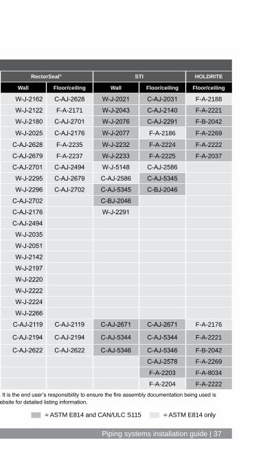
ASTM E814 and CAN/ULC S115 listingsTable 15: Fire assemblies per manufacturer
Assembly types
Manufacturer
3M™ Hilti® RectorSeal® STI HOLDRITE
Wall Floor/ceiling Wall Floor/ceiling Wall Floor/ceiling Wall Floor/ceiling Floor/ceiling
Con
cret
e as
sem
blie
s 2-ho
ur
C-AJ-2510 C-AJ-2510 C-AJ-2170 C-AJ-2170 W-J-2162 C-AJ-2628 W-J-2021 C-AJ-2031 F-A-2188
C-AJ-2536 C-AJ-2536 C-AJ-2407 C-AJ-2407 W-J-2122 F-A-2171 W-J-2043 C-AJ-2140 F-A-2221
PHV-120-04 F-A-2115 C-AJ-2647 C-AJ-2647 W-J-2180 C-AJ-2701 W-J-2076 C-AJ-2291 F-B-2042
PHV-120-11 PH-120-10 W-J-2207 C-AJ-2674 W-J-2025 C-AJ-2176 W-J-2077 F-A-2186 F-A-2269
C-AJ-2213 PHV-120-04 W-J-2229 F-B-2040 C-AJ-2628 F-A-2235 W-J-2232 F-A-2224 F-A-2222
C-AJ-2378 PHV-120-11 W-J-2206 F-B-2041 C-AJ-2679 F-A-2237 W-J-2233 F-A-2225 F-A-2037
W-J-2231 C-AJ-2076 W-J-5122 F-A-2142 C-AJ-2701 C-AJ-2494 W-J-5148 C-AJ-2586
W-J-2110 C-AJ-2213 W-J-2071 W-J-2295 C-AJ-2679 C-AJ-2586 C-AJ-5345
C-AJ-2213 C-AJ-2378 W-J-2296 C-AJ-2702 C-AJ-5345 C-BJ-2046
C-AJ-2378 C-AJ-2213 C-AJ-2702 C-BJ-2046
C-AJ-2738 C-AJ-2378 C-AJ-2176 W-J-2291
PHV-120-12 C-AJ-2738 C-AJ-2494
C-AJ-2698 PHV-120-12 W-J-2035
C-AJ-2698 W-J-2051
W-J-2142
W-J-2197
W-J-2220
W-J-2222
W-J-2224
W-J-2266
3-ho
ur
C-BJ-2028 C-BJ-2028 C-AJ-2119 C-AJ-2119 C-AJ-2671 C-AJ-2671 F-A-2176
C-BJ-2040 C-BJ-2040 C-AJ-2194 C-AJ-2194 C-AJ-5344 C-AJ-5344 F-A-2221
C-BJ-2041 C-BJ-2041 C-AJ-2622 C-AJ-2622 C-AJ-5346 C-AJ-5346 F-B-2042
C-AJ-2578 F-A-2269
F-A-2203 F-A-8034
F-A-2204 F-A-2222Note: This table is not meant to address every compatible fire assembly or firestop manufacturer. It is the end user’s responsibility to ensure the fire assembly documentation being used is approved and current for the specific application. Please refer to the respective manufacturer’s website for detailed listing information.
= ASTM E814 and CAN/ULC S115 = ASTM E814 only

38 | uponorpro.com
Below-grade installationUponor PEX piping and ProPEX fittings (EP and LF brass) are all approved for burial directly in soil. Refer to Figures 53 and 54 for proper trench preparation. Always follow local code when burying Uponor PEX pipe as some jurisdictions require additional sleeving and protection.
Uponor PEX piping
Undisturbed soil
Excavation level
Uponor PEX piping
Undisturbed soilFill levelExcavation level
Figure 53: Good soil conditions
Figure 54: Poor soil conditions
Piping systems installation guide | 39
Figure 55: In-slab installation
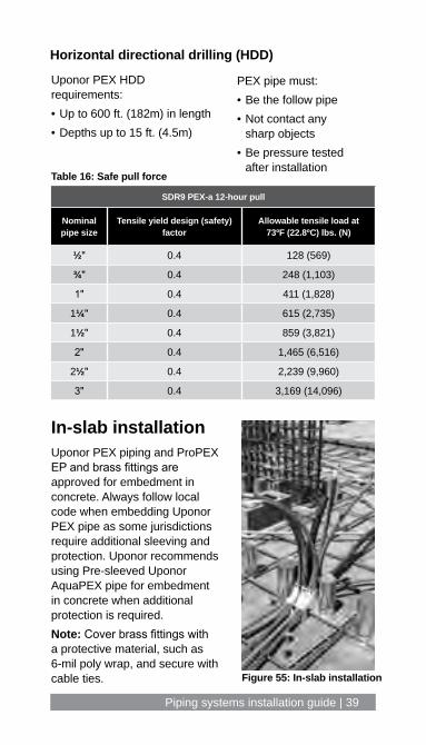
In-slab installationUponor PEX piping and ProPEX EP and brass fittings are approved for embedment in concrete. Always follow local code when embedding Uponor PEX pipe as some jurisdictions require additional sleeving and protection. Uponor recommends using Pre-sleeved Uponor AquaPEX pipe for embedment in concrete when additional protection is required.Note: Cover brass fittings with a protective material, such as 6-mil poly wrap, and secure with cable ties.
PEX pipe must:• Be the follow pipe• Not contact any
sharp objects• Be pressure tested
after installationTable 16: Safe pull force
SDR9 PEX-a 12-hour pull
Nominal pipe size
Tensile yield design (safety) factor
Allowable tensile load at 73ºF (22.8ºC) lbs. (N)
½" 0.4 128 (569)
¾" 0.4 248 (1,103)
1" 0.4 411 (1,828)
1¼" 0.4 615 (2,735)
1½" 0.4 859 (3,821)
2" 0.4 1,465 (6,516)
2½" 0.4 2,239 (9,960)
3" 0.4 3,169 (14,096)
Uponor PEX HDD requirements:• Up to 600 ft. (182m) in length• Depths up to 15 ft. (4.5m)
Horizontal directional drilling (HDD)

40 | uponorpro.com
Pressure testing
Residential applications1. Pressurize system to 25 psi (1.7 bar) above working
pressure or 100 psi (6.9 bar).2. Test in accordance with local code.
Commercial applications1. Visually confirm all connections are properly made per
Uponor installation guidelines. 2. Ensure that all components, fixtures and equipment not
rated for the test pressure are isolated from the test system. 3. Ensure that all other thermoplastic piping materials are
isolated from the test system. 4. Fill the system with potable water, air or a mixture of both.5. Condition the system to 1.5 times the required test pressure
for 30 minutes. This will require constant pumping or cycling the valve and compressor to maintain a pressure of 1.5 times the test pressure. If cycling the valve and compressor, apply additional pressure once the psi has dropped 10 psi (0.7 bar).
6. After conditioning the system for 30 minutes, quickly relieve excess pressure by opening the valve. Close the valve when the system has reached the desired test pressure.
Note: Uponor recommends a test pressure of 80 psi (5.5 bar) (unless local code dictates higher pressures).
7. Once the valve is closed, confirm a slight rise in pressure 3 to 6 psi (0.2 to 0.4 bar). This increase will occur as the pipe’s I.D. is shrinking from its conditioned state to equalize at the lower pressure.
8. Visually check for leakage and monitor the pressure for the duration specified by local code. (A typical pressure test can range from 2 to 24 hours).
9. If there is no reduction in pressure, the system is regarded as leak tight.
Piping systems installation guide | 41
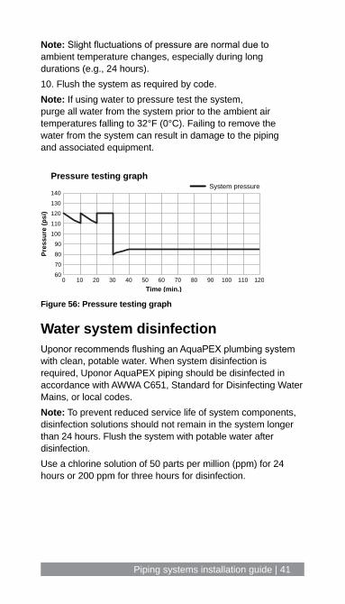
Note: Slight fluctuations of pressure are normal due to ambient temperature changes, especially during long durations (e.g., 24 hours).10. Flush the system as required by code.Note: If using water to pressure test the system, purge all water from the system prior to the ambient air temperatures falling to 32°F (0°C). Failing to remove the water from the system can result in damage to the piping and associated equipment.
Water system disinfectionUponor recommends flushing an AquaPEX plumbing system with clean, potable water. When system disinfection is required, Uponor AquaPEX piping should be disinfected in accordance with AWWA C651, Standard for Disinfecting Water Mains, or local codes.Note: To prevent reduced service life of system components, disinfection solutions should not remain in the system longer than 24 hours. Flush the system with potable water after disinfection.Use a chlorine solution of 50 parts per million (ppm) for 24 hours or 200 ppm for three hours for disinfection.
60
70
80
90
100
110
120
130
140
0 10 20 30 40 50 60 70 80 90 100 110 120
Pres
sure
(psi
)
Time (min.)
Pressure testing graph System pressure
Figure 56: Pressure testing graph

42 | uponorpro.com
Appendix A: Dimensions and physical characteristics of Uponor PEX pipeTable A-1: Dimensions and physical characteristics of SDR9 Uponor PEX pipe
Dim
ensi
ons
and
phys
ical
cha
ract
eris
tics
of S
DR9
Upon
or P
EX p
ipe
Nom
inal
pi
pe s
ize
Pipe
O.D
. (in
)Pi
pe I.
D. (i
n)W
eigh
t of p
ipe
on
ly lb
s/ft
(kg/
m)
Cont
ents
of p
ipe
gal/f
t (l/m
)W
eigh
t of p
ipe
and
wat
er lb
s/ft
(kg/
m)
¼"
0.37
50.
241
0.04
(0.0
18)
0.00
24 (0
.009
)0.
06 (0
.027
)
⅜"
0.50
0.35
0.05
(0.0
22)
0.00
5 (0
.018
)0.
09 (0
.040
)
½"
0.62
50.
475
0.06
(0.0
27)
0.00
92 (0
.034
)0.
14 (0
.063
)
⅝"
0.75
00.
574
0.08
(0.0
36)
0.01
34 (0
.050
)0.
19 (0
.086
)
¾"
0.87
50.
671
0.1
(0.0
45)
0.01
84 (0
.069
)0.
25 (0
.113
)
1"1.
125
0.86
20.
2 (0
.090
)0.
0303
(0.1
14)
0.45
(0.2
04)
1¼"
1.37
51.
054
0.34
(0.1
54)
0.04
53 (0
.171
)0.
72 (0
.326
)
1½"
1.62
51.
244
0.44
(0.1
99)
0.06
32 (0
.239
)0.
96 (0
.435
)
2"2.
125
1.62
90.
682
(0.3
09)
0.10
83 (0
.409
)1.
58 (0
.716
)
2½"
2.62
52.
011
0.93
(0.4
21)
0.16
49 (0
.624
)2.
3 (1
.043
)
3"3.
125
2.4
1.28
(0.5
80)
0.23
51 (0
.889
)3.
24 (1
.469
)

Piping systems installation guide | 43
Appendix B: Hydrostatic temperature and pressure ratingsUponor maintains standard-grade ratings for Uponor PEX piping. Uponor PEX carries the following temperature and pressure ratings shown in Table B-1. Note: Uponor EP and LF brass fittings carry the same temperature and pressure ratings as Uponor PEX pipe.
Table B-1: Hydrostatic temperature and pressure ratings for Uponor PEX pipe
ASTM F876 temperature and pressure ratings for SDR9 PEX
Rated temperature
Hydrostatic design stress (HDS) psi
Pressure rating for water psi
73.4°F/23°C 630 160 psi (11 bar)
180°F/82°C 400 100 psi (6.9 bar)
200°F/93°C 315 80 psi (5.5 bar)
Interpolation method Pressure ratings at different temperatures are determined by using a linear relationship between the standard-grade ratings. See Table B-2 for interpolated temperature and pressure ratings.
Excessive temperature and pressure capability In accordance with ASTM F876 Standard Specification for Crosslinked Polyethylene (PEX) Piping, the excessive temperature and pressure capability of Uponor PEX is 210ºF at 150 psi (99ºC at 10 bar). This standard requires that Uponor PEX piping maintain its integrity for a period of 720 hours (30 days) at 210ºF (99ºC) at 150 psi (10 bar). If installed as directed, Uponor PEX will withstand these conditions. Note: Excessive temperature and pressure requirements are always subject to approval by local building codes (e.g., temperature and pressure-relief valves).

44 | uponorpro.com
Table B-2: Interpolated hydrostatic temperature and pressure ratings for Uponor PEX pipe
Interpolated hydrostatic temperature and pressure ratings
ºF/ºC PSI/bar
200.0/93.3 80/5.5
190.0/87.8 90/6.2
180.0/82.2 100/6.9
170.0/76.7 106/7.3
160.0/71.1 111/7.7
150.0/65.6 117/8.0
140.0/60.0 123/8.5
130.0/54.4 128/8.8
120.0/48.9 134/9.2
110.0/43.3 139/9.6
100.0/37.8 145/10.0
90.0/32.2 151/10.4
80.0/26.7 156/10.8
73.4/23.0 160/11.0
60.0/15.6 168/11.6
50.0/10.0 173/11.9
40.0/4.4 179/12.3
Piping systems installation guide | 45
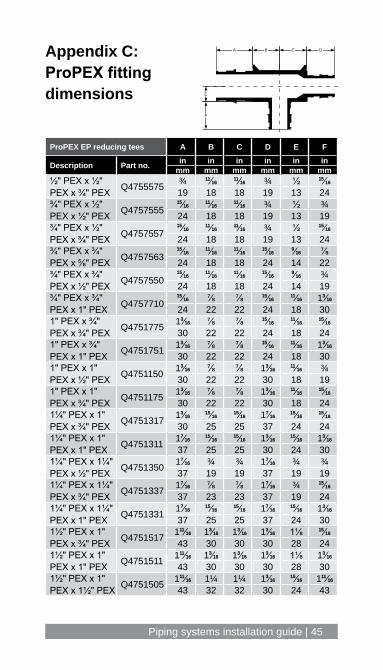
ProPEX EP reducing tees A B C D E F
Description Part no. in in in in in inmm mm mm mm mm mm
½" PEX x ½" PEX x ¾" PEX Q4755575 ¾ 1111⁄1616
1111⁄1616 ¾ ½ 1515⁄1616
19 18 18 19 13 24¾" PEX x ½" PEX x ½" PEX Q4757555
1515⁄16161111⁄1616
1111⁄1616 ¾ ½ ¾24 18 18 19 13 19
¾" PEX x ½" PEX x ¾" PEX Q4757557
1515⁄16161111⁄1616
1111⁄1616 ¾ ½ 1515⁄1616
24 18 18 19 13 24¾" PEX x ¾" PEX x ⅝" PEX Q4757563
1515⁄16161111⁄1616
1111⁄16161515⁄1616
99⁄1616 ⅞24 18 18 24 14 22
¾" PEX x ¾" PEX x ½" PEX Q4757550
1515⁄16161111⁄1616
1111⁄16161515⁄1616
99⁄1616 ¾24 18 18 24 14 19
¾" PEX x ¾" PEX x 1" PEX Q4757710
1515⁄1616 ⅞ ⅞ 1515⁄16161111⁄1616 133⁄1616
24 22 22 24 18 301" PEX x ¾" PEX x ¾" PEX Q4751775 133⁄1616 ⅞ ⅞ 1515⁄1616
1111⁄16161515⁄1616
30 22 22 24 18 241" PEX x ¾" PEX x 1" PEX Q4751751 133⁄1616 ⅞ ⅞ 1515⁄1616
1111⁄1616 133⁄1616
30 22 22 24 18 301" PEX x 1" PEX x ½" PEX Q4751150 133⁄1616 ⅞ ⅞ 133⁄1616
1111⁄1616 ¾30 22 22 30 18 19
1" PEX x 1" PEX x ¾" PEX Q4751175 133⁄1616 ⅞ ⅞ 133⁄1616
1111⁄16161515⁄1616
30 22 22 30 18 241¼" PEX x 1" PEX x ¾" PEX Q4751317 133⁄1616
1515⁄16161515⁄1616 177⁄1616
1515⁄16161515⁄1616
30 25 25 37 24 241¼" PEX x 1" PEX x 1" PEX Q4751311 177⁄1616
1515⁄16161515⁄1616 133⁄1616
1515⁄1616 133⁄1616
37 25 25 30 24 301¼" PEX x 1¼" PEX x ½" PEX Q4751350 177⁄1616 ¾ ¾ 177⁄1616 ¾ ¾
37 19 19 37 19 191¼" PEX x 1¼" PEX x ¾" PEX Q4751337 177⁄1616 ⅞ ⅞ 177⁄1616 ¾ 1515⁄1616
37 23 23 37 19 241¼" PEX x 1¼" PEX x 1" PEX Q4751331 177⁄1616
1515⁄16161515⁄1616 177⁄1616
1515⁄1616 133⁄1616
37 25 25 37 24 301½" PEX x 1" PEX x ¾" PEX Q4751517 11111⁄1616 133⁄1616 133⁄1616 133⁄1616 1⅛ 1515⁄1616
43 30 30 30 28 241½" PEX x 1" PEX x 1" PEX Q4751511 11111⁄1616 133⁄1616 133⁄1616 133⁄1616 1⅛ 133⁄1616
43 30 30 30 28 301½" PEX x 1" PEX x 1½" PEX Q4751505 11111⁄1616 1¼ 1¼ 133⁄1616
1515⁄1616 11111⁄1616
43 32 32 30 24 43
E
CA B D
F
Appendix C: ProPEX fitting dimensions
46 | uponorpro.com
E
CA B D
F
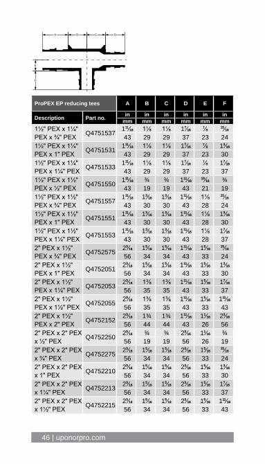
ProPEX EP reducing tees A B C D E F
Description Part no. in in in in in inmm mm mm mm mm mm
1½" PEX x 1¼" PEX x ¾" PEX Q4751537 11111⁄1616 1⅛ 1⅛ 177⁄1616 ⅞ 1515⁄1616
43 29 29 37 23 241½" PEX x 1¼" PEX x 1" PEX Q4751531 11111⁄1616 1⅛ 1⅛ 177⁄1616 ⅞ 133⁄1616
43 29 29 37 23 301½" PEX x 1¼" PEX x 1¼" PEX Q4751533 11111⁄1616 1⅛ 1⅛ 177⁄1616 ⅞ 177⁄1616
43 29 29 37 23 371½" PEX x 1½" PEX x ½" PEX Q4751550 11111⁄1616 ¾ ¾ 11111⁄1616
1313⁄1616 ¾43 19 19 43 21 19
1½" PEX x 1½" PEX x ¾" PEX Q4751557 11111⁄1616 133⁄1616 133⁄1616 11111⁄1616 1⅛ 1515⁄1616
43 30 30 43 28 241½" PEX x 1½" PEX x 1" PEX Q4751551 11111⁄1616 133⁄1616 133⁄1616 11111⁄1616 1⅛ 133⁄1616
43 30 30 43 28 301½" PEX x 1½" PEX x 1¼" PEX Q4751553 11111⁄1616 133⁄1616 133⁄1616 11111⁄1616 1⅛ 177⁄1616
43 30 30 43 28 372" PEX x 1½" PEX x ¾" PEX Q4752575 233⁄1616 155⁄1616 155⁄1616 11111⁄1616 155⁄1616
1515⁄1616
56 34 34 43 33 242" PEX x 1½" PEX x 1" PEX Q4752051 233⁄1616 155⁄1616 155⁄1616 11111⁄1616 155⁄1616 133⁄1616
56 34 34 43 33 302" PEX x 1½" PEX x 1¼" PEX Q4752053 233⁄1616 1⅜ 1⅜ 11111⁄1616 155⁄1616 177⁄1616
56 35 35 43 33 372" PEX x 1½" PEX x 1½" PEX Q4752055 233⁄1616 1⅜ 1⅜ 11111⁄1616 155⁄1616 11111⁄1616
56 35 35 43 33 432" PEX x 1½" PEX x 2" PEX Q4752152 233⁄1616 1¾ 1¾ 11111⁄1616 111⁄1616 233⁄1616
56 44 44 43 26 562" PEX x 2" PEX x ½" PEX Q4752250 233⁄1616 ¾ ¾ 233⁄1616 111⁄1616 ¾
56 19 19 56 26 192" PEX x 2" PEX x ¾" PEX Q4752275 233⁄1616 155⁄1616 155⁄1616 233⁄1616 155⁄1616
1515⁄1616
56 34 34 56 33 242" PEX x 2" PEX x 1" PEX Q4752210 233⁄1616 155⁄1616 155⁄1616 233⁄1616 155⁄1616 133⁄1616
56 34 34 56 33 302" PEX x 2" PEX x 1¼" PEX Q4752213 233⁄1616 155⁄1616 155⁄1616 233⁄1616 155⁄1616 177⁄1616
56 34 34 56 33 372" PEX x 2" PEX x 1½" PEX Q4752215 233⁄1616 155⁄1616 155⁄1616 233⁄1616 155⁄1616 11111⁄1616
56 34 34 56 33 43
Piping systems installation guide | 47
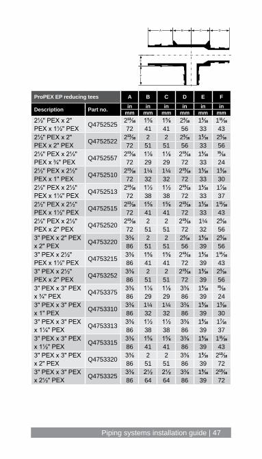
ProPEX EP reducing tees A B C D E F
Description Part no. in in in in in inmm mm mm mm mm mm
2½" PEX x 2" PEX x 1½" PEX Q4752525 21313⁄1616 1⅝ 1⅝ 233⁄1616 155⁄1616 11111⁄1616
72 41 41 56 33 432½" PEX x 2" PEX x 2" PEX Q4752522 21313⁄1616 2 2 233⁄1616 155⁄1616 233⁄1616
72 51 51 56 33 562½" PEX x 2½" PEX x ¾" PEX Q4752557 21313⁄1616 1⅛ 1⅛ 21313⁄1616 155⁄1616
1515⁄1616
72 29 29 72 33 242½" PEX x 2½" PEX x 1" PEX Q4752510 21313⁄1616 1¼ 1¼ 21313⁄1616 155⁄1616 133⁄1616
72 32 32 72 33 302½" PEX x 2½" PEX x 1¼" PEX Q4752513 21313⁄1616 1½ 1½ 21313⁄1616 155⁄1616 177⁄1616
72 38 38 72 33 372½" PEX x 2½" PEX x 1½" PEX Q4752515 21313⁄1616 1⅝ 1⅝ 21313⁄1616 155⁄1616 11111⁄1616
72 41 41 72 33 432½" PEX x 2½" PEX x 2" PEX Q4752520 21313⁄1616 2 2 21313⁄1616 1¼ 233⁄1616
72 51 51 72 32 563" PEX x 2" PEX x 2" PEX Q4753220 3⅜ 2 2 233⁄1616 199⁄1616 233⁄1616
86 51 51 56 39 563" PEX x 2½" PEX x 1½" PEX Q4753215 3⅜ 1⅝ 1⅝ 21313⁄1616 199⁄1616 11111⁄1616
86 41 41 72 39 433" PEX x 2½" PEX x 2" PEX Q4753252 3⅜ 2 2 21313⁄1616 199⁄1616 233⁄1616
86 51 51 72 39 563" PEX x 3" PEX x ¾" PEX Q4753375 3⅜ 1⅛ 1⅛ 3⅜ 199⁄1616
1515⁄1616
86 29 29 86 39 243" PEX x 3" PEX x 1" PEX Q4753310 3⅜ 1¼ 1¼ 3⅜ 199⁄1616 133⁄1616
86 32 32 86 39 303" PEX x 3" PEX x 1¼" PEX Q4753313 3⅜ 1½ 1½ 3⅜ 199⁄1616 177⁄1616
86 38 38 86 39 373" PEX x 3" PEX x 1½" PEX Q4753315 3⅜ 1⅝ 1⅝ 3⅜ 199⁄1616 11111⁄1616
86 41 41 86 39 433" PEX x 3" PEX x 2" PEX Q4753320 3⅜ 2 2 3⅜ 199⁄1616 21313⁄1616
86 51 51 86 39 723" PEX x 3" PEX x 2½" PEX Q4753325 3⅜ 2½ 2½ 3⅜ 199⁄1616 21313⁄1616
86 64 64 86 39 72
E
CA B D
F

48 | uponorpro.com
A
C
B
ProPEX tees A B C
Description Part no. in in inmm mm mm
½" PEX x ½" PEX x ½" PEX Q4755050 ¾ 99⁄1616 ⅜19 15 10
½" PEX x ½" PEX x ½" PEX LF47050501111⁄1616
99⁄161655⁄1616
18 14 8
¾" PEX x ¾" PEX x ¾" PEX Q47575751515⁄1616
1111⁄1616 ½24 18 13
¾" PEX x ¾" PEX x ¾" PEX LF47075751515⁄1616
1111⁄1616 ⅜24 18 10
1" PEX x 1" PEX x 1" PEX Q4751010 133⁄1616 ⅞ 1111⁄1616
30 22 18
1" PEX x 1" PEX x 1" PEX LF4701010 133⁄1616 ⅞ 99⁄1616
30 22 14
1¼" PEX x 1¼" PEX x 1¼" PEX Q4751313 177⁄16161515⁄1616
1515⁄1616
37 25 24
1½" PEX x 1½" PEX x 1½" PEX Q4751515 11111⁄1616 133⁄1616 1⅛43 30 28
2" PEX x 2" PEX x 2" PEX Q4752000 233⁄1616 199⁄1616 1⅝56 40 41
2½" PEX x 2½" PEX x 2½" PEX Q4752500 21313⁄1616 277⁄1616 155⁄1616
72 62 34
3" PEX x 3" PEX x 3" PEX Q4753000 3⅜ 2¾ 177⁄1616
86 70 37

Piping systems installation guide | 49
ProPEX elbows A B C D E
Description Part no. in in in in inmm mm mm mm mm
½" PEX x ½" PEX EP Elbow Q4760500
1111⁄1616 ¾ 99⁄1616 ¼21 19 14 7
¾" PEX x ¾" PEX EP Elbow Q4760750 111⁄1616
1515⁄16161111⁄1616 ⅜
27 24 17 10¾" PEX x ¾" PEX Brass Elbow LF4710750 111⁄1616
1515⁄16161111⁄1616 ⅜ ⅜
27 24 18 10 101" PEX x 1" PEX EP Elbow Q4761000 1⅝ 133⁄1616 ⅞ 1313⁄1616
42 30 22 201" PEX x 1" PEX Brass Elbow LF4711000 1¼ 133⁄1616 ⅞ 1313⁄1616
99⁄1616
32 30 22 14 141¼" PEX x 1¼" PEX EP Elbow Q4761250 1¾ 177⁄1616 1⅛ ⅝
43 37 28 151½" PEX x 1½" PEX EP Elbow Q4761500 1⅞ 11111⁄1616 133⁄1616
1111⁄1616
47 43 30 171½" PEX x 1½" PEX45 Elbow Q4761515 255⁄1616 11111⁄1616 ⅝
59 43 152" PEX x 2" PEX EP Elbow Q4762000 299⁄1616 233⁄1616 1⅝ 1515⁄1616
65 56 41 242" PEX x 2" PEX 45 Elbow Q4762020 21515⁄1616 233⁄1616 ¾
74 56 192½" PEX x 2½" PEX EP Elbow Q4762500 355⁄1616 21313⁄1616 2⅛ 133⁄1616
84 72 53 312½" PEX x 2½" PEX45 Elbow Q4762525 31313⁄1616 21313⁄1616 1
97 72 253" PEX x 3" PEX EP Elbow Q4763000 31515⁄1616 3⅜ 2½ 177⁄1616
99 86 64 363" PEX x 3" PEX 45 Elbow Q4763030 4½ 3⅜ 1⅛
114 86 28
A
D
B
C CA
E
B
D
C
A B
EP elbow Brass elbow EP elbow

50 | uponorpro.com
C
B
A
AB
C
ProPEX couplings A B C
Description Part no. in in inmm mm mm
½" PEX x ½" PEXQ4775050 ¾ ⅛ ¾
19 3 19
LF45450501111⁄1616 ⅛ 1111⁄1616
18 3 18
¾" PEX x ¾" PEXQ4777575
1515⁄1616 ⅛ 1515⁄1616
24 3 24
LF45475751515⁄1616 ⅛ 1515⁄1616
24 3 24
1" PEX x 1" PEXQ4771010 133⁄1616 ⅛ 133⁄1616
30 3 30
LF4541010 133⁄1616 ⅛ 133⁄1616
30 3 30
1¼" PEX x 1¼" PEX Q4771313 177⁄1616 ⅛ 177⁄1616
37 3 37
1½" PEX x 1½" PEX Q4771515 11111⁄1616 ⅛ 11111⁄1616
44 3 44
2" PEX x 2" PEX Q4772020 233⁄1616 ¼ 233⁄1616
56 6 56
2½" PEX x 2½" PEX Q4772525 21313⁄1616 ¼ 21313⁄1616
72 6 72
3" PEX x 3" PEX Q4773030 3⅜ ¼ 3⅜86 6 86

Piping systems installation guide | 51
ProPEX reducing couplings A B C
Description Part no. in in inmm mm mm
¾" PEX x ½" PEX Q4775075
1515⁄1616 ⅛ ¾24 3 19
1" PEX x ¾" PEX
Q4777510 133⁄1616 ⅛ 1515⁄1616
30 3 24
LF4547510 133⁄1616 ⅛ 1515⁄1616
30 3 241¼" PEX x ¾" PEX Q4771307 177⁄1616 ⅛ 1515⁄1616
37 3 241¼" PEX x 1" PEX Q4771310 177⁄1616 ⅛ 133⁄1616
37 3 301½" PEX x ¾" PEX Q4771507 11111⁄1616 ⅛ 1515⁄1616
44 3 241½" PEX x 1" PEX Q4771510 11111⁄1616 ⅛ 133⁄1616
44 3 301½" PEX x 1¼" PEX Q4771513 11111⁄1616 ⅛ 177⁄1616
44 3 372" PEX x 1½" PEX Q4772015 233⁄1616 ¼ 11111⁄1616
56 6 442½" PEX x 1¼" PEX Q4772513 21313⁄1616 ¼ 177⁄1616
72 6 372½" PEX x 1½" PEX Q4772515 21313⁄1616 ¼ 11111⁄1616
72 6 442½" PEX x 2" PEX Q4772520 21313⁄1616 ¼ 233⁄1616
72 6 56
3" PEX x 2" PEX Q4773020 3⅜ ¼ 233⁄1616
86 6 563" PEX x 2½" PEX Q4773025 3⅜ ¼ 21313⁄1616
86 6 72
C
B
A
AB
C

52 | uponorpro.com
ProPEX brass male threaded adapters A B C
Description Part no. in in inmm mm mm
⅜" PEX x ½" NPT LF45238501⅝ 1 ⅞41 25 22
½" PEX x ½" NPTQ5525050
1⅝ ⅞ ⅞41 23 22
LF452505011111⁄1616
1515⁄1616 ⅞42 24 22
½" PEX x ¾" NPT LF452507511313⁄1616 111⁄1616 1⅛45 27 29
¾" PEX x ¾" NPTLF4527575
1⅞ 1 1⅛48 25 29
Q55275751⅞ ⅞ 1⅛47 23 29
¾" PEX x 1" NPTLF4527510
2¼ 1¼ 1⅜56 32 35
Q55275102 111⁄1616 1⅜51 27 35
1" PEX x ¾" NPTLF4521075
2¼ 111⁄1616 1¼57 27 32
Q5521075211⁄1616 111⁄1616 1¼53 27 32
1" PEX x 1" NPTLF4521010
255⁄1616 1⅛ 1⅜59 29 35
Q55210102¼ 111⁄1616 1⅜57 27 35
1¼" PEX x 1¼" NPTLF4521313
2⅝ 133⁄1616 1¾66 30 44
Q55213132½ 111⁄1616 1¾64 27 44
AB
C
Piping systems installation guide | 53
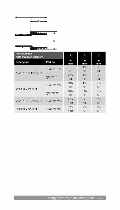
ProPEX brass male threaded adapters A B C
Description Part no. in in inmm mm mm
1½" PEX x 1½" NPTLF4521515
3 1¼ 276 32 51
Q552151521515⁄1616 1¼ 274 32 51
2" PEX x 2" NPTLF4522020
399⁄1616 1⅜ 2⅜90 35 60
Q5522020377⁄1616 155⁄1616 2⅜87 33 60
2½" PEX x 2½" NPT LF452252541313⁄1616 2 3¼123 51 83
3" PEX x 3" NPT LF45230305½ 2⅛ 3¾140 55 95
AB
C
54 | uponorpro.com
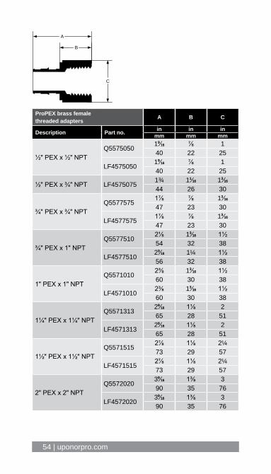
ProPEX brass female threaded adapters A B C
Description Part no. in in inmm mm mm
½" PEX x ½" NPTQ5575050
199⁄1616 ⅞ 140 22 25
LF4575050199⁄1616 ⅞ 140 22 25
½" PEX x ¾" NPT LF45750751¾ 111⁄1616 133⁄1616
44 26 30
¾" PEX x ¾" NPTQ5577575
1⅞ ⅞ 133⁄1616
47 23 30
LF45775751⅞ ⅞ 133⁄1616
47 23 30
¾" PEX x 1" NPTQ5577510
2⅛ 133⁄1616 1½54 32 38
LF4577510233⁄1616 1¼ 1½56 32 38
1" PEX x 1" NPTQ5571010
2⅜ 133⁄1616 1½60 30 38
LF45710102⅜ 133⁄1616 1½60 30 38
1¼" PEX x 1¼" NPTQ5571313
299⁄1616 1⅛ 265 28 51
LF4571313299⁄1616 1⅛ 265 28 51
1½" PEX x 1½" NPTQ5571515
2⅞ 1⅛ 2¼73 29 57
LF45715152⅞ 1⅛ 2¼73 29 57
2" PEX x 2" NPTQ5572020
399⁄1616 1⅜ 390 35 76
LF4572020399⁄1616 1⅜ 390 35 76
B
A
C

Piping systems installation guide | 55
BA
C
DE
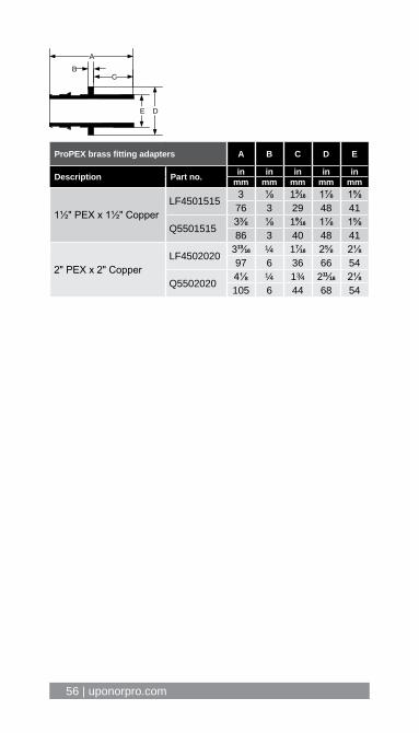
ProPEX brass fitting adapters A B C D E
Description Part no. in in in in inmm mm mm mm mm
½" PEX x ½" CopperLF4505050 1⅜ ⅛ 99⁄1616 ¾ ⅝
35 3 14 19 16
Q5505050 11111⁄1616 ⅛ ⅞ ¾ ⅝43 3 22 19 16
½" PEX x ¾" Copper LF4505075 1⅝ ⅛ 1313⁄16161515⁄1616 ⅞
42 3 21 23 22
⅝" PEX x ½" Copper Q4506350 199⁄1616 ⅛ 99⁄1616 111⁄1616 ⅝39 3 14 26 16
⅝" PEX x ¾" Copper Q4506375 11313⁄1616 ⅛ 1313⁄16161515⁄1616 ⅞
46 3 21 24 22
¾" PEX x ½" CopperLF4507550 1⅝ ⅛ 99⁄1616 1⅛ ⅝
41 3 14 28 16
Q5507550 11515⁄1616 ⅛ ⅞ 1⅛ ⅝50 3 22 28 16
¾" PEX x ¾" CopperLF4507575 1⅞ ⅛ 1313⁄1616 1⅛ ⅞
48 3 21 28 22
Q5507575 211⁄1616 ⅛ 1 1⅛ ⅞53 3 25 28 22
¾" PEX x 1" CopperLF4507510 211⁄1616 ⅛ 1 133⁄1616 1⅛
53 3 25 30 28
Q5507510 211⁄1616 ⅛ 1 1⅛ 1⅛53 3 25 29 28
1" PEX x 1" CopperLF4501010 2¼ ⅛ 1 1⅜ 1⅛
58 3 25 35 29
Q5501010 255⁄1616 ⅛ 1 1⅜ 1⅛59 3 25 35 29
1¼" PEX x 1¼" CopperLF4501313 2⅝ ⅛ 1 1⅝ 1⅜
66 3 25 42 35
Q5501313 21111⁄1616 ⅛ 1⅛ 1¾ 1⅜69 3 29 44 35
56 | uponorpro.com
BA
C
DE
ProPEX brass fitting adapters A B C D E
Description Part no. in in in in inmm mm mm mm mm
1½" PEX x 1½" CopperLF4501515 3 ⅛ 133⁄1616 1⅞ 1⅝
76 3 29 48 41
Q5501515 3⅜ ⅛ 199⁄1616 1⅞ 1⅝86 3 40 48 41
2" PEX x 2" CopperLF4502020 31313⁄1616 ¼ 177⁄1616 2⅝ 2⅛
97 6 36 66 54
Q5502020 4⅛ ¼ 1¾ 21111⁄1616 2⅛105 6 44 68 54
Piping systems installation guide | 57
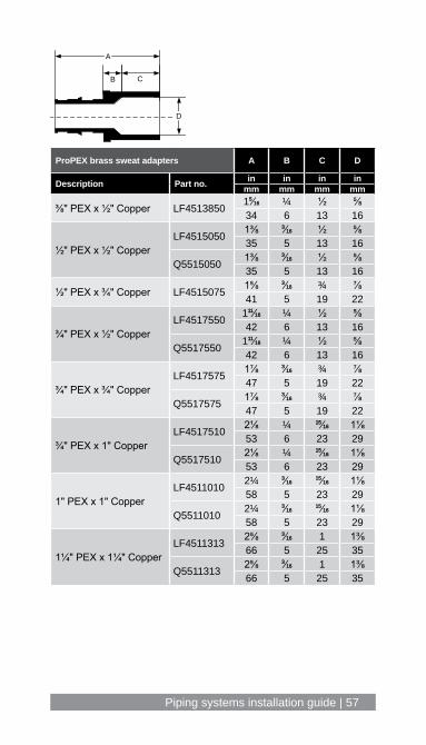
ProPEX brass sweat adapters A B C D
Description Part no. in in in inmm mm mm mm
⅜" PEX x ½" Copper LF4513850 155⁄1616 ¼ ½ ⅝34 6 13 16
½" PEX x ½" CopperLF4515050 1⅜ 33⁄1616 ½ ⅝
35 5 13 16
Q5515050 1⅜ 33⁄1616 ½ ⅝35 5 13 16
½" PEX x ¾" Copper LF4515075 1⅝ 33⁄1616 ¾ ⅞41 5 19 22
¾" PEX x ½" CopperLF4517550 11111⁄1616 ¼ ½ ⅝
42 6 13 16
Q5517550 11111⁄1616 ¼ ½ ⅝42 6 13 16
¾" PEX x ¾" CopperLF4517575 1⅞ 33⁄1616 ¾ ⅞
47 5 19 22
Q5517575 1⅞ 33⁄1616 ¾ ⅞47 5 19 22
¾" PEX x 1" CopperLF4517510 2⅛ ¼ 1515⁄1616 1⅛
53 6 23 29
Q5517510 2⅛ ¼ 1515⁄1616 1⅛53 6 23 29
1" PEX x 1" CopperLF4511010 2¼ 33⁄1616
1515⁄1616 1⅛58 5 23 29
Q5511010 2¼ 33⁄16161515⁄1616 1⅛
58 5 23 29
1¼" PEX x 1¼" CopperLF4511313 2⅝ 33⁄1616 1 1⅜
66 5 25 35
Q5511313 2⅝ 33⁄1616 1 1⅜66 5 25 35
B
A
C
D

58 | uponorpro.com
ProPEX brass sweat adapters A B C D
Description Part no. in in in inmm mm mm mm
1½" PEX x 1½" CopperLF4511515 333⁄1616 ¼ 111⁄1616 1⅝
78 6 28 41
Q5511515 333⁄1616 ¼ 111⁄1616 1⅝78 6 28 41
2" PEX x 2" CopperLF4512020 3¾ ¼ 155⁄1616 2⅛
95 6 34 54
Q5512020 3¾ ¼ 155⁄1616 2⅛95 6 34 54
2½" PEX x 2½" Copper LF4512525 499⁄161655⁄1616 177⁄1616 2⅝
116 8 37 67
3" PEX x 3" Copper LF4513030 555⁄161655⁄1616 11111⁄1616 3⅛
135 8 42 80
B
A
C
D
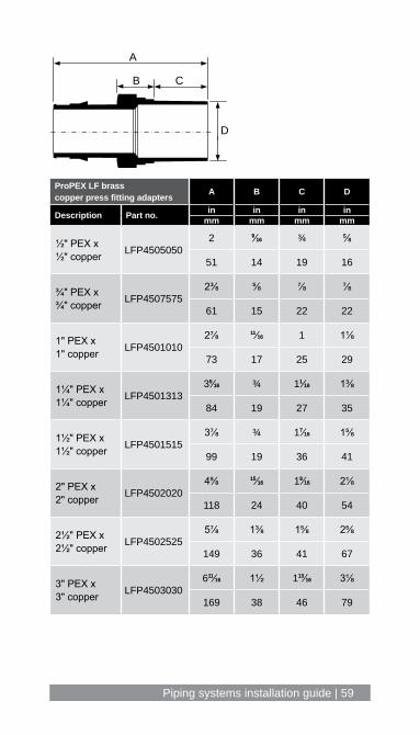
Piping systems installation guide | 59
ProPEX LF brass copper press fitting adapters A B C D
Description Part no. in in in inmm mm mm mm
½" PEX x ½" copper LFP4505050
2 99⁄1616 ¾ ⅝
51 14 19 16
¾" PEX x ¾" copper LFP4507575
2⅜ ⅝ ⅞ ⅞
61 15 22 22
1" PEX x 1" copper LFP4501010
2⅞ 1111⁄1616 1 1⅛
73 17 25 29
1¼" PEX x 1¼" copper LFP4501313
355⁄1616 ¾ 111⁄1616 1⅜
84 19 27 35
1½" PEX x 1½" copper LFP4501515
3⅞ ¾ 177⁄1616 1⅝
99 19 36 41
2" PEX x 2" copper LFP4502020
4⅝ 1515⁄1616 199⁄1616 2⅛
118 24 40 54
2½" PEX x 2½" copper LFP4502525
5⅞ 1⅜ 1⅝ 2⅝
149 36 41 67
3" PEX x 3" copper LFP4503030
61111⁄1616 1½ 11313⁄1616 3⅛
169 38 46 79
A
B C
D
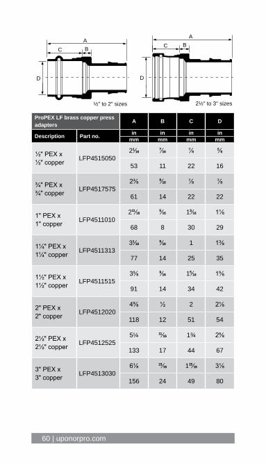
60 | uponorpro.com
ProPEX LF brass copper press adapters A B C D
Description Part no. in in in inmm mm mm mm
½" PEX x ½" copper LFP4515050
211⁄161677⁄1616 ⅞ ⅝
53 11 22 16
¾" PEX x ¾" copper LFP4517575
2⅜ 99⁄1616 ⅞ ⅞
61 14 22 22
1" PEX x 1" copper LFP4511010
21111⁄161655⁄1616 133⁄1616 1⅛
68 8 30 29
1¼" PEX x 1¼" copper LFP4511313
311⁄161699⁄1616 1 1⅜
77 14 25 35
1½" PEX x 1½" copper LFP4511515
3⅝ 99⁄1616 155⁄1616 1⅝
91 14 34 42
2" PEX x 2" copper LFP4512020
4⅝ ½ 2 2⅛
118 12 51 54
2½" PEX x 2½" copper LFP4512525
5¼ 1111⁄1616 1¾ 2⅝
133 17 44 67
3" PEX x 3" copper LFP4513030
6⅛ 1515⁄1616 11515⁄1616 3⅛
156 24 49 80
AC B
D
2½" to 3" sizes½" to 2" sizes
AC B
D
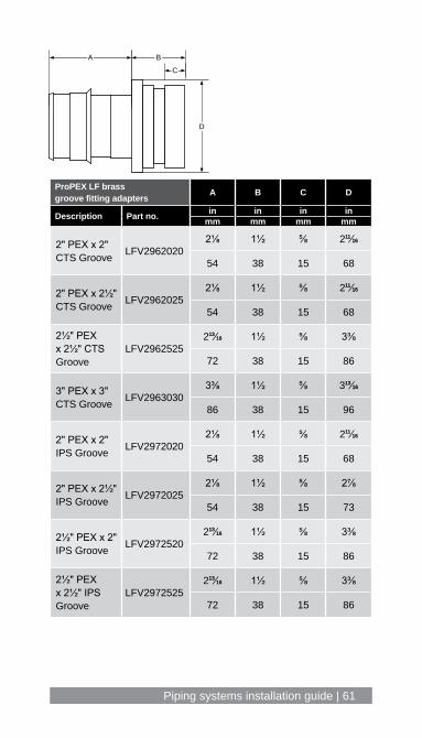
Piping systems installation guide | 61
ProPEX LF brass groove fitting adapters A B C D
Description Part no. in in in inmm mm mm mm
2" PEX x 2" CTS Groove LFV2962020
2⅛ 1½ ⅝ 21111⁄1616
54 38 15 68
2" PEX x 2½" CTS Groove LFV2962025
2⅛ 1½ ⅝ 21111⁄1616
54 38 15 68
2½" PEX x 2½" CTS Groove
LFV296252521313⁄1616 1½ ⅝ 3⅜
72 38 15 86
3" PEX x 3" CTS Groove LFV2963030
3⅜ 1½ ⅝ 31313⁄1616
86 38 15 96
2" PEX x 2" IPS Groove LFV2972020
2⅛ 1½ ⅝ 21111⁄1616
54 38 15 68
2" PEX x 2½" IPS Groove LFV2972025
2⅛ 1½ ⅝ 2⅞
54 38 15 73
2½" PEX x 2" IPS Groove LFV2972520
21313⁄1616 1½ ⅝ 3⅜
72 38 15 86
2½" PEX x 2½" IPS Groove
LFV297252521313⁄1616 1½ ⅝ 3⅜
72 38 15 86
B
C
D
A
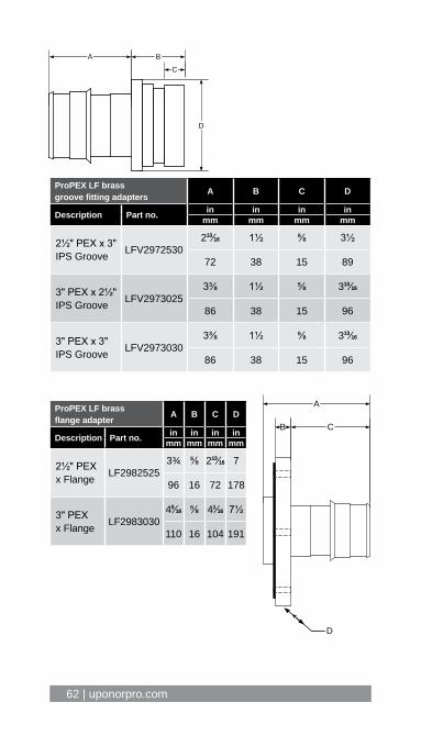
62 | uponorpro.com
ProPEX LF brass groove fitting adapters A B C D
Description Part no. in in in inmm mm mm mm
2½" PEX x 3" IPS Groove LFV2972530
21313⁄1616 1½ ⅝ 3½
72 38 15 89
3" PEX x 2½" IPS Groove LFV2973025
3⅜ 1½ ⅝ 31313⁄1616
86 38 15 96
3" PEX x 3" IPS Groove LFV2973030
3⅜ 1½ ⅝ 31313⁄1616
86 38 15 96
ProPEX LF brass flange adapter A B C D
Description Part no. in in in inmm mm mm mm
2½" PEX x Flange LF2982525
3¾ ⅝ 21313⁄1616 7
96 16 72 178
3" PEX x Flange LF2983030
455⁄1616 ⅝ 411⁄1616 7½
110 16 104 191
B
C
D
A
B C
D
A
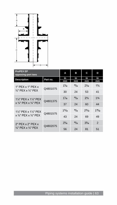
Piping systems installation guide | 63
ProPEX EP opposing-port tees A B C D
Description Part no. in in in inmm mm mm mm
1" PEX x 1" PEX x ¾" PEX x ¾" PEX Q4801075
133⁄16161515⁄1616 211⁄1616 1⅝
30 24 53 41
1¼" PEX x 1¼" PEX x ¾" PEX x ¾" PEX Q4801375
177⁄16161515⁄1616 2⅜ 1¾
37 24 60 44
1½" PEX x 1½" PEX x ¾" PEX x ¾" PEX Q4801575
11111⁄16161515⁄1616 21111⁄1616 11515⁄1616
43 24 69 49
2" PEX x 2" PEX x ¾" PEX x ¾" PEX Q4802075
233⁄16161515⁄1616 333⁄1616 2
56 24 81 51
B
A
C
D

64 | uponorpro.com
ProPEX brass ball valves A B C D E F G H
Description Part no. in in in in in in in inmm mm mm mm mm mm mm mm
½" PEX x ½" PEX
A3205050 2½ 1111⁄1616 111⁄1616 ⅜ ½ 11111⁄1616 3⅜ ⅜64 18 27 10 12 43 86 10
LFC4825050 2½ 1111⁄1616 111⁄1616 ⅜ ½ 11111⁄1616 3⅜ ⅜64 18 27 10 12 43 86 10
¾" PEX x ¾" PEX
A3207575 3⅜ 1515⁄1616 1½ ½ ½ 1⅞ 3⅜ ⅜86 24 38 12 12 47 86 10
LFC4827575 3⅜ 1515⁄1616 1½ ½ ½ 1⅞ 3⅜ ⅜86 24 38 12 12 47 86 10
1" PEX x 1" PEX
A3201010 433⁄1616 133⁄1616 11313⁄1616 ¾ 1313⁄1616 1⅞ 477⁄1616 ½106 30 46 19 20 48 114 12
LFC4821010 433⁄1616 133⁄1616 11313⁄1616 ¾ 1313⁄1616 1⅞ 477⁄1616 ½106 30 46 19 20 48 114 12
1¼" PEX x 1¼" PEX
A3201313 41313⁄1616 177⁄1616 11515⁄1616 ⅝ 1515⁄1616 2¼ 477⁄1616 ½122 37 49 17 24 58 114 12
LFC4821313 41313⁄1616 177⁄1616 11515⁄1616 ⅝ 1515⁄1616 2¼ 477⁄1616 ½122 37 49 17 24 58 114 12
1½" PEX x 1½" PEX
A3201515 51111⁄1616 11111⁄1616 2⅛ 1515⁄1616 1⅛ 21111⁄1616 599⁄161699⁄1616
145 43 58 23 28 69 142 14
LFC4821515 51111⁄1616 11111⁄1616 2⅛ 1515⁄1616 1⅛ 21111⁄1616 599⁄161699⁄1616
145 43 58 23 28 69 142 14
2" PEX x 2" PEX
A3202020 7⅛ 2⅛ 21313⁄1616 1⅛ 177⁄1616 3⅜ 599⁄161699⁄1616
181 55 72 28 37 86 142 14
LFC4822020 7⅛ 2⅛ 21313⁄1616 1⅛ 177⁄1616 3⅜ 599⁄161699⁄1616
181 55 72 28 37 86 142 14
D
AB C
E
G
F
H
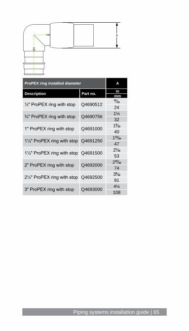
Piping systems installation guide | 65
ProPEX ring installed diameter A
Description Part no. inmm
½" ProPEX ring with stop Q46905121515⁄1616
24
¾" ProPEX ring with stop Q4690756 1¼32
1" ProPEX ring with stop Q4691000 199⁄1616
40
1¼" ProPEX ring with stop Q4691250 11313⁄1616
47
1½" ProPEX ring with stop Q4691500 211⁄1616
53
2" ProPEX ring with stop Q4692000 21515⁄1616
74
2½" ProPEX ring with stop Q4692500 399⁄1616
91
3" ProPEX ring with stop Q4693000 4¼108
A
66 | uponorpro.com
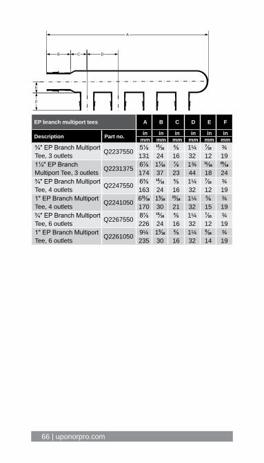
EP branch multiport tees A B C D E F
Description Part no. in in in in in inmm mm mm mm mm mm
¾" EP Branch Multiport Tee, 3 outlets Q2237550 5⅛ 1515⁄1616 ⅝ 1¼ 77⁄1616 ¾
131 24 16 32 12 191¼" EP Branch Multiport Tee, 3 outlets Q2231375 6⅞ 177⁄1616 ⅞ 1¾ 1111⁄1616
1515⁄1616
174 37 23 44 18 24¾" EP Branch Multiport Tee, 4 outlets Q2247550 6⅜ 1515⁄1616 ⅝ 1¼ 77⁄1616 ¾
163 24 16 32 12 191" EP Branch Multiport Tee, 4 outlets Q2241050 61111⁄1616 133⁄1616
1313⁄1616 1¼ ⅝ ¾170 30 21 32 15 19
¾" EP Branch Multiport Tee, 6 outlets Q2267550 8⅞ 1515⁄1616 ⅝ 1¼ 77⁄1616 ¾
226 24 16 32 12 191" EP Branch Multiport Tee, 6 outlets Q2261050 9¼ 133⁄1616 ⅝ 1¼ 99⁄1616 ¾
235 30 16 32 14 19
A
B C D
E
F
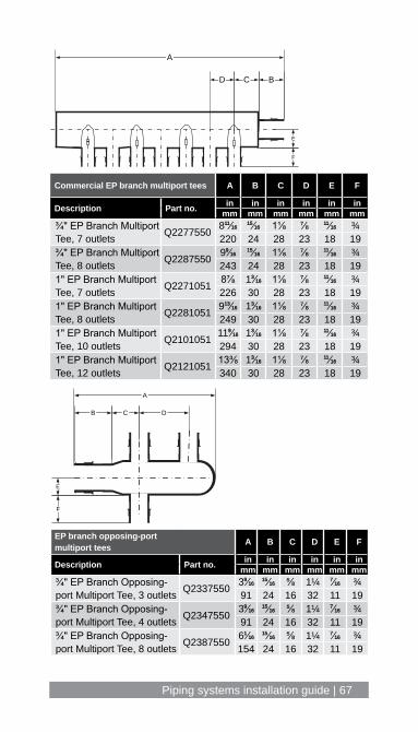
Piping systems installation guide | 67
EP branch opposing-port multiport tees A B C D E F
Description Part no. in in in in in inmm mm mm mm mm mm
¾" EP Branch Opposing-port Multiport Tee, 3 outlets Q2337550 399⁄1616
1515⁄1616 ⅝ 1¼ 77⁄1616 ¾91 24 16 32 11 19
¾" EP Branch Opposing-port Multiport Tee, 4 outlets Q2347550 399⁄1616
1515⁄1616 ⅝ 1¼ 77⁄1616 ¾91 24 16 32 11 19
¾" EP Branch Opposing-port Multiport Tee, 8 outlets Q2387550 611⁄1616
1515⁄1616 ⅝ 1¼ 77⁄1616 ¾154 24 16 32 11 19
A
D C B
E
F
A
B C D
E
F
Commercial EP branch multiport tees A B C D E F
Description Part no. in in in in in inmm mm mm mm mm mm
¾" EP Branch Multiport Tee, 7 outlets Q2277550 81111⁄1616
1515⁄1616 1⅛ ⅞ 1111⁄1616 ¾220 24 28 23 18 19
¾" EP Branch Multiport Tee, 8 outlets Q2287550 999⁄1616
1515⁄1616 1⅛ ⅞ 1111⁄1616 ¾243 24 28 23 18 19
1" EP Branch Multiport Tee, 7 outlets Q2271051 8⅞ 133⁄1616 1⅛ ⅞ 1111⁄1616 ¾
226 30 28 23 18 191" EP Branch Multiport Tee, 8 outlets Q2281051 91313⁄1616 133⁄1616 1⅛ ⅞ 1111⁄1616 ¾
249 30 28 23 18 191" EP Branch Multiport Tee, 10 outlets Q2101051 1199⁄1616 133⁄1616 1⅛ ⅞ 1111⁄1616 ¾
294 30 28 23 18 191" EP Branch Multiport Tee, 12 outlets Q2121051 13⅜ 133⁄1616 1⅛ ⅞ 1111⁄1616 ¾
340 30 28 23 18 19

68 | uponorpro.com
EP flow-through multiport tees A B C D E F G H
Description Part no. in in in in in in in inmm mm mm mm mm mm mm mm
2 outlets, ¾" x ¾" Q2227557
4⅜ 1515⁄1616 2½ 1515⁄1616 ⅝ 1¼ 77⁄1616 ¾
112 24 64 24 16 32 11 19
3 outlets, ¾" x ¾" Q2237557
51111⁄16161515⁄1616 3¾ 1515⁄1616 ⅝ 1¼ 77⁄1616 ¾
143 24 95 24 16 32 11 19
3 outlets, 1" x ¾" Q2231057
633⁄1616 133⁄1616 411⁄16161515⁄1616 ¾ 1¼ 99⁄1616 ¾
157 30 103 24 19 32 14 19
3 outlets, 1¾" x 1¼" Q2231373
833⁄1616 177⁄1616 555⁄1616 177⁄1616 ⅞ 1¾ ⅝ 1
208 37 135 37 23 44 17 25
3 outlets, 2" x 2" Q223210210⅝ 233⁄1616 6¼ 233⁄1616 1⅛ 2 1515⁄1616 155⁄1616
269 56 158 56 28 51 24 33
4 outlets, ¾" x ¾" Q2247557
71313⁄16161515⁄1616 5⅞ 1515⁄1616
1111⁄1616 1½ 77⁄1616 ¾
198 24 150 24 18 38 11 19
4 outlets, 1" x ¾" Q2241057
7⅛ 133⁄1616 5 1515⁄1616 ⅝ 1¼ 99⁄1616 ¾
180 30 127 24 16 32 14 19
4 outlets, 1" x 1" Q224105171111⁄1616 133⁄1616 555⁄1616 133⁄1616 ¾ 1¼ 99⁄1616 ¾
195 30 135 30 19 32 14 19
6 outlets, ¾" x ¾" Q2267557
9⅜ 1515⁄1616 7½ 1515⁄1616 ⅝ 1¼ 77⁄1616 ¾
239 24 191 24 16 32 11 19
6 outlets, 1" x ¾" Q2261057
9⅝ 133⁄1616 7½ 1515⁄1616 ⅝ 1¼ 99⁄1616 ¾
244 30 191 24 16 32 14 19
6 outlets, 1" x 1" Q22610519⅞ 133⁄1616 7½ 133⁄1616 ⅝ 1¼ 99⁄1616 ¾
251 30 191 30 16 32 14 19
A
B C D
E F
G
H
Piping systems installation guide | 69
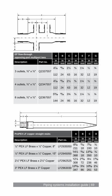
EP flow-through opposing-port multiport tees A B C D E F G
Description Part no. in in in in in in inmm mm mm mm mm mm mm
3 outlets, ¾" x ¾" Q2337557477⁄1616
1515⁄1616 2½ ⅝ 1¼ ½ ¾
112 24 63 16 32 12 19
4 outlets, ¾" x ¾" Q2347557477⁄1616
1515⁄1616 2½ ⅝ 1¼ ½ ¾
112 24 63 16 32 12 19
6 outlets, ¾" x ¾" Q236755751111⁄1616
1515⁄1616 3¾ ⅝ 1¼ ½ ¾
144 24 95 16 32 12 19
B
F
A
C
D E
G
A
D
B C
ProPEX LF copper straight stubs A B C D
Description Part no. in in in inmm mm mm mm
½" PEX LF Brass x ½" Copper, 8" LF2935050 855⁄16161111⁄1616 799⁄1616 ⅜
211 18 193 10
½" PEX LF Brass x ½" Copper, 15" LF2945050 14½ 1111⁄1616 131313⁄1616 ⅜368 18 350 10
2½" PEX LF Brass x 2½" Copper LF2962525 12⅛ 21313⁄1616 9¼ 11313⁄1616
308 72 236 46
3" PEX LF Brass x 3" Copper LF2963030 131111⁄1616 3⅜ 1055⁄1616 2⅛347 86 261 53
70 | uponorpro.com
A
B C
E
FD
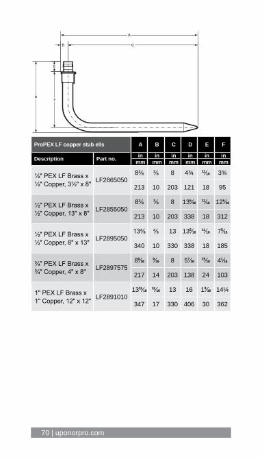
ProPEX LF copper stub ells A B C D E F
Description Part no. in in in in in inmm mm mm mm mm mm
½" PEX LF Brass x ½" Copper, 3½" x 8" LF2865050
8⅜ ⅜ 8 4¾ 1111⁄1616 3¾
213 10 203 121 18 95
½" PEX LF Brass x ½" Copper, 13" x 8" LF2855050
8⅜ ⅜ 8 1355⁄16161111⁄1616 1255⁄1616
213 10 203 338 18 312
½" PEX LF Brass x ½" Copper, 8" x 13" LF2895050
13⅜ ⅜ 13 1355⁄16161111⁄1616 755⁄1616
340 10 330 338 18 185
¾" PEX LF Brass x ¾" Copper, 4" x 8" LF2897575
899⁄161699⁄1616 8 577⁄1616
1515⁄1616 411⁄1616
217 14 203 138 24 103
1" PEX LF Brass x 1" Copper, 12" x 12" LF2891010
131111⁄16161111⁄1616 13 16 133⁄1616 14¼
347 17 330 406 30 362

Piping systems installation guide | 71
A
C
E
B
DF
ProPEX LF copper tub ells A B C D E F
Description Part no. in in in in in inmm mm mm mm mm mm
½" PEX LF Brass x ½" Copper, 3" x 6" LF2875050
3⅜ ⅜ 3 655⁄16161111⁄1616 5¼
86 10 76 160 18 134
½" PEX LF Brass x ½" Copper, 3" x 4" LF2885050
3⅜ ⅜ 3 455⁄16161111⁄1616 3¼
86 10 76 109 18 83
72 | uponorpro.com
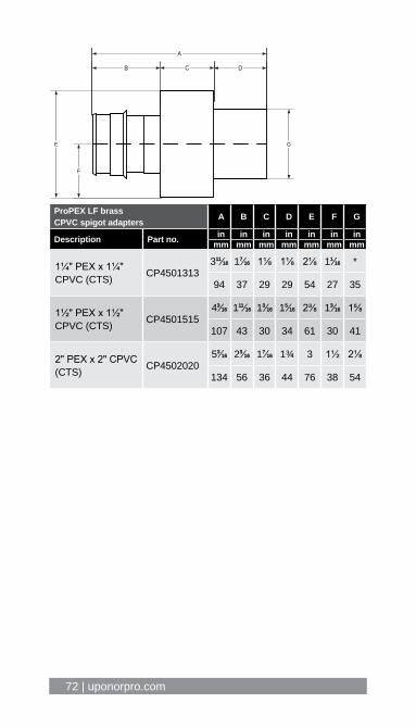
A
E
B C D
F
G
ProPEX LF brass CPVC spigot adapters A B C D E F G
Description Part no. in in in in in in inmm mm mm mm mm mm mm
1¼" PEX x 1¼" CPVC (CTS) CP4501313
31111⁄1616 177⁄1616 1⅛ 1⅛ 2⅛ 111⁄1616 *
94 37 29 29 54 27 35
1½" PEX x 1½" CPVC (CTS) CP4501515
433⁄1616 11111⁄1616 133⁄1616 155⁄1616 2⅜ 133⁄1616 1⅝
107 43 30 34 61 30 41
2" PEX x 2" CPVC (CTS) CP4502020
533⁄1616 233⁄1616 177⁄1616 1¾ 3 1½ 2⅛
134 56 36 44 76 38 54
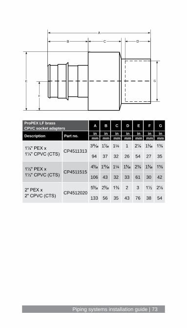
Piping systems installation guide | 73
ProPEX LF brass CPVC socket adapters A B C D E F G
Description Part no. in in in in in in inmm mm mm mm mm mm mm
1¼" PEX x 1¼" CPVC (CTS) CP4511313
31111⁄1616 177⁄1616 1¼ 1 2⅛ 111⁄1616 1⅜
94 37 32 26 54 27 35
1½" PEX x 1½" CPVC (CTS) CP4511515
433⁄1616 11111⁄1616 1¼ 155⁄1616 2⅜ 133⁄1616 1⅝
106 43 32 33 61 30 42
2" PEX x 2" CPVC (CTS) CP4512020
533⁄1616 233⁄1616 1⅜ 2 3 1½ 2⅛
133 56 35 43 76 38 54
A
E
B C D
F
G
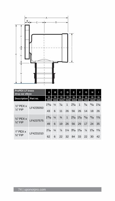
74 | uponorpro.com
ProPEX LF brass drop ear elbow A B C D E F G H I
Description Part no. in in in in in in in in inmm mm mm mm mm mm mm mm mm
½" PEX x ½" FIP LF4235050
11111⁄1616 ¼ 77⁄1616 1 233⁄1616 1 99⁄16161111⁄1616 111⁄1616
43 6 11 26 56 26 14 18 26
¾" PEX x ¾" FIP LF4237575
11515⁄1616 ¼ ¾ 1 233⁄1616 133⁄16161111⁄1616
1515⁄1616 1⅜
49 6 19 26 56 29 17 24 35
1" PEX x ¾" FIP LF4231010
277⁄1616 ¼ ⅞ 1¼ 355⁄1616 155⁄1616 ⅞ 133⁄1616 1⅝
62 6 22 32 84 33 22 30 42
AB
C D
E
F
G
H
I

Piping systems installation guide | 75
Appendix D: Uponor piping systems installation test questionsPlease circle the correct answer below.
Section 1 – General installations1. When making a ProPEX connection… a. Place the ProPEX ring on the pipe to the stop edge b. Make sure the head is installed and rotating properly c. Do not force the pipe onto the head when expanding d. Completely insert the fitting so the pipe/ring reach the
fitting shoulder e. All of the above
2. Maintain a minimum distance between ProPEX fittings... a. To prevent damage to fittings b. To prevent damage to expander heads c. All of the above
3. When storing Uponor PEX piping… a. Keep in its original packaging b. Keep out of direct UV light c. All of the above
4. When making ProPEX-to-copper transitions… a. Maintain a minimum of 18" between solder/sweat and
ProPEX connections b. Make solder/sweat connections prior to making
ProPEX connections c. Use ProPEX copper press adapters for a flameless transition d. All of the above
5. Uponor’s full 25-year warranty requires using Uponor PEX pipe with Uponor ProPEX rings and fittings.
a. True b. False
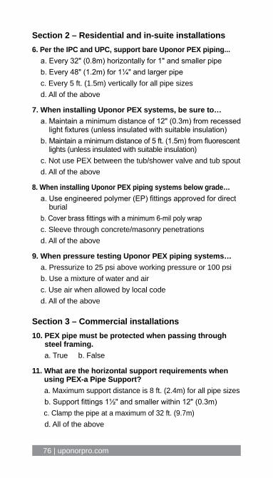
76 | uponorpro.com
Section 2 – Residential and in-suite installations6. Per the IPC and UPC, support bare Uponor PEX piping... a. Every 32" (0.8m) horizontally for 1" and smaller pipe b. Every 48" (1.2m) for 1¼" and larger pipe c. Every 5 ft. (1.5m) vertically for all pipe sizes d. All of the above
7. When installing Uponor PEX systems, be sure to… a. Maintain a minimum distance of 12" (0.3m) from recessed
light fixtures (unless insulated with suitable insulation) b. Maintain a minimum distance of 5 ft. (1.5m) from fluorescent
lights (unless insulated with suitable insulation) c. Not use PEX between the tub/shower valve and tub spout d. All of the above
8. When installing Uponor PEX piping systems below grade… a. Use engineered polymer (EP) fittings approved for direct
burial b. Cover brass fittings with a minimum 6-mil poly wrap c. Sleeve through concrete/masonry penetrations d. All of the above
9. When pressure testing Uponor PEX piping systems… a. Pressurize to 25 psi above working pressure or 100 psi b. Use a mixture of water and air c. Use air when allowed by local code d. All of the above
Section 3 – Commercial installations10. PEX pipe must be protected when passing through
steel framing. a. True b. False
11. What are the horizontal support requirements when using PEX-a Pipe Support?
a. Maximum support distance is 8 ft. (2.4m) for all pipe sizes b. Support fittings 1½" and smaller within 12" (0.3m) c. Clamp the pipe at a maximum of 32 ft. (9.7m) d. All of the above

Piping systems installation guide | 77
12. When installing PEX-a Pipe Support… a. Minimize cutting by using full lengths when possible b. Deburr sharp edges if cutting is required c. Strap according to Figures 35-38 in this guide d. All of the above
13. To minimize expansion and contraction in systems with ΔTs greater than 40°F (22.2°C)…
a. Support PEX with PEX-a Pipe Support and included straps
b. Clamp the pipe at a maximum 32 ft. (9.7m) on center c. Use fixed points according to length of run and pipe size d. All of the above
14. When installing Uponor PEX piping for vertical riser applications…
a. Support at the base of each floor with a CTS riser clamp b. Support every 5 ft. (1.5m) c. Clamp at the top of the floors according to system type
(e.g., domestic hot water, heating hot water, etc.) d. All of the above
15. When pressure testing large-volume commercial PEX systems…
a. Fill system with potable water, air or a combination of both
b. Condition the pipe to 1.5 times the test pressure or 120 psi (8.2 bar) for 30 minutes
c. After 30 minutes, release excess pressure until you reach desired test pressure [80 psi (5.5 bar) recommended]
d. Monitor system for leaks over the required time period e. All of the above

78 | uponorpro.com
Notes
____________________________________________
____________________________________________
____________________________________________
____________________________________________
____________________________________________
____________________________________________
____________________________________________
____________________________________________
____________________________________________
____________________________________________
____________________________________________
____________________________________________
____________________________________________
____________________________________________
____________________________________________
____________________________________________
____________________________________________
____________________________________________
____________________________________________
____________________________________________
____________________________________________
____________________________________________

Piping systems installation guide | 79
Notes
____________________________________________
____________________________________________
____________________________________________
____________________________________________
____________________________________________
____________________________________________
____________________________________________
____________________________________________
____________________________________________
____________________________________________
____________________________________________
____________________________________________
____________________________________________
____________________________________________
____________________________________________
____________________________________________
____________________________________________
____________________________________________
____________________________________________
____________________________________________
____________________________________________
____________________________________________

Uponor, Ltd. 6510 Kennedy Road Mississauga, ON L5T 2X4 CANADA
T 888.994.7726 F 800.638.9517
uponorpro.com
Uponor, Inc. 5925 148th Street West Apple Valley, MN 55124 USA
T 800.321.4739 F 952.891.2008
PipingSystemsInstallationGuide_03536_1119, Copyright © 2019 Uponor. Printed in the United States.