pilot tube guided boring in downtown minneapolis
TRANSCRIPT
12 MSTT - MIDWEST JOURNAL OF TRENCHLESS TECHNOLOGY 2016 WWW.MSTT.ORG
Project Goals
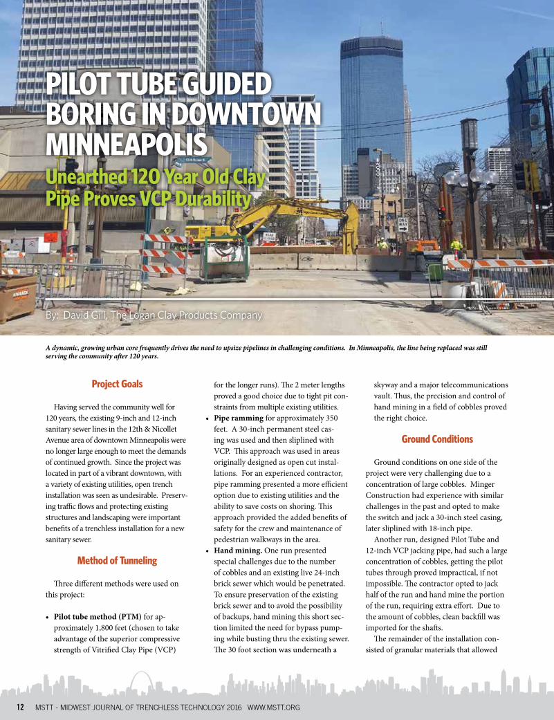
Having served the community well for 120 years, the existing 9-inch and 12-inch sanitary sewer lines in the 12th & Nicollet Avenue area of downtown Minneapolis were no longer large enough to meet the demands of continued growth. Since the project was located in part of a vibrant downtown, with a variety of existing utilities, open trench installation was seen as undesirable. Preserv-ing traffic flows and protecting existing structures and landscaping were important benefits of a trenchless installation for a new sanitary sewer.
Method of Tunneling
Three different methods were used on this project:
• Pilot tube method (PTM) for ap-proximately 1,800 feet (chosen to take advantage of the superior compressive strength of Vitrified Clay Pipe (VCP)
for the longer runs). The 2 meter lengths proved a good choice due to tight pit con-straints from multiple existing utilities.
• Pipe ramming for approximately 350 feet. A 30-inch permanent steel cas-ing was used and then sliplined with VCP. This approach was used in areas originally designed as open cut instal-lations. For an experienced contractor, pipe ramming presented a more efficient option due to existing utilities and the ability to save costs on shoring. This approach provided the added benefits of safety for the crew and maintenance of pedestrian walkways in the area.
• Hand mining. One run presented special challenges due to the number of cobbles and an existing live 24-inch brick sewer which would be penetrated. To ensure preservation of the existing brick sewer and to avoid the possibility of backups, hand mining this short sec-tion limited the need for bypass pump-ing while busting thru the existing sewer. The 30 foot section was underneath a
skyway and a major telecommunications vault. Thus, the precision and control of hand mining in a field of cobbles proved the right choice.
Ground Conditions
Ground conditions on one side of the project were very challenging due to a concentration of large cobbles. Minger Construction had experience with similar challenges in the past and opted to make the switch and jack a 30-inch steel casing, later sliplined with 18-inch pipe.
Another run, designed Pilot Tube and 12-inch VCP jacking pipe, had such a large concentration of cobbles, getting the pilot tubes through proved impractical, if not impossible. The contractor opted to jack half of the run and hand mine the portion of the run, requiring extra effort. Due to the amount of cobbles, clean backfill was imported for the shafts.
The remainder of the installation con-sisted of granular materials that allowed
By: David Gill, The Logan Clay Products Company
PILOT TUBE GUIDED BORING IN DOWNTOWN MINNEAPOLISUnearthed 120 Year Old Clay Pipe Proves VCP Durability
A dynamic, growing urban core frequently drives the need to upsize pipelines in challenging conditions. In Minneapolis, the line being replaced was still serving the community after 120 years.
MSTT - MIDWEST JOURNAL OF TRENCHLESS TECHNOLOGY 2016 WWW.MSTT.ORG 13
the project to proceed using a pilot tube installation as originally designed. This was the preferred method for more than 80% of this project.
Shafts
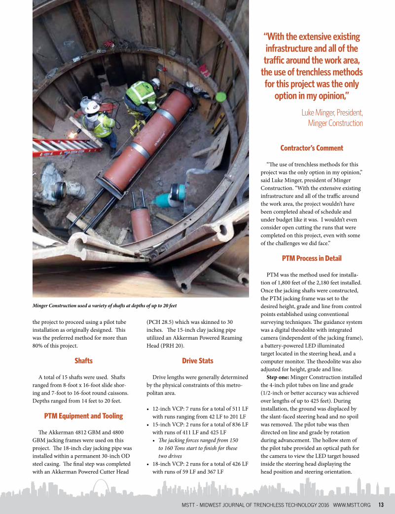
A total of 15 shafts were used. Shafts ranged from 8-foot x 16-foot slide shor-ing and 7-foot to 16-foot round caissons. Depths ranged from 14 feet to 20 feet.
PTM Equipment and Tooling
The Akkerman 4812 GBM and 4800 GBM jacking frames were used on this project. The 18-inch clay jacking pipe was installed within a permanent 30-inch OD steel casing. The final step was completed with an Akkerman Powered Cutter Head
(PCH 28.5) which was skinned to 30 inches. The 15-inch clay jacking pipe utilized an Akkerman Powered Reaming Head (PRH 20).
Drive Stats
Drive lengths were generally determined by the physical constraints of this metro-politan area.
• 12-inch VCP: 7 runs for a total of 511 LF with runs ranging from 42 LF to 201 LF
• 15-inch VCP: 2 runs for a total of 836 LF with runs of 411 LF and 425 LF• The jacking forces ranged from 150
to 160 Tons start to finish for these two drives
• 18-inch VCP: 2 runs for a total of 426 LF with runs of 59 LF and 367 LF
Contractor’s Comment
“The use of trenchless methods for this project was the only option in my opinion,” said Luke Minger, president of Minger Construction. “With the extensive existing infrastructure and all of the traffic around the work area, the project wouldn’t have been completed ahead of schedule and under budget like it was. I wouldn’t even consider open cutting the runs that were completed on this project, even with some of the challenges we did face.”
PTM Process in Detail
PTM was the method used for installa-tion of 1,800 feet of the 2,180 feet installed. Once the jacking shafts were constructed, the PTM jacking frame was set to the desired height, grade and line from control points established using conventional surveying techniques. The guidance system was a digital theodolite with integrated camera (independent of the jacking frame), a battery-powered LED illuminated target located in the steering head, and a computer monitor. The theodolite was also adjusted for height, grade and line.
Step one: Minger Construction installed the 4-inch pilot tubes on line and grade (1/2-inch or better accuracy was achieved over lengths of up to 425 feet). During installation, the ground was displaced by the slant-faced steering head and no spoil was removed. The pilot tube was then directed on line and grade by rotation during advancement. The hollow stem of the pilot tube provided an optical path for the camera to view the LED target housed inside the steering head displaying the head position and steering orientation.
Minger Construction used a variety of shafts at depths of up to 20 feet
“With the extensive existing infrastructure and all of the traffic around the work area,
the use of trenchless methods for this project was the only
option in my opinion,”
Luke Minger, President, Minger Construction
14 MSTT - MIDWEST JOURNAL OF TRENCHLESS TECHNOLOGY 2016 WWW.MSTT.ORG
This step established the center line of the new sewer installation; the remaining steps followed the path of the pilot tube. Once the pilot tubes reached the reception shaft, the theodolite, video camera, and monitor guidance system were no longer needed and were removed from the jacking pit.
Step two: the path of the pilot tube was followed with a 16-inch OD reaming head - the front of the reaming head fastened to the last pilot tube in the same manner in which the pilot tubes fasten to each other. Advancing the pilot tubes and reaming head were 16-inch OD thrust (auger) casings, which transported the spoil to the jacking shaft for removal. The contractor removed the spoil conventionally using a muck bucket. A vacuum could have been used as an alternative method of spoil removal.
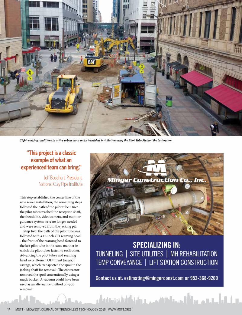
Tight working conditions in active urban areas make trenchless installation using the Pilot Tube Method the best option.
“This project is a classic example of what an
experienced team can bring,”
Jeff Boschert, President, National Clay Pipe Institute
Contact us at: [email protected] or 952-368-9200
SPECIALIZING IN:TUNNELING | SITE UTILITIES | MH REHABILITATION TEMP CONVEYANCE | LIFT STATION CONSTRUCTION
MSTT - MIDWEST JOURNAL OF TRENCHLESS TECHNOLOGY 2016 WWW.MSTT.ORG 15
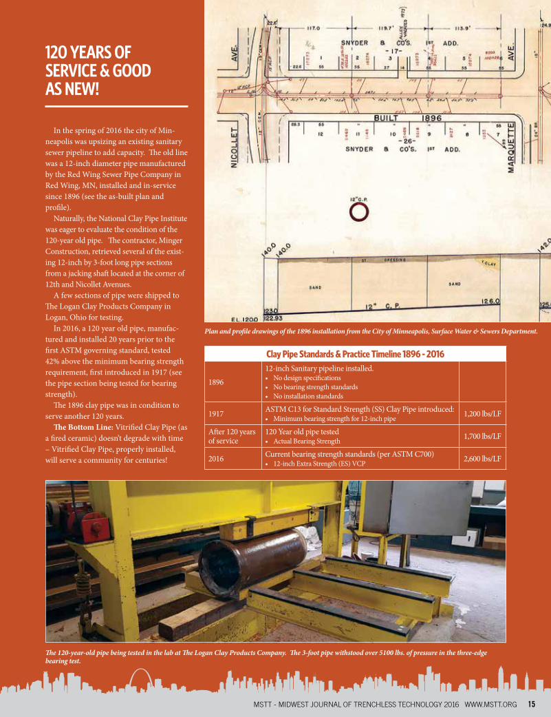
In the spring of 2016 the city of Min-neapolis was upsizing an existing sanitary sewer pipeline to add capacity. The old line was a 12-inch diameter pipe manufactured by the Red Wing Sewer Pipe Company in Red Wing, MN, installed and in-service since 1896 (see the as-built plan and profile).
Naturally, the National Clay Pipe Institute was eager to evaluate the condition of the 120-year old pipe. The contractor, Minger Construction, retrieved several of the exist-ing 12-inch by 3-foot long pipe sections from a jacking shaft located at the corner of 12th and Nicollet Avenues.
A few sections of pipe were shipped to The Logan Clay Products Company in Logan, Ohio for testing.
In 2016, a 120 year old pipe, manufac-tured and installed 20 years prior to the first ASTM governing standard, tested 42% above the minimum bearing strength requirement, first introduced in 1917 (see the pipe section being tested for bearing strength).
The 1896 clay pipe was in condition to serve another 120 years.
The Bottom Line: Vitrified Clay Pipe (as a fired ceramic) doesn’t degrade with time – Vitrified Clay Pipe, properly installed, will serve a community for centuries!
120 YEARS OF SERVICE & GOOD AS NEW!
Clay Pipe Standards & Practice Timeline 1896 - 2016
1896
12-inch Sanitary pipeline installed. • No design specifications• No bearing strength standards• No installation standards
1917 ASTM C13 for Standard Strength (SS) Clay Pipe introduced:• Minimum bearing strength for 12-inch pipe 1,200 lbs/LF
After 120 years of service
120 Year old pipe tested• Actual Bearing Strength 1,700 lbs/LF
2016 Current bearing strength standards (per ASTM C700)• 12-inch Extra Strength (ES) VCP 2,600 lbs/LF
The 120-year-old pipe being tested in the lab at The Logan Clay Products Company. The 3-foot pipe withstood over 5100 lbs. of pressure in the three-edge bearing test.
Plan and profile drawings of the 1896 installation from the City of Minneapolis, Surface Water & Sewers Department.
16 MSTT - MIDWEST JOURNAL OF TRENCHLESS TECHNOLOGY 2016 WWW.MSTT.ORG
During the installation of the casings in the jacking shaft, the previously installed pilot tubes were advanced into the recep-tion shaft and were disassembled. Step 2 was complete when the reamer and auger casings reached the reception shaft and all spoil was removed from the bore.
Final Step (12-inch ID VCP jacking pipe): Product pipe (16-inch OD) was installed directly behind the 16-inch thrust casings. The product pipes advanced the thrust casings into the reception shaft, where they were uncoupled and removed one-by-one. No spoil was removed in this step since the product pipe had the same outside diameter as the auger casings.
Final Step (15-inch ID VCP jacking pipe): The contractor installed a 20-inch OD Powered Reaming Head (PRH) behind the thrust casings which were advanced by the product pipe. The PRH increased the 16-inch bore to match the 20-inch OD of the product pipe. The remaining soil around the previously installed 16-inch OD thrust casings (step 2) was taken into the PRH and discharged via the reception shaft by reversing the auger flight direction. The final product pipe was then installed
directly behind the PRH in the jacking shaft. As each section of auger casing was removed from the reception shaft, a section of product pipe was installed in the jacking shaft until the process was completed. Step 2 was complete when the PRH entered the reception shaft advanced by the final product pipe.
Final Step (18-inch ID VCP jacking pipe): The process was the same as for 15-inch except the 18-inch product pipe was sliplined inside a 30-inch steel casing installed with a powered cutter head (PCH) due to ground conditions.
Housed inside the cutter face are three jetting ports connected by a single hose for water distribution to keep the face clean and ease spoil transport. Lubrication ports to keep jacking pressures down were located in the rear of the machine connected by a single hose. Seven hoses (four hydraulic, one lubrication, one jetting, and one for a hydraulic pump check valve) ran from the jacking frame though the product pipe to the PCH unit. Staging the VCP product pipe at the surface with the hoses installed before the start of this step was crucial to produc-tion timelines.
The Result:
“This project is a classic example of what an experienced team can bring to any project,” said Jeff Boschert, President of the National Clay Pipe Institute. “The trenchless expertise Minger brought to this project resulted a well-executed installation. The end result was a quickly ex-ecuted installation which will serve downtown Minneapolis for the next couple hundred years (or until they outgrow the line again).”
ABOUT THE AUTHOR:David Gill is Sales Engineer with The Logan Clay Products and has more than 25-years of experience in the sanitary sewer pipe industry. He has been
involved with countless open cut, pilot tube and pipe bursting projects in the United States and Canada. David speaks annually at the Colorado Tunneling Short Course on Vitrified Clay Jacking Pipe and presents educational information to municipalities and consulting firms on the technology of the Pilot Tube Method and Pipe Bursting. He holds a Bachelor of Science degree in construction engineering from the University of Nebraska Omaha.
Since inception, Akkerman has grown with the evolution of our industry demands. We offer pipe jacking, microtunneling, guided boring and earth pressure balance systems to address each project’s pipe specifications, ground conditions and complexities. Contact a sales engineer to pair the best option with your requirements.
akkerman.com | +1 (800) 533.0386
PIPE JACKING &TUNNELING
SOLUTIONS
DRIVEN FOR CUSTOMER SUCCESS
{ ESTABLISHED IN 1973 }
CHECK OUT OUR
NEW INVENTORY
WEBSITE
MILLIONS OF FEET INSPECTED• Screen 2+ miles per day• Low cost: 5¢ to 15¢ per foot• Simple integration with GIS• Highly portable and easy to operate
[email protected] • www.infosenseinc.com
OUR TECHNOLOGY IS BASED ON SOUND SCIENCEActive Acoustics screen for blockage with no flow contact
Inspect More, Clean Better