pile load test results as a basis for reliability
TRANSCRIPT
558 Technical Gazette 25, 2(2018), 558-564
ISSN 1330-3651 (Print), ISSN 1848-6339 (Online) https://doi.irg/10.17559/TV-20150124002223 Preliminary communication
Pile Load Test Results as a Basis for Reliability Calculation with Parabolic Response Surface
Jerzy BAUER, Wojciech PUŁA, Marek WYJADŁOWSKI
Abstract: The paper will discuss a method of analysing head displacements of piles subjected to lateral load test that is suitable for reliability calculation. The obtained results will be used for writing down the serviceability limit state equation related to a pile representing the group of piles under investigation. The obtained set of displacements for the test piles will be a base for creating a response surface function which may be used for determining reliability index of a pile foundation by means of FORM, SORM or Monte Carlo methods proposed by structural reliability theory. A classic response surface has a form of a polynomial of degree two. Unfortunately, this type of response surface produces erroneous reliability indices. The discussed method of allowable pile load estimation, based on load test results and using a parabolic response surface without an independent term for structural reliability theory calculations, is characterized by the easiness of obtaining a response surface. It is very easy to obtain results for this type of response surfaces by using FORM and SORM methods. Keywords: pile testing; reliability of structure; serviceability limit states 1 INTRODUCTION
The aim of the paper is to present a method of analysing indirect foundation load test results used for the purposes of foundation design employing probabilistic calculations. In compliance with Eurocode 7 [1] recommendations, pile foundation design is based on static load test results, and additionally also on other empirical and analytical methods.
Methods of calculating the bearing capacity of piles, using load-deformation curve analysis received during a load test have been described by many authors, including De Beer [2], Brinch-Hansen [3], Mazurkiewicz [4], Chin [5], Kondner [6], Decourt [7], Fellenius [8] and Meyer [9]. Unfortunately, these methods are employed chiefly in order to define the bearing capacity of vertically loaded piles.
Lateral load testing and result analysis can be also performed according to ASTM standards [10].
The work will propose an algorithm for defining the values of allowable lateral forces capable of displacing piles. Methods FORM and SORM of reliability of structure theory are going to be used for probabilistic calculation with test load results playing the role of response surface. The method will employ a response surface in the form of a parabolic function. Load test results will be used for calculating the value of a lateral force that will produce pile head displacement not exceeding a predetermined value with a defined probability (safety level). These forces will be further referred to as allowable at a defined safety level. The proposed method is particularly useful with large variations (random fluctuations) of soil parameters.
The methodology of analysing load test results will be presented on real measurements of pile head lateral displacements caused by a statically applied horizontal force. In order to reduce some calculations to simple arithmetical operations, an analysis of load test results for two piles will only be provided. A statistical analysis of these results by means of nonlinear regression method furnishes a parabolic response surface and then the magnitudes of allowable forces will be defined, taking
into consideration the values of reliability indices recommended by the ISO standard [11]. 2 LATERAL PILE LOAD TESTS
Lateral load tests were performed on 8.0 m long CFA piles with diameter ∅ of 500 mm. The maximum lateral load value, determined during the load test of the first pile, was 187 kN. In accordance with the Polish Norm [12] recommendation, it was divided into eleven 17 kN increments.
An deep foundation on piles was chosen because of unfavourable soil conditions. The soil was found to be composed of the following layers:
layer I - represented by fills built of slag, stones, sand, silt and clay with admixtures of wood, coal slurry, bricks, lime and petroleum derivatives. The part above the ground level consists of layers of aggregate, stones and asphalt. The total thickness of the fills is 5.6÷7.2 m. The designer classified the fills as a non-load bearing layer. − layer IIa – built of moderately compact medium sands locally contaminated with petroleum derivatives. These soils were found at the depth of 5.6÷7.2 m. The mean density index adopted for this layer is ID ≈ 0.50. − layer IIb1 – made of stiff clays, silty clays and cohesive silty clays close to silty clays. These soils were found below the depth of 6.6÷7.2 m. − layer IIb2 – composed of stiff silty clays lying below the depth of 11.1 m. The mean liquidity index adopted for this layer was IL ≈ 0.04.
The first layer is highly heterogeneous. It proved difficult to determine its geotechnical parameters required for designing laterally loaded piles, such as unit weight, density index or liquidity index. The load test program and method were based on the guidelines of Polish Norm [12]. In line with the regulations, the load was applied in successive steps in such a way that the number of load steps would not be lower than 10 and each load increment (and the reading of stabilized displacement) would be followed by unloading. The re-loading was performed by the following steps: loading directly back to the previous value, waiting until the displacement reading stabilizes,

Jerzy BAUER et al.: Pile Load Test Results as a Basis for Reliability Calculation with Parabolic Response Surface
Tehnički vjesnik 25, 2(2018), 558-564 559
increasing the load by the pre-determined increment, waiting for the displacement to stabilize and reading the displacement value.
Figure 1 Load testing stand
The test stand is shown in Fig. 1. A system of two adjacent piles was used as a structure in which a hydraulic servo-motor was fixed. A set of measurement sensors was mounted at ground level outside the range of soil displacements surrounding the loaded pile. Two sensors were used to measure pile head displacements. The mean of sensor readings was adopted for further analyses. Static loads were applied to two adjacent piles, so the measurements were performed in identical geotechnical conditions.
Table 1 Test results of mean lateral displacements of two pile heads
Force (kN)
Displacement of Pile No 1 (mm)
Displacement of Pile No 2 (mm)
Sensor 1 Sensor 2 Mean reading Sensor 1 Sensor 2 Mean
reading 0 0,00 0,00 0,00 0,00 0,00 0,00
17 0,12 0,12 0,12 0,14 0,15 0,15 34 0,34 0,33 0,34 0,35 0,36 0,36 51 0,62 0,61 0,62 0,68 0,70 0,69 68 1,05 1,06 1,06 1,38 1,39 1,39 85 1,56 1,55 1,56 2,36 2,40 2,38
102 3,60 3,58 3,59 5,36 5,44 5,40 119 6,38 6,50 6,44 7,90 8,10 8,00 136 8,69 8,85 8,77 11,50 11,90 11,70 153 12,78 12,81 12,80 19,65 19,69 19,67 170 15,78 15,77 15,78 32,01 32,09 32,05 187 20,80 20,80 20,80 42,35 42,39 42,37
Figure 2 Mean lateral displacements of two pile heads as the function of applied
force
The displacements measured during load tests are listed in Tab. 1 and shown in Fig. 2. These results relate only to the first loading cycle, as only these results will be used in the next parts of this work. The displacements compiled in Tab. 1 will be the basis for probabilistic calculations in the rest of this work.
The graph demonstrates that lateral displacements of the heads of piles executed in the same geotechnical conditions are comparable for low and medium values of loading forces. However, for large forces, differences in head displacements are very distinct. 3 APPLICATION OF RESPONSE SURFACE METHOD IN
FORM AND SORM PROCEDURES The response surface method was adapted to the
reliability analyses of engineering structures in eighties [13]. In general, the response surface approximates an unknown function by the known function chosen appropriately. In the case of numerical computations, relationships between the model parameters y, x1, x2, ...xn, which are introduced as the input data, and the parameters defining known response surface function y = f(x1, x2, ...xn) are obtained as output results.
In order to simplify the reliability computations, rather simple functions, e.g. polynomials of the second degree are in use. The general form of second degree polynomials and the one without independent term are to be adopted in the following reliability calculations.
To obtain the response surface function in the form appropriate for reliability computations, one can model a closed form of U(xi) by means of linear or non-linear regression. In general case, the form of the function U can be described by the following non-linear regression model ( ) ( ), ,i jE U f x B err= + (1)
where E(U) is an expected value of U; xi is one of m independent variables, Bj is one of k unknown parameters of the regression model f and err denotes a random variable describing the error of estimation of the function U. The parameters Bj are determined in the process of minimising the sum of the squares of differences between the given quantities Ui and predicted quantities ˆ
iU :
( )2ˆ ,n
i ii
U UΨ = −∑ (2)
for the set of n data: (Ui, Xil), i = 1, 2,..., n, l = 1, 2,..., m.
The random variable err of the estimation error takes the zero expected value and its standard deviation is equal to:
min .esn kΨ
=−
(3)
The parabolic response surface found by means of
regression method will be used as so-called limit state function g(xi) in the pile foundation reliability problem.

Jerzy BAUER et al.: Pile Load Test Results as a Basis for Reliability Calculation with Parabolic Response Surface
560 Technical Gazette 25, 2(2018), 558-564
The argument xi of the function g is a random variable out of k basic random variables defining loads, material properties, geometrical quantities, etc. The function g(xi) is defined in the following way:
0 for the safe state of the structure( )
0 for the failure state of the structureig x>
= < (4)
Having established the limit state function g(xi), as a reliability measure of the probability of failure pF is used:
{ ( ) 0}
( )d ,F X i ig xi
p f x x<
= ∫ (5)
Here fX denotes a multidimensional joint probability density function of the random variables xi. In the most practically interesting cases the exact value of pF is hardly to be obtained. Then some approximate methods should be applied. Among them the FORM (first-order reliability method) and the SORM (second-order reliability method) are most commonly in use [14]. To evaluate the probability pF, by FORM or SORM it is convenient to transform the variables xi into the standard normal space with independent components:
( ).i iy Y x= (6) Such a transformation is known as a probability transformation. The corresponding mapping of the limit state surface g(xi) = 0 onto the standard normal space furnishes
( ) ( ( )) 0,i iG y g X y= = (7) where G(yi) is limit state function on standard normal space.
Hence the probability of failure equals
{ ( ) 0)}
( )d ,F i iG yi
p y yφ<
= ∫ (8)
where φ is the standard normal probability density function of the vector yi. The effective analytical evaluation of the integral (8) can be still very toilsome or even impossible, unless G(yi) is a linear function (multidimensional hyperplane). The standard normal density φ exponentially decreases with the square of the distance from the origin. Hence, most of the contribution to pF in Eq. (8) comes from the neighbourhood of the point on the limit state surface, which is nearest to the origin. In the FORM approximation, the limit state surface in the standard normal space is replaced with the tangent hyperplane ∇G(yi – yi
*) = 0 at the point yi* with
the minimum distance from the origin (the so called design point) and the probability of failure is approximated as:
{ }0
*( ) 0
( ( ),i iF
G y yi i
y )dp φ F β∇ − <
≈ = −∫ (9)
where β, called the reliability index, is the minimum distance from the origin and F0 denotes the one-dimensional standard normal cumulative distribution function. The idea of the method is demonstrated in Fig. 3.
Figure 3 Limit state function G(yi) on standard normal space
In the SORM approximation, the limit state surface is
fitted with a quadratic surface in the vicinity of the design point yi
* and the right-hand side of Eq. (9) is multiplied by a certain correction factor [15], which gives the value of pFSORM. The most important problem in the FORM and the SORM lies in finding the minimum-distance point yi
*, i.e. the design point. Hence the problem can be formulated in terms of a constrained optimisation as follows:
minimize ║yi║, subjectG(yi)=0, (10) where ║∙║ denotes the Euclidean norm.
To evaluate the influence of individual parameters on the reliability index β, some sensitivity parameters αi can be defined as follows:
**
1 ,ik kij yy
βα=
∂=
∂ y y (11)
where partial derivatives are evaluated with respect to y1, ..., yn coordinates in the standard normal space. In the case of stochastically independent variables x1, x2, ..., xn coefficients αi can be interpreted as sensitivity measures of individual random physical parameters. 4 RESPONSE SURFACE AS A FULL PARABOLA
The measurement results obtained during load tests on two piles discussed in section 2 are affected by stochastic uncertainty caused by many factors, but it is spatial variation in soil conditions that has a crucial impact on obtaining different load curves for different piles. Less important factors are differences between the piles arising during their execution, as well as measurement errors.
A full parabolic equation will be used as model of non-linear regression:
Jerzy BAUER et al.: Pile Load Test Results as a Basis for Reliability Calculation with Parabolic Response Surface
Tehnički vjesnik 25, 2(2018), 558-564 561
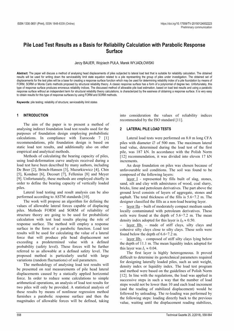
21 2 3( ) ,U P B B P B P err= + + + (12)
where U denotes lateral displacement of pile heads, P is the applied lateral force, Bi are parameters describing the parabola, and err represents a random matching error with the expected value equal to zero and a standard deviation se. A statistical analysis of the results was conducted by using non-linear regression software NLIN2 [16], which is based on a numerical algorithm employing so-called Marquardt’s compromise [17]. The aim of each of the discussed analyses was to obtain stochastic measures of variability existing in the obtained set of measurement results. In this case, the measure is the random matching error err from equation (12), with expected value equal to zero and standard deviation se, obtained in the process of determining Bi value. Values bi of parameters Bi describing regression model (12) are shown in Tab. 2.
Table 2 Values of parameters defining response surface OP Model b1 b2 b3 se
OP 0,169263 −0,0121964 0,0001467 0,450143
When the values of forces loading the pile, whose averaged (see Fig. 2) lateral head displacement is described by parabola OP, are regarded as deterministic quantities, all the stochastic variation of displacement U(P) is contained within standard deviation se of random matching error err. With this assumption, reliability index β is described by a simple relation:
( ),all
e
u U Ps
β−
= (13)
where uall equals 1 cm and displacement U(P) is defined by formula (12).
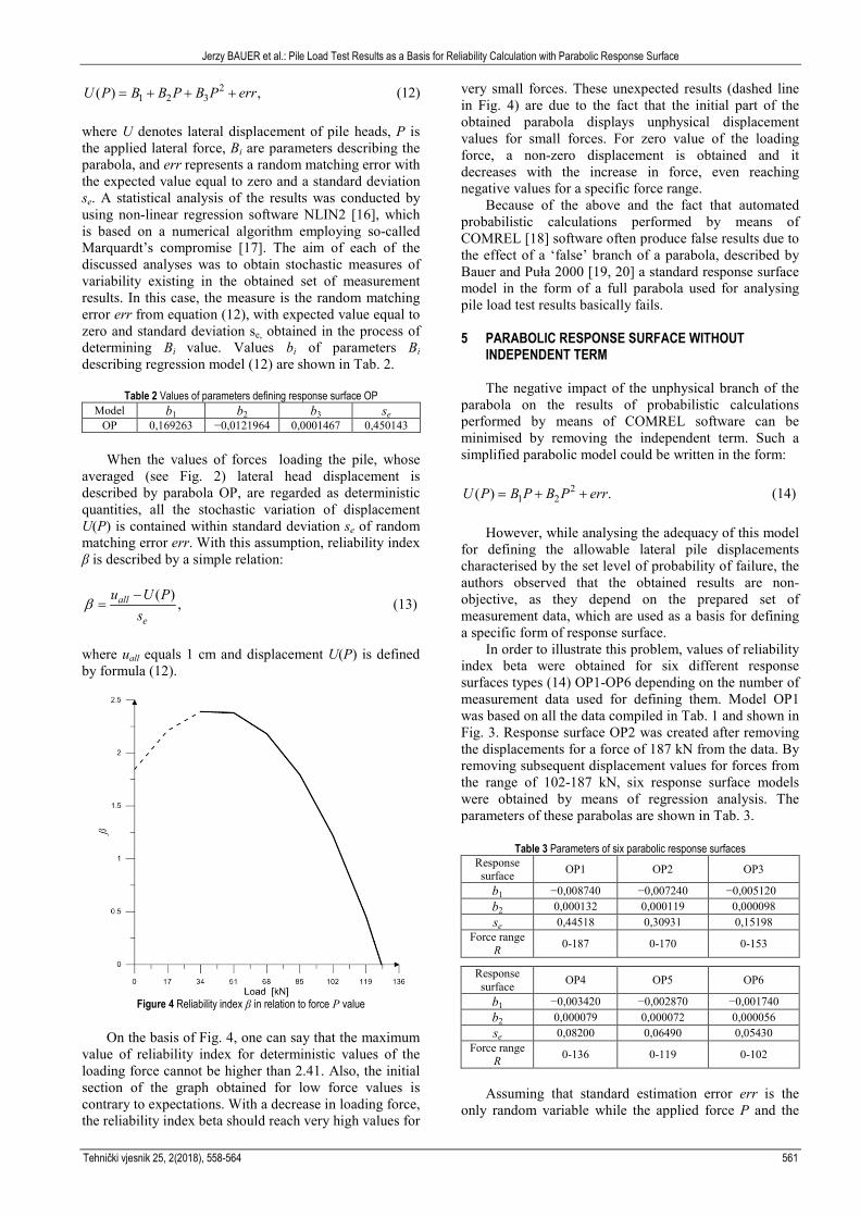
Figure 4 Reliability index β in relation to force P value
On the basis of Fig. 4, one can say that the maximum
value of reliability index for deterministic values of the loading force cannot be higher than 2.41. Also, the initial section of the graph obtained for low force values is contrary to expectations. With a decrease in loading force, the reliability index beta should reach very high values for
very small forces. These unexpected results (dashed line in Fig. 4) are due to the fact that the initial part of the obtained parabola displays unphysical displacement values for small forces. For zero value of the loading force, a non-zero displacement is obtained and it decreases with the increase in force, even reaching negative values for a specific force range. Because of the above and the fact that automated probabilistic calculations performed by means of COMREL [18] software often produce false results due to the effect of a ‘false’ branch of a parabola, described by Bauer and Puła 2000 [19, 20] a standard response surface model in the form of a full parabola used for analysing pile load test results basically fails. 5 PARABOLIC RESPONSE SURFACE WITHOUT
INDEPENDENT TERM The negative impact of the unphysical branch of the parabola on the results of probabilistic calculations performed by means of COMREL software can be minimised by removing the independent term. Such a simplified parabolic model could be written in the form:
21 2( ) .U P B P B P err= + + (14)
However, while analysing the adequacy of this model
for defining the allowable lateral pile displacements characterised by the set level of probability of failure, the authors observed that the obtained results are non-objective, as they depend on the prepared set of measurement data, which are used as a basis for defining a specific form of response surface.
In order to illustrate this problem, values of reliability index beta were obtained for six different response surfaces types (14) OP1-OP6 depending on the number of measurement data used for defining them. Model OP1 was based on all the data compiled in Tab. 1 and shown in Fig. 3. Response surface OP2 was created after removing the displacements for a force of 187 kN from the data. By removing subsequent displacement values for forces from the range of 102-187 kN, six response surface models were obtained by means of regression analysis. The parameters of these parabolas are shown in Tab. 3.
Table 3 Parameters of six parabolic response surfaces
Response surface OP1 OP2 OP3
b1 −0,008740 −0,007240 −0,005120 b2 0,000132 0,000119 0,000098 se 0,44518 0,30931 0,15198
Force range R 0-187 0-170 0-153
Response surface OP4 OP5 OP6
b1 −0,003420 −0,002870 −0,001740 b2 0,000079 0,000072 0,000056 se 0,08200 0,06490 0,05430
Force range R 0-136 0-119 0-102
Assuming that standard estimation error err is the
only random variable while the applied force P and the

Jerzy BAUER et al.: Pile Load Test Results as a Basis for Reliability Calculation with Parabolic Response Surface
562 Technical Gazette 25, 2(2018), 558-564
obtained parameters bi are deterministic parameters, all the stochastic variation inherent in the data set influences the expected value of this error. Tab. 3 indicates that the value of standard estimation error decreases almost tenfold when results characterized by the largest variability are removed from the data set.
Figure 5 Obtainable reliability indices β in relation to the employed response
surfaces
By using expression (14), one can obtain values of indices beta depending on the adopted response surface. Displacement U(P) and standard deviation se of error err found in this expression define the values in Tab. 3. The values of reliability indices beta depending on the adopted response surface models are shown in Figure 5. The graphs were based on an assumption that force is a deterministic variable. In the drawing, the abscissa of force is presented in disproportional scale in order to present the course of the graphs in the zone of non-physical displacement-force relation.
The drawing demonstrates that the range of reliability indices is highly dependent on the adopted response surface. This fact illustrates the non-objectivity of this method of allowable pile load estimation at the set reliability level. Using this method of load test data analysis may produce completely accidental values of allowable forces in the range 3-141 kN. They are shown in Tab. 4, where the last row contains allowable force values for the adopted response surface models, with the assumed value of reliability index beta at the level of 2.3. Table 4 Values of allowable loading force for reliability index β of 2.3, depending
on the adopted response surface Response surface OP1 OP2 OP3 OP4 OP5 OP6
Force range R (kN) 0-187 0-170 0-153 0-136 0-119 0-102
Allowable force (kN)
63,4 2,9 88,7 112,0 125,4 130,3 141,4
The second row in the table represents the force range
for which a particular response surface was obtained. One can observe that the determined value of allowable force is outside the force range used for defining response
surfaces OP5 and OP6. Additionally, there are two values of allowable forces for response surface OP1. The lower value is generated by the non-physical branch of the parabola with negative displacement values. The bar chart of these allowable forces is shown in Fig. 6.
Figure 6 Allowable force values depending on the adopted response surface
The obtained response surfaces OP1-OP6 may be
employed for engineering calculations after the discussed non-objectivity is eliminated while choosing the response surface for further calculations. Strength calculations consist of design calculations and determining the structure’s load capacity, i.e. the allowable loads. These calculations should be performed with the use of limit state method taking into account the limit state of bearing capacity and serviceability. The ISO Standard [11] for serviceability limit states recommends adopting reliability indices dependent on the consequences of a possible failure and the cost of repair. This recommendation is shown in Tab. 5. When highly ‘responsible’ structures using bearing capacity limit states are designed, the value of reliability index can be much higher (e.g. 7).
Table 5 Recommended values of reliability index β in limit states of serviceability, C – can be applied in ultimate limit states
Relative safety provision costs
Damage effects Minor Noticeable Moderate Heavy
Low 0 1,5 2,3 3,1 (C) Moderate 1,3 2,3 3,1 3,8 (C)
High 2,3 3,1 3,8 4,3 (C)
As an example of employing the obtained response surfaces, pile bearing capacities will be defined for the set level of probability of failure defined by the reliability indices recommended in Tab. 5. It was assumed in the calculations that a pile is loaded with a random force with lognormal distribution and a coefficient of variation wz of 15 percent.
The abovementioned non-objectivity occurring when creating a response surface can only be eliminated if limitations are introduced to remove arbitrariness while adopting a particular response surface for further calculations.
In problems related to engineering practice, lateral forces applied to pile heads are random forces. It is

Jerzy BAUER et al.: Pile Load Test Results as a Basis for Reliability Calculation with Parabolic Response Surface
Tehnički vjesnik 25, 2(2018), 558-564 563
usually assumed that they have lognormal distribution with coefficient of variation wz in the range of 0-15 percent. Thus, the response surface is defined by two random variables: force P and matching error err from equation (14). The matching error depends on the adopted response surface from Tab. 3.
The limitation which will make the choice of response surface objective is the inequality: P* ≤ R, (15) where P* is the maximum value of force at the design point, while R stands for the maximum applied test force P, for which a response surface in Tab. 3 was created. While using six response surfaces OP1-OP6 to define six values of force P*, we will notice that only some of them meet inequality (15). The sought value of allowable force is the one for which the highest associated value of P* meets inequality (15). In other words, the appropriate response surface is the one with the lowest R value used to define the P* meeting inequality (15). The choice of the allowable forces shown in Tab. 7 was based on the results compiled in Tab. 6.
Table 6 Values of allowable forces and forces associated with them at the design point
β OP3 OP4 Pall P* Pall P*
0 131 130.6 136 136.1 1,3 107 127,2 113 134,9 1,5 104 126,5 109 134,7 2,3 91 123,7 97 133,8 3,1 80 120,7 85 133,0 3,8 71 117,4 77 132,2 4,3 65 114,7 71 131,6
R = 153 kN R = 136 kN
The largest force P* meeting inequality (15) chooses the allowable forces printed in bold type, which have been used for creating Tab. 7.
Table 7 Values of allowable forces Pall defined for reliability indices recommended in Tab. 5
Relative safety provision costs
Damage effects Minor Noticeable Moderate Heavy
Low 1 109 97 85 Moderate 113 97 85 77
High 97 85 77 71
One should note that the allowable forces found in Tab. 7 were calculated from two different response surfaces OP3 and OP4 for variation coefficient wz = 15 percent. 6 CONCLUSIONS
Non-linear regression method, employed for analysing load tests results, suggests estimating approximation errors by means of one random variable with normal distribution. The expected value of matching error equals zero and the value of standard deviation is defined during the approximation process. The standard error deviation is constant in all the loading force range. Unfortunately, this constancy of standard estimation error transfers large displacement variation recorded for large loading forces onto low and medium force values.
Decreasing this transfer of stochastic variation from large loading force range to small forces by removing the results for large forces from data sets may lead to non-objectivity of the obtained probabilistic results.
Taking the above into account, the following conclusions referring to particular regression models could be drawn:
Regression model in the form of a full parabola with a classic approximation error, used for a complete set of measurement data, fails completely. During probabilistic calculations, there is a skip to an unphysical branch of the parabola and entirely wrong values of allowable forces are obtained.
Regression models in the form of a parabola with no independent term do not have ‘false’ branches, but the proper branch of a parabola can possess initial ranges with unphysical displacement values. This results in reliability index beta change trends contrary to expectations (the reliability index decreases for a decreasing force instead of growing). For higher values of loading forces, correct results are obtained. However, the obtained results of allowable forces are non-objective because of the fact that the approximation error, constant for the whole range of the loading force, transfers high statistical uncertainty from high values of loading forces to the low ones. Thus, removing subsequent displacement results for the highest loading force values from the calculations increases the values of the sought allowable forces. Unfortunately, this procedure leads to non-objectivity of the obtained values of allowable forces.
Limiting the parabolic model to one component eliminates the problem of the initial force range with unphysical displacement values, but this happens at the cost of the accuracy of displacement approximation.
A response surface model in the form of a parabola with no independent term can be modified by limiting stochastic variation transfer from the range of large forces onto that of small ones, as shown in models OP1-OP6. Ensuring an objective way of choosing a response surface for further calculations requires introducing limitations, e.g. meeting inequality (15).
The discussed method of allowable pile load estimation, based on load test results and using a parabolic response surface without an independent term for structural reliability theory calculations, is characterized by the easiness of obtaining a response surface. Additionally, it is very easy to obtain results for this type of response surfaces by using FORM and SORM methods employed by commercial software facilitating probabilistic calculations. 7 REFERENCES [1] EN 1997-1 :2008. Eurocode 7. Geotechnical Design. Part 1.
General Rules. CEN, Brussels. [2] De Beer, E. E. (1968). Proefondervindelijke bijdrage tot de
studie van het grensdraagvermogen van zand onder funderingen op staal. Tijgshift der Openbar Verken van Belgie, 4, 5 and 6.
[3] Hansen, B. J. (1963). Discussion on Hyberbolic Stress-Strain Response. ASCE Journal for Soil Mechanics and Foundation Engineering, 97(6), 931-932.
[4] Mazurkiewicz, B. K. (1972). Test Loading of Piles According to Polish Regulations. Royal Swedish Academy

Jerzy BAUER et al.: Pile Load Test Results as a Basis for Reliability Calculation with Parabolic Response Surface
564 Technical Gazette 25, 2(2018), 558-564
of Engineering Sciences Commission on Pile Research. Stockholm, Report No. 35.
[5] Chin, F. K. (1970). Estimation of the Ultimate Load of Piles Not Carried to Failure. Proc. 2nd Southeast Asia Conference on soil Engineering / Singapore, 81-90.
[6] Kondner, R. L. (1963). Hyberbolic Stress-Strain Response in cohesive soil. ASCE Journal for Soil Mechanics and Foundation Engineering, 89(1), 115-144.
[7] Decourt, L. (1999). Behaviour of foundations under working load conditions. Proceedings of the 11th Pan-American Conference on Soil Mechanics and Geotechnical Engineering / Foz DoIguassu, Brazil, Vol. 4, 453-488.
[8] Fellenius, B. H. (2001). What Capacity Value to choose from the Results of a Static Loading Test. The newsletter of the Deep Foundation Institute, Fulcrum, Deep Foundation Institute. New Jersey, 19, 19-22.
[9] Meyer, Z. (2014). Static load tests, short series interpretation. Studia Geotechnica et Mechanica, 36(2), 45-49.
[10] Standard test method for piles under lateral load. ASTM standard D3966–90. ASTM International, West Conshohocken, Pensylwania, United States, 1990.
[11] International Standard ISO 2394:2015. General principles on reliability for structures. International Standards Organisation, 2015.
[12] Polish Standard PN-B 02482:1983. Bearing capacity of piles and pile foundations.The Polish Committee for Standardization, 1983.
[13] Rackwitz, R. (1982). Response Surfaces in Structural Reliability. Berichte zur Zuverlässigkeitstheorie der Bauwerke. Laboratorium für den konstruktiven Ingenieurbau, Technische Universität München. Heft 67.
[14] Hochenbichler, M., Gollwitzer, S., Kruse, W., & Rackwitz, R. (1987). New light on first and second-order reliability methods. Structural Safety, 4, 267-284. https://doi.org/10.1016/0167-4730(87)90002-6
[15] Breitung, K. (1984). Asymptotic Approximations for Multinormal Integrals. J. Eng. Mech., 110(3), 357-366. https://doi.org/10.1061/(ASCE)0733-9399(1984)110:3(357)
[16] Marquardt, D. W. (1966). NLIN2 for least-squares estimation of non-linear parameters computer code. Distribution no. 309401. IBM Share Library, 77.
[17] Marquardt, D. W. (1963). An algorithm for least-squares estimation of non-linear parameters. J. Soc. Indust. Appl. Math., 11(2), 431-441. https://doi.org/10.1137/0111030
[18] STRUREL 2003. A structural reliability analysis program system COMRREL & SYSTREL: User’s Manual. RCP Consult, Germany, 2003.
[19] Bauer, J. & Puła, W. (2000). Reliability with respects to settlement limit-states of shallow foundation on linearly-deformable subsoil. Computers & Geotechnics, 25(3-4), 281-308. https://doi.org/10.1016/S0266-352X(99)00043-9
[20] Bauer, J. & Puła, W. (2000). Neural network supported response surface method with respect to reliability computations in geotechnics. Studia Geotechnica et Mechanica, 22(3-4), 103-115.
Contact information:
Jerzy BAUER, PhD Assistant Professor Faculty of Geoengineering, Geology and Mining, Wrocław University of Science and Technology, Na Grobli 15, 50-421 Wrocław, Poland [email protected]
Wojciech PUŁA, Professor Faculty of Civil Engineering, Wrocław University of Science and Technology Wybrzeże St. Wyspiańskiego 27, 50-370 Wrocław, Poland [email protected]
Marek WYJADŁOWSKI, PhD Assistant Professor Faculty of Civil Engineering, Wrocław University of Science Technology, Wybrzeże St. Wyspiańskiego 27, 50-370 Wrocław, Poland [email protected]