picologo micro plc editor user guide june 2013 · such as tmo-100 tetra modem, rtu-810 analog radio...
TRANSCRIPT

PicoLogo Micro PLC Editor PLE 2.00
User Guide
June 2013
Funk-Electronic Piciorgros GmbH
Claudiastrasse 5 51149 Cologne
Germany

Funk-Electronic Piciorgros GmbH PicoLogo Licensing Procedure
V0.1 page 2 of 34
1 INTRODUCTION...................................................................................................................... 3 1.1 Overview .............................................................................................................................. 3 1.2 Safety Precautions ................................................................................................................ 3 1.3 Disclaimer ............................................................................................................................ 3
2 PICOLOGO 4 2.1 What is PicoLogo? ............................................................................................................... 4 2.2 PicoLogo Applications – where and why to use PicoLogo ................................................. 4
3 INSTALLATION OF THE PICOLOGO EDITOR ............................................................... 5 3.1 Software needed ................................................................................................................... 5 3.2 Installation process............................................................................................................... 5 3.3 Hardware needed.................................................................................................................. 7
4 LICENSING 8 4.1 Licensed functionalities........................................................................................................ 8 4.2 Request a license .................................................................................................................. 8 4.3 Activate the editor with the received license key................................................................. 9
5 THE PICOLOGO WORKSPACE ......................................................................................... 10 5.1 PLE Screen after starting the program ............................................................................... 10 5.2 The Standard Tool Bar ....................................................................................................... 11 5.3 The Tools Tool Bar ............................................................................................................ 12 5.4 Selecting Logic Function Blocks ....................................................................................... 13 5.5 “On Mouse Over” Support................................................................................................. 14 5.6 Property Box ...................................................................................................................... 15
6 MY FIRST PICOLOGO PROJECT...................................................................................... 16 6.1 Designing a simple Logic................................................................................................... 16 6.1.1 Placing Logic Blocks on the Workspace.................................................................... 16 6.1.2 Wiring Logic Blocks on the Workspace .................................................................... 16 6.2 Testing the Logic in Simulation Mode............................................................................... 16 6.3 Compiling the Project and Transfer to the Target Device ................................................. 17 6.4 Online Monitoring the Logic inside the Target Device ..................................................... 17
7 LOGIC FUNCTIONS.............................................................................................................. 18 7.1 Contacts and Constants [CO] ............................................................................................. 18 7.2 Basic Functions [BF].......................................................................................................... 20 Special Functions [SF] .................................................................................................................... 21 7.3 Special Functions [SF2] ..................................................................................................... 24 7.4 Communication Functions [CF]......................................................................................... 26 Analog Functions [AF].................................................................................................................... 29
8 SAMPLE APPLICATIONS.................................................................................................... 30 8.1 Sending a Text Message..................................................................................................... 30 8.2 Sending different Text Messages ....................................................................................... 31 8.3 Monitoring the RSSI .......................................................................................................... 32 8.4 Overhead Tank Monitoring and Control ............................................................................ 33
9 SOFTWARE VERSIONS........................................................................................................ 34

Funk-Electronic Piciorgros GmbH PicoLogo Licensing Procedure
V0.1 page 3 of 34
1 Introduction
1.1 Overview
This document contains information about setup, settings, and operation of the PicoLogo Micro PLC (Micro Logic) and the PLE PicoLogo graphical editor.
1.2 Safety Precautions
The PicoLogo Micro PLC should not be used in life-supporting or life-critical applications or in safety systems without our prior written permission.
1.3 Disclaimer
We have carefully checked the content of this document, and the hardware and software described in it, for compatibility. However, we cannot exclude possibilities of deviations and cannot guarantee complete conformity of the document with the equipment it describes. If any corrections or improvements are to be made, they will be taken into consideration in the next version of this document. Important instructions are marked by the expressions "Important", "Note" or “Caution!”. These should be carefully observed. Explanations regarding these precautions can be found in the website www.TetraModem.com, in the Login Area.

Funk-Electronic Piciorgros GmbH PicoLogo Licensing Procedure
V0.1 page 4 of 34
2 PicoLogo
2.1 What is PicoLogo?
The PicoLogo MicroPLC is a soft logic that can operate on various Piciorgros products such as TMO-100 TETRA Modem, RTU-810 Analog Radio Modem combined with a GSM Modem and other products with or without embedded I/O. PicoLogo supports a wide range of functions like simple and complex logic gates for digital and analog values, text messaging with dynamic parameters, SNMP/Trap messaging, MMI (Man Machine Interface) the Modbus RTU- and also the IEC60870-5-101 protocol. PicoLogo is able to access all serial ports, all inputs and outputs, the Ethernet port (UDP) and also important status information and registers of the specific device it is operating on. And with the MMI, the Modbus and the IEC60870-5-101 protocol it is also possible to access digital or analog I/O from remote units or local connected third party devices like energy meters/counter, PLC’s, and smart devices like air-conditions, emergency power supplies and others. All of these fantastic features give the application engineer the freedom to take the simple data modem and make it a complex and unique SCADA device, exactly as needed for his customer or the specific application. PicoLogo consists of two parts, the PicoLogo Runtime Software and the PLE (PicoLogo Editor). The runtime is the software that executes the logic function(s) in the target device and the PLE editor is a powerful graphical design kit to develop, simulate, test and compile the logic and load it into the target device. The developed logics can be saved on disk, loaded to a target device locally or remotely by IP, or printed on a printer.
2.2 PicoLogo Applications – where and why to use PicoLogo
More that 80% of all wireless applications in Utilities, Water and Waste Water, Gas and Oil, Public Transportation, Oil and Gas Platform Operation, Airports and many more use PLC’s in expensive combination with an additional wireless (GSM, Analog Radio, TETRA, …) modem, where a simple water level, door contact, emergency power supply or similar applications have to be monitored. That is exactly the target for the embedded PicoLogo, an “All in One Solution” with Modem, embedded digital and analog I/O, serial and Ethernet ports and an embedded MicroPLC, easy to program, easy to maintain. But also infrastructure monitoring is a very interesting market. The power supply, environment temperature, level of the diesel tank for the emergency generation, RF filed strength, door contacts and others digital and analog signals can be monitored for TETRA, GSM and also for analog radio base stations.
Funk-Electronic Piciorgros GmbH PicoLogo Licensing Procedure
V0.1 page 5 of 34
3 Installation of the PicoLogo Editor
3.1 Software needed
The only software package is the “PLE2_setup.exe”, which is provided by the technical staff of the Funk-Electronic Piciorgros GmbH or can be downloaded from the homepage “http://www.piciorgros.com”. This package includes the complete editor with limited functionalities. To use all functions including the programming of target devices, the editor has to be registered. Important A registered version of the editor is bound to the used PC and cannot be transferred to another PC.
3.2 Installation process
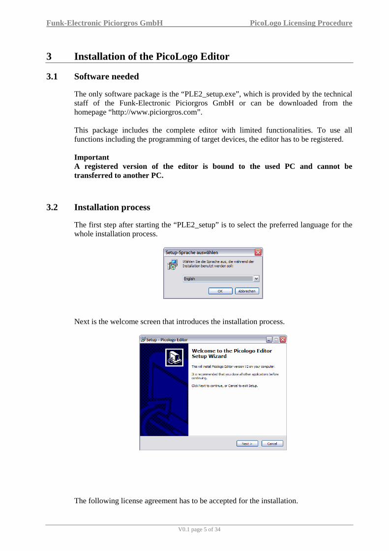
The first step after starting the “PLE2_setup” is to select the preferred language for the whole installation process.
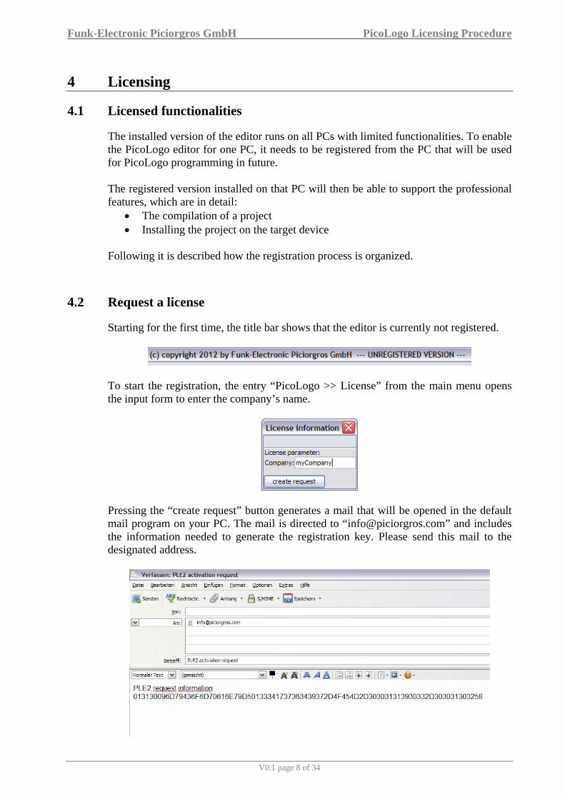
Next is the welcome screen that introduces the installation process.
The following license agreement has to be accepted for the installation.

Funk-Electronic Piciorgros GmbH PicoLogo Licensing Procedure
V0.1 page 6 of 34
With the next step the target folder for the installation can be selected. The “Browse…” button opens a location select dialogue. The required space on the disk is less than 10 MB.
The PicoLogo Editor will be available in the Start Menu. The current dialogue defines the name of the entry.
The last window summarizes all selected information from the inputs before. Press “Install” to finalize the preparation and initialize the installation.

Funk-Electronic Piciorgros GmbH PicoLogo Licensing Procedure
V0.1 page 7 of 34
The PicoLogo editor is now available in your Start Menu and can be started from there.
3.3 Hardware needed
Target devices for the PicoLogo editor can be the TMO-100 and the RTU-810. Only these two categories of devices support the latest PicoLogo functionalities. Please be aware that the firmware is updated before the device can be accessed with the editor. The target devices must also have the PicoLogo option enabled.
Funk-Electronic Piciorgros GmbH PicoLogo Licensing Procedure
V0.1 page 8 of 34
4 Licensing
4.1 Licensed functionalities
The installed version of the editor runs on all PCs with limited functionalities. To enable the PicoLogo editor for one PC, it needs to be registered from the PC that will be used for PicoLogo programming in future. The registered version installed on that PC will then be able to support the professional features, which are in detail:
• The compilation of a project • Installing the project on the target device
Following it is described how the registration process is organized.
4.2 Request a license
Starting for the first time, the title bar shows that the editor is currently not registered.
To start the registration, the entry “PicoLogo >> License” from the main menu opens the input form to enter the company’s name.
Pressing the “create request” button generates a mail that will be opened in the default mail program on your PC. The mail is directed to “[email protected]” and includes the information needed to generate the registration key. Please send this mail to the designated address.

Funk-Electronic Piciorgros GmbH PicoLogo Licensing Procedure
V0.1 page 9 of 34
If the PC is not able to send a mail, the request information is also stored to the clipboard. It can be written into a normal text file and then this file can be sent from any other PC that is able to send mails. Important The license must be requested from the PC that will be used for PicoLogo programming. A registered version of the editor is bound to this PC and cannot be transferred to another PC.
4.3 Activate the editor with the received license key
The support team of Funk-Electronic Piciorgros GmbH sends back the key information, which looks similar to the next picture.
This license key must be inserted in the editor at “PicoLogo >> license”. This form has changed its appearance and now expects the input of the license key information.
As soon as the key is inserted, the “activate license” button must be clicked to finalize the registration. The successful operation is announced with a following information window. The PicoLogo editor is now registered and can be used without restrictions. The license information can be seen at “PicoLogo >> license” from the main menu.

Funk-Electronic Piciorgros GmbH PicoLogo Licensing Procedure
V0.1 page 10 of 34
5 The PicoLogo Workspace
5.1 PLE Screen after starting the program

Funk-Electronic Piciorgros GmbH PicoLogo Licensing Procedure
V0.1 page 11 of 34
5.2 The Standard Tool Bar
Exit Program Before the schematics will be closed the program will ask if you want to save the data.
Close This function will close the schematics, but will not close the PicoLogo Editor
Save This function saves the current schematic that is seen on the current workspace. If several schematics are open at the same time, only the one on the active screen will be saved.
Print Function Will print the active schematics to any installed printer
Cut Functions Cut the selected objects to the Clip Board
Paste Function Pastes the content of the Clip Board to the screen
Undo Functions Undo the last action
Redo Functions Redo the last action
Compile the Schematics This function compiles the active (on screen) schematics into executable code for the target device
Load Project from PC to Target Device This function loads the compiled schematics into the target device

Funk-Electronic Piciorgros GmbH PicoLogo Licensing Procedure
V0.1 page 12 of 34
5.3 The Tools Tool Bar
Select Object Select objects to move them or to delete them Double click on the object to see (and change) its properties
Add Comments Click to any place on the drawing board to insert your text comments
Connect Blocks Use this tool to connect blocks. Connections can contain one output only but many inputs. Black lines indicate 1 Bit connections, blue line 16 bit connections.
Split Connect Links In complex schematics this feature can cut lines into two with references on each end of each line. That can result in a better impression of that schematic.
Constants and Connectors Select digital and analog in- and output blocks, connectors or constants and static high level or static low level
Basic Functions Select basic logic functions like AND, NAND, OR, XOR, NOR, INVERTER, 16 Bit AND, 16 BIT OR and BIT MONITOR … more …
Special Functions Select the Special Function bar: ONDELAY, OFFDELAY, ONOFFDELAY, ONDELAY (Edge Triggered), RANDOM CLOCK, WEEK TIMER, YEAR TIMER, SR FLIPFLOP, STAIRWAY FUNCTIONS, EVENT COUNTER, HOUR COUNTER, SCALE BLOCKS, DEV STATUS and VALUE INFORMATION … more …
Communication Functions MMI, Modbus RTU and IEC60850-5-101 functions as MODBUS READ, WRITE, MMI BITSET/RESET, MMI VALUE READ, ….. more ….
Analog Functions Select objects to move them or to delete them Double click on the object to see (and change) the properties
Switch to Simulation Mode This function sets the schematic to simulation mode. Active one bit lines can be seen in red color, and digital and analog values can be simulated by switches and analog sliders

Funk-Electronic Piciorgros GmbH PicoLogo Licensing Procedure
V0.1 page 13 of 34
5.4 Selecting Logic Function Blocks
Clicking the CO (contacts and constants) button will open and show all available logics for that specific group. Select one of these functions by clicking them and place them on the drawing board.
If all (some) blocks are placed, take the “Connect Blocks” tool and start wiring the schematic. The F11 key will switch on and off the block names and the F12 key switches on and off the pin number that would be used in the target device (see front label Inputs = A0…B15, Outputs = C0…C7, ….). Double clicking on a block that is placed on the drawing board will open the properties box for that specific block where different parameters can be set or changed.

Funk-Electronic Piciorgros GmbH PicoLogo Licensing Procedure
V0.1 page 14 of 34
5.5 “On Mouse Over” Support
Placing the mouse cursor over function blocks or the Tools Tool Bar will display some basic information that may be useful during the design of a logic. Also during the wiring of the logic blocks, the name or functional description of each block contact will be displayed, once the mouse cursor is placed over this contact or block. For more help or information place the mouse cursor over a block that is placed on the drawing board, click the right mouse button and select the Help function.

Funk-Electronic Piciorgros GmbH PicoLogo Licensing Procedure
V0.1 page 15 of 34
5.6 Property Box
The property box will appear with a double click on the particular logic block, or right clicking on it and then selecting Properties. The individual properties will be described later for each logic block
Funk-Electronic Piciorgros GmbH PicoLogo Licensing Procedure
V0.1 page 16 of 34
6 My first PicoLogo Project
6.1 Designing a simple Logic
6.1.1 Placing Logic Blocks on the Workspace
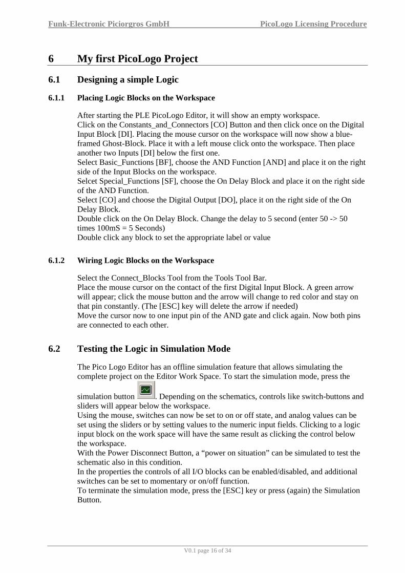
After starting the PLE PicoLogo Editor, it will show an empty workspace. Click on the Constants_and_Connectors [CO] Button and then click once on the Digital Input Block [DI]. Placing the mouse cursor on the workspace will now show a blue-framed Ghost-Block. Place it with a left mouse click onto the workspace. Then place another two Inputs [DI] below the first one. Select Basic_Functions [BF], choose the AND Function [AND] and place it on the right side of the Input Blocks on the workspace. Selcet Special_Functions [SF], choose the On Delay Block and place it on the right side of the AND Function. Select [CO] and choose the Digital Output [DO], place it on the right side of the On Delay Block. Double click on the On Delay Block. Change the delay to 5 second (enter 50 -> 50 times 100mS = 5 Seconds) Double click any block to set the appropriate label or value
6.1.2 Wiring Logic Blocks on the Workspace
Select the Connect_Blocks Tool from the Tools Tool Bar. Place the mouse cursor on the contact of the first Digital Input Block. A green arrow will appear; click the mouse button and the arrow will change to red color and stay on that pin constantly. (The [ESC] key will delete the arrow if needed) Move the cursor now to one input pin of the AND gate and click again. Now both pins are connected to each other.
6.2 Testing the Logic in Simulation Mode
The Pico Logo Editor has an offline simulation feature that allows simulating the complete project on the Editor Work Space. To start the simulation mode, press the
simulation button . Depending on the schematics, controls like switch-buttons and sliders will appear below the workspace. Using the mouse, switches can now be set to on or off state, and analog values can be set using the sliders or by setting values to the numeric input fields. Clicking to a logic input block on the work space will have the same result as clicking the control below the workspace. With the Power Disconnect Button, a “power on situation” can be simulated to test the schematic also in this condition. In the properties the controls of all I/O blocks can be enabled/disabled, and additional switches can be set to momentary or on/off function. To terminate the simulation mode, press the [ESC] key or press (again) the Simulation Button.

Funk-Electronic Piciorgros GmbH PicoLogo Licensing Procedure
V0.1 page 17 of 34
6.3 Compiling the Project and Transfer to the Target Device
Once the logic design is completed, it can be translated (compiled) into an executable format for the target device.
6.4 Online Monitoring the Logic inside the Target Device
Future extension

Funk-Electronic Piciorgros GmbH PicoLogo Licensing Procedure
V0.1 page 18 of 34
7 Logic Functions
7.1 Contacts and Constants [CO]
Digital Input Refers directly to the digital inputs of the device or the expansion modules
Digital Output Refers directly to the digital outputs of the device or the expansion modules
Analog Input Refers directly to the inputs of the device or the expansion modules.
Resolution 12 Bits Values 0 - 4095
Analog Output Refers directly to the analog outputs of the device or the expansion modules.
Resolution 12 Bits Values 0 - 4095
Static Low Function block to be used for static low level
Static High Function Block to be used for static High Level
Fix value Out (16) = Predefined value
Value can be changed via the web server
Reg Info Out (16) = Value of a specific device information

Funk-Electronic Piciorgros GmbH PicoLogo Licensing Procedure
V0.1 page 19 of 34
Bit Info Out (1) = Status of a specific device information

Funk-Electronic Piciorgros GmbH PicoLogo Licensing Procedure
V0.1 page 20 of 34
7.2 Basic Functions [BF]
AND Gate Q (high) = A and B and C
NAND Gate Q (low) = A and B and C
OR Gate Q (high) = A or B or C
XOR Gate Q (high) = A xor B xor C
NOR Gate Q (high) = NOT (A or B or C)
NOT Gate Q (high) = A (low)
AND16 Gate In (16) = Input value Clk (1) = Initiate operation with positive edge Rdy (1) = Operation ready indicator with positive edge Out (16) = (Input Value) AND (predefined Bit mask)
OR16 Gate In (16) = Input value Clk (1) = Initiate operation with positive edge Rdy (1) = Operation ready indicator with positive edge Out (16) = (Input value) OR (predefined Bit mask)
Funk-Electronic Piciorgros GmbH PicoLogo Licensing Procedure
V0.1 page 21 of 34
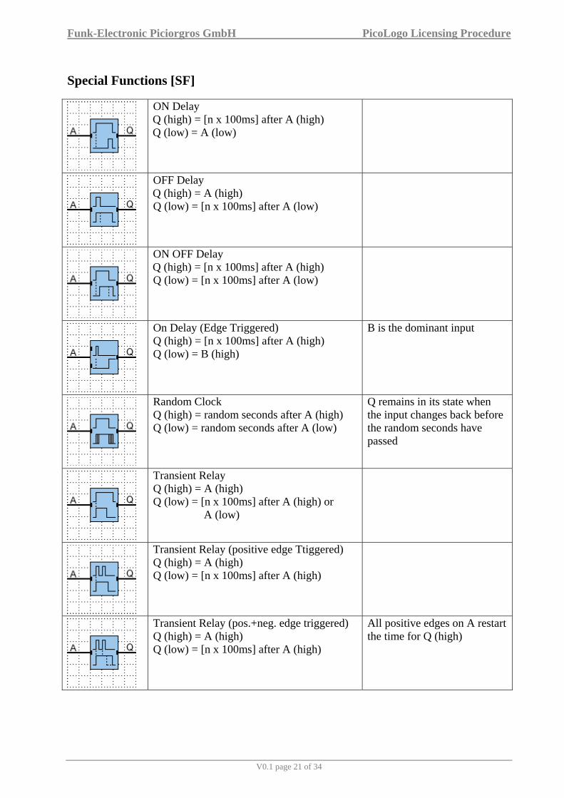
Special Functions [SF]
ON Delay Q (high) = [n x 100ms] after A (high) Q (low) = A (low)
OFF Delay Q (high) = A (high) Q (low) = [n x 100ms] after A (low)
ON OFF Delay Q (high) = [n x 100ms] after A (high) Q (low) = [n x 100ms] after A (low)
On Delay (Edge Triggered) Q (high) = [n x 100ms] after A (high) Q (low) = B (high)
B is the dominant input
Random Clock Q (high) = random seconds after A (high) Q (low) = random seconds after A (low)
Q remains in its state when the input changes back before the random seconds have passed
Transient Relay Q (high) = A (high) Q (low) = [n x 100ms] after A (high) or
A (low)
Transient Relay (positive edge Ttiggered) Q (high) = A (high) Q (low) = [n x 100ms] after A (high)
Transient Relay (pos.+neg. edge triggered) Q (high) = A (high) Q (low) = [n x 100ms] after A (high)
All positive edges on A restart the time for Q (high)

Funk-Electronic Piciorgros GmbH PicoLogo Licensing Procedure
V0.1 page 22 of 34
Asymmetric Clock Pulse Q toggles when A (high) with different time periods for (high) and (low) B (high) inverts Q
Symmetric Clock Pulse Q toggles with a fixed time period when A (high)
Weekly programmable Timer Switch Q (high) = Programmable weekdays, start and end time
3 independent parallel settings allowed
Yearly programmable Timer Switch Q (high) as soon as the programmed time interval is active
Stairway Light Switch Q (high) = A (high) Q (low) = [n x 1s] after A (high) Q drops for 1s programmable seconds before Q (low)
Extended Stairway Light Switch Q (high) = A (high) A (high) for short time: Q (low) = [n x 1s] after A (high) A (high) for long time: Q (low) = A (high) again
Event Counter Q (high) = Count value is equal or higher than the target value /Up (low) = count upwards /Up (high) = count downwards Res (high) = reset count value to 0
Counting limits are 0 … 65535
Hour Counter Q (high) = A (high) for [n hours] Q (low) = Oclr (high) or Res (high)
The reset via Oclr saves the hour counter

Funk-Electronic Piciorgros GmbH PicoLogo Licensing Procedure
V0.1 page 23 of 34
SR Flip Flop Q (high) = Set (high) Q (low) = Res (high)
Res is the dominant input
Latching Relay with Reset Input Q toggles with each edge of S/R Q (low) = Clr (high)

Funk-Electronic Piciorgros GmbH PicoLogo Licensing Procedure
V0.1 page 24 of 34
7.3 Special Functions [SF2]
16 Bit Shift register In (16) = Value to be shifted Clk (1) = Initiate operation with positive edge Rdy (1) = Operation ready indicator with positive edge Out (16) = Shifted value
Analog Multiplexer L (low): Out (16) = InA (16) L (high): Out (16) = InB (16)
Scaling Block In (16) = Original value Trg (1) = Initiate operation with positive edge Rdy (1) = Scaling ready indication (high) Out (16) = Scaled operation value
Min Hold Function (16 Bit) In (16) = Observed value Clr (1) = Restart operation Out (16) = Lowest detected value
First value of Out (16) is 0xFFFF
Max Hold Function (16 Bit) In (16) = Observed value Clr (1) = Restart operation Out (16) = Highest detected value
First value of Out (16) is 0
Bit-Mask (16 Bit) In (16) = Observed value Out (1) = Value of the selected bit
Bits are counted from 1 … 16
Monitor specific Bits In (16) = Observed value Clk (1) = Initiate operation with positive edge Rdy (1) = Change detected indication (high) Out (16) = Masked operation value
Rdy output is reset with the positive edge at Clk input
Comparison with reference value In (16) = Observed value Clk (1) = Initiate operation with positive edge Rdy (1) = Value has exceeded programmed threshold (high)

Funk-Electronic Piciorgros GmbH PicoLogo Licensing Procedure
V0.1 page 25 of 34
Compare analog values InA (16) = Observed value A InB (16) = Observed value B Out (1, high) = InA > (InB + programmed offset)
Mean Calculation of Analog Value In (16) = Observed value Rdy (1) = Indicated a valid output value Out (16) = Average value
Sample count and measurement interval can be programmed

Funk-Electronic Piciorgros GmbH PicoLogo Licensing Procedure
V0.1 page 26 of 34
7.4 Communication Functions [CF]
Send text message InA (1) = Initiate send operation with positive edge InB (1) = Send static message when (high) Rdy (1) = Message has been sent
A static message contains values from the first construction (eg. timing values)
Receive status Ind (1) = The programmed status has been received
Send status In (1) = Initiate send operation with positive edge Rdy (1) = Status has been sent
Modbus read control In (1) = Initiate send operation with positive edge Rdy (1) = Read operation finished Con = Connection to the related “Modbus read register” blocks
One control block can serve several register read blocks
Modbus read register Con = Connection to the related “Modbus read control” block In (1) = Fetch the current value with positive edge Rdy (1) = Read operation finished Out (16) = read register value
The corresponding read control block has to be triggered first to get current values
Modbus read IEEE754 value Con = Connection to the related “Modbus read control” block In (1) = Fetch the current value in IEEE754 format with positive edge Rdy (1) = Read operation finished Out (16) = calculated register value
The corresponding read control block has to be triggered first to get current values
Modbus write control In (1) = Initiate send operation with positive edge Con = Connection to the related “Modbus write register” blocks
One control block can serve several register write blocks
Modbus write register Con = Connection to the related “Modbus write control” block In (16) = Value to write in register Rdy (1) = Write operation finished
The corresponding write control block has to be triggered first to get current values
Funk-Electronic Piciorgros GmbH PicoLogo Licensing Procedure
V0.1 page 27 of 34
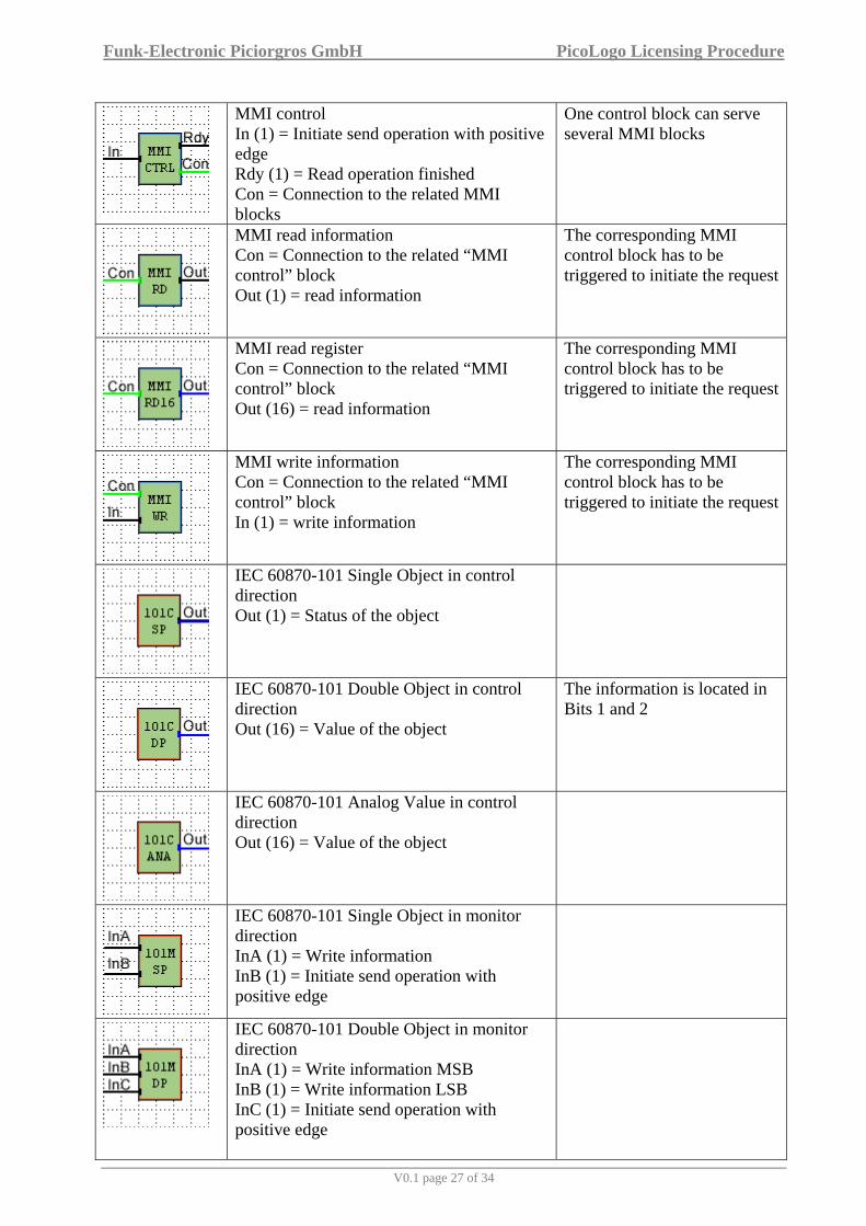
MMI control In (1) = Initiate send operation with positive edge Rdy (1) = Read operation finished Con = Connection to the related MMI blocks
One control block can serve several MMI blocks
MMI read information Con = Connection to the related “MMI control” block Out (1) = read information
The corresponding MMI control block has to be triggered to initiate the request
MMI read register Con = Connection to the related “MMI control” block Out (16) = read information
The corresponding MMI control block has to be triggered to initiate the request
MMI write information Con = Connection to the related “MMI control” block In (1) = write information
The corresponding MMI control block has to be triggered to initiate the request
IEC 60870-101 Single Object in control direction Out (1) = Status of the object
IEC 60870-101 Double Object in control direction Out (16) = Value of the object
The information is located in Bits 1 and 2
IEC 60870-101 Analog Value in control direction Out (16) = Value of the object
IEC 60870-101 Single Object in monitor direction InA (1) = Write information InB (1) = Initiate send operation with positive edge
IEC 60870-101 Double Object in monitor direction InA (1) = Write information MSB InB (1) = Write information LSB InC (1) = Initiate send operation with positive edge

Funk-Electronic Piciorgros GmbH PicoLogo Licensing Procedure
V0.1 page 28 of 34
IEC 60870-101 Analog Value in monitor direction InA (16) = Write information InB (1) = Initiate send operation with positive edge
IEC 60870-101 Counter Value in monitor direction InA (16) = Write information InB (1) = Initiate send operation with positive edge

Funk-Electronic Piciorgros GmbH PicoLogo Licensing Procedure
V0.1 page 29 of 34
Analog Functions [AF]
Analog level switch In (16) = Operation input value Out (1) = Operation result
Analog adder InA (16) = Operation input value InB (16) = Operation input value InC (16) = Operation input value Out (1) = (high) when (InA + InB) > (InC + programmable parameter)
Funk-Electronic Piciorgros GmbH PicoLogo Licensing Procedure
V0.1 page 30 of 34
8 Sample Applications
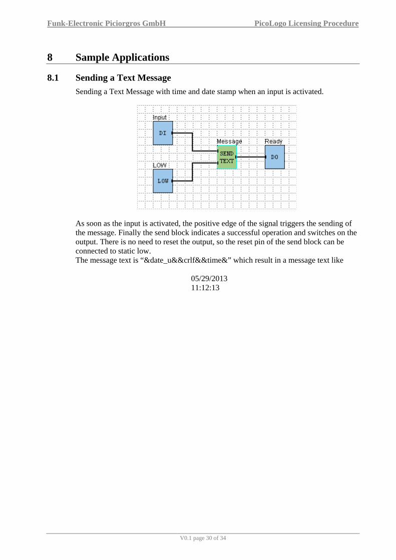
8.1 Sending a Text Message Sending a Text Message with time and date stamp when an input is activated.
As soon as the input is activated, the positive edge of the signal triggers the sending of the message. Finally the send block indicates a successful operation and switches on the output. There is no need to reset the output, so the reset pin of the send block can be connected to static low. The message text is “&date_u&&crlf&&time&” which result in a message text like
05/29/2013 11:12:13

Funk-Electronic Piciorgros GmbH PicoLogo Licensing Procedure
V0.1 page 31 of 34
8.2 Sending different Text Messages Sending a text message when an analog value is below a reference level one, and another text message when the analog level is above reference level two.
Same as in sample 1, but here the send blocks are triggered from a ANADIFF block. These blocks compare two values and as soon as the value on the upper pin is above the other value, their output becomes high. The DELON block in between this connection makes sure that the condition is valid for at least 3 seconds before the message is sent. The levels for switching are defined in the FIX VALUE blocks and can be edited even via the target devices web server at “PicoLogo >> Variables”.

Funk-Electronic Piciorgros GmbH PicoLogo Licensing Procedure
V0.1 page 32 of 34
8.3 Monitoring the RSSI Monitoring the RSSI (Field Strength Level) and sending a text message when the level is below a reference (min) value. Additional sending an OK-message every day at 10:00 AM, and a power on message (on power on only).
The scenario consists of three parts:
• If the field strength level drops under a certain limit (FIX VALUE block) the “MessageFS” block is triggered.
• The CLK block triggers the “MessageOK” block daily at 10 am • As soon as the device starts, the constant high level triggers the “MessageStart”
block. The ON DELAY block manages that the device has enough time for the startup to connect to the network

Funk-Electronic Piciorgros GmbH PicoLogo Licensing Procedure
V0.1 page 33 of 34
8.4 Overhead Tank Monitoring and Control Reading the analog level of a remote device every 5 minutes using the Modbus protocol. If the analog value is below “reference level one”, switch on a local output (pump). While the pump is operating, read the remote device every 15 seconds until the analog value is above “reference level two”, then switch off the local output (pump).
The project contains two impulses (5 minutes and 15 seconds) which are constantly running. With a logical combination, the information about the pump activity is used to select the needed clock cycle. The cycle then triggers a Modbus read operation for one register. The read value will be available at the output of the “MBread” block. During further operation, this value is compared to LevelOne and LevelTwo, which decide if the pump is activated or not.

Funk-Electronic Piciorgros GmbH PicoLogo Licensing Procedure
V0.1 page 34 of 34
9 Software Versions
The software (firmware) versions and document editions history is listed below:
Firmware Version
Document Version
Comments / Changes
2.00beta 2.00b Fist 2.00 Beta. Trial version only for selected customers