multi-rtu modbus modem v1automationresearchlabs.com/data monitoring...
TRANSCRIPT

MULTI RTU MODBUS MODEM USER GUIDE V1.07 KUROLIKAR AUTOMATION RESEARCH LABS PVT LTD
1
User manual
MULTI-RTU MODBUS MODEM
V1.07
UASAGE NOTICE
This software / document / material are property of Kurolikar Automation Research Labs
(KARL PL) Pvt Ltd. It has been provided for the exclusive use of customers for the products
of KARL PL. It must not be copied, saved or duplicated in full or in part in any form without
the written permission of KARL PL. Unauthorized copying, duplication or reproduction of
this material is restricted and may attract severe legal penalties.
The specifications and features mentioned in this document are available at the time this
document was prepared. Utmost care has been taken to maintain accuracy and consistency
of the information. However KARL PL does not guarantee this document to be free from
errors and use of the information is at sole responsibility of the user. KARL PL reserves the
right to change or modify this document at any time without prior notice.
MULTI RTU MODBUS MODEM USER GUIDE V1.07 KUROLIKAR AUTOMATION RESEARCH LABS PVT LTD
2
INDEX
INTRODUCTION
a. GSM / GPRS features
b. Data monitoring features
c. Applications
GETTING STARTED
a. String format of uploaded data
b. Connection pin-out
c. Wiring diagram
MODEM CONFIGURATION
a. Configuration commands
b. Getting information from modem
c. Acknowledgement from server
APPENDIX
a. Error codes
b. Troubleshooting notes

MULTI RTU MODBUS MODEM USER GUIDE V1.07 KUROLIKAR AUTOMATION RESEARCH LABS PVT LTD
3
INTRODUCTION
Product:Modbus master modem
Applicable product version: V3.34
Data collection interface: MODBUS master over RS485 half duplex / RS232 full duplex
Data uploading interface: TCP/IP over GPRS
The Modbus-modem is MODBUS master that collects information from connected
MODBUS RTUdevices over RS485 bus and sends tomapped server over GPRS. For reliable
data uploading to server, the modem sends data only if sufficient signal strength is
available. It also implements retry of data upload and packet based handshaking to make
sure that every data packet is successfully delivered to the server.
There are various product configurations available to meet varying application needs.
Multi-RTU modem can address up to 24 devices in round robin fashion. If there are less
than 24 devices on the network, user can set the actual number of devices on bus using
configuration command. In such case the number of registers per device can be more than
the default 16.
‘Automation Research Labs’ manufactures different models of such modems. These
various models of modems are designed in such a way that a completely heterogeneous
system can be implemented. A single data acquisition system can consist of some single-
RTU modems, some multi-RTU modems, some data logger modems, some direct IO
modems and some plain GSM modems. This enables customers to choose the right modem
for their application and save costs. This also enables the server side software developers
to write seamless interface libraries for parsing and saving the received data in database.
GSM/GPRS Features:
Based on Quectel quad band GSM/GPRS module. Supports TCP/IP Protocol. Quad band 850/900/1800/1900MHz. Class 12 multi-slot GPRS (up to 85.6Kbps data speed) 3V SIM card slot. Works with off-the-shelf available 50E antenna.
Data Monitoring Features:
Act as Modbus master over half duplex RS485 bus. (RS232 interface option available when only one RTU is to be connected)
Multi RTU, multi slot and multi registers per RTU.
Can fetch up to 16modbus registers per request frame.

MULTI RTU MODBUS MODEM USER GUIDE V1.07 KUROLIKAR AUTOMATION RESEARCH LABS PVT LTD
4
24 frame slots available for configuration. If all frames are configured for same RTU, a total of 384 registers can be fetched from single RTU
If all frames are configured for different RTUs, 24 RTU devices can be connected to modem and 16 registers of each RTU can be fetched.
Fully field configurable using simple SMS with access restriction feature. Only authorized users can configure the modem.
Data read frequency, Destination IP address, and Destination phone number for SMS,diagnostic SMS configurable from predefined mobile number.
Handles all AT commands internally. No need to write AT commands in external device.
Supports one primary and one redundant server IP. Two servers can be independently enabled or disabled for data uploading
Transmits data to server over GPRS when strong GPRS signal is available.
Built in RTC for keeping track of time. (Built in battery for RTC is optional. If user has non-interruptible power source for modem, internal battery is not required and still RTC can be utilized. Otherwise user has option to disable RTC feature.)
Built in memory for saving data temporarily. If GPRS connectivity is lost for longer duration, data is saved in battery backed internal memory. This data is uploaded to server when connectivity is resumed.
General product features:
Industry grade product. Standard industrial SMPS of 12V or 24V can be used for powering the modem
Designed for 24x7 application. Enclosed in attractive aluminum casing with powder coating. Covered under warranty for a period of 12months. (Refer warranty statement)
Applications:
Energy meter monitoring, AMR applications.
Monitoring product data from PLC / SCADA systems.
Monitoring custom devices having RS485 interface
Elevators / Gensets status reporting and maintenance.
Remote Maintenance of equipments.
Many more…..

MULTI RTU MODBUS MODEM USER GUIDE V1.07 KUROLIKAR AUTOMATION RESEARCH LABS PVT LTD
5
GETTING STARTED
Supported power supply range is 7.5VDC to 24VDC. Power source should be capable of sourcing minimum of 1A current.
Make sure to connect stable power supply to modem with specified polarity.
Wrong power supply connections (reverse polarity) for long duration may permanently damage modem.
Make sure that the SIM card has enough memory space free to receive messages. It is also recommended to take backup of important SMS on separate device. Modem will delete SMS from SIM card to free some space to receive new SMS.
Make sure that the SIM card has GPRS and SMS services activated.
Supported service providers for GPRS are Airtel, Uninor, Idea, BSNL. (May work with other service providers but not tested for GPRS data connectivity) Product version 3.20 onward supports dynamically adding support for new SIM cards.
Communication settings are as below Baud rate: Settable as 4800, 9600, 19200, 38400, 57600 (Factory default is
9600)
Start bit: 1
Data bits: 8 (LSB sent first)
Parity: Even
Stop bit: 1
Error Checking: 16 bit CRC
MODBUS register address size: 16bit
MODBUS register data size: 16bit
MODBUS Framing
String format of uploaded data Modem uploads all collected data to server device by device. Each data frame is a
ASCII string in following format. A separate frame is sent for every device.
<DEVICE ID>, [DATE / TIME,]<Comma separated data values><CR>
DEVICE ID – ID of MODBUS RTU device to which the data string belongs

MULTI RTU MODBUS MODEM USER GUIDE V1.07 KUROLIKAR AUTOMATION RESEARCH LABS PVT LTD
6
DATE/TIME –If modem is equipped with built-in battery, provides date and time of
data read from RTU device. If no battery support is available, RTC will lose date and
time upon power loss. In such case user may disable the RTC feature. When
disabled, date/time value is empty in the uploaded data string. When enabled and
preset to proper value, the data string contains real date and time.
Comma separated data values – Data values for each register is a 16bit number
received from RTU device. Every register data is decimal converted to ASCII
equivalent and the end software must multiply it by suitable scaling factor
applicable for that particular register. All data are comma separated numbers as
shown in below example.
Example1: Without date time string
Whenfirst two frame slots are configured for RTU device having id 28 and third
frame slot is configured for RTU device having id 56, the response to the serveris as
shown below. In this case the modem’s id is set to 5 and frame slot count is set to 3
M05-28A,<SPACE>,544,19,8751,2894<CR>
M05-28B,<SPACE>,5644,15,8851,2594<CR>
M05-56A,<SPACE>,5644,15,8851,2594<CR>
Example2: With date time string
M05-28A,01/11/2013 14:45:32,544,19,8751,2894<CR>
M05-28B,01/11/2013 14:45:32,5644,15,8851,2594<CR>
M05-56A,01/11/2013 14:45:32,5644,15,8851,2594<CR>
Color notations:
Blue: Information source. Number followed by M is modem ID
Black: Date and time in dd/MM/yyyy HH:mm:ss format
Green: Data received from RTU
Brown: Termination character, ASCII code for CARRIAGE RETURN
Purple: one SPACE
MULTI RTU MODBUS MODEM USER GUIDE V1.07 KUROLIKAR AUTOMATION RESEARCH LABS PVT LTD
7
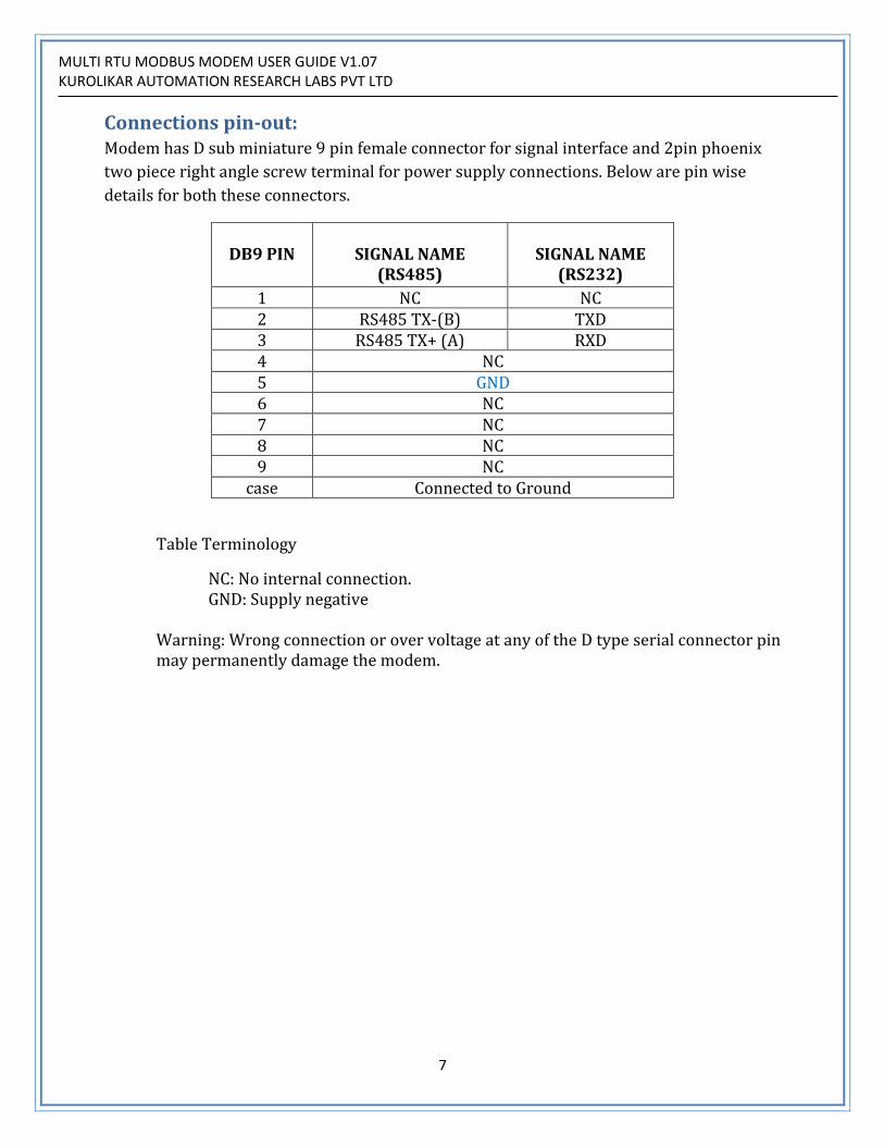
Connections pin-out: Modem has D sub miniature 9 pin female connector for signal interface and 2pin phoenix
two piece right angle screw terminal for power supply connections. Below are pin wise
details for both these connectors.
DB9 PIN
SIGNAL NAME
(RS485)
SIGNAL NAME
(RS232)
1 NC NC 2 RS485 TX‐(B) TXD 3 RS485 TX+ (A) RXD 4 NC 5 GND 6 NC 7 NC 8 NC 9 NC
case Connected to Ground
Table Terminology
NC: No internal connection. GND: Supply negative
Warning: Wrong connection or over voltage at any of the D type serial connector pin may permanently damage the modem.
MULTI RTU MODBUS MODEM USER GUIDE V1.07 KUROLIKAR AUTOMATION RESEARCH LABS PVT LTD
8
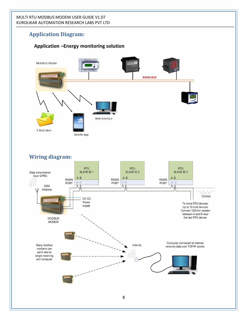
Application Diagram:
Wiring diagram:

MULTI RTU MODBUS MODEM USER GUIDE V1.07 KUROLIKAR AUTOMATION RESEARCH LABS PVT LTD
9
It is also recommended to connect ground of all devices on the RS485 bus together to avoid
current loops. Modbus modem has ground available on pin 5 of DSUB connector.
MULTI RTU MODBUS MODEM USER GUIDE V1.07 KUROLIKAR AUTOMATION RESEARCH LABS PVT LTD
10
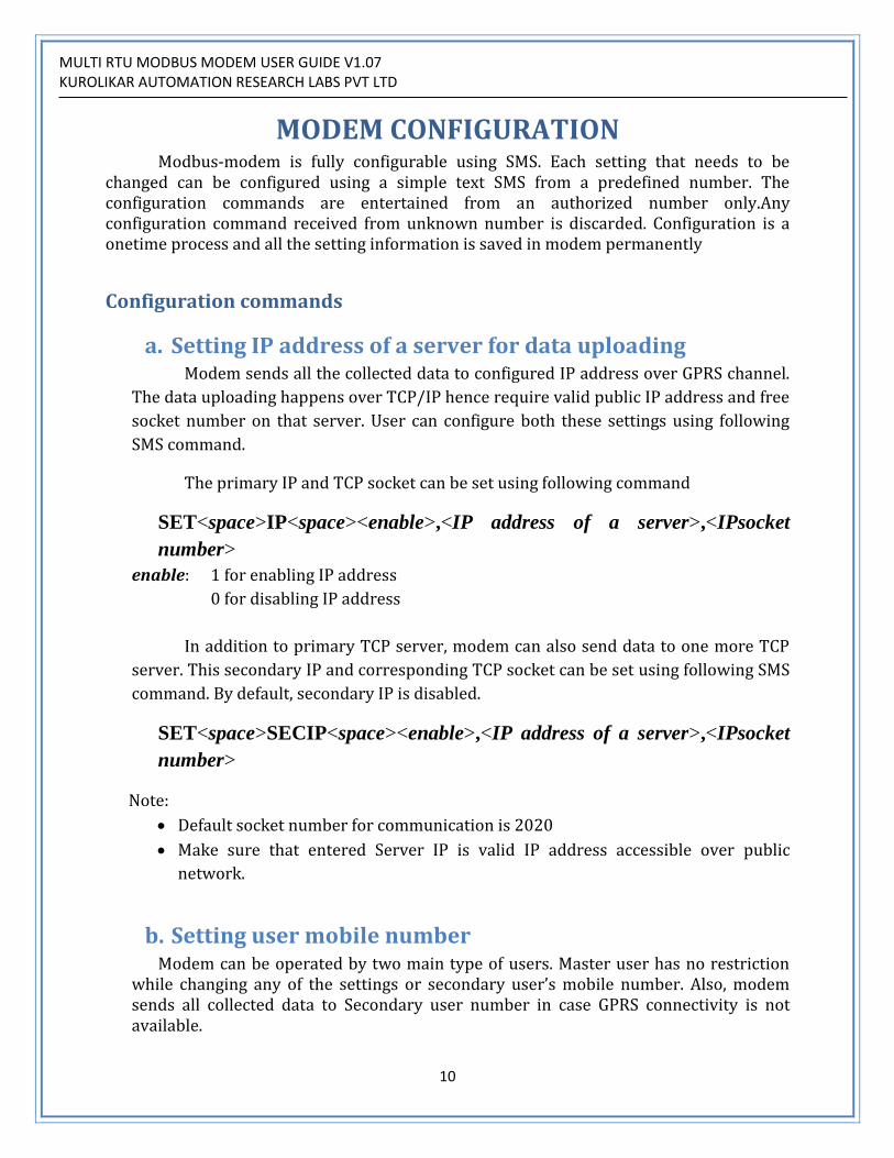
MODEM CONFIGURATION Modbus-modem is fully configurable using SMS. Each setting that needs to be
changed can be configured using a simple text SMS from a predefined number. The configuration commands are entertained from an authorized number only.Any configuration command received from unknown number is discarded. Configuration is a onetime process and all the setting information is saved in modem permanently
Configuration commands
a. Setting IP address of a server for data uploading Modem sends all the collected data to configured IP address over GPRS channel.
The data uploading happens over TCP/IP hence require valid public IP address and free
socket number on that server. User can configure both these settings using following
SMS command.
The primary IP and TCP socket can be set using following command
SET<space>IP<space><enable>,<IP address of a server>,<IPsocket
number>
enable: 1 for enabling IP address
0 for disabling IP address
In addition to primary TCP server, modem can also send data to one more TCP
server. This secondary IP and corresponding TCP socket can be set using following SMS
command. By default, secondary IP is disabled.
SET<space>SECIP<space><enable>,<IP address of a server>,<IPsocket
number>
Note:
Default socket number for communication is 2020
Make sure that entered Server IP is valid IP address accessible over public
network.
b. Setting user mobile number Modem can be operated by two main type of users. Master user has no restriction
while changing any of the settings or secondary user’s mobile number. Also, modem sends all collected data to Secondary user number in case GPRS connectivity is not available.

MULTI RTU MODBUS MODEM USER GUIDE V1.07 KUROLIKAR AUTOMATION RESEARCH LABS PVT LTD
11
Mobile number of master user can be changed using following command. Note that, this command can be used by existing master only. Any other user cannot change this setting. Master user has permission to change all other settings as well as own and secondary user’s mobile number.
SET<space>MASTER<space><mobile number>
Mobile number of secondary user can be set using following SMS command. Secondary user can modify all the settings related to modbus communication and server. This command can be used only by master user.
SET<space>RS<space><mobile number>
Note:
Make sure that entered mobile number is valid number.
Mobile number is a 10 digit number. Country code should not be included.
c. Setting Data upload Interval Time: Modem sends all collected data to server at every configured interval time. This time
is user selectable from 2minutes through 150minutes. Factory default setting time is 30
minutes. Interval time should not be greater than 150 minutes or less than 2minutes.
If user set data frequency larger than 150minutes, auto-modem sends data at
maximum default interval of 150min. If user set data frequency less than 2minutes,
modem sends data at minimum default interval of 2minutes.
User can set data frequency using following SMS command. The interval specified
should be in seconds.
SET<space>UPLOADFREQ<space><Data Frequency in minutes>
d. Setting data collection interval time Modem collects data from all configured RTU devices at specified interval. This
interval is in seconds and can be configured using following command. The polling time
can be as low as 3seconds and up to 3000 seconds. Default setting for this interval is
30seconds. This time must be in synchronism with data upload frequency. For example,
if data upload frequency is set to 3minutes and collection interval is set to larger than
180 seconds, modem may not have data available during each upload event.
SET<space>COLLINTVRL<space><Interval time in seconds>

MULTI RTU MODBUS MODEM USER GUIDE V1.07 KUROLIKAR AUTOMATION RESEARCH LABS PVT LTD
12
e. Setting RTC Time This is optional feature. This command will work only if your product model
supports it.Time and date stamp appears in data string transmitted to server.User can
set time and date using following SMS command. Since the command is being issued
using SMS, the time at which it gets delivered to modem is not guaranteed. Hence the
accuracy of time being set in modem cannot be guaranteed. It is recommended to
consider this delay approximately while issuing this command.
SET<space>TIME<space><DD/MM/YYYY><space><HH:MM:SS>
Note: Single space cannot be replaced by multiple spaces.
Specified time is in 24hour format
f. Enable RTC This command is used to make Time and date stamp appear in data string
transmitted to server.
RTC<space>ENABLE
g. Setting number of active frame slots A frame slot corresponds to Modbus command frame sent over RS485 bus. Although
there are 24 frame slots available, it is not necessary to configure and use all of them. In case of Multi-RTU Modbus-modem, this command sets the number of active frame slots. This command must be issued before configuring frame slots.
SET<space>SLOTCNT<space><number of active frame slots>
E.g. SET SLOTCNT 7
Above command will set first 7 frame slots to active state. Any frame configurations in remaining slots will remain unchanged but will be ignored by modem. The number specified in this command should be valid from 1 through 24. If any other number is specified, the command will be ignored and previous setting will remain unchanged.
h. Configuring Modbus Frame Slot Entry A frame slot entry contains device id of RTU, the starting address of register range,
number of registers from the starting address, function code to be used while building
the Modbus request frame and desired SMS status. This product supports fetching of up

MULTI RTU MODBUS MODEM USER GUIDE V1.07 KUROLIKAR AUTOMATION RESEARCH LABS PVT LTD
13
to 16 Modbus registers per request. If user requires more number of registers from any
RTU device, more than one entry can be made in frame slots for that RTU device.
Function code is also configurable for each slave. Only two function cods are
currently supported by modem which are read output registers (Function code 3) and
read input registers (function code 4). User should check in the RTU device manual
about the function code to be used for fetching any particular register range.
If modem can not send data over TCP/IP channel, data of particular RTU will be sent
using SMS if that option is enabled for that particular RTU. Default setting for this
option is disabled.
SMS command for this is as below
SET<space>SID<space>< FRAME SLOT SEQ>,<RTU
ID>,<StartAddress>, <Number of registersto read>, <Function
Code>,<Enable/Disable SMS>
FRAME SLOT SEQ = Sequence of register group in case of single-RTU Modbus
modem (Can be 1 through24)
RTU ID = ID of RTU device in case of multiple RTU Modbus modem (Can be 1
through 247)
Start Address= Address of first register in register range being fetched
For Enable SMS use code 1, for disable SMS use code 0
The following examples illustrate use of this command.

MULTI RTU MODBUS MODEM USER GUIDE V1.07 KUROLIKAR AUTOMATION RESEARCH LABS PVT LTD
14
1. E.g. SET SID 1,41,1023,10,3,0
Example 1 sets first frame slot entry (as shown in table) to read 10 registers from a RTU device having RTU ID 41. Address of first register in the range is 1023 and the function code being used is 3. SMS status is disabled, hence if modem fails to send this frame data to server, it will not be sent using SMS. In such a case, the data gets lost permanently
2. E.g. SET SID 2,78,45,4,4,1
Example 2 sets second frame slot entry to read 4 registers from a RTU device having RTU ID 78. Address of first register in the range is 45 and the function code being used is 4. SMS status is enabled, hence if modem fails to send this frame data to server, it will send the same to secondary user’s mobile number.
Note: RTU ID should be from 1 through 147 Start address is address of the first register in the desired register range. Number of registers should not be greater than 16. If specified more than 16, a
default setting of 16 registers is used. A separate SMS need to be sent for updating each frame slot entry. A total of 24
SMS will be required if all the slot entries are being configured.
i. Setting modem ID This command sets unique identifier for every Modbus modem. This way,
software can uniquely identify the modem from which the data is being received. If
the software can accept multiple client connection over TCP/IP, multiple modems can
connect to single server and send data to it.
User can set modemID using following SMS command -
SET<space>DEVICEID<space><Modem ID>
Note:
ModemID can be 1 through 20000. Factory default identifierfor modem is 1
j. Changing baud rate of modbus communication This command can be used for changing the communication speed over Modbus interface. It is required that all the devices connected over RS485 bus support the communication baud specified here. Hence make sure to select setting which is also supported by other devices.

MULTI RTU MODBUS MODEM USER GUIDE V1.07 KUROLIKAR AUTOMATION RESEARCH LABS PVT LTD
15
SET<space>BAUD<space><Desired baud rate>
Note:
Supported baud rate are 1200, 2400, 4800, 9600, 19200, 38400 and 57600. Factory default setting is 9600 Parity is also settable even, odd, none
k. Setting Parity of modbus communication This command can be used for changing the parity of communication over Modbus
interface. It is required that all the devices connected over RS485 bus support the
same parity selected here. Hence make sure to select setting which is also supported
by other devices.
SET<space>PARITY<space><Desired parity>
e.g. SET PARITY EVEN
Note:
Supported parity are EVEN ,ODD ,NONE Factory default setting is NONE
Fetching Information from Modem
a. Reading top level configuration of modem By sending following SMS user gets top level settings saved in auto-modem
GET<space>SETTINGS
The information received using this command is
IP Address of the server TCP Port (socket) number Status of TCP connectivity (enable / disable) Mobile number (master) which will receive data when GPRS data upload fails.
This number can also be used for configuring the modem. Mobile number (configure) which is used only for configuration of the modem Number of frame slots currently enabled. Modem ID
MULTI RTU MODBUS MODEM USER GUIDE V1.07 KUROLIKAR AUTOMATION RESEARCH LABS PVT LTD
16
b. Reading settings for particular frame slot By sending following SMS user gets settings of a particular RTU unit or particular
register range/frame.
GET<space>SIDSETT<space><FRAME SLOT NUMBER>
E.g. GET SIDSETT 3
The above example gives current configuration of RTU unit having device ID 3 in case of
multi-RTU Modbus modem. The information contained in the response is
RTU device ID
Register start address
Number of registers
Function code
SMS messaging enable/disabled status
c. Getting Data from modem MODBUS modem can send data through SMS on user’s request. By sending following
SMS,data of a particular RTU device can be received as reply to the SMS. The command string is as below
GET<space>DATA<space><FRAME SLOT SEQ>
Frame slot sequence can be 1 through 24 Note: Single space cannot be replaced by multiple spaces
Acknowledgement from server For a reliable communication, every data packet received by server can be
acknowledged by server. This feature is optional for multi-RTU modem and can be enabled
if required. If enabled, every time sever receives data packet over GPRS from modem, it
should send back acknowledgement. If modem doesn’t receive acknowledgement then it
will send data again. Modem will repeat this action 3 times with preset delay in between. In
case all three attempts are failed, modem sends data through SMS to a preset number.
The acknowledgement string is DATA REC<CR><LF>
<CR> is ASCII code for carriage return and<LF> is ASCII code for line feed.
Default setting for this feature is disabled. It can be enabled using following
command.

MULTI RTU MODBUS MODEM USER GUIDE V1.07 KUROLIKAR AUTOMATION RESEARCH LABS PVT LTD
17
ACK<space>ENABLE
To disable this feature use following command
ACK<space>DISABLE

MULTI RTU MODBUS MODEM USER GUIDE V1.07 KUROLIKAR AUTOMATION RESEARCH LABS PVT LTD
18
APPENDIX
Error code The data string sent to server has fixed location for error code. In normal operation,
the error code is 0. For any other error situation a corresponding error code is placed in the
data string. In such a case the data may or may not be valid.
ERROR CODE DESCRIPTION 0 No error 1 Illegal MODBUS function 2 Illegal register address 3 Illegal data value 4 CRC Error in communication 5 Communication error over RS485 bus
Troubleshooting notes In normal operation, the modem’s status LED blinks continuously. If the blue LED is
in OFF state, the modem is in power down state. Following table provides various blink
rates of LED for different situations.
LED STATUS MODEM STATUS OFF The modem is in power down state 64mSec on / 800mSec off The modem is not synchronized with
GSM network. 64mSec on / 2000mSec off The modem is synchronized with GSM
network and is working normally. 64mSec on / 600mSec off GPRS data transfer is ongoing
In case of GPRS data communication, modem requires considerable power during
actual data transmission. Hence power supply is critical for reliable data communication. It
is strongly recommended to use an industry grade power supply (SMPS) of at least 2Amp
current rating for powering the modem. Also make sure that the antenna is properly
connected to modem and placed at an elevated place where the modem can receive strong
signal for communication.
In RS485 half duplex communication, when multiple devices are connected on
single bus, it may happen that problem of one device connection causes all devices to lose
connectivity. While setting up whole system, make sure that every single RTU unit can be

MULTI RTU MODBUS MODEM USER GUIDE V1.07 KUROLIKAR AUTOMATION RESEARCH LABS PVT LTD
19
connected to the modem and test communication. When all the devices are communicating
properly, add devices one by one on to the RS485 bus. Connecting termination resistor
(120E) at the end of RS485 bus is optional. Typically, it is required when communication
speeds are high or wire length is long. For shorter distance wires, or low speed
communications, it may not be required.
Some more troubleshooting points are mentioned below.
Symptom: Modem not working at all
Reason: Check power supply. In many cases, bad power supply is main reason for modem
to malfunction. Required power supply specifications are mentioned in relevant
sections above. Make sure the modem has been connected with proper power
supply with proper polarity.
Symptom: Modem powered on but not sending data to server
Reason: Check if IP address of the server is publically visible. For this check subnet mask of
the IP address, it should be 255.255.255.255 (Currently, modem does not support
IPV6 addresses)
Symptom: Modem powered on but not responding to any SMS queries
Reason: Check modem without connecting any Modbus RTU on the RS485 bus. Many times
wrong bus connections make the modem receive garbage data over RS485 bus and
this result in modem continuously resetting itself trying to recover from the
situation.
Also check if SIM card has sufficient space free to receive SMS. Check if antenna
is properly connected and placed at elevated location.
MULTI RTU MODBUS MODEM USER GUIDE V1.07 KUROLIKAR AUTOMATION RESEARCH LABS PVT LTD
20
Warranty statement
Products specified in this document are covered under warranty for a period of 12
months against manufacturing defects, workmanship and malfunction under normal
operating conditions. The warranty is subject to the terms and conditions mentioned
below.
1. The warranty commences from the date of sale for a period of 12 months
irrespective of the actual installation date.
2. The warranty is against manufacturing defects and any subsequent malfunction
of the instrument during the normal operation. The warranty shall not be
applicable in case of accidental damage, damage due to wrong operation,
connection or conditions that are out of normal operating specifications. 3. KARL PL, at its discretion may repair or replace the product depending on the
condition of instrument, availability of spare parts and type of failure. 4. In case of warranty claim, the warranty period will not be extended and remains
same as stated earlier from the date of sale. 5. Maximum liability of KARL PL remains up to repair or replacement of the
product only. Any damages or losses raised out of use of the instrument are not
covered by this warranty. In any case, cost of the product will not be refunded. 6. In case of warranty claim, the product should be sent over to KARL PL
immediately after noticing the defect or failure. A detailed note of operating
conditions in which fault occurred will be helpful in rectifying the defect. 7. Do not try to open or repair the instrument on your own. Warranty will stand
null and void in such case. Products with tampered warranty seal will not be
considered for warranty claims and regular service charges will be applicable. 8. In all claims, the company’s decision will be final and legally binding. 9. Any and all disputes are subject to pune jurisdiction only.
Kurolikar Automation Research Labs Pvt Ltd
#226, Laxmi colony, Behind manish market,
Hadapsar, Pune – 411028.
www.AutomationResearchLabs.com
Email: [email protected]