physics of e × b discharges relevant to plasma propulsion
TRANSCRIPT

Phys. Plasmas 27, 120601 (2020); https://doi.org/10.1063/5.0010135 27, 120601
© 2020 Author(s).
Physics of E × B discharges relevant toplasma propulsion and similar technologies
Cite as: Phys. Plasmas 27, 120601 (2020); https://doi.org/10.1063/5.0010135Submitted: 07 April 2020 . Accepted: 28 July 2020 . Published Online: 16 December 2020
Igor D. Kaganovich, Andrei Smolyakov, Yevgeny Raitses, Eduardo Ahedo, Ioannis G. Mikellides,
Benjamin Jorns, Francesco Taccogna, Renaud Gueroult, Sedina Tsikata, Anne Bourdon, Jean-Pierre
Boeuf, Michael Keidar, Andrew Tasman Powis, Mario Merino, Mark Cappelli, Kentaro Hara, Johan A.
Carlsson, Nathaniel J. Fisch, Pascal Chabert, Irina Schweigert, Trevor Lafleur, Konstantin Matyash,
Alexander V. Khrabrov, Rod W. Boswell, and Amnon Fruchtman
COLLECTIONS
This paper was selected as Featured
ARTICLES YOU MAY BE INTERESTED IN
Perspectives, frontiers, and new horizons for plasma-based space electric propulsionPhysics of Plasmas 27, 020601 (2020); https://doi.org/10.1063/1.5109141
Ion thrusters for electric propulsion: Scientific issues developing a niche technology into agame changerReview of Scientific Instruments 91, 061101 (2020); https://doi.org/10.1063/5.0010134
Tutorial: Physics and modeling of Hall thrustersJournal of Applied Physics 121, 011101 (2017); https://doi.org/10.1063/1.4972269
Physics of E 3 B discharges relevant to plasmapropulsion and similar technologies
Cite as: Phys. Plasmas 27, 120601 (2020); doi: 10.1063/5.0010135Submitted: 7 April 2020 . Accepted: 28 July 2020 .Published Online: 16 December 2020
Igor D. Kaganovich,1,a) Andrei Smolyakov,2 Yevgeny Raitses,1 Eduardo Ahedo,3 Ioannis G. Mikellides,4
Benjamin Jorns,5 Francesco Taccogna,6 Renaud Gueroult,7 Sedina Tsikata,8 Anne Bourdon,9
Jean-Pierre Boeuf,7 Michael Keidar,10 Andrew Tasman Powis,1 Mario Merino,3 Mark Cappelli,11
Kentaro Hara,11 Johan A. Carlsson,1 Nathaniel J. Fisch,1 Pascal Chabert,9 Irina Schweigert,10,12
Trevor Lafleur,13 Konstantin Matyash,14 Alexander V. Khrabrov,1 Rod W. Boswell,15 and Amnon Fruchtman16
AFFILIATIONS1Princeton Plasma Physics Laboratory, Princeton, New Jersey 08543, USA2University of Saskatchewan, 116 Science Place, Saskatoon, Saskatchewan S7N 5E2, Canada3Equipo de Propulsi�on Espacial y Plasmas, Universidad Carlos III de Madrid, Legan�es 28911, Spain4Jet Propulsion Laboratory, California Institute of Technology, Pasadena, California 91109, USA5Department of Aerospace Engineering, University of Michigan, Ann Arbor, Michigan 48109, USA6CNR-Institute for Plasma Science and Technology, via Amendola 122/D, 70126 Bari, Italy7LAPLACE, Universit�e de Toulouse, CNRS, INPT, UPS, 118 Route de Narbonne, 31062 Toulouse, France8ICARE, Electric Propulsion Team, Centre National de la Recherche Scientifique, 45071 Orl�eans, France9Laboratoire de Physique des Plasmas, CNRS, Ecole Polytechnique, Sorbonne Universit�e, 91120 Palaiseau, France10George Washington University, Washington, DC 20052, USA11Stanford University, Stanford, California 94305-3032, USA12Khristianovich Institute of Theoretical and Applied Mechanics RAS, Novosibirsk 630090, Russia13PlasmaPotential, Entry 29, 5/1 Moore Street, Canberra, ACT 2601, Australia14University of Greifswald, Greifswald D-17487, Germany15Space Plasma, Power and Propulsion Laboratory, Research School of Physics and Engineering, The Australian National University,
Canberra, ACT 2601, Australia16Holon Institute of Technology, Holon 58102, Israel
a)Author to whom correspondence should be addressed: [email protected]
ABSTRACT
This paper provides perspectives on recent progress in understanding the physics of devices in which the external magnetic field is appliedperpendicular to the discharge current. This configuration generates a strong electric field that acts to accelerate ions. The many applicationsof this set up include generation of thrust for spacecraft propulsion and separation of species in plasma mass separation devices. These “E� B” plasmas are subject to plasma–wall interaction effects and to various micro- and macroinstabilities. In many devices we also observethe emergence of anomalous transport. This perspective presents the current understanding of the physics of these phenomena and state-of-the-art computational results, identifies critical questions, and suggests directions for future research.
VC 2020 Author(s). All article content, except where otherwise noted, is licensed under a Creative Commons Attribution (CC BY) license (http://creativecommons.org/licenses/by/4.0/). https://doi.org/10.1063/5.0010135
I. INTRODUCTION
Igor D. Kaganovich1, Yevgeny Raitses1, and AndreiSmolyakov2
1Princeton Plasma Physics Laboratory, Princeton NJ 08543, USA2University of Saskatchewan, 116 Science Place, Saskatoon, SK
S7N 5E2, Canada
Phys. Plasmas 27, 120601 (2020); doi: 10.1063/5.0010135 27, 120601-1
VC Author(s) 2020
Physics of Plasmas PERSPECTIVE scitation.org/journal/php
This perspective describes joint efforts by the low-temperatureplasma community and the plasma propulsion community to developa rigorous understanding of the rich phenomena observed in E � Bdevices, as summarized in presentations given at the E � B workshop2019, Princeton.1
In E�B configurations, the external magnetic field is appliedperpendicular to the discharge current in order to generate a strongelectric field. Such devices are widely used for electric propulsion; themost common are the Hall or Hall-effect thruster (HET) and DCmag-netrons for plasma processing. Some of the discussed effects are alsorelevant to radio frequency (RF) plasma sources, e.g., helicon sourcesand thrusters which make use a magnetic nozzle (MN) to generatethrust. It is widely recognized that many of the complex physics effectsobserved in these devices are not well understood. Here, we share per-spectives from 25 leading experts within the field, report on the state-of-the-art in eight major subtopics, and propose recommendations ondirections for future research.
Like many spacecraft components, it would be highly desirable todesign plasma thrusters via robust engineering models, which throughstep-by-step procedures can deliver predictable performance and life-time. The status quo is far from this ideal situation. The design anddevelopment of plasma thrusters are not fully based on first principlesphysics models but rather rely on a semi-empirical approach, com-bined with long and expensive lifetime tests. This is because plasmapropulsion is one of few remaining applications where engineeringdevelopments are seriously constrained due to the lack of a completedescription of plasma properties. For example, in Hall thrusters (HTs),one of the most critical challenges is to self-consistently simulate theelectron cross field current, which affects the efficiency of propellantionization and ion acceleration. Electron scattering in turbulent pro-cesses also affects the plasma–wall interactions and erosion because itchanges the sheath potential at the walls. Sixty years of experimentaland theoretical research on Hall thrusters has provided much insightinto the instability driven mechanisms which contribute to theenhanced electron cross field transport in these plasma devices.Nevertheless, we still do not have a sufficiently clear understanding ofthese mechanisms and thus cannot accurately describe their contribu-tions to the cross field transport. Consequently, reliable and robustmethods to predictively design these thrusters do not yet exist. Suchmethods are especially important for new applications, e.g., very lowpower thrusters for CubeSats or extremely high-power thrusters fordeep space exploration. For these applications, purely engineering sol-utions, such as size-scaling or clustering of multiple thrusters, are notnecessarily optimal for achieving the required thruster characteristics.Any variation of established thruster design, for example, achievingthruster compactness or higher thrust density, developing operationalenvelopes through throttling and variable thrust, or altering the pro-pellant from xenon, requires significant experimental work whichcould be greatly aided by physics-based predictive modeling.
To facilitate a discussion on these complex processes betweenexperimentalists, numerical simulation experts, and theorists, a seriesof specialized workshops started in 2012.2 A focused workshop on“E�B plasmas for space and industrial applications” was organized inToulouse by Boeuf and Smolyakov in June 2017.3 A follow-up to theworkshop included a collection of special topic papers titled “Modernissues and applications of E�B plasmas” published in Physics ofPlasmas in 2018.3 The next workshop was organized in Princeton by
Raitses et al. in October 2018.1 The workshop participants discussedthe following topics: “Validation & Verification for discharges andSheaths,” “Mechanisms of Electron Cyclotron Drift Instability (ECDI)saturation and turbulence,” “Kinetic vs Fluid, Hybrid models,” “Low-frequency phenomena in E�B discharges, modeling andexperiments,” “Experiments in turbulence,” “Towards full 3D model-ing and GPUs,” “E�B Mass-filtering,” and “Unusual effects in mag-netic nozzles.” Workshop participants—about 40 leading experts inthe field of E�B plasma physics and devices—agreed that there is aneed to prepare perspectives on each of these research directions.
Correspondingly, this perspective article discusses nine topics,which represent major directions for the electric propulsion community:
1. Plasma–wall interactions in E�B discharges relevant to propul-sion plasma devices
2. Low-frequency oscillations in E�B discharges3. Experiments in turbulence in low temperature, E�B devices4. Electron drift instabilities in E�B plasmas: mechanisms, nonlin-
ear Saturation, and turbulent transport5. Fluid and hybrid (fluid–kinetic) modeling of E�B discharges6. Toward full three-dimensional modeling of Hall thruster E�B
discharges7. E�B configurations for plasma mass separation applications8. Validation and verification procedures for discharge modeling9. Magnetic nozzles for electric propulsion.
Section II describes plasma–wall interactions. It is a well-established experimental fact for Hall thrusters that the wall materialcan affect the discharge current, the electric field, and the plasmaplume. Thruster performance can, therefore, be affected by the wallmaterial. This wall material effect is commonly attributed to theelectron-induced secondary electron emission (SEE), which is differentbetween materials. The secondary electron emission causes additionaltransport across the magnetic field, the so-called near-wall conductiv-ity (NWC), that can increase the electron current across the magneticfield and lead to a reduction of the thrust. Sheaths near the wall deter-mine the ion energy of ions impinging the walls and therefore, thesheath structure and sheath potential affect the wall erosion and, corre-spondingly, the thruster lifetime. The channel of the Hall thruster isnarrow, and plasma is collisionless with the electron mean free pathwith respect to collisions with ions and neutrals being much largerthan the channel width. Correspondingly, the sheath structure and thevoltage drop on the sheath are determined by many kinetic processesthat control electron fluxes to the walls. For example, the electronemission from the wall becomes especially strong if the secondary elec-tron emission yield, which is the ratio of the flux of emitted electronsto the flux of primary electrons, reaches or becomes larger than unity.Under such conditions, intense electron flux can cause a nonmono-tonic potential profile in the sheath, creating either so-called spacecharge limited or inverse sheath structures. The sheath can alsobecome unstable in the presence of intense electron emission andinstabilities can lead to oscillations of the wall potential, the so-calledrelaxation sheath oscillations. The value of the sheath potential isstrongly affected by the non-Maxwellian character of the electronenergy distribution function (EEDF) due to the depletion of the EEDFtail. Many processes form the EEDF tail. They include scattering inelectron–neutral collisions as well as in turbulent processes, such asthe oblique two-stream instability. Correspondingly, the wall fluxes
Physics of Plasmas PERSPECTIVE scitation.org/journal/php
Phys. Plasmas 27, 120601 (2020); doi: 10.1063/5.0010135 27, 120601-2
VC Author(s) 2020

and the sheath potential can be affected by anomalous transport.Examples of the complex interplay between all these processes aregiven in Sec. II.
Section III describes low-frequency (typically <100 kHz) oscilla-tions, namely the breathing and spoke-type oscillations observed inthrusters. These constitute the most intense oscillations in E�B devi-ces and may reach up to 100% modulation of plasma parameters. Thebreathing oscillations manifest as oscillations of the plasma and neutraldensities that are coupled through ionization. These oscillationsdevelop mostly along the direction of the external electric field andresemble predator–prey type oscillations. However, recent studies haveshown that an adequate description of these modes cannot be reducedto a simple zero-dimensional description of predator–prey type oscilla-tions. Theoretical models and simulations of the breathing oscillationssuggest a large sensitivity to values of the effective electron mobilityalong the applied electric field (and hence sensitivity to a poorly knownanomalous transport), which is still not well understood, and thedetails of the ionization zone near the anode. In contrast, the spokedevelops mostly in the azimuthal or E�B direction, perpendicular tothe crossed electric (E) and magnetic (B) fields. The spoke may existwithout ionization and could be caused by the Simon–Hoh (SH)-typeinstability, driven by the combination of the applied electric field andgradient in the plasma density. Ionization can also strongly affect thespoke, especially for devices with higher pressures such as DC magnet-rons. With a few exceptions, modeling of the breathing and azimuthalspoke oscillations has been performed separately and without consider-ing possible coupling effects. Some experimental data suggest that thereis a coupling between them which makes analysis complicated and willrequire 3D modeling for a deeper analysis.
Section IV describes experimental observations of high-frequency(>1MHz) and short-wavelength (<1mm) waves. These oscillations arebelieved to be the main contributing mechanism responsible for theenhancement of the electron cross field current in these devices. Theelectron anomalous cross field current is directly responsible for powerlosses in E�B devices that heat electrons and do not contribute to pro-pulsion thrust. The wave characteristics are measured with laser-baseddiagnostics, coherent Thomson scattering (CTS), fast Langmuir, andemissive probes. It is very difficult to measure inside the narrow thrusterchannel and therefore most measurements are performed outside, whereaccess is possible. Measurements indicate that high-frequency and short-wavelength waves are driven by the electron drift instability (EDI), whichunder some conditions exhibit cyclotron resonances (for which the fre-quency of modes is proportional to the electron cyclotron frequency).Under these circumstances, this instability is considered to be anElectron Cyclotron Drift Instability (ECDI). In the far plume area wherethe magnetic field is small, a wide spectrum of excited turbulent oscilla-tions develops and has properties typical for ion–acoustic turbulence(IAT). The relationship between ECDI and IAT is still actively debatedbecause large scale 3D simulations are required to understand the spec-trum of resulting turbulence in steady-state.
Section V continues the description of high-frequency and short-wavelength waves, but unlike Sec. IV it provides a focus on the theo-retical review of the current understanding of high-frequency andshort-wavelength waves. In the case of a purely 2D system in the axia-l–azimuthal plane perpendicular to the magnetic field and with finiteelectron temperature, there exists a set of multiple narrow bands ofunstable ECDI modes near the cyclotron resonances. The linear theory
of ECDI instability is well developed. However, nonlinear saturation isstill the subject of active research. Some earlier numerical work sug-gests that at a certain amplitude, the cyclotron resonances are washedout by nonlinear effects and the instability proceeds similar to the ionsound wave instability in unmagnetized plasma. Other studies indicatethat the instability retains the cyclotron resonance features even in thenonlinear stage. When the direction along the magnetic field isconsidered, an additional instability appears due to the finite valueof the wavevector along the magnetic field, either the so-calledmodified two-stream instability or the modified Buneman two-stream instability (MBTSI). This instability leads to the heatingand scattering of electrons along the magnetic field. Given thecomplexity of mode saturation in realistic 3D geometry, onlylarge-scale 3D simulations can provide a full understanding of themechanism of anomalous transport and heating. This is mademore challenging by the fact that several simulations indicate thatsecondary nonlinear processes take place resulting in the appear-ance of long-wavelength waves. The large-scale waves are typicallyexpected to provide large contributions to the anomalous transportand need to be resolved for realistic parameters.
Section VI summarizes the current state-of-the-art in fluid (fluidelectrons–fluid ions) and hybrid (fluid electron–kinetic ions) simula-tions of E�B plasma discharges. The fluid simulations are being usedas a relatively nonexpensive alternative for full kinetic simulationswith realistic device parameters, which are outside the current capabil-ities of existing kinetic codes. The first principles 2D nonlinear fluidmodels are based on rigorous closures for the electron dynamics per-pendicular to the magnetic field (in the azimuthal-axial plane), whichare based on the low-frequency approximation, i.e., the mode fre-quency is assumed to be low compared to the electron cyclotron fre-quency. Such models show that fluid-type instabilities, such as thegradient-drift modes of the Simon–Hoh type and their generalizationsincluding the lower-hybrid instabilities, result in large anomaloustransport generally consistent with experimental values. A notableeffect demonstrated in such simulations is a nonlinear energy transferfrom the most unstable small-scale modes (of the lower-hybrid type)to the large-scale structures of the simulation-box size. These models,however, are highly simplified; typically, they are in the azimuthal-axial plane and neglect the electron motion along the magnetic field;they also neglect sheath and plasma–wall interactions, and mostimportantly, consider ions in the fluid approximation. Such modelsare not suitable for the design of practical systems but could prove use-ful for understanding complex nonlinear processes in anomaloustransport. Motivated by engineering design needs, for many years thealternative hybrid (fluid–kinetic) approach has been employed. Thismethod describes the ions and neutrals kinetically, while electrons aretreated with the fluid model. Such 2D, radial–axial models do notinclude the azimuthal direction; therefore, they require ad hoc orexperimentally based models for the anomalous transport, typicallyparameterized by the anomalous collision frequency. The formulationand verification of the anomalous electron transport model remains agreat challenge here. It is also unclear whether the concept of theanomalous collision frequency remains a good parameterization forthe anomalous transport in the presence of large-scale dynamicalstructures such as spokes and breathing oscillations.
Section VII explains why a predictive model of E�B dischargesrequires a kinetic three-dimensional treatment. Typical descriptions of
Physics of Plasmas PERSPECTIVE scitation.org/journal/php
Phys. Plasmas 27, 120601 (2020); doi: 10.1063/5.0010135 27, 120601-3
VC Author(s) 2020
instabilities and transport in two dimensions are performed in theaxial–azimuthal or axial–radial plane. In the first case, the importanteffects of plasma–wall interactions, most notably wall losses, are notcaptured and neither is the convective transport of energy from unsta-ble regions to stable regions. In the second case, the EDI is not cap-tured and only the breathing oscillations and other axial, e.g., gradient,modes are resolved. Recent simulations of the spoke in the anoderegion of the thruster show their intrinsic 3D structure. In general,reduced two-dimensional models always show stronger instabilitycharacterized by large amplitude oscillations. This leads to a signifi-cantly overestimated cross field mobility as compared with that simu-lated in three dimensions and observed in experimentalmeasurements. Another finding from the recent comparison between2D and 3D simulations is that the spectrum of excited waves in 3Ddoes not exhibit strong peaks at a few dominant frequencies asobserved in 2D. This observation is in accordance with both experi-mental and 3D linear analytic kinetic theory predictions that the insta-bility is excited at a wide range of wavenumbers. For 3D simulations,future development of 3D codes should embrace modern computeralgorithms; legacy codes generally do not scale well on modern com-puting architectures and therefore cannot perform full-size 3D simula-tions. Future codes should implement efficient data structures formemory access as well as hybrid parallelism via vectorization,OpenMP, or Message Passing Interface (MPI) in order to improvescalability up to millions of processors (exascale computing).Notwithstanding the difficulty of full 3D simulations, the completeunderstanding of electron transport will lead to a new era in the tech-nological development of E�B plasma devices: designs based on anempirical approach will give way to code-based refined optimization.As it has been done in many other engineering disciplines, predictivedesign and optimization via computer-based techniques will assist andeventually replace more expensive empirical methods.
Section VIII describes recent progress in developing E�B con-figurations for plasma mass separation applications. Notwithstandinga long history of crossed-field (or E�B) configurations to separatecharged particles based on mass, the limitations of small throughputof current devices drive innovation in this area and have led to thedevelopment of new plasma isotope separators, where crossed-fieldconfigurations were used to produce plasma rotation in plasma centri-fuges. Applications of plasma-based elemental separation based onmass include nuclear waste clean-up, spent nuclear fuel (SNF) reproc-essing, and rare earth element (REE) recycling. The separation in plas-mas is conditioned upon the ability to externally apply a high electricfield in the direction perpendicular to the magnetic field. This is lim-ited by anomalous conductivity, similar to electric propulsion devices.Demonstrating the practicality of crossed-field mass filter concepts,therefore, hinges on a comprehensive understanding of anomalousperpendicular conductivity, which calls for combined modeling andexperimental research efforts. Another outstanding issue in the pres-ence of neutrals is the possible upper limit set on the rotation speed bythe critical ionization velocity phenomenon. However, the promiseplasma separation holds for many outstanding societal challenges is acompelling motivation to tackle these questions.
Section IX is devoted to verification and validation procedures.The ultimate objective for developing computer simulations of complexphysical systems is to use these simulations as a predictive tool for sci-ence and engineering design. Critical to these goals is the need to verify
and validate codes used for the predictive modeling of low-temperatureplasmas. Though rigorous verification and validation (V&V) procedureshave been relied upon for decades in other fields, it is only recently thatthese procedures were applied to simulations of E�B devices. The sec-tion describes V&V efforts in low-temperature plasmas and specificallyfor 2D axial–radial simulations of Hall thrusters. For validation, a com-prehensive set of measurements is needed. This is challenging for com-pact and energetic Hall thrusters where probes can strongly perturb theplasma and it becomes difficult to measure plasma parameters in theionization and acceleration zones. A possible approach is to validatecodes on specially designed plasma systems which allow for improvedaccess for diagnostics, similar to the Gaseous Electronic Conference(GEC) cell for RF discharges. An example of such a study for E�B dis-charges is the penning discharge. For Hall thrusters, perhaps a scaled-updevice with improved diagnostic access is desired for accurate validationof the simulation results. Another approach is to use a wall-less Hallthruster where the acceleration zone is outside the thruster channel.Comprehensive measurements by several laser diagnostics and fastprobes are needed for the complete characterization of anomalous trans-port and oscillation spectra. Currently, there is a need to develop verifi-cation practices for low-temperature magnetized plasmas. It isimportant to emphasize that the definition of the test cases is a signifi-cant part of the problem. Indeed, it is important to develop a compre-hensive set of test cases to provide benchmarking of codes for theregimes of interest that sufficiently characterize the relevant physicsimportant in E�B plasmas. For low-temperature magnetized plasmas,these are anomalous transport, low-frequency oscillation such as breath-ing oscillations, and plasma spokes. A detailed description of validationand benchmark test cases will be the subject of future dedicated E�Bworkshops and the “Frontiers in Low-temperature Plasma Simulations”workshop. These workshops will facilitate further discussions and ideas.
Section X discusses magnetic nozzles. The magnetic nozzles areused to control the radial expansion of the plasma jet, in a similar way asa de Laval nozzle operates on hot ideal gas. The section discusses whichpart of the electron velocity distribution function (EVDF) is responsiblefor transforming energy from electrons into ion kinetic energy. This pro-cess can be affected by collisions in the magnetic nozzle. This phenome-non is more acute inside a vacuum facility due to the additional effectsof the background pressure and of the electrical connection between theplasma beam and the metallic chamber walls, which can affect the elec-tric potential profile, the EVDF of confined electrons, and the amount ofelectron cooling. Kinetic models are necessary to rigorously describe themagnetic nozzles. However, efforts were directed to develop fluid modelswith closures that can be sufficient to predict thrust. Complex sets ofmagnetic coils can create three-dimensional magnetic structures withadaptable shapes capable of steering the plasma jet and allow for a non-mechanical way of thrust vector control. The effectiveness of theseapproaches for weakly magnetized ions remains unexplored. A varietyof plasma instabilities can develop and potentially affect magnetic nozzleoperation and the resulting thrust. This research field has been littleexplored so far, both theoretically and experimentally.
Last but not least, we assembled a very comprehensive list ofreferences with the goal to provide readers with a detailed list of refer-ences that should be credited for the original work. We ask readers tocite the original papers where appropriate. In addition, individualchapters of the perspective could be mentioned in a similar way toindividual chapters in a book.
Physics of Plasmas PERSPECTIVE scitation.org/journal/php
Phys. Plasmas 27, 120601 (2020); doi: 10.1063/5.0010135 27, 120601-4
VC Author(s) 2020
II. PLASMA–WALL INTERACTION IN E�B DISCHARGESRELEVANT TO PLASMA PROPULSION DEVICES
Eduardo Ahedo1, Michael Keidar2, Irina Schweigert2, PascalChabert3, Yevgeny Raitses, and Igor D. Kaganovich4
1’Equipo de Propulsi�on Espacial y Plasmas, Universidad Carlos IIIde Madrid, Legan�es 28911, Spain
2George Washington University, Washington D.C. 20052, USA3Laboratoire de Physique des Plasmas, CNRS, Ecole Polytechnique,
Sorbonne Universit�es, 91120 Palaiseau, France4Princeton Plasma Physics Laboratory, Princeton NJ 08543, USA
A. State-of-the-art and recent progress
Plasma–wall interactions and magnetic field effects have a stronginfluence on the plasma discharge operation for many plasma applica-tions, from electric propulsion to magnetic confinement fusion, mate-rial processing, and plasma diagnostics. There is a large body ofevidence that wall materials affect Hall-effect thruster (HET) opera-tion. The early observations4 showed that “when a ceramic stick isintroduced into the channel radially, the discharge current increasessignificantly. The discharge current, propulsion, and efficiency coeffi-cient of the thruster are very sensitive to the insulator material andcontamination of the surface.” Following the fundamental theoreticalpredictions of Morozov and Savelyev,4 systematic experimental studiesof these effects began in 1978 in Bugrova’s laboratory at MIREA.5
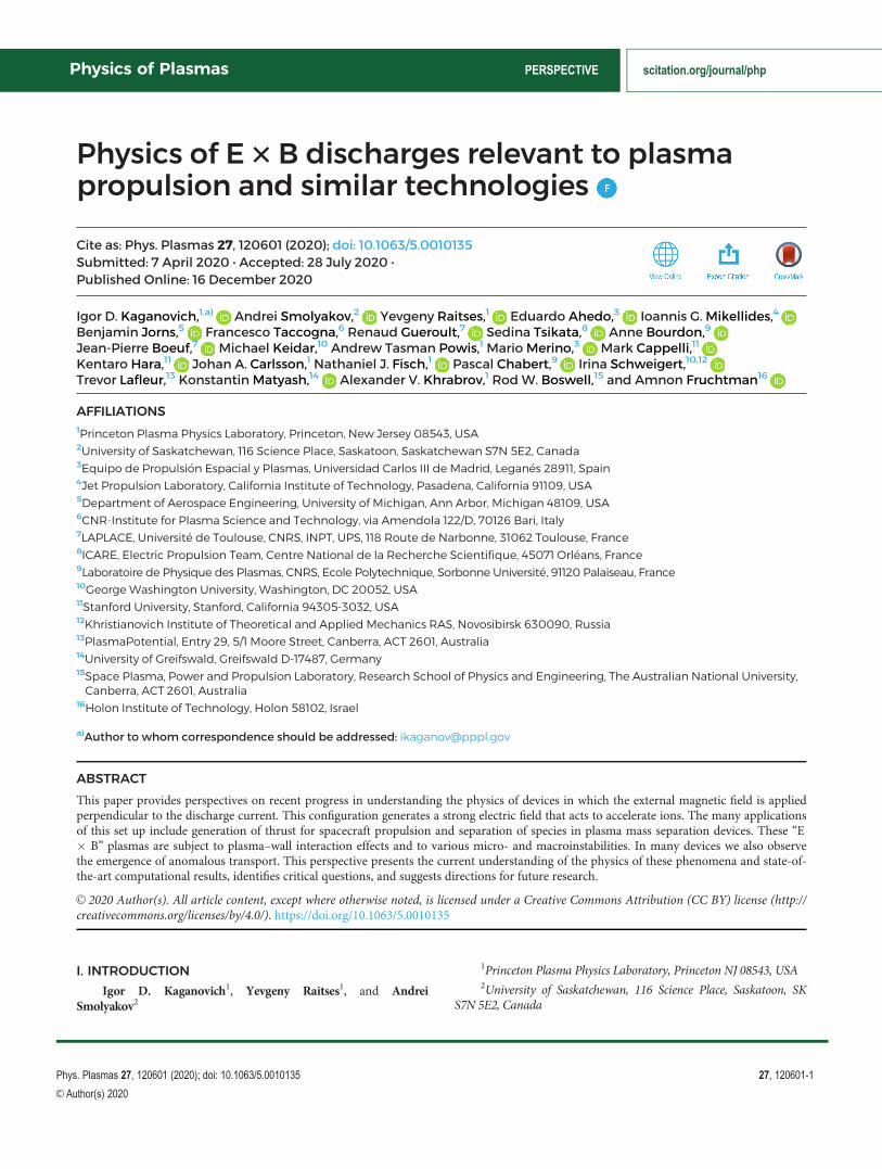
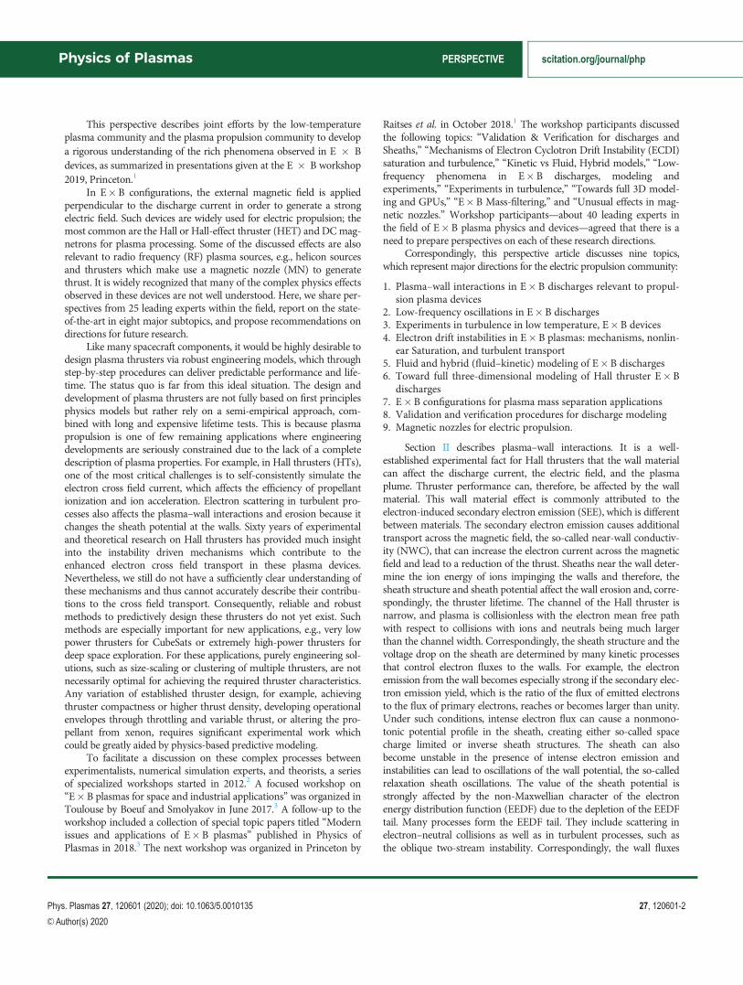
Direct demonstrations of wall material effects on thruster performan-ces6–8 have shown that it can affect strongly the discharge current,both in terms of its magnitude, Fig. 1, and its fluctuation frequency(known as the breathing mode), Fig. 2(a). To a lesser extent, it affectsthrust and thus thrust efficiency (the ratio of the thrust squared to theinput electric power times twice the mass flow rate), Fig. 2(b).
A detailed comparison of plasma properties and discharge opera-tions for Stationary Plasma Thruster (SPT)-type thrusters with boronnitride and carbon segmented walls was performed at PrincetonPlasma Physics laboratory (PPPL), see Ref. 9 and references within.Figure 3 shows the V–I characteristics, the maximum electron temper-ature, and the maximum electric field measured for the boron nitrideceramic channel and the channel with the nonemitting carbon–velvetwalls; a big effect of wall material on these properties is evident for
FIG. 1. Discharge current vs the discharge voltage for two channels made frommachinable glass (GC) and boron nitride (BN) ceramics, respectively, with thesame channel length, L¼ 40 mm, and for two mass flow rates, 1.2 mg/s and1.7 mg/s, from Ref. 6. Reproduced with permission from Raitses et al., in 25thInternational Conference on Electric Propulsion, IEPC 97-056, Cleveland, OH(Electric Rocket Propulsion Society, Cleveland, OH, 1997). Copyright 1997International Conference on Electric Propulsion.
FIG. 2. Experimental study of SPT100-ML discharge as a function of the applied voltage. (a) Frequency of the breathing mode extracted from the experimental frequency spec-tra as a function of discharge voltage, from Ref. 8. Reproduced with permission from Barral et al., Phys. Plasmas 10, 4137 (2003). Copyright 2003 AIP Publishing. (b)Discharge efficiency as a function of voltage for the xenon flow rate 5 mg/s and the coil current 4.5 A, from Ref. 7. Reproduced with permission from Gascon et al., Phys.Plasmas 10, 4123 (2003). Copyright 2003 AIP Publishing.
Physics of Plasmas PERSPECTIVE scitation.org/journal/php
Phys. Plasmas 27, 120601 (2020); doi: 10.1063/5.0010135 27, 120601-5
VC Author(s) 2020
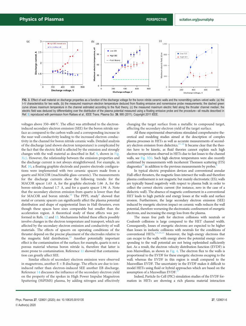
voltages above 350–400V. The effect was attributed to the electron-induced secondary electron emission (SEE) for the boron nitride sur-face as compared to the carbon walls and a corresponding increase inthe near-wall conductivity leading to the increased electron conduc-tivity in the channel for boron nitride ceramic walls. Detailed analysisof the discharge (and shown electron temperature) is complicated bythe fact that the electric field is affected by the emission and stronglychanges with the wall material as described in Ref. 9, shown in Fig.3(c). However, the relationship between the emission properties andthe discharge current is not always straightforward. For example, inRef. 10, a floating graphite electrode and passive electrode configura-tions were implemented with two ceramic spacers made from aquartz and MACOR (machinable glass–ceramic). The measurementsfor the discharge currents show the following trends: for theMACOR spacer 1.63 A, for the graphite electrode 1.66 A, for theboron–nitride channel 1.7 A, and for a quartz spacer 1.94 A. Notethat the secondary electron emission from quartz is lower than thatfor MACOR and boron nitride.10 The PPPL study9 showed thatmetal or ceramic spacers can significantly affect the plasma potentialdistribution and shape of equipotential lines in Hall thrusters, eventhough these spaces have sizes comparable but smaller than theacceleration region. A theoretical study of these effects was per-formed in Refs. 12 and 13. Mechanisms behind these effects possiblyinvolve changes in the electron temperature and transport, which areaffected by the secondary electron emission and conductivity of wallmaterials. The effects of spacers on operating conditions of thethruster depend on the precise placement of the electrodes relative tothe magnetic field distribution.10 Another potentially importanteffect is the contamination of the surface; for example, quartz is not aporous material whereas boron nitride is, therefore that latter ismore prone to contamination. Reference 11 showed that contamina-tion can greatly affect SEE.
Similar effects of secondary electron emission were observedin magnetrons, another E�B discharge. The effects are due to ion-induced rather than electron-induced SEE another EB discharge.Reference 14 discusses the influence of the secondary electron yieldon the property of the spokes in High Power Impulse MagnetronSputtering (HiPIMS) plasma, by adding nitrogen and effectively
changing the target surface from a metallic to compound target,affecting the secondary electron yield of the target surface.
All these experimental observations stimulated comprehensive the-oretical and modeling studies aimed at the description of complexplasma processes in HETs as well as accurate measurements of second-ary electron emission from dielectrics.15–18 It became clear that the theo-ries have to be kinetic, as fluid theories cannot explain such highelectron temperatures observed in HETs due to fast losses to the channelwalls, see Fig. 3(b). Such high electron temperatures were also recentlyconfirmed by measurements with incoherent Thomson scattering (ITS)diagnostics19 in addition to the previous measurements by probes.9
In typical electric propulsion devices and conventional annularHall-effect thrusters, the magnetic lines intersect the walls and thereforeplasma confinement is not magnetic but mainly electrostatic (ES); wallsare typically biased negatively with respect to plasma bulk in order tocollect the correct electric current (for instance, zero in the case of adielectric wall). The absence of magnetic confinement in a conventionalHET leads to high particle and energy losses at the walls and surfaceerosion. Furthermore, the large secondary electron emission (SEE)induced by energetic electron impact on ceramic walls reduces the wallpotential, therefore worsening the electrostatic confinement of energeticelectrons, and increasing the energy loss from the plasma.
The mean free path for electron collisions with neutrals orCoulomb collisions is large compared to the HET channel width.Consequently, losses of energetic electrons are expected to be higherthan losses in inelastic collisions with neutrals for the conditions ofconventional HETs.8,9,20,23 Moreover, the high-energy electrons thatcan escape to the walls with energy above the potential energy corre-sponding to the wall potential are not being replenished sufficientlyfast. As a result, the electron velocity distribution function (EVDF) isnon-Maxwellian, as shown in Fig. 4. The electron flux to the walls isproportional to the EVDF for these energetic electrons escaping to thewall; whereas the EVDF in this region is small compared to theMaxwellian EVDF. The uncertainty in the EVDF makes it difficult tomodel HETs using fluid or hybrid approaches which are based on theassumption of a Maxwellian EVDF.21
Indeed, Particle-In-Cell (PIC) simulation studies of the EVDF for-mation in HETs are showing a rich plasma material interaction
FIG. 3. Effect of wall material on discharge properties as a function of the discharge voltage for the boron nitride ceramic walls and the nonemitting carbon–velvet walls: (a) theI–V characteristics for two walls, (b) the measured maximum electron temperature deduced from floating emissive and nonemissive probe measurements; the dashed greencurve shows maximum temperature in the channel estimated according to the fluid theory, (c) the measured maximum electric field along the thruster channel median; theelectric field was deduced by differentiating over the distribution of the plasma potential measured using a floating emissive probe and the procedure—all results described inRef. 9; reproduced with permission from Raitses et al., IEEE Trans. Plasma Sci. 39, 995 (2011). Copyright 2011 IEEE.
Physics of Plasmas PERSPECTIVE scitation.org/journal/php
Phys. Plasmas 27, 120601 (2020); doi: 10.1063/5.0010135 27, 120601-6
VC Author(s) 2020

phenomena that is non-amenable to simple scaling laws of wide use.These studies include all necessary effects in self-consistent treatment:collisional replenishment of the EVDF for energetic electrons, the influ-ence of the SEE, and the Debye sheath formation. By contrast, scalinglaws were derived for sheath potential and near-wall conductivity for acase of a magnetic field perpendicular to the wall.23
It was also shown using PIC simulations that the averageenergy (or effective temperature) of the electrons decays in thesheath due to the non-Maxwellian distribution functions men-tioned above. Therefore, the usual isothermal sheath theories usedto evaluate the sheath potential drop and the secondary emissionyield are not correct.24,25 A polytropic sheath model has been pro-posed to overcome the limitation of isothermal models. The modelworks well but is not self-consistent and uses the PIC data to evalu-ate the polytropic index.
Two-stream instabilities of the SEE beams injected into the plasmacan reduce the energy of the SEE due to exchange with colder bulk elec-trons and increase the number of energetic SEE electrons trapped by apotential well and therefore make the total EVDF closer to aMaxwellian.27 The evolution of SEE within the plasma needs to take intoaccount possible re-collection by the walls.26,28 Asymmetries in theEVDF caused by cylindrical effects can be significant too.29,64 The sheathstructure and plasma–wall interaction processes are quite sensitive to thedetailed description of SEE features (e.g., to the amount of true-secondary vs elastically or inelastically backscattered electrons).27,30
At SEE yields of about 100%, the sheath becomes space-chargelimited, and in this regime, the sheath may become unstable.31–34
Furthermore, in the center of the acceleration region of a HET, theaxial electric field is maximum and the resulting E�B drifts can be onthe order of the electron thermal velocity, thus enhancing the impact
energy of electrons and the transition to a space-charge limited unsta-ble sheath.30
The sheath instability (in the radial direction) may work as a trig-ger for the azimuthal fluctuations. An example of the temporal
FIG. 4. (a) Electron velocity distribution functions at the thruster cylindrical channel midradius M, of (black) primary electrons, (blue) secondary electrons from the channel innerwall W1, and (red) secondary electrons from the channel outer wall W2, showing depleted tails; vertical lines mark the wall potential value, from Ref. 26; reproduced with per-mission from Dom�ınguez-V�azquez et al., Plasma Sources Sci. Technol. 27, 064006 (2018). Copyright 2018 IOP Publishing. (b) EVDF over vx and vz shown as a 3D plot andas a 2D plot with contour lines; the plasma potential relative to the wall is 20 V, the x-axis is normal to the wall and the z-axis is parallel to the walls, from Ref. 22; reproducedwith permission from Sydorenko et al., Phys. Plasmas 13, 014501 (2006). Copyright 2006 AIP Publishing.
FIG. 5. Temporal evolution of current–voltage (I–V) characteristics at the outer wallof a HET. From Ref. 35; reproduced with permission from Taccogna et al., Appl.Phys. Lett. 94, 251502 (2009). Copyright 2009 AIP Publishing.
Physics of Plasmas PERSPECTIVE scitation.org/journal/php
Phys. Plasmas 27, 120601 (2020); doi: 10.1063/5.0010135 27, 120601-7
VC Author(s) 2020
evolution of the total current collected on the outer wall and the corre-sponding floating potential is shown in Fig. 5. It should be pointed outthat in this case the instability is detected only on the outer wall, wherethe secondary electron emission coefficient reaches a value larger than1.
In the case of high SEE yield, the transition was observed from aspace-charge limited sheath to an inverse sheath.36 The important dif-ference between the two regimes is that ions are not accelerated towardthe wall in the inverse sheath case and thus improve ion confinement(but deteriorate energy losses). This phenomenon has been studied inthe context of large thermionic emission, mainly related to emissiveprobes and arcs.37–39 Excitation of ion–acoustic waves in the presenceof a very intense SEE when an inverse sheath forms was observed inthe HET channel for a high electric field.43
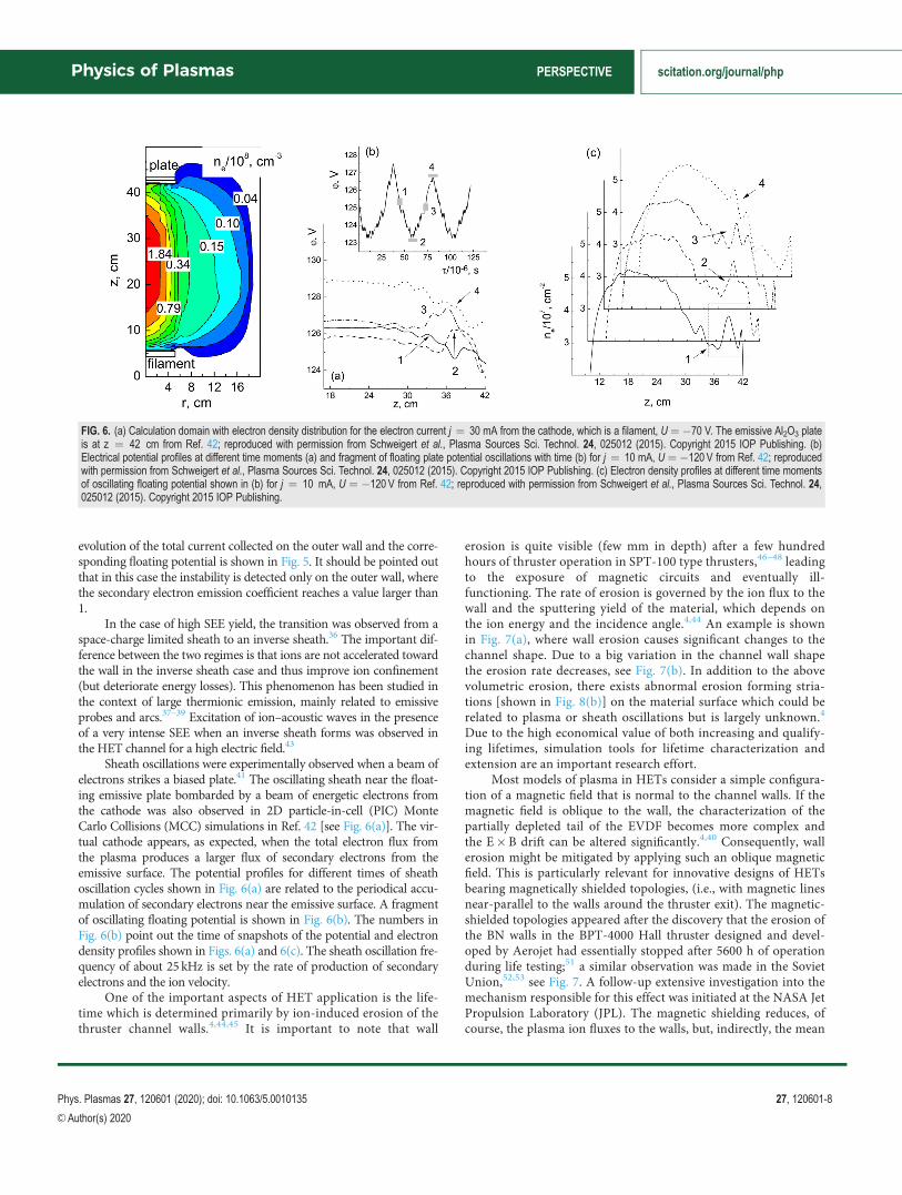
Sheath oscillations were experimentally observed when a beam ofelectrons strikes a biased plate.41 The oscillating sheath near the float-ing emissive plate bombarded by a beam of energetic electrons fromthe cathode was also observed in 2D particle-in-cell (PIC) MonteCarlo Collisions (MCC) simulations in Ref. 42 [see Fig. 6(a)]. The vir-tual cathode appears, as expected, when the total electron flux fromthe plasma produces a larger flux of secondary electrons from theemissive surface. The potential profiles for different times of sheathoscillation cycles shown in Fig. 6(a) are related to the periodical accu-mulation of secondary electrons near the emissive surface. A fragmentof oscillating floating potential is shown in Fig. 6(b). The numbers inFig. 6(b) point out the time of snapshots of the potential and electrondensity profiles shown in Figs. 6(a) and 6(c). The sheath oscillation fre-quency of about 25 kHz is set by the rate of production of secondaryelectrons and the ion velocity.
One of the important aspects of HET application is the life-time which is determined primarily by ion-induced erosion of thethruster channel walls.4,44,45 It is important to note that wall
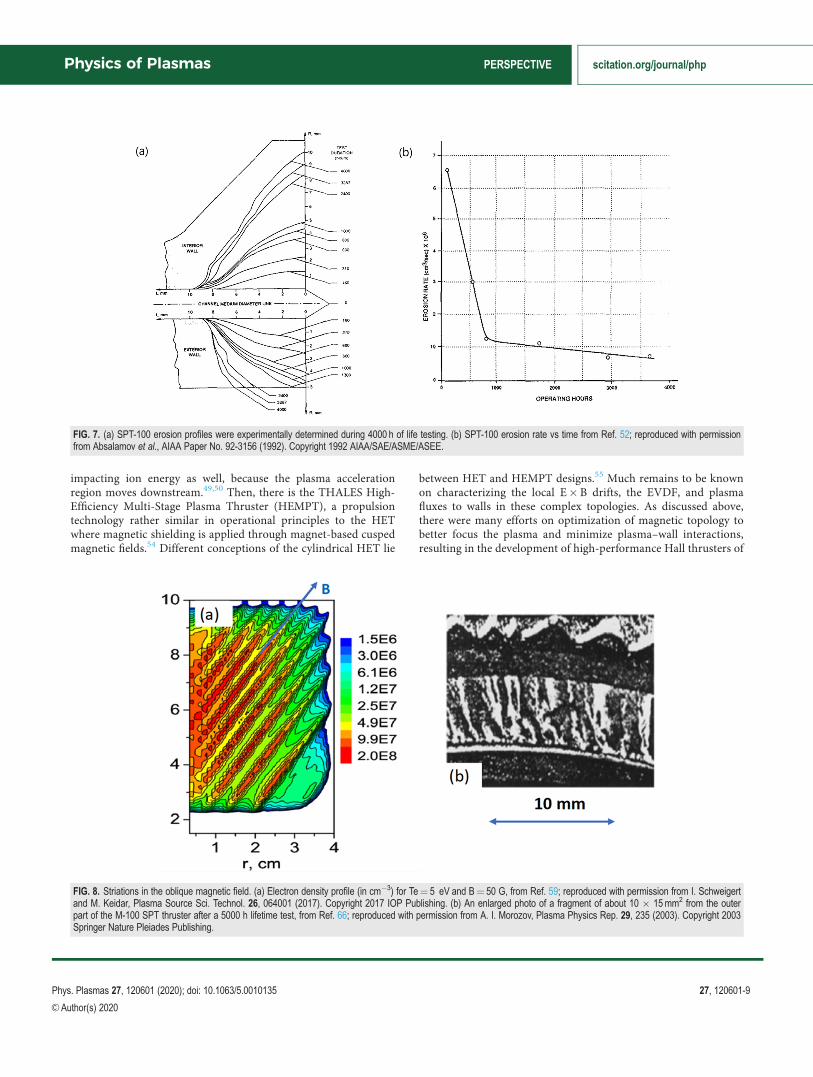
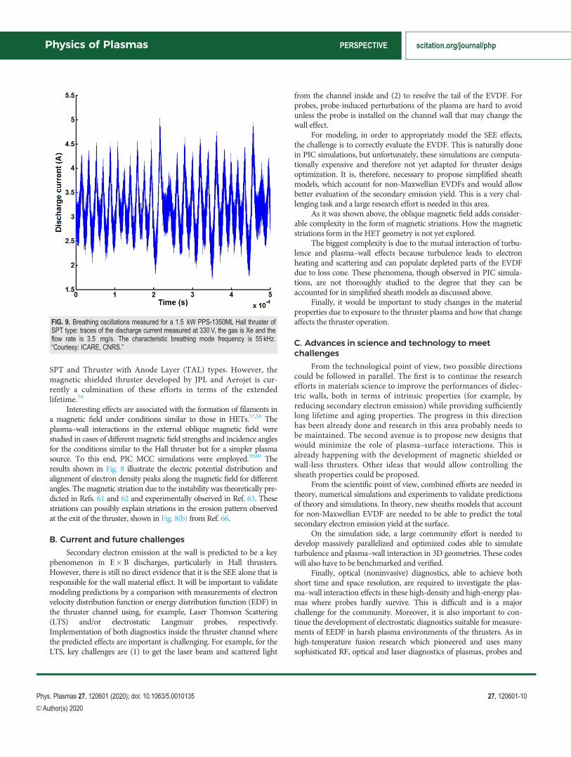
erosion is quite visible (few mm in depth) after a few hundredhours of thruster operation in SPT-100 type thrusters,46–48 leadingto the exposure of magnetic circuits and eventually ill-functioning. The rate of erosion is governed by the ion flux to thewall and the sputtering yield of the material, which depends onthe ion energy and the incidence angle.4,44 An example is shownin Fig. 7(a), where wall erosion causes significant changes to thechannel shape. Due to a big variation in the channel wall shapethe erosion rate decreases, see Fig. 7(b). In addition to the abovevolumetric erosion, there exists abnormal erosion forming stria-tions [shown in Fig. 8(b)] on the material surface which could berelated to plasma or sheath oscillations but is largely unknown.4
Due to the high economical value of both increasing and qualify-ing lifetimes, simulation tools for lifetime characterization andextension are an important research effort.
Most models of plasma in HETs consider a simple configura-tion of a magnetic field that is normal to the channel walls. If themagnetic field is oblique to the wall, the characterization of thepartially depleted tail of the EVDF becomes more complex andthe E�B drift can be altered significantly.4,40 Consequently, wallerosion might be mitigated by applying such an oblique magneticfield. This is particularly relevant for innovative designs of HETsbearing magnetically shielded topologies, (i.e., with magnetic linesnear-parallel to the walls around the thruster exit). The magnetic-shielded topologies appeared after the discovery that the erosion ofthe BN walls in the BPT-4000 Hall thruster designed and devel-oped by Aerojet had essentially stopped after 5600 h of operationduring life testing;51 a similar observation was made in the SovietUnion,52,53 see Fig. 7. A follow-up extensive investigation into themechanism responsible for this effect was initiated at the NASA JetPropulsion Laboratory (JPL). The magnetic shielding reduces, ofcourse, the plasma ion fluxes to the walls, but, indirectly, the mean
FIG. 6. (a) Calculation domain with electron density distribution for the electron current j ¼ 30 mA from the cathode, which is a filament, U ¼ �70 V. The emissive Al2O3 plateis at z ¼ 42 cm from Ref. 42; reproduced with permission from Schweigert et al., Plasma Sources Sci. Technol. 24, 025012 (2015). Copyright 2015 IOP Publishing. (b)Electrical potential profiles at different time moments (a) and fragment of floating plate potential oscillations with time (b) for j ¼ 10 mA, U ¼ �120 V from Ref. 42; reproducedwith permission from Schweigert et al., Plasma Sources Sci. Technol. 24, 025012 (2015). Copyright 2015 IOP Publishing. (c) Electron density profiles at different time momentsof oscillating floating potential shown in (b) for j ¼ 10 mA, U ¼ �120 V from Ref. 42; reproduced with permission from Schweigert et al., Plasma Sources Sci. Technol. 24,025012 (2015). Copyright 2015 IOP Publishing.
Physics of Plasmas PERSPECTIVE scitation.org/journal/php
Phys. Plasmas 27, 120601 (2020); doi: 10.1063/5.0010135 27, 120601-8
VC Author(s) 2020
impacting ion energy as well, because the plasma accelerationregion moves downstream.49,50 Then, there is the THALES High-Efficiency Multi-Stage Plasma Thruster (HEMPT), a propulsiontechnology rather similar in operational principles to the HETwhere magnetic shielding is applied through magnet-based cuspedmagnetic fields.54 Different conceptions of the cylindrical HET lie
between HET and HEMPT designs.55 Much remains to be knownon characterizing the local E�B drifts, the EVDF, and plasmafluxes to walls in these complex topologies. As discussed above,there were many efforts on optimization of magnetic topology tobetter focus the plasma and minimize plasma–wall interactions,resulting in the development of high-performance Hall thrusters of
FIG. 7. (a) SPT-100 erosion profiles were experimentally determined during 4000 h of life testing. (b) SPT-100 erosion rate vs time from Ref. 52; reproduced with permissionfrom Absalamov et al., AIAA Paper No. 92-3156 (1992). Copyright 1992 AIAA/SAE/ASME/ASEE.
FIG. 8. Striations in the oblique magnetic field. (a) Electron density profile (in cm�3) for Te¼ 5 eV and B¼ 50 G, from Ref. 59; reproduced with permission from I. Schweigertand M. Keidar, Plasma Source Sci. Technol. 26, 064001 (2017). Copyright 2017 IOP Publishing. (b) An enlarged photo of a fragment of about 10 � 15mm2 from the outerpart of the M-100 SPT thruster after a 5000 h lifetime test, from Ref. 66; reproduced with permission from A. I. Morozov, Plasma Physics Rep. 29, 235 (2003). Copyright 2003Springer Nature Pleiades Publishing.
Physics of Plasmas PERSPECTIVE scitation.org/journal/php
Phys. Plasmas 27, 120601 (2020); doi: 10.1063/5.0010135 27, 120601-9
VC Author(s) 2020
SPT and Thruster with Anode Layer (TAL) types. However, themagnetic shielded thruster developed by JPL and Aerojet is cur-rently a culmination of these efforts in terms of the extendedlifetime.56
Interesting effects are associated with the formation of filaments ina magnetic field under conditions similar to those in HETs.57,58 Theplasma–wall interactions in the external oblique magnetic field werestudied in cases of different magnetic field strengths and incidence anglesfor the conditions similar to the Hall thruster but for a simpler plasmasource. To this end, PIC MCC simulations were employed.59,60 Theresults shown in Fig. 8 illustrate the electric potential distribution andalignment of electron density peaks along the magnetic field for differentangles. The magnetic striation due to the instability was theoretically pre-dicted in Refs. 61 and 62 and experimentally observed in Ref. 63. Thesestriations can possibly explain striations in the erosion pattern observedat the exit of the thruster, shown in Fig. 8(b) from Ref. 66.
B. Current and future challenges
Secondary electron emission at the wall is predicted to be a keyphenomenon in E�B discharges, particularly in Hall thrusters.However, there is still no direct evidence that it is the SEE alone that isresponsible for the wall material effect. It will be important to validatemodeling predictions by a comparison with measurements of electronvelocity distribution function or energy distribution function (EDF) inthe thruster channel using, for example, Laser Thomson Scattering(LTS) and/or electrostatic Langmuir probes, respectively.Implementation of both diagnostics inside the thruster channel wherethe predicted effects are important is challenging. For example, for theLTS, key challenges are (1) to get the laser beam and scattered light
from the channel inside and (2) to resolve the tail of the EVDF. Forprobes, probe-induced perturbations of the plasma are hard to avoidunless the probe is installed on the channel wall that may change thewall effect.
For modeling, in order to appropriately model the SEE effects,the challenge is to correctly evaluate the EVDF. This is naturally donein PIC simulations, but unfortunately, these simulations are computa-tionally expensive and therefore not yet adapted for thruster designoptimization. It is, therefore, necessary to propose simplified sheathmodels, which account for non-Maxwellian EVDFs and would allowbetter evaluation of the secondary emission yield. This is a very chal-lenging task and a large research effort is needed in this area.
As it was shown above, the oblique magnetic field adds consider-able complexity in the form of magnetic striations. How the magneticstriations form in the HET geometry is not yet explored.
The biggest complexity is due to the mutual interaction of turbu-lence and plasma–wall effects because turbulence leads to electronheating and scattering and can populate depleted parts of the EVDFdue to loss cone. These phenomena, though observed in PIC simula-tions, are not thoroughly studied to the degree that they can beaccounted for in simplified sheath models as discussed above.
Finally, it would be important to study changes in the materialproperties due to exposure to the thruster plasma and how that changeaffects the thruster operation.
C. Advances in science and technology to meetchallenges
From the technological point of view, two possible directionscould be followed in parallel. The first is to continue the researchefforts in materials science to improve the performances of dielec-tric walls, both in terms of intrinsic properties (for example, byreducing secondary electron emission) while providing sufficientlylong lifetime and aging properties. The progress in this directionhas been already done and research in this area probably needs tobe maintained. The second avenue is to propose new designs thatwould minimize the role of plasma–surface interactions. This isalready happening with the development of magnetic shielded orwall-less thrusters. Other ideas that would allow controlling thesheath properties could be proposed.
From the scientific point of view, combined efforts are needed intheory, numerical simulations and experiments to validate predictionsof theory and simulations. In theory, new sheaths models that accountfor non-Maxwellian EVDF are needed to be able to predict the totalsecondary electron emission yield at the surface.
On the simulation side, a large community effort is needed todevelop massively parallelized and optimized codes able to simulateturbulence and plasma–wall interaction in 3D geometries. These codeswill also have to be benchmarked and verified.
Finally, optical (noninvasive) diagnostics, able to achieve bothshort time and space resolution, are required to investigate the plas-ma–wall interaction effects in these high-density and high-energy plas-mas where probes hardly survive. This is difficult and is a majorchallenge for the community. Moreover, it is also important to con-tinue the development of electrostatic diagnostics suitable for measure-ments of EEDF in harsh plasma environments of the thrusters. As inhigh-temperature fusion research which pioneered and uses manysophisticated RF, optical and laser diagnostics of plasmas, probes and
FIG. 9. Breathing oscillations measured for a 1.5 kW PPS-1350ML Hall thruster ofSPT type: traces of the discharge current measured at 330 V, the gas is Xe and theflow rate is 3.5 mg/s. The characteristic breathing mode frequency is 55 kHz.“Courtesy: ICARE, CNRS.”
Physics of Plasmas PERSPECTIVE scitation.org/journal/php
Phys. Plasmas 27, 120601 (2020); doi: 10.1063/5.0010135 27, 120601-10
VC Author(s) 2020

energy analyzers remain important diagnostics for edge physics andespecially so at the divertors of fusion reactors.
D. Conclusions
There was a large progress in understanding plasma–wallinteraction in the recent decade. A future challenge is to generalizethe developed understanding for realistic devices in 3D accountingfor self-consistent interaction of turbulence and plasma–wall inter-actions and provide experimental validation of these effects usingadvanced diagnostics.
III. LOW-FREQUENCY OSCILLATIONS IN E 3 BDISCHARGES
Yevgeny Raitses1, Andrei Smolyakov2, Mark Cappelli3,Kentaro Hara3, Jean-Pierre Boeuf4, and Igor Kaganovich1
1Princeton Plasma Physics Laboratory, Princeton NJ 08543, USA2University of Saskatchewan, 116 Science Place, Saskatoon, SK
S7N 5E2, Canada3Stanford University, Stanford, California 94305-3032, USA4LAPLACE, University of Toulouse, CNRS, INPT, UPS, 118 Route
de Narbonne, 31062 Toulouse, France
A. State-of-the-art and recent progress
Low-frequency (typically <100 kHz) oscillations, includingspokes and breathing modes, are some of the most prominent exam-ples of self-organization in partially magnetized quasineutral plasmasof crossed-field devices at a wide range of pressures �0.1–100 mTorr,such as Hall thrusters, Penning discharges, and sputtering magnet-rons.7,65,67–70 The spoke mode manifests itself as strong perturbationsin plasma density that propagate in the E � B direction perpendicularto the crossed electric (E) and magnetic (B) fields, generating substan-tial components in electric field in this E�B direction.65,67–69 Thebreathing mode propagates in the direction of the external electricfield, and is one of the powerful modes observed in Hall thrusters. Itreveals itself in oscillations of the discharge current [see Figs. 9 and2(a)], often reaching amplitudes comparable to the mean dischargecurrent itself.7,65,71 While these modes have been known and studiedfor some time, only recently have coordinated efforts been madetoward self-consistent modeling,72–77 detailed experimental valida-tion,78–82 and their control.83,86–88
For cylindrical devices, the spokes rotate azimuthally in the direc-tion of the E � B drift, but with a speed that is an order of magnitude
smaller than the E � B drift velocity.67,68,78,80,89–92 The mode numberof these spokes is usually low, m ¼ 1 � 8.67,68,81,93,94 It has beenreported that anomalous (turbulent) electron current may beenhanced in the spoke, carrying 20%–90% of the total discharge cur-rent.91,92 Although the mechanism for spoke formation is still debated,one candidate is the Simon–Hoh (SH)-type instability,95,96 driven bythe combination of the applied electric field and the gradient in plasmadensity. A modified theory of this instability for partially magnetizedcollisionless plasmas was developed74,79,97,98,107 and experimentallyverified for some conditions.67,79,92,93,97
Recent results of large-scale Particle-In-Cell (PIC) simulations ofa Penning discharge75,108 were found to be in good agreement withexperimental data,92 showing the formation of a m¼ 1 spoke rotatingwith a frequency of a few kHz (Fig. 10), generating anomalous currentdue to fluctuations. The scaling of the spoke frequency deduced fromboth the simulations and experiments was consistent with theoreticalpredictions for SH instability in collisionless plasmas,97 i.e.,f /
ffiffiffiffiffiffiffiffiffiffiffiffiffiffiffiffiffiErLn=mi
p, where Er is the radial electric field, Ln is the gradient
density scale, andmi is the ion mass.75 According to these PIC simula-tions, the ionization of the working gas has a minor effect on the spokeformation.
Unfavorable magnetic field gradients can lead to violent pertur-bations, but typical magnetic profiles in modern Hall thrusters, aredesigned to partially stabilize the most disruptive spoke modes.65 Thetheory of collisionless SH instability has been modified to include thegradients of the magnetic field and electron temperature. Withthese modifications it is generally referred to as the gradient-driftinstability.74 Linear analysis109,110 as well as recent particle-fluid hybridsimulations show that gradient-drift effects are critical for the forma-tion of azimuthally rotating spoke-like structures in the typical condi-tions of Hall thrusters.81
Although simulations have shown that spokes can form in colli-sionless plasmas without ionization,75 there is strong evidence fromnumerous experiments in high power pulsed magnetron discharges(High Power Impulse Magnetron Sputtering—HiPIMS discharges)and in lower power, DC magnetron discharges99,100,103 that ionizationcan play an important role in the formation and dynamics of spokes.An important similarity between magnetron and Hall thruster dis-charges is the existence of a region where the radial component of themagnetic field decreases axially toward the anode. Recent experimentsin HiPIMS and DC magnetron discharges have shown that theobserved spokes are associated with an ionization instability rotating
FIG. 10. PIC simulations of electron density contours in a real scale E � B Penning system with diameter 5 cm, showing spoke rotation, at simulation times, from left to right;61.4 ls, 65.8 ls, 70.7 ls, and 74.2 ls.75 Reproduced with the permission from Powis et al., Phys. Plasmas 25, 072110 (2018). Copyright 2018 AIP Publishing.
Physics of Plasmas PERSPECTIVE scitation.org/journal/php
Phys. Plasmas 27, 120601 (2020); doi: 10.1063/5.0010135 27, 120601-11
VC Author(s) 2020

in the azimuthal (E�B) direction. The measurements reveal the exis-tence of a double-layer structure with a large electric field at the lead-ing edge of the ionization zone and this double layer plays a crucialrole in the energization of electrons.103 References 101 and 102 discussthe experimentally determined potential structures of spokes inHiPIMS. The presence of a double layer and enhanced ionization atthe spoke front is reminiscent of the critical ionization velocity modelof Ref. 105 and of the PIC simulations of Ref. 63 and 106 although thevelocity of the spoke measured in HiPIMS and magnetron dischargesdoes not necessarily match the theoretical critical ionization velocity.Moreover experiments,79,99,100,103 and recent modeling104 have evi-denced that spokes can rotate in the �E�B direction (at low power)as well as in theþE�B direction (at higher power).
The very detailed and recently published measurements of thespoke properties in HiPIMS and DC magnetron discharges shouldopen the way for a better understanding of these structures and oftheir dynamics based on modeling and simulations. Although thephysics of HiPIMS is more complex (e.g., ionization of the sputteredatoms), it seems very likely that spokes in Hall thruster and magnetrondischarges share several common properties.
Ionization plays a key role in the axial (breathing) mode oscilla-tions.70,81,82,111–113 Experiments demonstrated the dependence of theseoscillations on the thruster operating conditions such as dischargevoltage, magnetic field strength and topology, gas flow, cathode opera-tion, and background pressure.7,81,82,86 A zero-dimensional predator–-prey model for the coupled evolution of the ion and neutral density112
predicts the oscillations, however, the equivalent one-dimensionalmodel shows no oscillations. It was also realized that self-consistentelectron dynamics is important.69,113 The resistive instability114,115 dueto the phase shift in the response of the electron current (resistive) andion current (inertial) to the perturbation of the electric field was pro-posed to be a triggering element of the breathing mode.81,116,117
Besides, the electron temperature evolution was also shown to beimportant and needs to be included into fluid or hybrid models.69,81,114
Recent studies that include fluctuations of the electron temperaturehave shown that temperature may render zero-dimensional preda-tor–prey models unstable.81 Without the variation of the electron tem-perature and ionization rate taken into account, the one-dimensionalmodeling shows no excitation of the breathing oscillations.117,118
B. Current and future challenges
There is a growing realization that in conditions relevant to thepractical operation of E�B plasma devices, the low-frequency azi-muthal and axial modes result from a complex interplay of variousphenomena. An understanding of these complex interactions remainsfar from complete and they present a critical challenge for the develop-ment of predictive modeling tools needed for existing and future appli-cations. For stronger magnetic fields and faster ion and electronrotations, it is important to investigate the onset of a Simon–Hohinstability taking into account centrifugal forces119,120 that are espe-cially relevant to novel mass separation devices discussed in Sec. VII.
As for experiments, it is challenging to independently control thedischarge parameters such as local electric field and density gra-dients—the properties important to the instability. This couplingmakes it difficult to identify the cause for the ubiquitous presence oflarge-scale azimuthal disturbances while the smaller scale azimuthal
modes typically have larger growth rates: for the low-m modes themode growth rate increases almost linearly with the wavenumber.67,97
Fluid simulations have shown that the low-mmodes can be formed asa result of nonlinear inverse energy cascade from small-scalemodes.74,107 Furthermore, magnetic field, temperature, and plasmagradients, which are present in many engineering devices (e.g., Hallthrusters and magnetrons),65,77,121 and the presence of physicalboundaries and associated sheaths92 all need to be taken intoaccount.122 Combined effects of gradients, nonlocal electron kinetics,and the coupling between large and small-scale plasma structures(energy cascade) should continue to be explored theoretically, numeri-cally and experimentally. It is also important to further explore theeffects of ionization and neutral depletion in such complex, highlynonuniform plasma systems.123–125
Theoretical models and simulations of the breathing mode sug-gest a large sensitivity to the values of the effective electron mobilityalong the applied electric field or even wall material as was shown inFig. 2(a). Empirical values of the anomalous mobility are typicallyused for modeling of the breathing oscillations with values adjusted toachieve reasonable agreement with experiments.121 In addition toanomalous mobility, the models should include other anomaloustransport coefficients, including anomalous heating and energy losses.For the most part, physical mechanisms governing these anomalouseffects are not well-understood. For example, it is unknown whetherthe anomalous heating can be described by the same effective collisionfrequency as the anomalous electron mobility. Understanding theseanomalous effects is required for further progress in this research field.
With a few exceptions, modeling of the breathing and azimuthalspoke modes has been performed separately and without consideringpossible coupling effects. Some experimental data suggest that there isa coupling between them.126 A coupling between the two modes isexpected because the azimuthal mode is driven by axial gradients inplasma parameters such as the density and electric field, which experi-ence large spatial and temporal variations during breathing modeoscillations. Control of the axial oscillations modifies the driving forcesfor the azimuthal modes.127 Recent control experiments have usedvarying cathode electron emission86 as well as external voltage modu-lation,127 demonstrating a suppression of the oscillations associatedwith both of these modes.
C. Advances in science and technology to meet thesechallenges
Modern computational tools to study E�B plasma devicesinclude fluid, hybrid (PIC for ions and atoms and fluid for electrons),and full PIC (PIC for all plasma species) simulation codes.Benchmarking should be performed for simulations with identical con-ditions, specifically relevant to low-frequency phenomena. Codes shouldbe benchmarked against each other to better understand the limitationsof numerical algorithms and physics approximations. For instance, afluid model with electron pressure closure111 has been proposed to elim-inate the numerical uncertainties in conventional quasineutral models.Alternative approaches such as continuum grid-based kinetic models,or direct kinetic simulations,128,129 can be used to understand the issueof numerical noise in PIC codes. PIC codes can be used to verify thenumerical diffusion issue in direct kinetic simulations.
Crucial for validating simulation results are experiments capableof measuring plasma properties with spatial and temporal resolution,
Physics of Plasmas PERSPECTIVE scitation.org/journal/php
Phys. Plasmas 27, 120601 (2020); doi: 10.1063/5.0010135 27, 120601-12
VC Author(s) 2020

including energy distribution functions (EDFs) of the electron, ion,and neutral species in different directions along with the electric andmagnetic fields in the E�B direction, and time-resolved (<10�4 s)electric field measurements. Experiments involving active control oflow-frequency oscillations86,87,111 are also important as they mayreveal underlying physical mechanisms of instabilities needed to becaptured by truly predictive models.
The use of fast-sweeping electrostatic probes and energy analyzersfor measurements of electron and ion EDFs, and plasma potential isappropriate when these invasive diagnostics induce minor plasma per-turbations (e.g., Penning systems). However, for Hall thrusters and mag-netron discharges, with nonuniformmagnetic fields and strong potentialgradients, nonintrusive diagnostics, such as Laser-Induced Fluorescence(LIF) of electronically excited ions and atoms130–135 and Laser ThomsonScattering (LTS),136 may be more quantitative in measuring speciesEDFs in these devices. A critical challenge for time-resolving LIF of theion EDF is accounting for electronically excited states produced duringspoke and breathing oscillations by direct ionization of neutral atoms aswell as ions in other electronically excited states.137,138 For measurementsof the electron EDF using LTS, a key challenge is a relatively low electrondensity detection limit of 1010 cm�3, making it difficult to characterizethe EDF high energy tail that may develop and be affected in low fre-quency spoke and breathing mode cycles.
D. Conclusions
Low-frequency oscillations occurring in E�B discharges are themost powerful oscillations and therefore, may significantly affect theperformance of these devices in several different ways including but notlimited to power losses on electron transport and heating, defocusingof ions, and mismatch between the device and the power supply.Therefore, it is important to understand these oscillations and theircontrol. The progress made in understanding the low-frequency phe-nomena, including spoke and breathing oscillations, has been driven by
combined efforts of modern experimentation, theory, and simulationstudies. However, there is an emerging need for dedicated efforts tocompare and benchmark various numerical codes. Experiments capa-ble of measuring spatially and temporally resolved plasma propertiesduring low-frequency oscillations will be crucial to advance our under-standing of these phenomena. Continued advances in computationalcapabilities will eventually allow simulations to be carried out at scaleand over the times needed to resolve these low-frequency structures.The ultimate challenge and the long-term goal would be the develop-ment of experimentally validated predictive computational tools thatself-consistently model anomalous electron mobility and heat conduc-tion, because these transport phenomena play a critical role in low-frequency oscillations as observed during nominal operation of E�Bplasma devices. Then, the next step would require the implementationof modeling including electric circuits with passive and active controlof these oscillations and other means of their control such as segmentedelectrodes,83 cathode gas flow,84,85 and electron emission.90
IV. EXPERIMENTS IN TURBULENCE IN LOWTEMPERATURE, E�B DEVICES
Benjamin Jorns1 and Sedina Tsikata21Department of Aerospace Engineering, University of Michigan,
Ann Arbor, MI, USA2ICARE, Electric Propulsion Team, Centre National de la
Recherche Scientifique, Orl�eans, France
A. State-of-the-art and recent progress
While there are many types of plasma oscillations in low-temperature, E�B devices, including the longer-wavelength modeslinked to plasma inhomogeneities and ionization (see Secs. III andVI),70,140 there is a growing interest in experimentally characterizingthe role of short wavelength (<1mm) plasma turbulence in these devi-ces. This interest largely has been motivated by numerical studies(starting with the work of Ref. 142 and more recently, in work such as
FIG. 11. (a) Schematic for Hall thruster showing measurement location for the coherent Thomson scattering system relative to the Hall thruster; the measurement location ofthe data of (b) and (c) was 7.5 mm. The diagnostic allows variation of the magnitude of the observation wave vector k and also its orientation, for example, via rotation throughan angle a in the (E � B, E) plane, as illustrated. (b) Dispersion relationship for the electron cyclotron drift instability in the E� B drift direction measured using CTS. The cor-responding group velocity is 3.3 km/s. Adapted from Ref. 143. Reproduced with the permission from Tsikata et al., Phys. Plasmas 16, 033506 (2009). Copyright 2009 AIPPublishing. (c) Energy scaling with wavenumber for the ECDI, determined using CTS. Figure shows the log of the calibrated density fluctuation amplitude [known as thedynamic form factor S(k,x)] as a function of frequency and wavenumber.
Physics of Plasmas PERSPECTIVE scitation.org/journal/php
Phys. Plasmas 27, 120601 (2020); doi: 10.1063/5.0010135 27, 120601-13
VC Author(s) 2020
Ref. 141 and references therein) that have shown these oscillationsmay be a dominant driver of anomalous electron transport in low-temperature E�B systems. To this end, experiments have investi-gated which waves are present in these devices, how much energyis contained in these waves, and how these measured wave proper-ties can be related to anomalous transport. These experimentalstudies have been facilitated by the development of new diagnostictechniques in the past fifteen years—such as coherent Thomsonscattering (CTS), developed in response to numerical work ofRef. 142—that have allowed for unprecedented levels of noninva-sive access and resolution.
Most experimental efforts on turbulent measurements to datehave focused on fluctuations formed in the E�B direction (althoughother short wavelength fluctuations—the axially directed two-streaminstability— have been detected and characterized as well139). Forexample, Fig. 11 shows a set of representative experimental results fora Hall thruster discharge. In these experiments, which are described inRefs. 143 and 147, CTS was employed to interrogate the short-wavelength oscillations in the electron density in the direction of theHall drift. Figure 11(a) illustrates the geometry of the system and themeasurement location, downstream of the thruster exit, with investiga-tions performed at an observation wave vector k with variable orienta-tion in the (E�B, E) plane. Figure 11(b) shows the resultingmeasured wave dispersion from CTS in the Hall (azimuthal) direction.It was proposed in Refs. 143 and 147 that the features of the measureddispersion—specifically, of MHz, mm-scale density fluctuations in theazimuthal direction—were indicative of the presence of the electroncyclotron drift instability (ECDI). The characteristic physics of theECDI (also referred to more generally as the electron drift instability,or EDI) are discussed in more detail in Sec. V.
To further support the link between experiment and ECDI, Refs.143 and 147 drew parallels between their measurements and previous2D numerical and linear kinetic theory studies142,154,182 that had pre-dicted that the ECDI would propagate in the Hall thruster plasma.Subsequent measurements on other Hall thruster configurations usingdifferent probing techniques144 as well as studies on a similar E�Bdevice, the planar magnetron operating in the pulsed, high-current,high-density regime known as HiPIMS155 also have shown dispersionswhich the authors have attributed to the presence of ECDI. The grow-ing evidence that the ECDI exists in these devices is physically impact-ful as this mode was the first one linked (in simulations142) toturbulence-driven anomalous cross field transport.
With that said, as discussed in more detail in Sec. V, there issome debate in the community about the appropriateness of labelingthe measured waves as so-called ECDI/EDI. This stems from the factthat the linear dispersion in Fig. 11(b) exhibits features that could alsobe described simply as ion sound (group velocities in the Hall directioncommensurate with the local ion sound speed). This is an intriguingresult as the classical ion sound is unmagnetized and therefore wouldnot be expected to appear in the Hall direction. To reconcile thisapparent incongruity, some theories (Sec. V) posit that when waveamplitudes become sufficiently large for the ECDI, the waves becomeeffectively unmagnetized, leading to ion sound-like behavior.Alternatively, experimental measurements have motivated a differentexplanation. In particular, measurements have shown the existence ofa finite wave component along the magnetic field.157 It subsequentlyhas been demonstrated (Refs. 156 and 158 and in Sec. V) that the
presence of 3D effects like this parallel propagation also may accountfor the sound-like dispersion.
Another question that experiments have tried to address is howmuch energy is contained in the excited waves. This is a critical con-sideration as the anomalous transport depends both on the wave-lengths of the excited modes and the energy in each mode (Sec. V).Early simulation work based on 1D and 2D kinetic theory indicatedthat energy could be concentrated at the electron cyclotron resonancecorresponding to maximum growth (e.g., see Fig. 14 in Sec. V) withlarge amplitudes (exceeding>10% of the thermal background). Thistype of energy concentration is manifested in numerical results as awell-defined, characteristic length scale for the instability (e.g., Fig. 16in Sec. V). The first experimental measurements, in contrast, indicatedthat the shape and amplitude of the power spectrum measured inactual thrusters is significantly different.
Figure 11(c) illustrates this contrast with a plot of the distri-bution of energy over wavelengths from the CTS measurementsperformed on the same device where the dispersion was measuredin Fig. 11(b). This representation shows the energy spectrum scal-ing [using the calibrated density fluctuation amplitude, known asthe dynamic form factor S(k, x)] over the range of wavenumbers kand frequencies x found in experiments in Ref. 143. Such informa-tion has been used to establish scaling laws (see Ref. 143) relatingthe integrated fluctuation intensity S(k) to k. An exponentialdecay with wavenumber has been observed, with an e-decrementon the order of the electron Larmor radius (<1mm), andamplitudes< 1% of the thermal background. The shape of thisspectrum is consistent with a classically turbulent distribution inwhich the growth of the energy of the waves is governed by nonlin-ear processes, and significantly, wave energy is not limited to a sin-gle wavenumber. This departure from the predictions of earlysimulation results in part motivated more recent numerical stud-ies. These new simulations have led to an updated hypothesis forthe energy content of the ECDI where it has been proposed thatthe energy spectrum may be subject to an inverse energycascade.163
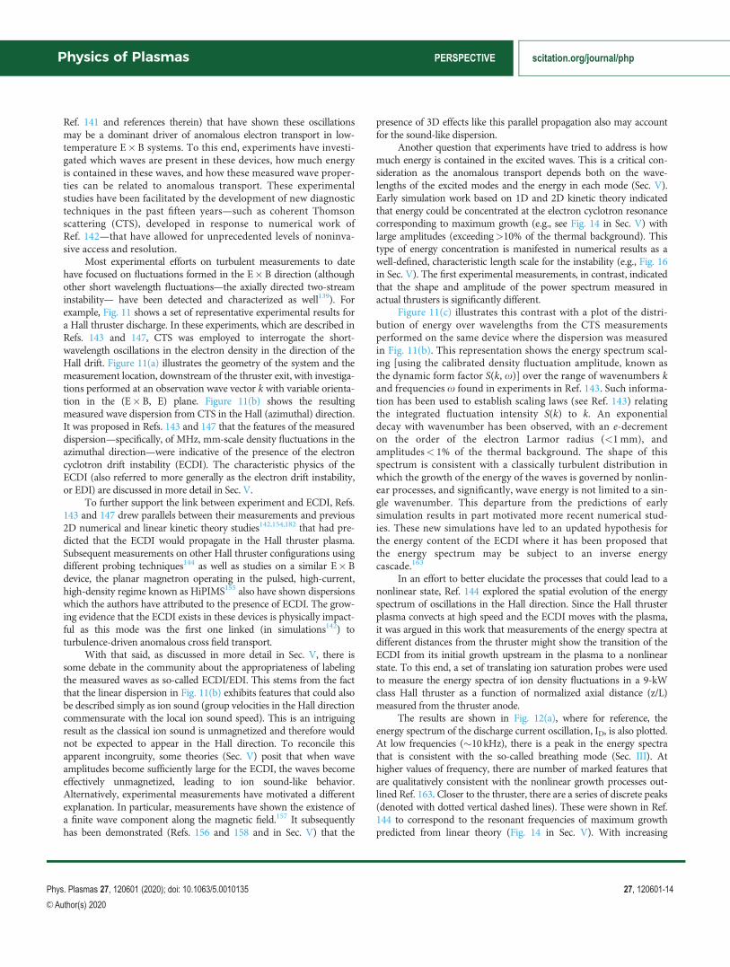
In an effort to better elucidate the processes that could lead to anonlinear state, Ref. 144 explored the spatial evolution of the energyspectrum of oscillations in the Hall direction. Since the Hall thrusterplasma convects at high speed and the ECDI moves with the plasma,it was argued in this work that measurements of the energy spectra atdifferent distances from the thruster might show the transition of theECDI from its initial growth upstream in the plasma to a nonlinearstate. To this end, a set of translating ion saturation probes were usedto measure the energy spectra of ion density fluctuations in a 9-kWclass Hall thruster as a function of normalized axial distance (z/L)measured from the thruster anode.
The results are shown in Fig. 12(a), where for reference, theenergy spectrum of the discharge current oscillation, ID, is also plotted.At low frequencies (�10 kHz), there is a peak in the energy spectrathat is consistent with the so-called breathing mode (Sec. III). Athigher values of frequency, there are number of marked features thatare qualitatively consistent with the nonlinear growth processes out-lined Ref. 163. Closer to the thruster, there are a series of discrete peaks(denoted with dotted vertical dashed lines). These were shown in Ref.144 to correspond to the resonant frequencies of maximum growthpredicted from linear theory (Fig. 14 in Sec. V). With increasing
Physics of Plasmas PERSPECTIVE scitation.org/journal/php
Phys. Plasmas 27, 120601 (2020); doi: 10.1063/5.0010135 27, 120601-14
VC Author(s) 2020
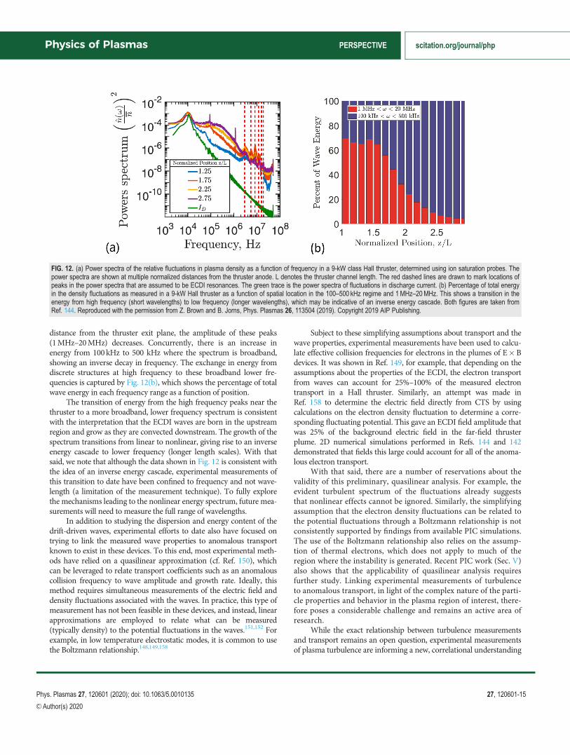
distance from the thruster exit plane, the amplitude of these peaks(1MHz–20MHz) decreases. Concurrently, there is an increase inenergy from 100 kHz to 500 kHz where the spectrum is broadband,showing an inverse decay in frequency. The exchange in energy fromdiscrete structures at high frequency to these broadband lower fre-quencies is captured by Fig. 12(b), which shows the percentage of totalwave energy in each frequency range as a function of position.
The transition of energy from the high frequency peaks near thethruster to a more broadband, lower frequency spectrum is consistentwith the interpretation that the ECDI waves are born in the upstreamregion and grow as they are convected downstream. The growth of thespectrum transitions from linear to nonlinear, giving rise to an inverseenergy cascade to lower frequency (longer length scales). With thatsaid, we note that although the data shown in Fig. 12 is consistent withthe idea of an inverse energy cascade, experimental measurements ofthis transition to date have been confined to frequency and not wave-length (a limitation of the measurement technique). To fully explorethe mechanisms leading to the nonlinear energy spectrum, future mea-surements will need to measure the full range of wavelengths.
In addition to studying the dispersion and energy content of thedrift-driven waves, experimental efforts to date also have focused ontrying to link the measured wave properties to anomalous transportknown to exist in these devices. To this end, most experimental meth-ods have relied on a quasilinear approximation (cf. Ref. 150), whichcan be leveraged to relate transport coefficients such as an anomalouscollision frequency to wave amplitude and growth rate. Ideally, thismethod requires simultaneous measurements of the electric field anddensity fluctuations associated with the waves. In practice, this type ofmeasurement has not been feasible in these devices, and instead, linearapproximations are employed to relate what can be measured(typically density) to the potential fluctuations in the waves.151,152 Forexample, in low temperature electrostatic modes, it is common to usethe Boltzmann relationship.148,149,158
Subject to these simplifying assumptions about transport and thewave properties, experimental measurements have been used to calcu-late effective collision frequencies for electrons in the plumes of E�Bdevices. It was shown in Ref. 149, for example, that depending on theassumptions about the properties of the ECDI, the electron transportfrom waves can account for 25%–100% of the measured electrontransport in a Hall thruster. Similarly, an attempt was made inRef. 158 to determine the electric field directly from CTS by usingcalculations on the electron density fluctuation to determine a corre-sponding fluctuating potential. This gave an ECDI field amplitude thatwas 25% of the background electric field in the far-field thrusterplume. 2D numerical simulations performed in Refs. 144 and 142demonstrated that fields this large could account for all of the anoma-lous electron transport.
With that said, there are a number of reservations about thevalidity of this preliminary, quasilinear analysis. For example, theevident turbulent spectrum of the fluctuations already suggeststhat nonlinear effects cannot be ignored. Similarly, the simplifyingassumption that the electron density fluctuations can be related tothe potential fluctuations through a Boltzmann relationship is notconsistently supported by findings from available PIC simulations.The use of the Boltzmann relationship also relies on the assump-tion of thermal electrons, which does not apply to much of theregion where the instability is generated. Recent PIC work (Sec. V)also shows that the applicability of quasilinear analysis requiresfurther study. Linking experimental measurements of turbulenceto anomalous transport, in light of the complex nature of the parti-cle properties and behavior in the plasma region of interest, there-fore poses a considerable challenge and remains an active area ofresearch.
While the exact relationship between turbulence measurementsand transport remains an open question, experimental measurementsof plasma turbulence are informing a new, correlational understanding
FIG. 12. (a) Power spectra of the relative fluctuations in plasma density as a function of frequency in a 9-kW class Hall thruster, determined using ion saturation probes. Thepower spectra are shown at multiple normalized distances from the thruster anode. L denotes the thruster channel length. The red dashed lines are drawn to mark locations ofpeaks in the power spectra that are assumed to be ECDI resonances. The green trace is the power spectra of fluctuations in discharge current. (b) Percentage of total energyin the density fluctuations as measured in a 9-kW Hall thruster as a function of spatial location in the 100–500 kHz regime and 1 MHz–20MHz. This shows a transition in theenergy from high frequency (short wavelengths) to low frequency (longer wavelengths), which may be indicative of an inverse energy cascade. Both figures are taken fromRef. 144. Reproduced with the permission from Z. Brown and B. Jorns, Phys. Plasmas 26, 113504 (2019). Copyright 2019 AIP Publishing.
Physics of Plasmas PERSPECTIVE scitation.org/journal/php
Phys. Plasmas 27, 120601 (2020); doi: 10.1063/5.0010135 27, 120601-15
VC Author(s) 2020
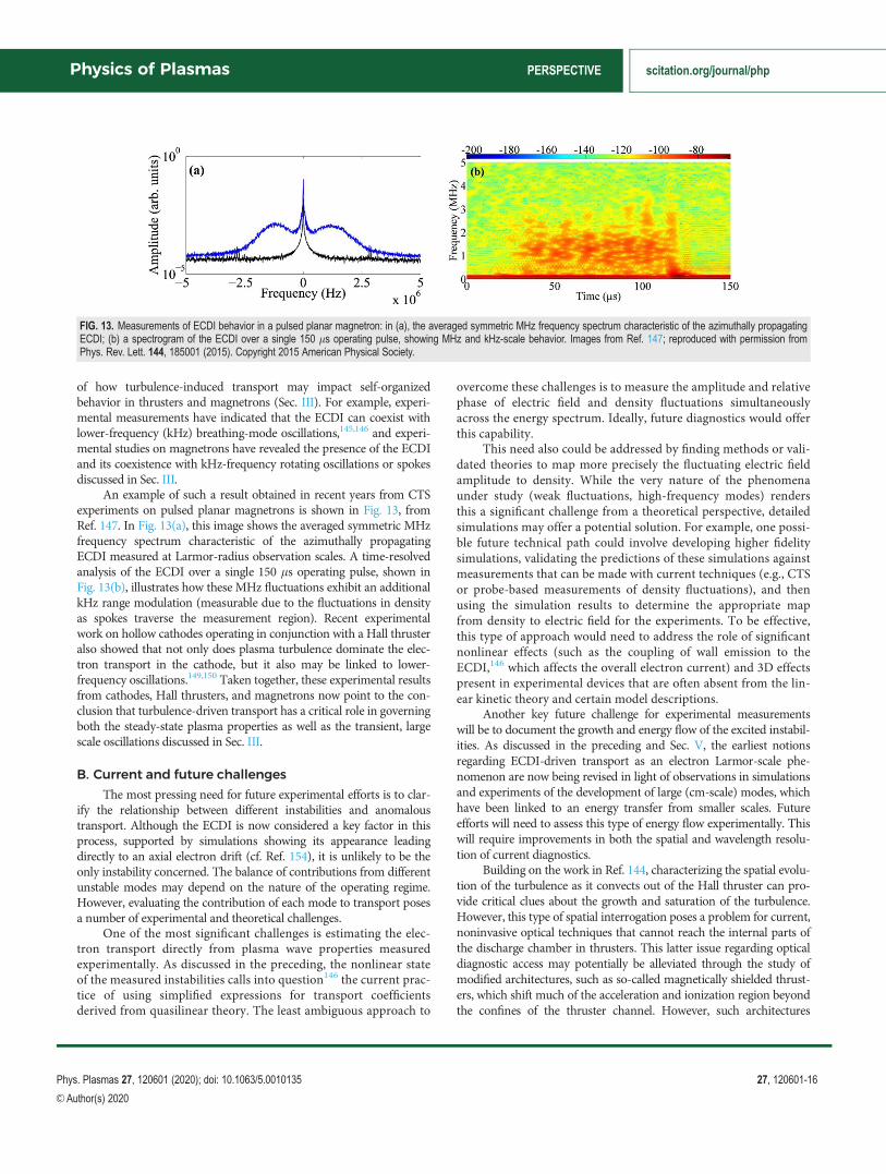
of how turbulence-induced transport may impact self-organizedbehavior in thrusters and magnetrons (Sec. III). For example, experi-mental measurements have indicated that the ECDI can coexist withlower-frequency (kHz) breathing-mode oscillations,145,146 and experi-mental studies on magnetrons have revealed the presence of the ECDIand its coexistence with kHz-frequency rotating oscillations or spokesdiscussed in Sec. III.
An example of such a result obtained in recent years from CTSexperiments on pulsed planar magnetrons is shown in Fig. 13, fromRef. 147. In Fig. 13(a), this image shows the averaged symmetric MHzfrequency spectrum characteristic of the azimuthally propagatingECDI measured at Larmor-radius observation scales. A time-resolvedanalysis of the ECDI over a single 150 ls operating pulse, shown inFig. 13(b), illustrates how these MHz fluctuations exhibit an additionalkHz range modulation (measurable due to the fluctuations in densityas spokes traverse the measurement region). Recent experimentalwork on hollow cathodes operating in conjunction with a Hall thrusteralso showed that not only does plasma turbulence dominate the elec-tron transport in the cathode, but it also may be linked to lower-frequency oscillations.149,150 Taken together, these experimental resultsfrom cathodes, Hall thrusters, and magnetrons now point to the con-clusion that turbulence-driven transport has a critical role in governingboth the steady-state plasma properties as well as the transient, largescale oscillations discussed in Sec. III.
B. Current and future challenges
The most pressing need for future experimental efforts is to clar-ify the relationship between different instabilities and anomaloustransport. Although the ECDI is now considered a key factor in thisprocess, supported by simulations showing its appearance leadingdirectly to an axial electron drift (cf. Ref. 154), it is unlikely to be theonly instability concerned. The balance of contributions from differentunstable modes may depend on the nature of the operating regime.However, evaluating the contribution of each mode to transport posesa number of experimental and theoretical challenges.
One of the most significant challenges is estimating the elec-tron transport directly from plasma wave properties measuredexperimentally. As discussed in the preceding, the nonlinear stateof the measured instabilities calls into question146 the current prac-tice of using simplified expressions for transport coefficientsderived from quasilinear theory. The least ambiguous approach to
overcome these challenges is to measure the amplitude and relativephase of electric field and density fluctuations simultaneouslyacross the energy spectrum. Ideally, future diagnostics would offerthis capability.
This need also could be addressed by finding methods or vali-dated theories to map more precisely the fluctuating electric fieldamplitude to density. While the very nature of the phenomenaunder study (weak fluctuations, high-frequency modes) rendersthis a significant challenge from a theoretical perspective, detailedsimulations may offer a potential solution. For example, one possi-ble future technical path could involve developing higher fidelitysimulations, validating the predictions of these simulations againstmeasurements that can be made with current techniques (e.g., CTSor probe-based measurements of density fluctuations), and thenusing the simulation results to determine the appropriate mapfrom density to electric field for the experiments. To be effective,this type of approach would need to address the role of significantnonlinear effects (such as the coupling of wall emission to theECDI,146 which affects the overall electron current) and 3D effectspresent in experimental devices that are often absent from the lin-ear kinetic theory and certain model descriptions.
Another key future challenge for experimental measurementswill be to document the growth and energy flow of the excited instabil-ities. As discussed in the preceding and Sec. V, the earliest notionsregarding ECDI-driven transport as an electron Larmor-scale phe-nomenon are now being revised in light of observations in simulationsand experiments of the development of large (cm-scale) modes, whichhave been linked to an energy transfer from smaller scales. Futureefforts will need to assess this type of energy flow experimentally. Thiswill require improvements in both the spatial and wavelength resolu-tion of current diagnostics.
Building on the work in Ref. 144, characterizing the spatial evolu-tion of the turbulence as it convects out of the Hall thruster can pro-vide critical clues about the growth and saturation of the turbulence.However, this type of spatial interrogation poses a problem for current,noninvasive optical techniques that cannot reach the internal parts ofthe discharge chamber in thrusters. This latter issue regarding opticaldiagnostic access may potentially be alleviated through the study ofmodified architectures, such as so-called magnetically shielded thrust-ers, which shift much of the acceleration and ionization region beyondthe confines of the thruster channel. However, such architectures
FIG. 13. Measurements of ECDI behavior in a pulsed planar magnetron: in (a), the averaged symmetric MHz frequency spectrum characteristic of the azimuthally propagatingECDI; (b) a spectrogram of the ECDI over a single 150 ls operating pulse, showing MHz and kHz-scale behavior. Images from Ref. 147; reproduced with permission fromPhys. Rev. Lett. 144, 185001 (2015). Copyright 2015 American Physical Society.
Physics of Plasmas PERSPECTIVE scitation.org/journal/php
Phys. Plasmas 27, 120601 (2020); doi: 10.1063/5.0010135 27, 120601-16
VC Author(s) 2020
induce modifications to the plasma which further complicate physicalinterpretation.
Future efforts to study energy flow also will require an expandedcapability to interrogate a wider range of length scales (1mm < k< 1 cm) than currently can be accessed with state-of-the-art methods.These measurements similarly should have the ability to characterizeall three dimensions of propagation of the waves in order to assess thespatial direction of energy flow. Given that there is evidence of cou-pling between the turbulence and low-frequency, self-organized struc-tures, these future diagnostics also should have the capability tomeasure turbulence properties on the timescale of the lower frequencymodes discussed in Sec. III (i.e.,�100 kHz).
As the sophistication of diagnostics continues to grow, the insightthat emerges from experiments must continue be leveraged to informimproved, predictive kinetic modeling. The comparison betweenexperiments (measuring 3D phenomena) and numerical simulationresults can only truly be considered valid if the simulations can eventu-ally reach a sufficient level of sophistication, accounting for (i) thetime scales needed for the study of fast and slow waves, (ii) the fullrange of spatial scales (from electron Larmor radius-scales to centimet-ric scales of large-scale fluid turbulence), and (iii) the 3D plasma envi-ronment itself. An example of the importance of this convergence isillustrated in the following way. Numerical work from a large numberof groups (involving 1D, 2D PIC codes) uniformly show two persistentfeatures for the ECDI-like fluctuations developing in the region of theE�B drift: (i) the establishment of a single dominant length scale forthe mode (<1mm), and (ii) the alignment of these fluctuations pri-marily along the azimuthal direction (but with a positive axial wavevector component). In contrast, more recent 3D simulations (see Sec.VII) show clearly (i) the weakening of the coherent nature of theECDI fluctuations (which become more compatible with a broadbandstructure, already established in CTS experiments) and (ii) the disap-pearance of a preferred propagation direction outwards. The differ-ences already observable between 1D, 2D, and 3D simulation resultsare strong evidence of the need for 3D simulation codes which canprovide a more solid basis for future numerical/experimentalcomparisons.
Beyond kinetic simulations, experimental measurements also willbe critical for guiding fluid-based attempts to approximate the effectsof the turbulence on background plasma properties (Sec. VI). Indeed,while fluid simulations cannot capture the kinetic effects of the wavesdirectly, these processes can be represented with approximate closuremodels. The fidelity of these closure models in turn depends directlyon an understanding of the evolution and growth of macroscopicproperties of the turbulence such as the total wave energy. Recentwork on the study of anomalous electron transport in the hollow cath-ode, the electron source for Hall thrusters, could serve as a potentialroadmap for future efforts.
In these previous works, experimental measurements of the evo-lution of a turbulence and anomalous transport in both space andtime were leveraged to guide the development of fluid codes thatincluded equations to approximate the effects of plasma turbulence onelectron resistivity.84,149,150,153,164,165 These models in turn have beensuccessfully used to simulate the plasma in both the interior and exte-rior of the cathode. A similar approach could be applied for modelingthe effects of turbulence-induced anomalous transport in E�B devi-ces, though, unlike in the cathode studies where the turbulence lent
itself to a simple 1D description, closure models for the effects ofE�B modes likely will be more nuanced. Before it is possible todevelop approximations for these effects in a fluid framework, manyunresolved questions related to the turbulence discussed above (3Dpropagation, inverse energy cascades, etc.) will need to be resolved.
C. Advances in science and technology to meetchallenges
Many of these technical challenges outlined in Sec. IVB may beaddressed by building on existing diagnostics techniques. For example,the current implementation of CTS was designed for the purpose ofaccessing shorter wavelengths (<2mm) as this is where PIC simula-tions suggested the ECDI should exist. In principle, the CTS techniquecan be modified to access a wider range of wavelengths and thereforecapture the relevant content at longer wavelengths. This increase inwavelength range comes at the expense of spatial resolution (as thereis an approximate inverse relationship between measurable wavelengthand spatial resolution). Future efforts should focus on expanding thecapabilities of CTS while maintaining high spatial resolution. Withthat said, assuming CTS still will have a practical lower bound in wave-length, probes can be used to fill in information about the energy spec-tra of oscillations at longer length scales.
The recent development of a sensitive incoherent Thomson scat-tering (ITS) platform136 allowing investigations of cathode,159
thruster,160 and magnetron plasmas161 gives access to information thathas long been lacking regarding background electron properties (tem-perature and drift) in these sources. This provides crucial informationthat can impact the predicted growth and density fluctuations in themeasured waves. It is hoped that the coupling of improved CTS andITS can be an important tool for validating basic physical understand-ing regarding the conditions in which certain instabilities arise. Anunderstanding of the velocity distribution of electrons also may helplead to refined expressions for relating measured wave properties totransport.176 Similarly, there have been recent advances in techniquesbased on laser induced fluorescence that have allowed, for the firsttime, the noninvasive measurement of anomalous electron transportinside Hall thrusters.166 These data will be crucial for providing“ground truth” for the local transport that can be used as a point ofcomparison to determine if the contributions from instabilities, if any,are sufficient to explain the electron dynamics.
As discussed in the preceding, in order to directly estimate trans-port from the measured instabilities, it is necessary to make measure-ments of the electric field fluctuations and electron densityfluctuations simultaneously. Both CTS and probe-based measure-ments that have been employed to date, however, have focused oncharacterizing oscillations in the plasma density. In principle, probescould be used to measure both potential and density (with limited spa-tial resolution), though probes are known to perturb the local plasmastate. Alternatively, there are diagnostic techniques from the study ofhigher energy plasmas such as Stark broadening that may offer apotential technical path for characterizing the electric field fluctuationsnoninvasively and at small wavelengths. There are several technicalhurdles stemming from accessibility and signal to noise ratio thatmust first be overcome, however, before these methods can be appliedto low temperature systems.
Numerical simulations (and, as described above, 3D simulationsin particular,) may offer a key capability for bypassing the need to
Physics of Plasmas PERSPECTIVE scitation.org/journal/php
Phys. Plasmas 27, 120601 (2020); doi: 10.1063/5.0010135 27, 120601-17
VC Author(s) 2020

make direct measurements of electric field. Before these can be used,these simulations must first be validated against measurements of boththe background and wave properties. With this in mind, establishingthe error bars of invasive and noninvasive techniques will be impor-tant for future progress in the use of models to inform experiment. Itwill be necessary to explain and quantify differences observed betweenprobes and optical techniques for the measurement of electron proper-ties, and to establish on what data future simulation efforts should bevalidated, given the limitations and challenges of different diagnostics.As an example, measurements of the electron energy distributionfunction using ITS rely on obtaining a sufficiently high signal-to-noiseratio, which is difficult for plasma densities in the range of 1016 m�3,even now with recent diagnostics improvements. This requirementwould ultimately affect the detection of features pertaining to the spec-tral wings such as high-energy electron populations.
Combining information from complementary diagnostics—onelectron density fluctuations, EEDFs, absolute electron density, elec-tron temperature, and ion properties—is required to refine modelsand theory, and gradual progress is being made on this front. Thecombination of multiple diagnostics running simultaneously on thesame test device would provide an ensemble of useful data for simula-tions. As noted above, a concerted attempt to bridge the gap betweenmeasurements at large scales using probes, and small-scale measure-ments using CTS, could be an important contribution toward estab-lishing the presence (or absence) of dominant wavenumbers inanomalous transport. As these experimental capabilities become avail-able, it will be necessary to analyze experimental findings coupled withsufficiently advanced numerical codes, still under development, whichare capable of capturing 3D plasma features.
D. Conclusion
There has been substantial progress in the past decade in experi-mental methods and diagnostics that have yielded new insights intothe role of plasma turbulence in E�B devices. The detection andin-depth study of different types of instabilities present in such devices,such as the ECDI, ion acoustic turbulence, spokes and high-frequency,long-wavelength modes170,171 have contributed to our understandingof basic physics. Several challenges remain, including reconcilingexperimental data with simulation predictions, understanding the lim-itations of invasive and noninvasive diagnostics, and studying thegrowth and nonlinear evolution of the observed turbulence and anom-alous transport in E�B devices. Efforts in diagnostic developmentand analysis are under way to help address these challenges. Lookingto the future, the development of standardized test devices, particularlyones that can be shared internationally, could enable coordinated andmore impactful efforts that leverage the diagnostic capabilities of mul-tiple institutions. Similarly, closer collaborations between experimen-talists and modelers will be critical for establishing the validity of codescurrently under development, understanding the role played bydifferent instabilities in thruster operation, and guiding the designof future E�B devices and modeling efforts to study plasma tur-bulence. It has become evident that understanding features ofplasma turbulence measurable experimentally, and the contribu-tion of different instabilities to transport, will also ultimatelyrequire 3D numerical code results for comparison. Parallel pro-gress in both diagnostic development and numerical simulationcapability is a clear objective for the future.
V. ELECTRON DRIFT INSTABILITIES IN E�B PLASMAS:MECHANISMS, NONLINEAR SATURATION ANDTURBULENT TRANSPORT
Andrei Smolyakov1, Jean-Pierre Boeuf2, and Trevor Lafleur31University of Saskatchewan, 116 Science Place, Saskatoon, SK
S7N 5E2, Canada2LAPLACE, Universit�e de Toulouse, CNRS, INPT, UPS, 118 Route
de Narbonne, 31062 Toulouse, France3PlasmaPotential, Entry 29, 5/1 Moore Street, Canberra ACT 2601,
Australia
A. State-of-the-art and recent progress
Electron transport across the magnetic field in devices employingmagnetic filter configurations is typically anomalous and exceeds thetransport due to classical collisions of electrons with other particle spe-cies in the plasma. Typically, the inclusion of wall-collisions (near-wallconductivity) is not sufficient to explain experimental values inside thechannel. Moreover, the electron current significantly exceeds the clas-sical value outside the channel, where the near-wall conductivity isabsent. Thus, it is widely believed that the anomalous transportenhancement is due to convective transport and scattering of electronsdue to turbulent plasma fluctuations. The nature of such fluctuationsis neither well understood, nor does there exist any validated theoreti-cal model that can be used to predict the turbulent electron transportfor specific thruster conditions.
The electron drift instability (EDI) due to the electron drift hasattracted a lot of attention recently as a possible instability and anoma-lous transport mechanism in Hall thrusters.141,142,172–176 Such interestwas also stimulated by experimental observations of small scale fluctu-ations where the wave-frequency is found to be linear with thewave-vector, which is consistent with the ion sound wave dispersionrelationship, see Fig. 11.
Studies of this instability were started much earlier in relation tothe problem of anomalous resistivity to explain the width of collision-less shock waves in space and turbulent heating experiments.177–180
The instability occurs as a result of the differential drift of electronswith respect to unmagnetized ions, when the Doppler frequency shiftresults in an overlap of the kinetic resonances of electron cyclotron(Bernstein) type modes with the ion sound branch. As a kinetic insta-bility, it does not require plasma or magnetic field gradients, and ispurely based on the electron E�B drift in crossed magnetic and elec-tric fields. When applied to Hall thrusters, the EDI is of great interestin the region of large electric field, where one can expect that thekinetic instability due to this large electric field will dominate overother instability mechanisms, such as plasma gradients andcollisions.74
The genesis of EDI mechanisms can be tracked down to the mag-netized Buneman instability in cold plasmas.181 This is the reactiveinstability which occurs as a result of the interaction of two stablemodes: the upper hybrid resonance, and the low-frequency ion oscilla-tions, x2 ¼ xpi
2 (which is the short wavelength limit of the ion soundmode). The upper hybrid mode is Doppler shifted by the electronvE ¼ E� B=B2 drift so it moves into the ion plasma ðxpiÞ frequencyrange. In the plasma with a finite electron temperature, the overlap-ping modes are the Bernstein and ion sound modes, xce � kyvE ’ x,so that the approximate resonance condition is kyvE ’ xce, where ky
Physics of Plasmas PERSPECTIVE scitation.org/journal/php
Phys. Plasmas 27, 120601 (2020); doi: 10.1063/5.0010135 27, 120601-18
VC Author(s) 2020

is the wavevector in the direction of the E� B drift, which corre-sponds to the azimuthal direction in Hall thruster and magnetrongeometries, and xce is the electron cyclotron frequency. When oneallows electron motion along the magnetic field, an additional instabil-ity appears due to the finite value of the wavevector along the magneticfield, kz 6¼ 0; the so-called Modified Two-Stream Instability. Thisinstability was also considered in the original paper,181 so below it willbe called the modified Buneman two-stream instability (MBTSI),which has the largest growth rate for relatively small values ofkz � ky ’ xce=vE .
For purely perpendicular propagation and finite electron temper-ature, there a exists a set of multiple narrow bands of reactively unsta-ble modes near the resonances x� kyvE �mxce ¼ 0, m ¼ 1; 2;…:.When electron parallel motion is included, for finite kz , kinetic(Landau) resonances become possible leading to dissipative instabil-ities at x� kyvE0 � kzvjj �mxce ’ 0. For kzvTe � xce; the kineticresonances broaden and eventually overlap, resulting in an instabilityequivalent to the ion sound instability in an unmagnetized plasma, butdriven instead by the electron E�B beam flow,156,174,182 see Fig. 14.
The various limits of this linear instability (usually referred to as theelectron cyclotron drift instability or ECDI) are well studied; how-ever, nonlinear behavior and saturation are much less understood,especially for small or zero kz when linear Landau interactions dueto particle motion along the magnetic field are not possible. Someearlier studies179 have concluded that at a certain amplitude, thecyclotron resonances are washed out by nonlinear effects and theinstability proceeds as an ordinary ion sound wave instability asfound in unmagnetized plasmas until it is saturated by linear ornonlinear Landau damping by ions. Other studies haveargued183,184 that electron trapping in the magnetic field remainsimportant, making the nonlinear stage different from that of anunmagnetized plasma ion sound instability. Alternative mecha-nisms (different from cyclotron and kinetic resonances) have alsobeen proposed185 to explain the nonlinear instability; hence, below,we refer to the general nonlinear regime of this instability as theelectron drift instability (EDI).
The ECDI/EDI is a very robust instability and can easily be seeneven in the simplest versions of 1D PIC simulations of magnetizedplasmas, e.g., see the cold plasma example in Ref. 186. In the contextof the anomalous transport in Hall thrusters, it has been studied in 1Dsimulations,141,163,174 2D axial–azimuthal simulations,142,173,176,187 and2D radial–azimuthal simulations.146,188,190 Typically, in such simula-tions, significant anomalous transport in the axial direction as well asvery effective electron heating are observed. In 1D versions, the insta-bility occurs for perturbations propagating strictly in the direction ofthe electron drift and typically shows up in the simulations as a fairlycoherent nonquasineutral mode with strongly peaked ion density per-turbations which are noticeably larger in amplitude than those of theelectron density which remains relatively smooth,141 see Fig. 15.
Quasilinear models of electron transport due to the EDI have beenproposed175,193–195 based on the assumption that the underlying turbu-lence is ion-acoustic as is in the case without the magnetic field. In thequasilinear approximation, the magnitude of the turbulent flux was esti-mated as C ¼ h~n~Eyi=B0, using relationships between the density andelectric field fluctuations from the linear theory of ion–sound instabilityin unmagnetized plasma. The wave amplitude at saturation in thesemodels,175,193–195 was estimated from the linear wave kinetic equationfor the evolution of the wave energyWk ¼ jEj2k convected axially by theion flow (with the wave group velocity in the axial direction) and a com-bination of the linear Landau damping from warm ions and nonlinearion trapping. However, since the wave kinetic equation is linear in thewave energy Wk; the result is sensitive to the choice of the initial“reference” value at some given location. A further refinement was donein Ref. 193, based on the comparison with PIC simulations which showsubstantial non-Maxwellian distribution functions for the electrons.Using non-Maxwellian distribution functions193 reduces the ion-soundgrowth rate, bringing the estimate of the fluctuation level down and incloser agreement with magnitudes expected experimentally.
Experimentally, it was found that fluctuations near the accelera-tion region exhibit discrete cyclotron resonances characteristic of theECDI while downstream the turbulence evolves into the linear disper-sion relation typical of the long-wavelength ion soundmodes.144,196
B. Current and future challenges
There are significant challenges in numerical simulations of theelectron drift instability as well as in the theoretical understanding and
FIG. 14. The linear growth rate of the ECDI, for various values of the wave-vectoralong the magnetic field kzkD of 0.01, 0.02, 0.04, and 0.08, respectively. The firstroot from the left is the modified two-stream instability (MTSI) (m¼ 0), and subse-quent roots are the kinetic resonance modes with ky=k0 ’ m ¼ 1; 2;…, wherek0 ¼ xce=vE . The transition to unmagnetized ion-sound instability corresponds tokzkD � 0:08 for the parameters in Ref. 190. Reproduced with permission fromJanhunen et al., Phys. Plasmas 25, 082308 (2018). Copyright 2018 AIP Publishing.
FIG. 15. Ion and electron density perturbation as a function of the azimuthal posi-tion (cm) in 1D simulations of EDI. Reproduced with the permission from J.-P.Boeuf, J. Appl. Phys. 121, 011101 (2017).141 Copyright 2017 AIP Publishing.
Physics of Plasmas PERSPECTIVE scitation.org/journal/php
Phys. Plasmas 27, 120601 (2020); doi: 10.1063/5.0010135 27, 120601-19
VC Author(s) 2020
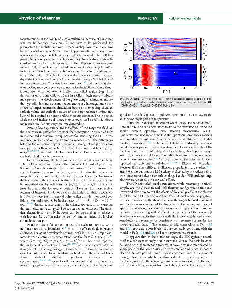
interpretations of the results of such simulations. Because of computerresource limitations, many simulations have to be performed forparameters far realistic: reduced dimensionality, low resolution, andlimited spatial coverage. Several model approximations for ionizationsources and energy particle losses are also often used. The EDI hasproved to be a very effective mechanism of electron heating, leading toa fast rise in the electron temperature. In the 1D periodic domain (andin some 2D) simulations, a “virtual” axial acceleration length and/orinelastic collision losses have to be introduced to achieve a stationarytemperature state. The level of anomalous transport may becomedependent on the mechanism of how the electrons are “cooled down”in these simulations. Concerns have been raised168 that the strong elec-tron heating may be in part due to numerical instabilities. Many simu-lations are performed over a limited azimuthal region (e.g., in adomain around 1 cm wide vs 30 cm in reality). Such narrow widthsmay prevent the development of long-wavelength azimuthal modesthat typically dominate the anomalous transport. Investigations of theeffects of larger azimuthal simulation boxes and extending them torealistic values are difficult because of computer resource limitations,but will be required to become relevant to experiments. The inclusionof elastic and inelastic collisions, ionization, as well as full 3D effectsmake such simulations very resource demanding.
Among basic questions are the effects of the magnetic field onthe electrons, in particular, whether the description in terms of fullyunmagnetized ion sound is appropriate for modeling the EDI in thenonlinear regime and on the saturation mechanisms. The differencesbetween the ion sound type turbulence in unmagnetized plasmas andin a plasma with a magnetic field have been much debated previ-ously183,198,199 without definitive conclusions that can be directlyapplied to Hall thruster parameters.
In the linear case, the transition to the ion sound occurs for finitevalues of the wave vector along the magnetic field with kzvTe’xce.Several PIC simulations were performed however, in 1D (azimuthal)and 2D (azimuthal–axial) geometry, where the direction along themagnetic field is ignored, kz ¼ 0, and thus the linear mechanism ofthe transition to the ion sound is absent. The cyclotron resonances canbe smoothed out by collisions for ð�=XceÞk2q2
e > p=2, forcing theinstability into the ion–sound regime. However, for most typicalregimes of interest, simulations were collisionless or almost collision-less. For the most part, numerical noise, which can play the role of col-lisions, was estimated to be in the range of �n ¼ 5� ð10�5 � 10�6Þxpe;
197,198 therefore, according to the criteria above, it is not expectedthat numerical noise can result in electron demagnetization. The statis-tical fluctuations �1=
ffiffiffiffiNp
however can be essential in simulationswith low numbers of particles per cell, N , and can affect the level ofanomalous transport.
Another reason for smoothing out the cyclotron resonances isnonlinear resonance broadening200 which can effectively demagnetizeelectrons. For short-wavelength regimes, with kqe > 1, a simple esti-mate for the electron demagnetization has the form N > ðkqeÞ�1,163where N � ðx2
pe=X2ceÞW=ðn0TeÞ, W ¼ E2=8p. It has been reported
that in some 1D and 2D simulations163,190 this criterion is not satisfied(though not with a large margin). Consistent with this, the nonlinearevolution of the electron cyclotron instability in these simulationsshows distinct electron cyclotron resonances atkyvE ¼ mxce;
163,190–192 as well as the ion sound modes features, e.g.,mode propagation with a phase velocity of the order of the ion sound
speed and oscillations (and nonlinear harmonics) at x ¼ xpi in theshort wavelength part of the spectrum.
Azimuthal-radial simulations, in which the kz (in the radial direc-tion) is finite, and the linear mechanism to the transition to ion soundshould remain operative, also showing inconclusive results.Quasicoherent nonlinear waves at the cyclotron resonances movingwith roughly the ion sound velocity have been observed in highlyresolved simulations,190 similar to the 1D case, with strongly nonlinearcnoidal waves peaked at short wavelengths. The important role of themodified two-stream instability, due to a finite kz , leading to stronglyanisotropic heating and large scale radial structures in the anomalouscurrent, was emphasized.190 Various values of the effective kz werereported in different simulations.24,193–195 Effects of SecondaryElectron Emission (SEE) and different propellants were studied24,189
and it was shown that the EDI activity is affected by the reduced elec-tron temperature due to sheath cooling. Besides, SEE induces largeelectron transport due to near-wall effects.
The 2D azimuthal–axial simulations, while remaining relativelysimple, are the closest to real Hall thruster configurations (in someways) and allow one to test the effects of the axial profile of the electricfield (the main EDI driver) and the effects of axial mode propagation.In these simulations, the direction along the magnetic field is ignoredand the linear mechanism of the transition to the ion sound does notapply. Nevertheless, these simulations reveal strongly coherent nonlin-ear waves propagating with a velocity of the order of the ion soundvelocity, a wavelength that scales with the Debye length, and a waveamplitude that seems to be consistent with estimates from the iontrapping mechanism.187 The azimuthal–axial simulations in Refs. 193and 176 report transport levels that are generally consistent with themodel in Refs. 174 and 201 and some experimental results.
It appears that in the nonlinear stage, the EDI typically revealsitself as a coherent strongly nonlinear wave, akin to the periodic cnoi-dal wave with characteristic features of wave breaking manifested bysharp peaks in the ion density and with smaller and much smootherelectron density perturbations. This is consistent with the regime ofunmagnetized ions, which therefore exhibit the tendency of wavebreaking (similar to the neutral gas sound wave modes), while the elec-trons remain largely magnetized and show a smoother density. The
FIG. 16. 2D axial–azimuthal maps of the azimuthal electric field (top) and ion den-sity (bottom), reproduced with permission from Plasma Sources Sci. Technol. 28,105010 (2019).204 Copyright 2019 IOP Publishing.
Physics of Plasmas PERSPECTIVE scitation.org/journal/php
Phys. Plasmas 27, 120601 (2020); doi: 10.1063/5.0010135 27, 120601-20
VC Author(s) 2020

coherent, almost single mode, emerging in many numerical simula-tions, e.g., see Fig. 16, presents a challenge to the application of quasi-linear theory, which assumes an ensemble of weakly nonlinear, widespectrum overlapping modes. The anomalous transport estimate inthe form C ¼ h~n~Eyi=B0 assumes that the dominant electron currentis due to the E�B drift of magnetized electrons, which appears to beinconsistent with the regime of unmagnetized electrons for the ionsound instability in the absence of a magnetic field, although simula-tions187,193 seem to show that this estimate is roughly valid.
C. Conclusion
For typical parameters in the acceleration region, the electrondrift velocity vE ¼ E0=B0 becomes comparable to the electron thermalvelocity (and much larger than the ion sound velocity, vE ’ vTe cs).In such regimes, nonlinear electron and ion dynamics become stronglynonlinear202 and numerical modeling is critical for theoreticaladvancement and validation. This regime is far from the marginal sta-bility criteria and normally a broad spectrum of excited modes isexpected. Nevertheless, many PIC simulations demonstrate the excita-tion of a highly coherent mode and very effective electron heating. Themechanism of anomalous transport and heating in the electron inter-action with quasicoherent waves and the role of numerical noise haveto be understood. Several simulations indicate that secondary nonlin-ear processes take place resulting in the appearance of long-wavelength modes (similar to modulational instabilities) on top of thequasicoherent mode. The large scale modes are typically expected toprovide large contributions to the anomalous transport and need to beresolved for realistic parameters. Therefore, simulations with largerspatial boxes representative of realistic geometrical dimensions areimportant and will require substantial computer resources.
High-performance large scale simulations need to explore howthe current results (with low resolution and narrow simulation boxes)can be extrapolated to real-sized devices. Many reported simulationsfrom different groups have been performed with varying approxima-tions and assumptions, which makes the comparison more difficultand inconclusive. Recently, a broad collaborative effort between severalgroups has been initiated to investigate the accuracy and convergenceof the results of different numerical codes203,204 under the same condi-tions. A 2D axial–azimuthal particle-in-cell benchmark for low-temperature partially magnetized plasmas instabilities has beenrecently completed.204 The results obtained for this benchmark showgood agreement between the different codes from several groups.
One has to note also that the ECDI is only one of a number ofinstabilities that could be relevant to Hall thrusters, and more gener-ally, to E�B devices; e.g., resistive axial and azimuthal instabilities canbe important as well as azimuthal Simon–Hoh type modes74,75,107 thatare described in Secs. III and VI.
VI. FLUID AND HYBRID (FLUID–KINETIC) MODELING OFE�B DISCHARGES
Andrei Smolyakov1, and Ioannis G. Mikellides21University of Saskatchewan, 116 Science Place, Saskatoon, SK
S7N 5E2, Canada2Jet Propulsion Laboratory, California Institute of Technology,
Pasadena, CA, 91109, USA
A. State-of-the-art and recent progress
A major challenge in the modeling of E�B discharges such asthose in the HET has been that the governing processes are inherentlythree-dimensional (3D) and span multiple scales. Specifically, the spa-tiotemporal resolution must span the device length down to the elec-tron Larmor radius (qe) as well as the long timescales associated withthe motion of atoms down to those for the electron motion. Moreover,it has been argued that the species velocity distribution function canbe far from Maxwellian, implying that the nature of plasma instabil-ities in these discharges may be strongly affected by kinetic effects. Iftrue, fully kinetic simulations would be the most comprehensiveapproach to model such conditions. However, in many cases, suchsimulations are as complex as experiments and can be difficult tointerpret. Though petascale computing is now possible, kinetic simula-tions with realistic parameters that span the entire HET domainremain computationally very expensive. Although particle methodsfor all three species in z–h142,173,201 and r–h30,146,206 domains, andeven in 3D,168,169 have indeed been used successfully and have yieldedcritical insight in some cases, they are constrained to restricted spatialand/or temporal domains, which limits our ability to capture the entirerange of physical processes. In HETs for example, though on onehand simulations in the z–h plane can provide a detailed insight intoinstabilities with wave vectors in the E�B and axial directions, theyprovide no information about plasma–wall interactions which areknown to affect the operation of the device. On the other hand, in ther–h domain the simulations cannot take into account the axial varia-tion of the plasma properties and therefore cannot provide insight intohow the transport physics evolves throughout the different regions ofthe channel.
Fluid theory predicts several instabilities that may be responsiblefor turbulence and transport in E�B discharges. In general, fluid sim-ulations that account for plasma turbulence and thus produce self-consistent transport are computationally faster and cheaper comparedto kinetic simulations. Such simulations are also easier to interpret,provide much greater flexibility in separating various physics elements,and are vital in developing intuition of the complex processes thatoccur in plasma discharges. Over the years, fluid models have beenproviding indispensable contributions to the development of nonlinear
FIG. 17. Vorticity structures in axial–azimuthal (z–h) fluid simulations.74
Reproduced with permission from Plasma Phys. Controlled Fusion 59, 014041(2017). Copyright 2017 IOP Publishing.
Physics of Plasmas PERSPECTIVE scitation.org/journal/php
Phys. Plasmas 27, 120601 (2020); doi: 10.1063/5.0010135 27, 120601-21
VC Author(s) 2020
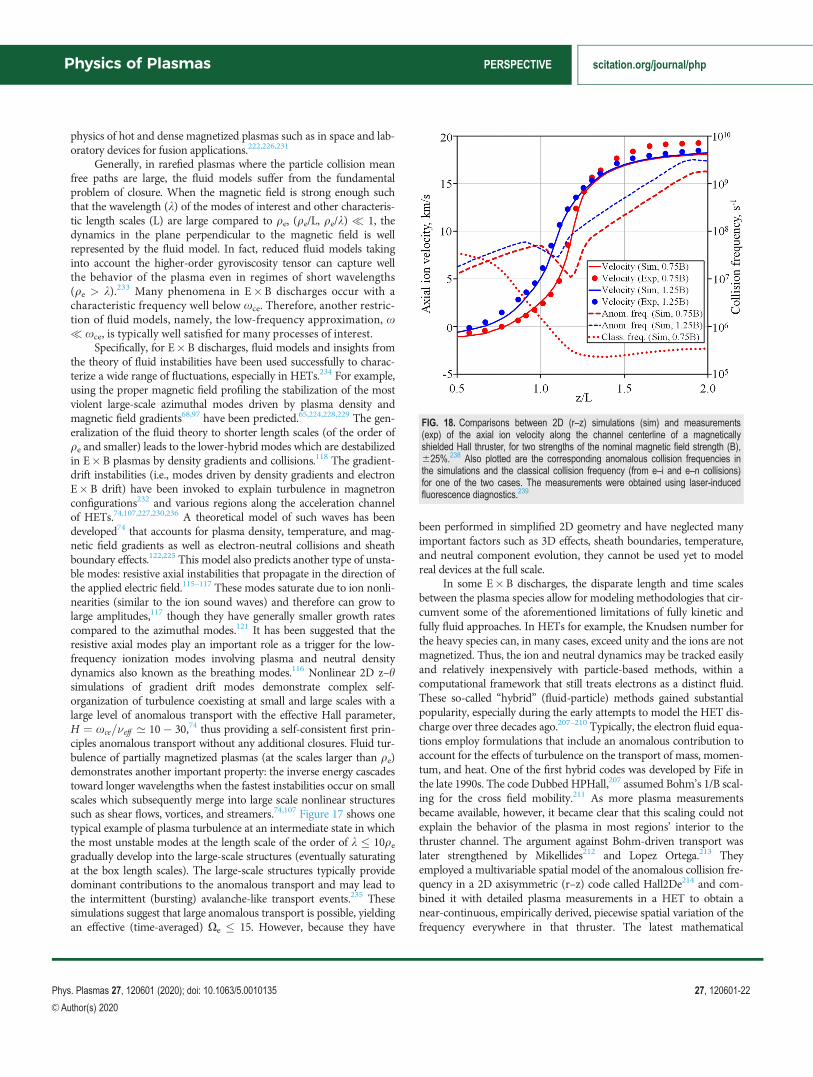
physics of hot and dense magnetized plasmas such as in space and lab-oratory devices for fusion applications.222,226,231
Generally, in rarefied plasmas where the particle collision meanfree paths are large, the fluid models suffer from the fundamentalproblem of closure. When the magnetic field is strong enough suchthat the wavelength (k) of the modes of interest and other characteris-tic length scales (L) are large compared to qe, (qe/L, qe/k) � 1, thedynamics in the plane perpendicular to the magnetic field is wellrepresented by the fluid model. In fact, reduced fluid models takinginto account the higher-order gyroviscosity tensor can capture wellthe behavior of the plasma even in regimes of short wavelengths(qe > k).233 Many phenomena in E�B discharges occur with acharacteristic frequency well below xce. Therefore, another restric-tion of fluid models, namely, the low-frequency approximation, x� xce, is typically well satisfied for many processes of interest.
Specifically, for E�B discharges, fluid models and insights fromthe theory of fluid instabilities have been used successfully to charac-terize a wide range of fluctuations, especially in HETs.234 For example,using the proper magnetic field profiling the stabilization of the mostviolent large-scale azimuthal modes driven by plasma density andmagnetic field gradients68,97 have been predicted.65,224,228,229 The gen-eralization of the fluid theory to shorter length scales (of the order ofqe and smaller) leads to the lower-hybrid modes which are destabilizedin E�B plasmas by density gradients and collisions.118 The gradient-drift instabilities (i.e., modes driven by density gradients and electronE�B drift) have been invoked to explain turbulence in magnetronconfigurations232 and various regions along the acceleration channelof HETs.74,107,227,230,236 A theoretical model of such waves has beendeveloped74 that accounts for plasma density, temperature, and mag-netic field gradients as well as electron-neutral collisions and sheathboundary effects.122,225 This model also predicts another type of unsta-ble modes: resistive axial instabilities that propagate in the direction ofthe applied electric field.115–117 These modes saturate due to ion nonli-nearities (similar to the ion sound waves) and therefore can grow tolarge amplitudes,117 though they have generally smaller growth ratescompared to the azimuthal modes.121 It has been suggested that theresistive axial modes play an important role as a trigger for the low-frequency ionization modes involving plasma and neutral densitydynamics also known as the breathing modes.116 Nonlinear 2D z–hsimulations of gradient drift modes demonstrate complex self-organization of turbulence coexisting at small and large scales with alarge level of anomalous transport with the effective Hall parameter,H ¼ xce=�eff ’ 10� 30,74 thus providing a self-consistent first prin-ciples anomalous transport without any additional closures. Fluid tur-bulence of partially magnetized plasmas (at the scales larger than qe)demonstrates another important property: the inverse energy cascadestoward longer wavelengths when the fastest instabilities occur on smallscales which subsequently merge into large scale nonlinear structuressuch as shear flows, vortices, and streamers.74,107 Figure 17 shows onetypical example of plasma turbulence at an intermediate state in whichthe most unstable modes at the length scale of the order of k � 10qe
gradually develop into the large-scale structures (eventually saturatingat the box length scales). The large-scale structures typically providedominant contributions to the anomalous transport and may lead tothe intermittent (bursting) avalanche-like transport events.235 Thesesimulations suggest that large anomalous transport is possible, yieldingan effective (time-averaged) Xe � 15. However, because they have
been performed in simplified 2D geometry and have neglected manyimportant factors such as 3D effects, sheath boundaries, temperature,and neutral component evolution, they cannot be used yet to modelreal devices at the full scale.
In some E�B discharges, the disparate length and time scalesbetween the plasma species allow for modeling methodologies that cir-cumvent some of the aforementioned limitations of fully kinetic andfully fluid approaches. In HETs for example, the Knudsen number forthe heavy species can, in many cases, exceed unity and the ions are notmagnetized. Thus, the ion and neutral dynamics may be tracked easilyand relatively inexpensively with particle-based methods, within acomputational framework that still treats electrons as a distinct fluid.These so-called “hybrid” (fluid-particle) methods gained substantialpopularity, especially during the early attempts to model the HET dis-charge over three decades ago.207–210 Typically, the electron fluid equa-tions employ formulations that include an anomalous contribution toaccount for the effects of turbulence on the transport of mass, momen-tum, and heat. One of the first hybrid codes was developed by Fife inthe late 1990s. The code Dubbed HPHall,207 assumed Bohm’s 1/B scal-ing for the cross field mobility.211 As more plasma measurementsbecame available, however, it became clear that this scaling could notexplain the behavior of the plasma in most regions’ interior to thethruster channel. The argument against Bohm-driven transport waslater strengthened by Mikellides212 and Lopez Ortega.213 Theyemployed a multivariable spatial model of the anomalous collision fre-quency in a 2D axisymmetric (r–z) code called Hall2De214 and com-bined it with detailed plasma measurements in a HET to obtain anear-continuous, empirically derived, piecewise spatial variation of thefrequency everywhere in that thruster. The latest mathematical
FIG. 18. Comparisons between 2D (r–z) simulations (sim) and measurements(exp) of the axial ion velocity along the channel centerline of a magneticallyshielded Hall thruster, for two strengths of the nominal magnetic field strength (B),625%.238 Also plotted are the corresponding anomalous collision frequencies inthe simulations and the classical collision frequency (from e–i and e–n collisions)for one of the two cases. The measurements were obtained using laser-inducedfluorescence diagnostics.239
Physics of Plasmas PERSPECTIVE scitation.org/journal/php
Phys. Plasmas 27, 120601 (2020); doi: 10.1063/5.0010135 27, 120601-22
VC Author(s) 2020
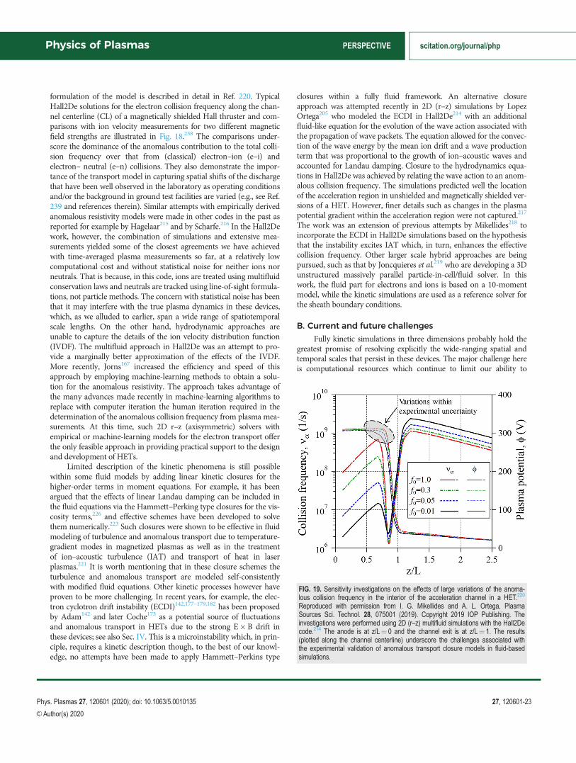
formulation of the model is described in detail in Ref. 220. TypicalHall2De solutions for the electron collision frequency along the chan-nel centerline (CL) of a magnetically shielded Hall thruster and com-parisons with ion velocity measurements for two different magneticfield strengths are illustrated in Fig. 18.238 The comparisons under-score the dominance of the anomalous contribution to the total colli-sion frequency over that from (classical) electron–ion (e–i) andelectron– neutral (e–n) collisions. They also demonstrate the impor-tance of the transport model in capturing spatial shifts of the dischargethat have been well observed in the laboratory as operating conditionsand/or the background in ground test facilities are varied (e.g., see Ref.239 and references therein). Similar attempts with empirically derivedanomalous resistivity models were made in other codes in the past asreported for example by Hagelaar215 and by Scharfe.216 In the Hall2Dework, however, the combination of simulations and extensive mea-surements yielded some of the closest agreements we have achievedwith time-averaged plasma measurements so far, at a relatively lowcomputational cost and without statistical noise for neither ions norneutrals. That is because, in this code, ions are treated using multifluidconservation laws and neutrals are tracked using line-of-sight formula-tions, not particle methods. The concern with statistical noise has beenthat it may interfere with the true plasma dynamics in these devices,which, as we alluded to earlier, span a wide range of spatiotemporalscale lengths. On the other hand, hydrodynamic approaches areunable to capture the details of the ion velocity distribution function(IVDF). The multifluid approach in Hall2De was an attempt to pro-vide a marginally better approximation of the effects of the IVDF.More recently, Jorns167 increased the efficiency and speed of thisapproach by employing machine-learning methods to obtain a solu-tion for the anomalous resistivity. The approach takes advantage ofthe many advances made recently in machine-learning algorithms toreplace with computer iteration the human iteration required in thedetermination of the anomalous collision frequency from plasma mea-surements. At this time, such 2D r–z (axisymmetric) solvers withempirical or machine-learning models for the electron transport offerthe only feasible approach in providing practical support to the designand development of HETs.
Limited description of the kinetic phenomena is still possiblewithin some fluid models by adding linear kinetic closures for thehigher-order terms in moment equations. For example, it has beenargued that the effects of linear Landau damping can be included inthe fluid equations via the Hammett–Perking type closures for the vis-cosity terms,226 and effective schemes have been developed to solvethem numerically.223 Such closures were shown to be effective in fluidmodeling of turbulence and anomalous transport due to temperature-gradient modes in magnetized plasmas as well as in the treatmentof ion–acoustic turbulence (IAT) and transport of heat in laserplasmas.221 It is worth mentioning that in these closure schemes theturbulence and anomalous transport are modeled self-consistentlywith modified fluid equations. Other kinetic processes however haveproven to be more challenging. In recent years, for example, the elec-tron cyclotron drift instability (ECDI)142,177–179,182 has been proposedby Adam142 and later Coche173 as a potential source of fluctuationsand anomalous transport in HETs due to the strong E�B drift inthese devices; see also Sec. IV. This is a microinstability which, in prin-ciple, requires a kinetic description though, to the best of our knowl-edge, no attempts have been made to apply Hammett–Perkins type
closures within a fully fluid framework. An alternative closureapproach was attempted recently in 2D (r–z) simulations by LopezOrtega205 who modeled the ECDI in Hall2De214 with an additionalfluid-like equation for the evolution of the wave action associated withthe propagation of wave packets. The equation allowed for the convec-tion of the wave energy by the mean ion drift and a wave productionterm that was proportional to the growth of ion–acoustic waves andaccounted for Landau damping. Closure to the hydrodynamics equa-tions in Hall2De was achieved by relating the wave action to an anom-alous collision frequency. The simulations predicted well the locationof the acceleration region in unshielded and magnetically shielded ver-sions of a HET. However, finer details such as changes in the plasmapotential gradient within the acceleration region were not captured.217
The work was an extension of previous attempts by Mikellides218 toincorporate the ECDI in Hall2De simulations based on the hypothesisthat the instability excites IAT which, in turn, enhances the effectivecollision frequency. Other larger scale hybrid approaches are beingpursued, such as that by Joncquieres et al.219 who are developing a 3Dunstructured massively parallel particle-in-cell/fluid solver. In thiswork, the fluid part for electrons and ions is based on a 10-momentmodel, while the kinetic simulations are used as a reference solver forthe sheath boundary conditions.
B. Current and future challenges
Fully kinetic simulations in three dimensions probably hold thegreatest promise of resolving explicitly the wide-ranging spatial andtemporal scales that persist in these devices. The major challenge hereis computational resources which continue to limit our ability to
FIG. 19. Sensitivity investigations on the effects of large variations of the anoma-lous collision frequency in the interior of the acceleration channel in a HET.220
Reproduced with permission from I. G. Mikellides and A. L. Ortega, PlasmaSources Sci. Technol. 28, 075001 (2019). Copyright 2019 IOP Publishing. Theinvestigations were performed using 2D (r–z) multifluid simulations with the Hall2Decode.214 The anode is at z/L¼ 0 and the channel exit is at z/L¼ 1. The results(plotted along the channel centerline) underscore the challenges associated withthe experimental validation of anomalous transport closure models in fluid-basedsimulations.
Physics of Plasmas PERSPECTIVE scitation.org/journal/php
Phys. Plasmas 27, 120601 (2020); doi: 10.1063/5.0010135 27, 120601-23
VC Author(s) 2020
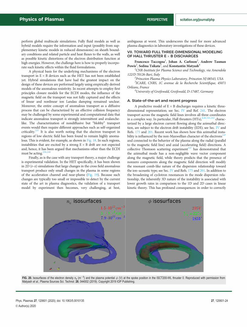
perform global multiscale simulations. Fully fluid models as well ashybrid models require the information and input (possibly from sup-plementary kinetic models in reduced dimensions) on sheath bound-ary conditions and related particle and heat fluxes to the walls, as wellas possible kinetic distortions of the electron distribution function athigh energies. However, the challenge here is how to properly incorpo-rate such kinetic effects within the fluid formulations.
A physical basis for the underlying mechanisms of the electrontransport in E�B devices such as the HET has not been establishedyet. Hybrid simulations that have had the greatest impact on thedesign of these devices are performed largely using empirically derivedmodels of the anomalous resistivity. In recent attempts to employ firstprinciples closure models for the ECDI modes, the influence of themagnetic field on the transport was not fully captured and the effectsof linear and nonlinear ion Landau damping remained unclear.Moreover, the entire concept of anomalous transport as a diffusiveprocess that can be characterized by an effective collision frequencymay be challenged by some experimental and computational data thatindicate anomalous transport is strongly intermittent and avalanche-like. The characterization of nondiffusive but “blobby” transportevents would then require different approaches such as self-organizedcriticality.237 It is also worth noting that the electron transport inregions of low electric field has been found to remain highly anoma-lous. This is evident, for example, as shown in Fig. 18. In such regions,instabilities that are excited by a strong E�B drift are not expectedand, hence, it has been argued that mechanisms other than the ECDImust be acting.236,240
Finally, as is the case with any transport theory, a major challengeis experimental validation. In the HET specifically, it has been shownin 2D (r–z) simulations that large changes in the cross field anomaloustransport produce only small changes in the plasma in some regionsof the acceleration channel and near-plume (Fig. 19). Because suchchanges are typically too small or impossible to detect by the currentstate of the art in plasma diagnostics, the validation of a transportmodel by experiment then becomes, very challenging, at best,
ambiguous at worst. This underscores the need for more advancedplasma diagnostics in laboratory investigations of these devices.
VII. TOWARD FULL THREE-DIMENSIONAL MODELINGOF HALL THRUSTER E�B DISCHARGES
Francesco Taccogna1, Johan A. Carlsson2, Andrew TasmanPowis2, Sedina Tsikata3, and Konstantin Matyash4
1CNR-Institute for Plasma Science and Technology, via Amendola122/D 70126-Bari, Italy
2Princeton Plasma Physics Laboratory, Princeton NJ 08543, USA3ICARE, CNRS, 1C avenue de la Recherche Scientifique, 45071
Orl�eans, France4University of Greifswald, Greifswald, D-17487, Germany
A. State-of-the-art and recent progress
A predictive model of E�B discharges requires a kinetic three-dimensional representation; see Sec. IV and Ref. 241. The electrontransport across the magnetic field lines involves all three coordinatesin a complex way. In particular, Hall thrusters (HTs),4,44,141,242 charac-terized by a large electron current flowing along the azimuthal direc-tion, are subject to the electron drift instability (EDI); see Sec. IV andRefs. 175 and 201. Recent work has shown how this azimuthal insta-bility is influenced by the non-Maxwellian character of the electrons147
and connected to the behavior of the plasma along the radial (parallelto the magnetic field line) and axial (accelerating field) directions. Acollective Thomson scattering experiment147 has demonstrated thatthe azimuthal mode has a non-negligible wave vector componentalong the magnetic field, while theory predicts that the presence ofnonzero components along the magnetic field direction will modifythe resonant comb-like nature of the dispersion relationship towardthe ion–acoustic type; see Sec. IV and Refs. 175 and 201. In addition tothe broadening of cyclotron resonances in the mode dispersion rela-tionship, the inherently 3D nature of the instability is associated withlower growth rates in comparison to the 1D and 2D cases in linearkinetic theory. This has profound consequences: in order to correctly
FIG. 20. Isosurfaces of the electron density ne (m�3) and the plasma potential / (V) at the spoke position in the ISCT200-WL thruster 0. Reproduced with permission from
Matyash et al., Plasma Sources Sci. Technol. 28, 044002 (2019). Copyright 2019 IOP Publishing.
Physics of Plasmas PERSPECTIVE scitation.org/journal/php
Phys. Plasmas 27, 120601 (2020); doi: 10.1063/5.0010135 27, 120601-24
VC Author(s) 2020
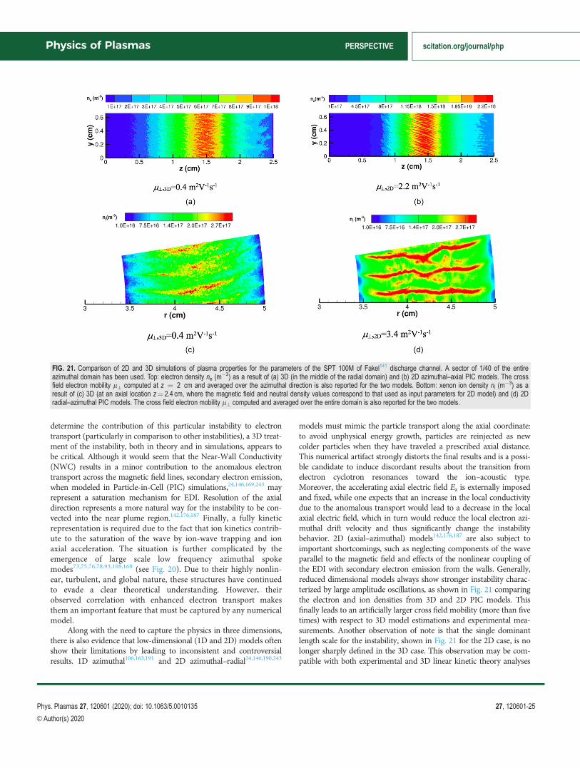
determine the contribution of this particular instability to electrontransport (particularly in comparison to other instabilities), a 3D treat-ment of the instability, both in theory and in simulations, appears tobe critical. Although it would seem that the Near-Wall Conductivity(NWC) results in a minor contribution to the anomalous electrontransport across the magnetic field lines, secondary electron emission,when modeled in Particle-in-Cell (PIC) simulations,24,146,169,243 mayrepresent a saturation mechanism for EDI. Resolution of the axialdirection represents a more natural way for the instability to be con-vected into the near plume region.142,176,187 Finally, a fully kineticrepresentation is required due to the fact that ion kinetics contrib-ute to the saturation of the wave by ion-wave trapping and ionaxial acceleration. The situation is further complicated by theemergence of large scale low frequency azimuthal spokemodes73,75,76,78,93,108,168 (see Fig. 20). Due to their highly nonlin-ear, turbulent, and global nature, these structures have continuedto evade a clear theoretical understanding. However, theirobserved correlation with enhanced electron transport makesthem an important feature that must be captured by any numericalmodel.
Along with the need to capture the physics in three dimensions,there is also evidence that low-dimensional (1D and 2D) models oftenshow their limitations by leading to inconsistent and controversialresults. 1D azimuthal106,163,191 and 2D azimuthal–radial24,146,190,243
models must mimic the particle transport along the axial coordinate:to avoid unphysical energy growth, particles are reinjected as newcolder particles when they have traveled a prescribed axial distance.This numerical artifact strongly distorts the final results and is a possi-ble candidate to induce discordant results about the transition fromelectron cyclotron resonances toward the ion–acoustic type.Moreover, the accelerating axial electric field Ez is externally imposedand fixed, while one expects that an increase in the local conductivitydue to the anomalous transport would lead to a decrease in the localaxial electric field, which in turn would reduce the local electron azi-muthal drift velocity and thus significantly change the instabilitybehavior. 2D (axial–azimuthal) models142,176,187 are also subject toimportant shortcomings, such as neglecting components of the waveparallel to the magnetic field and effects of the nonlinear coupling ofthe EDI with secondary electron emission from the walls. Generally,reduced dimensional models always show stronger instability charac-terized by large amplitude oscillations, as shown in Fig. 21 comparingthe electron and ion densities from 3D and 2D PIC models. Thisfinally leads to an artificially larger cross field mobility (more than fivetimes) with respect to 3D model estimations and experimental mea-surements. Another observation of note is that the single dominantlength scale for the instability, shown in Fig. 21 for the 2D case, is nolonger sharply defined in the 3D case. This observation may be com-patible with both experimental and 3D linear kinetic theory analyses
FIG. 21. Comparison of 2D and 3D simulations of plasma properties for the parameters of the SPT 100M of Fakel141 discharge channel. A sector of 1/40 of the entireazimuthal domain has been used. Top: electron density ne (m
�3) as a result of (a) 3D (in the middle of the radial domain) and (b) 2D azimuthal–axial PIC models. The crossfield electron mobility l? computed at z ¼ 2 cm and averaged over the azimuthal direction is also reported for the two models. Bottom: xenon ion density ni (m
�3) as aresult of (c) 3D (at an axial location z¼ 2.4 cm, where the magnetic field and neutral density values correspond to that used as input parameters for 2D model) and (d) 2Dradial–azimuthal PIC models. The cross field electron mobility l? computed and averaged over the entire domain is also reported for the two models.
Physics of Plasmas PERSPECTIVE scitation.org/journal/php
Phys. Plasmas 27, 120601 (2020); doi: 10.1063/5.0010135 27, 120601-25
VC Author(s) 2020
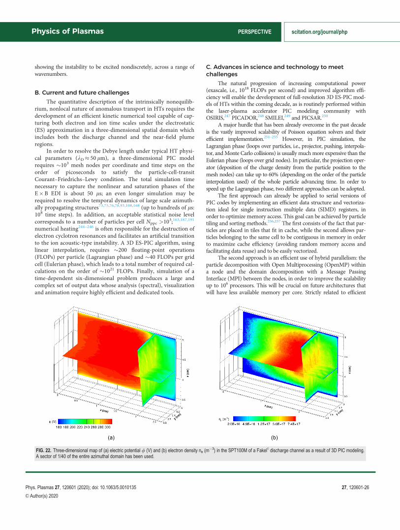
showing the instability to be excited nondiscretely, across a range ofwavenumbers.
B. Current and future challenges
The quantitative description of the intrinsically nonequilib-rium, nonlocal nature of anomalous transport in HTs requires thedevelopment of an efficient kinetic numerical tool capable of cap-turing both electron and ion time scales under the electrostatic(ES) approximation in a three-dimensional spatial domain whichincludes both the discharge channel and the near-field plumeregions.
In order to resolve the Debye length under typical HT physi-cal parameters (kD 50 lm), a three-dimensional PIC modelrequires �103 mesh nodes per coordinate and time steps on theorder of picoseconds to satisfy the particle-cell-transitCourant–Friedrichs–Lewy condition. The total simulation timenecessary to capture the nonlinear and saturation phases of theE�B EDI is about 50 ls; an even longer simulation may berequired to resolve the temporal dynamics of large scale azimuth-ally propagating structures73,75,76,78,93,108,168 (up to hundreds of ls:108 time steps). In addition, an acceptable statistical noise levelcorresponds to a number of particles per cell Nppc >10
3;163,187,191
numerical heating244–246 is often responsible for the destruction ofelectron cyclotron resonances and facilitates an artificial transitionto the ion acoustic-type instability. A 3D ES-PIC algorithm, usinglinear interpolation, requires �200 floating-point operations(FLOPs) per particle (Lagrangian phase) and �40 FLOPs per gridcell (Eulerian phase), which leads to a total number of required cal-culations on the order of �1021 FLOPs. Finally, simulation of atime-dependent six-dimensional problem produces a large andcomplex set of output data whose analysis (spectral), visualizationand animation require highly efficient and dedicated tools.
C. Advances in science and technology to meetchallenges
The natural progression of increasing computational power(exascale, i.e., 1018 FLOPs per second) and improved algorithm effi-ciency will enable the development of full-resolution 3D ES-PIC mod-els of HTs within the coming decade, as is routinely performed withinthe laser-plasma accelerator PIC modeling community withOSIRIS,247 PICADOR,248 SMILEI,249 and PICSAR.250
A major hurdle that has been already overcome in the past decadeis the vastly improved scalability of Poisson equation solvers and theirefficient implementation.251–255 However, in PIC simulation, theLagrangian phase (loops over particles, i.e., projector, pushing, interpola-tor, andMonte Carlo collisions) is usually much more expensive than theEulerian phase (loops over grid nodes). In particular, the projection oper-ator (deposition of the charge density from the particle position to themesh nodes) can take up to 60% (depending on the order of the particleinterpolation used) of the whole particle advancing time. In order tospeed up the Lagrangian phase, two different approaches can be adopted.
The first approach can already be applied to serial versions ofPIC codes by implementing an efficient data structure and vectoriza-tion ideal for single instruction multiple data (SIMD) registers, inorder to optimize memory access. This goal can be achieved by particletiling and sorting methods.256,257 The first consists of the fact that par-ticles are placed in tiles that fit in cache, while the second allows par-ticles belonging to the same cell to be contiguous in memory in orderto maximize cache efficiency (avoiding random memory access andfacilitating data reuse) and to be easily vectorized.
The second approach is an efficient use of hybrid parallelism: theparticle decomposition with Open Multiprocessing (OpenMP) withina node and the domain decomposition with a Message PassingInterface (MPI) between the nodes, in order to improve the scalabilityup to 106 processors. This will be crucial on future architectures thatwill have less available memory per core. Strictly related to efficient
FIG. 22. Three-dimensional map of (a) electric potential / (V) and (b) electron density ne (m�3) in the SPT100M of a Fakel6 discharge channel as a result of 3D PIC modeling.
A sector of 1/40 of the entire azimuthal domain has been used.
Physics of Plasmas PERSPECTIVE scitation.org/journal/php
Phys. Plasmas 27, 120601 (2020); doi: 10.1063/5.0010135 27, 120601-26
VC Author(s) 2020
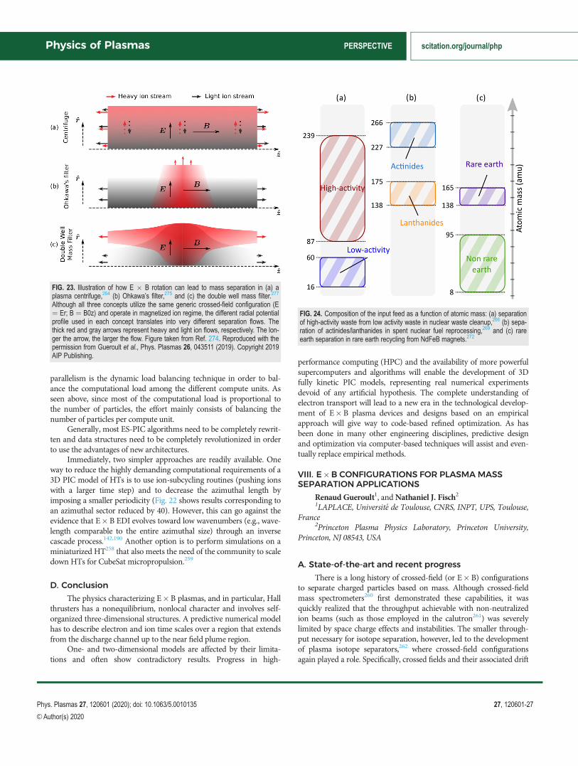
parallelism is the dynamic load balancing technique in order to bal-ance the computational load among the different compute units. Asseen above, since most of the computational load is proportional tothe number of particles, the effort mainly consists of balancing thenumber of particles per compute unit.
Generally, most ES-PIC algorithms need to be completely rewrit-ten and data structures need to be completely revolutionized in orderto use the advantages of new architectures.
Immediately, two simpler approaches are readily available. Oneway to reduce the highly demanding computational requirements of a3D PIC model of HTs is to use ion-subcycling routines (pushing ionswith a larger time step) and to decrease the azimuthal length byimposing a smaller periodicity (Fig. 22 shows results corresponding toan azimuthal sector reduced by 40). However, this can go against theevidence that E�B EDI evolves toward low wavenumbers (e.g., wave-length comparable to the entire azimuthal size) through an inversecascade process.142,190 Another option is to perform simulations on aminiaturized HT258 that also meets the need of the community to scaledown HTs for CubeSat micropropulsion.259
D. Conclusion
The physics characterizing E�B plasmas, and in particular, Hallthrusters has a nonequilibrium, nonlocal character and involves self-organized three-dimensional structures. A predictive numerical modelhas to describe electron and ion time scales over a region that extendsfrom the discharge channel up to the near field plume region.
One- and two-dimensional models are affected by their limita-tions and often show contradictory results. Progress in high-
performance computing (HPC) and the availability of more powerfulsupercomputers and algorithms will enable the development of 3Dfully kinetic PIC models, representing real numerical experimentsdevoid of any artificial hypothesis. The complete understanding ofelectron transport will lead to a new era in the technological develop-ment of E�B plasma devices and designs based on an empiricalapproach will give way to code-based refined optimization. As hasbeen done in many other engineering disciplines, predictive designand optimization via computer-based techniques will assist and even-tually replace empirical methods.
VIII. E�B CONFIGURATIONS FOR PLASMA MASSSEPARATION APPLICATIONS
Renaud Gueroult1, andNathaniel J. Fisch21LAPLACE, Universit�e de Toulouse, CNRS, INPT, UPS, Toulouse,
France2Princeton Plasma Physics Laboratory, Princeton University,
Princeton, NJ 08543, USA
A. State-of-the-art and recent progress
There is a long history of crossed-field (or E�B) configurationsto separate charged particles based on mass. Although crossed-fieldmass spectrometers260 first demonstrated these capabilities, it wasquickly realized that the throughput achievable with non-neutralizedion beams (such as those employed in the calutron261) was severelylimited by space charge effects and instabilities. The smaller through-put necessary for isotope separation, however, led to the developmentof plasma isotope separators,262 where crossed-field configurationsagain played a role. Specifically, crossed fields and their associated drift
FIG. 24. Composition of the input feed as a function of atomic mass: (a) separationof high-activity waste from low activity waste in nuclear waste cleanup,266 (b) sepa-ration of actinides/lanthanides in spent nuclear fuel reprocessing,269 and (c) rareearth separation in rare earth recycling from NdFeB magnets.272
FIG. 23. Illustration of how E � B rotation can lead to mass separation in (a) aplasma centrifuge,264 (b) Ohkawa’s filter,275 and (c) the double well mass filter.277
Although all three concepts utilize the same generic crossed-field configuration (E¼ Er; B ¼ B0z) and operate in magnetized ion regime, the different radial potentialprofile used in each concept translates into very different separation flows. Thethick red and gray arrows represent heavy and light ion flows, respectively. The lon-ger the arrow, the larger the flow. Figure taken from Ref. 274. Reproduced with thepermission from Gueroult et al., Phys. Plasmas 26, 043511 (2019). Copyright 2019AIP Publishing.
Physics of Plasmas PERSPECTIVE scitation.org/journal/php
Phys. Plasmas 27, 120601 (2020); doi: 10.1063/5.0010135 27, 120601-27
VC Author(s) 2020

were used to produce plasma rotation263 in plasma centrifuges,264,265
as illustrated in Fig. 23(a).More recently, there has been a growing recognition that elemen-
tal separation based on mass offers highly promising conceptual solu-tions to several societal high-impact applications, including nuclearwaste cleanup,266 spent nuclear fuel (SNF) reprocessing,267–271 andrare earth element (REE) recycling.272 For these applications, conven-tional chemical separation techniques are inefficient since one needsto separate feeds of varying chemical composition (REE recycling andnuclear waste clean-up) or elements with similar chemical properties(SNF reprocessing). Further to these inefficiencies, chemical separationoften leads to the production of secondary, and possibly hazardous,waste. On the other hand, as illustrated in Fig. 24, it happens that thefeed conveniently splits into two groups based on atomic mass, sup-porting the interest of elemental mass separation. Compared to chemi-cal techniques, another anticipated advantage of plasma separation liesin its much smaller environmental footprint. Thanks to these charac-teristics, plasma separation may be economically competitive for cer-tain applications,266,272 particularly considering that energy costs fromsolar may become significantly cheaper. However, the separationneeds of these new applications differ significantly from those ofisotope separation, thereby offering new challenges.273
B. Current and future challenges
To be useful for these new applications, plasma separators notonly have to separate elements with large mass differences (�tens ofamu), but also, and importantly, to operate at high throughput(�104 kg/yr). It is also advantageous if the separation methods do notperform well on isotopes to lessen proliferation risks. Since these capa-bilities are well beyond those accessible to isotope separators, newplasma mass filter concepts are called for.
Here, also, the rich physics of crossed-field configurations offersmany opportunities and various conceptual solutions have been sug-gested in the last decade.267,275 In regimes where both ions and elec-trons are magnetized, crossed-field configurations can be designed todrive rotation. By exploiting rotation in novel ways, conceptual solu-tions for mass separation can then be found beyond plasma centri-fuges275–277 as shown in Figs. 23(b) and 23(c). Alternatively, inregimes where ions are unmagnetized, but electrons are magnetized,crossed-field configurations can in principle be designed to separatethe ions of a rotating annular ion beam,278,279 or to further exploit dif-ferences in gyroradius.280
In all of these concepts, large mass differences are advantageous,and, in view of proliferation risks, usefully necessary. On the otherhand, high-throughput operation has been shown to bring a new setof physics and engineering challenges,281 which are yet to beaddressed.
C. Advances in science and technology to meetchallenges
Upstream of the elemental separation stage discussed above, oneneeds to consider how to produce the high-density plasma requiredfor separation from solids or liquid input streams. Many challengesare found at this stage. First, how to feed into a vacuum chamber andthen ionize, grams of material per second while minimizing energycost? Laser evaporation of solid targets and injection of micrometer
size powder have been suggested so far, but this question ought to beaddressed in detail. Another constraint on the plasma source is theneed to maximize charge uniformity. Indeed, since separation oftenresults from differences in the ion charge to mass ratio Ze/mi and notin the ion mass alone, effective separation requires producing a plasmawith Z as close as possible to homogeneous and uniform across ionspecies. Furthermore, low Z materials are to be preferred to minimizeradiation losses, which translates into electron temperature Te of atmost a few eV for most atoms. Finally, related to this challenge is theopen question of how molecules will impact separation. While signifi-cant molecular ion components are expected due to the low Te, thedetailed composition of plasmas formed from complex mixtures is farfrom understood and so is the dynamics of these compounds.In addition, cross section data for molecular processes is likely notreadily available for some of the uncommon elements (e.g., the sesqui-oxides) found in these applications.
The separation stage also offers challenges. Assuming a singlyionized atomic plasma could be produced, separation in crossed-fieldconcepts is conditioned upon externally applying a specific potentialprofile in the direction perpendicular to the magnetic field.Fundamentally, the ability to support this perpendicular potential pro-file depends on the ratio of perpendicular to parallel conductivityr?/rk.
282 However, many different drivingmechanisms (e.g., collisionswith neutral, instabilities and turbulence,283 magnetic fluctuations,284
ion viscosity285) are known to contribute to r? depending on theoperating plasma conditions, and new driving mechanisms continueto be uncovered.286,287 Demonstrating the practicality of crossed-fieldmass filter concepts hence hinges on a comprehensive understandingof perpendicular conductivity, which we believe will be best obtainedby a combination of modeling and experiments.274,288 Another out-standing issue in the presence of neutrals is the possible upper limit seton the rotation speed by the critical ionization velocityphenomenon.289
D. Conclusion
The challenges briefly discussed above are only a small subset ofthe many open questions that remain to be addressed to demonstratehigh-throughput plasma separation as a practical process (seeRefs. 267 and 281 for a detailed discussion). Yet, we believe that thepromise plasma separation holds for many outstanding societalchallenges is a compelling motivation to tackle these questions. In addi-tion, progress toward many of these scientific and engineering goalswill benefit applications beyond plasma separation. For instance, thebasic question of perpendicular conductivity in a magnetized plasma isalso central to recently proposed promising schemes for magnetic con-finement fusion.290,291 Understanding how perpendicular electric fieldscan be externally applied will more generally benefit the large numberof applications making use of cross field configurations.
IX. VALIDATION AND VERIFICATION PROCEDURESFOR DISCHARGE MODELING
Anne Bourdon1, Pascal Chabert1, Alexander V. Khrabrov2,Andrew Tasman Powis2, Ioannis G. Mikellides3, and IgorD. Kaganovich2
1Laboratoire de Physique des Plasmas, CNRS, Ecole Polytechnique,Sorbonne Universit�e, 91120 Palaiseau, France
2Princeton Plasma Physics Laboratory, Princeton NJ 08543, USA
Physics of Plasmas PERSPECTIVE scitation.org/journal/php
Phys. Plasmas 27, 120601 (2020); doi: 10.1063/5.0010135 27, 120601-28
VC Author(s) 2020

3Jet Propulsion Laboratory, California Institute of Technology,Pasadena, CA, 91109, USA
A. State-of-the-art and recent progress
The ultimate objective for developing computer simulations ofcomplex physical systems is to use these simulations as a predictivetool for science and engineering design. This would reduce the numberof costly experiments required for the development of applicationsinvolving low-temperature plasmas. For example, currently, the designand development of electric thrusters are semi-empirical with long (onthe order of 10 000h) and expensive lifetime tests. Applications thatemploy low-temperature plasmas generally involve complex multiphy-sics and multiscale processes. Developing accurate and predictive sim-ulation tools remains an active area of research. Critical to these goalsis the need to verify and validate codes used for the predictive model-ing of low-temperature plasmas.
In other fields, rigorous verification and validation (V&V) proce-dures have been implemented for decades. Computational fluiddynamics (CFD) codes, which are used for the design of commercialairplanes, cooling systems, and to simulate wind loads around build-ings and bridges apply tests of code reliability by regulation to adhereto professional engineering standards.292,293 Prominent engineeringjournals require V&V testing as part of their editorial policy beforeacceptance of papers.294
In order to develop predictive capabilities for low-temperatureplasmas, several necessary steps have to be performed.
• Develop a minimum complexity self-consistent mathematicalmodel that describes the effects to be predicted.
• Develop numerical codes and check these codes for bugs bybenchmarking with other codes, and with analytical ormanufacturing solutions, and verify that convergence is achieved.
• Assemble a reliable set of atomistic physics and plasma–surfaceinteraction data required for modeling.
• Perform validation tests of the assumptions and simplificationsof the model by comparing simulation results with available ordedicated experiments capable of exploring a wide range ofparameters. The comparisons must be sufficiently comprehen-sive296,297 in order to avoid the bias which may occur when“measurements data and modeling results agree if they are per-formed in the same Lab” and because a narrow set of measure-ments data can be always matched by variation of adjustableparameters available in the models.
Code verification298 is used to assess the numerical accuracy of amathematical model. The first test should include convergence testswith number of grid points, values of time steps for fluid, hybrid andparticle-in-cell codes, and number of particles for particle-in-cell andhybrid codes. Note that some of the studies, for example the numberof particles in particle-in-cell (PIC) codes, are challenging due to slowconvergence, see, e.g., Ref. 295. Proving the convergence of a solvercan be accomplished through comparison with simple limiting testcases or analytical solutions. Another way to verify the code is to usemanufacturing solutions, see, e.g., Ref. 295.
Code validation proves the predictive capabilities of the devel-oped model by comparing simulation results with experimentaldata.298 This is usually more challenging and demanding because itrequires a well-organized systematic campaign of combined
experimental and numerical studies in order to convincingly demon-strate validation.296,297
An early example of such an effort for low-temperature plasmasis the work of Surendra299 for a capacitively coupled radio frequencydischarge, in which results from twelve different codes (including fourparticle-in-cell codes) were compared with each other (benchmarking)and with experimental data (validation). At the end of the 1990s, astandardized RF discharge experiment—a so-called GEC referencecell301—was also specifically designed for validation and is still used asshown in the recent study performed in Ref. 302. Recently, there havebeen different works on the benchmarking of codes. In particular,Turner et al.300 performed a parametric study of several 1D particle-in-cell codes for verification of the Poisson solver, the particle pusher,the wall boundary conditions and the ionization, andMonte Carlo col-lision modules. The comparison of the codes was performed until anerror of less than 1% was obtained. Therefore, the results of thisbenchmark can be considered as a reference solution for other 1D PICcodes. An international effort is under way to preform 2D benchmarksfor (nonmagnetized) low-pressure low-temperature plasmas.303
Recently, there has also been a renewed interest to carry out studies onplasma sheaths in low-pressure low-temperature plasmas and to usePIC simulations to guide the development of theoretical models.304
The benchmarking of fluid codes could be more involved thanthat of PIC codes. Indeed, a large variety of fluid models are used,ranging from drift-diffusion models to those which maintain a largernumber of moments for fluid closures (13 and above). Furthermore,there is a large variety of numerical schemes used to solve the set offluid equations. For example, six fluid simulation codes were recentlybenchmarked for simulation of positive streamers at atmospheric pres-sure.305 Three test cases of increasing complexity have been studied. Areasonable agreement between the results of the different codes hasbeen obtained, also showing the difficulty to of obtaining a referencesolution under given conditions.
For low-pressure low-temperature magnetized plasmas, of partic-ular interest for electric propulsion or magnetrons, a significant inter-national effort is currently underway to benchmark PIC and fluidcodes on test cases306 corresponding to typical conditions of Hallthrusters. The problem has, however, been sufficiently simplified forease of benchmarking. The first results obtained by different interna-tional groups on the three test cases have been presented at the E�Bworkshop organized at Princeton in November 2018.307 In particular,the most significant effort has been placed on the 2D test-case dedi-cated to the simulation of microinstabilities induced by the large E�Belectron drift in the acceleration zone of a Hall thruster. The test-caseis two-dimensional in the axial–azimuthal direction, close to that pro-posed in Ref. 187. Seven international groups have compared theirindependently developed PIC code results for this 2D test-case andobtained good agreement within 5% difference between all the codes;the results of this study are published recently in Ref. 204. Therefore,these results can be considered as a reference solution for other PICcodes.
The next step is the validation of codes by comparison withexperiments, which is usually an interesting but long iterative processbetween experiments and simulations. Two examples are given here.
The first one is related to the work of Carlsson et al.308 whichalso benchmarked two different PIC codes and validated them againsta well-diagnosed glow discharge experiment.309 The DC glow
Physics of Plasmas PERSPECTIVE scitation.org/journal/php
Phys. Plasmas 27, 120601 (2020); doi: 10.1063/5.0010135 27, 120601-29
VC Author(s) 2020

discharge represents a challenging test for simulations, even in onedimension. The model must correctly handle the electrons within awide range of energies, namely from several hundred eV in the cath-ode fall to a fraction of an eV for those trapped in the negative glow.For the former group, one has to correctly treat anisotropic scatteringin electron-neutral collisions (in a way still suitable for the MCapproach),310 and the Coulomb collisions between the two groupsneed to be properly reproduced in order to maintain the energy bal-ance in the negative glow. An accurate model for charge exchangecross sections is also needed,311,312 to obtain the correct ion density
in the cathode fall as well as ambipolar diffusion in the plasma.Furthermore, the Debye scale for cold electrons must be resolved,to simulate the plasma–cathode fall boundary and the anodesheath. The experiment by Den Hartog et al.309 provides spatiallyresolved measurements of the electric field in the cathode fall, withdiagnostics of plasma density and electron temperature in the neg-ative glow, for several values of discharge current and correspond-ing potential. Carlsson et al. simulated two of those cases,reporting good agreement in terms of the spatial structure andphysical parameters of the discharge.
FIG. 25. Top left: comparison of plasma measurements and simulations along the channel centerline (CL) of an unshielded 6-kW laboratory Hall thruster,220 with z denotingthe distance from the anode and L is the length of the acceleration channel. The differences between simulations and measurements revealed that plasma-perturbing diagnos-tics (like injected probes) must be avoided in the validation of Hall thruster codes.220,317 Reproduced with permission from I. G. Mikellides and A. L. Ortega, Plasma SourcesSci. Technol. 28, 075001 (2019). Copyright 2019 IOP Publishing. Top right: comparison of plasma measurements and simulations along the channel CL of a 4.5-kW SPT-140.These thrusters will enable NASA’s Psyche mission the first to use this technology beyond lunar orbit. The code validation effort reduced margins for the mission and shednew insight into the effects of facility backpressure on Hall thrusters operating with external cathodes.318,319 Reproduced with permission from Lopez Ortega et al., PlasmaSources Sci. Technol. 29, 035011 (2020). Copyright 2020 IOP Publishing. Bottom left: comparison of the ion velocity fields from simulations (black traces) and Laser-InducedFluorescence (LIF) measurements (red traces) in the Magnetically Shielded Miniature Hall Thruster (MaSMi) at 1 kW.320 Reproduced with permission from Lopez Ortega et al.,in 36th International Electric Propulsion Conference, IEPC-2019-281, Vienna, Austria, September (2019). Copyright 2019 International Conference on Electric Propulsion.Bottom right: comparison of computed and measured erosion rates along a molybdenum (Mo) cover of the inner magnetic pole in a magnetically shielded 6-kW laboratory Hallthruster.321 The validation effort explained and quantified the source of the pole cover erosion observed during wear tests322 of one of the first magnetically shielded Hall thrust-ers. The simulations used three ion-fluid (iF) populations and three ion charge (iC) states; r is the radial distance from the thruster CL and Rinnerpole is the radius of the polecover. Reproduced with the permission from J. Appl. Phys. 125, 033302 (2019). Copyright 2019 AIP Publishing.
Physics of Plasmas PERSPECTIVE scitation.org/journal/php
Phys. Plasmas 27, 120601 (2020); doi: 10.1063/5.0010135 27, 120601-30
VC Author(s) 2020

The second example is related to the effort to validate fluid-basedsolvers for low-temperature plasma discharges at the Jet PropulsionLaboratory, an effort that started there almost two decades ago.The long-standing code development and validation effort began withOrCa2D, a 2D axisymmetric fluid solver of the partially ionized gas inhollow cathode discharges,153,313,314 and benefited immensely from avery close collaboration between experimentalists and theorists. Afterseveral years of code validation with plasma measurements, OrCa2Dthen served as the framework for the development of a new code forHall thruster simulations. Dubbed Hall2De, the code was the first tosolve the fluid conservation laws for ions and electrons in these deviceson a magnetic-field-aligned-mesh, in a 2D axisymmetric (r–z)plane.214 To reduce errors associated with the large collisional relaxa-tion times of ions in the near-plume region, the code also employed amultifluid algorithm315,316 that allows for different ion populations inup to three distinct ion-energy bins. Also, up to triply charged ions canbe included for each of the ion fluids yielding a total of nine ionmomentum and nine ion continuity equations. Though much pro-gress has been made in the last decade on the anomalous electrontransport known to exist in these devices, a physical basis for theunderlying mechanisms that drive it has not been established yet.Hence, in the absence of a validated fluid closure model, generalizedOhm’s law in Hall2De employs a multivariable model of the anoma-lous collision frequency that is combined with detailed plasma mea-surements to obtain a near-continuous, empirically derived, piecewisespatial variation of the frequency everywhere in the device.220 Thecombination of simulations and extensive measurements, in a varietyof different thrusters and operating conditions, has yielded some ofthe closest agreements we have achieved with plasma and wear mea-surements so far. A few representative examples are provided inFig. 25. Persistent efforts to validate codes like Hall2De has allowedsome of codes to directly support thruster development and life quali-fication programs for space flight and identify new needs for labora-tory diagnostics while providing critical insight into the physics ofthese devices (Fig. 25).
B. Current and future challenges
Recently, there has been a renewed interest in the verificationof codes through benchmarking. For low-temperature partiallymagnetized plasmas, most significant results have been obtainedon 2D PIC codes but on a limited number of test-cases. Currently,there is a need to work on the verification of fluid codes for low-temperature magnetized plasmas. It is important to emphasize thatthe definition of the test cases is a significant part of the problem.Indeed, it is important to develop a comprehensive set of test casesto provide benchmarking of codes for the regimes of interest thatsufficiently characterize the relevant physics that are important forthe studied plasmas. For low-temperature magnetized plasmasthese are: anomalous transport, low-frequency oscillations such asbreathing modes and plasma spokes, see Secs. II–VI. A detaileddescription of validation and benchmark test-cases will be the sub-ject of future dedicated E�B workshops and the “Frontiers inLow-temperature Plasma Simulations” workshop. These work-shops will facilitate discussions and idea exchanges between inter-national groups to better define, discuss, and compare results.
For validation of models and codes, a comprehensive set of mea-surements is needed. This is challenging for a compact and energetic
Hall thrusters where probes can strongly perturb plasma and it is diffi-cult to measure plasma parameters in the ionization and accelerationzones. A possible approach is to validate codes on specially designedplasma systems that allow for easier access for diagnostics, similar tothe GEC cell for RF discharge.301 An example of such a study forE�B discharges is the Penning discharge.92 For Hall thrusters, possi-bly a scaled-up Hall thruster with improved access is desired for accu-rate validation of simulation results. Another approach is to use awall-less Hall thruster where the acceleration zone is outside thethruster channel.162 Comprehensive measurements by several diag-nostics probes, LIF and CTS, see Sec. III, is also needed for completecharacterization of anomalous transport and turbulent oscillationspectra.
C. Advances in science and technology to meetchallenges
Currently most simulations are carried out in 2D and the numberof 3D simulations remains limited. The development of computingresources and high-performance computing already enables us tocarry out parametric studies in 2D which were out of reach 10 yearsago. In the coming years, with the ongoing development of computingresources and the interest in small-size thrusters, the number of 3Dsimulations of thrusters without scaling of geometry to speedup simu-lations will increase, which will also require the need to carefully define3D benchmarks. It will also be a very interesting opportunity to carryout parametric studies that are currently still out of reach in particular,to study the effects of plasma–wall interaction and instabilities. Newmeans of communication, systems of code version control, means ofdata exchanges, and ease the sharing of results and discussions willgreatly enable V&V activities of the future.
The development of more refined time and space-resolvedmeasurement techniques is also expected. In particular as described inSec. III, there are still too few measurements of high-frequency oscilla-tions in low-temperature partially magnetized plasmas.
D. Conclusions
Currently, the design and development of electric thrustersremains semi-empirical with long and expensive lifetime tests. Inthe future, with the use of electric propulsion for constellations ofsmall satellites in low-earth orbit or high-power electric propulsionsystems for full orbit raising and orbit transfer, there is a need toreduce the time to design and to develop new generations of elec-tric thrusters. This will be achieved only by combining moreclosely engineering experiments, measurement campaigns in aca-demic experiments, and modeling and simulations. The recentdevelopments of computing resources and high-performance com-puting already enables us to carry out parametric studies that wereout of reach only a few years ago. The most significant difficulty isprobably to develop a 3D hybrid and full PIC codes that can beused for engineering design, with a reasonable computing time andwhich would be validated on a comprehensive set of test cases forthe regimes of interest for electric propulsion applications: anoma-lous transport, breathing oscillations, and spokes. Recent efforts inthe community on the definition of test cases and benchmarkingand validation of codes should be pursued.
Physics of Plasmas PERSPECTIVE scitation.org/journal/php
Phys. Plasmas 27, 120601 (2020); doi: 10.1063/5.0010135 27, 120601-31
VC Author(s) 2020
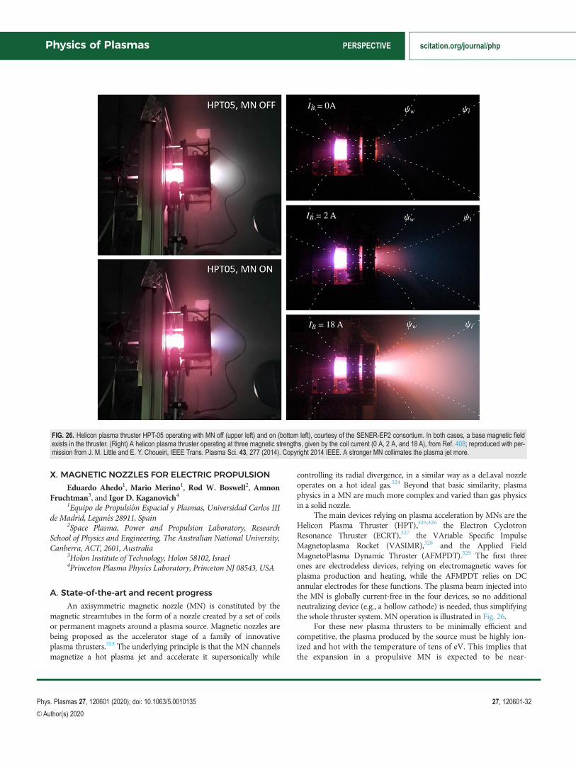
X. MAGNETIC NOZZLES FOR ELECTRIC PROPULSION
Eduardo Ahedo1, Mario Merino1, Rod W. Boswell2, AmnonFruchtman3, and Igor D. Kaganovich4
1Equipo de Propulsi�on Espacial y Plasmas, Universidad Carlos IIIde Madrid, Legan�es 28911, Spain
2Space Plasma, Power and Propulsion Laboratory, ResearchSchool of Physics and Engineering, The Australian National University,Canberra, ACT, 2601, Australia
3Holon Institute of Technology, Holon 58102, Israel4Princeton Plasma Physics Laboratory, Princeton NJ 08543, USA
A. State-of-the-art and recent progress
An axisymmetric magnetic nozzle (MN) is constituted by themagnetic streamtubes in the form of a nozzle created by a set of coilsor permanent magnets around a plasma source. Magnetic nozzles arebeing proposed as the accelerator stage of a family of innovativeplasma thrusters.323 The underlying principle is that the MN channelsmagnetize a hot plasma jet and accelerate it supersonically while
controlling its radial divergence, in a similar way as a deLaval nozzleoperates on a hot ideal gas.324 Beyond that basic similarity, plasmaphysics in a MN are much more complex and varied than gas physicsin a solid nozzle.
The main devices relying on plasma acceleration by MNs are theHelicon Plasma Thruster (HPT),325,326 the Electron CyclotronResonance Thruster (ECRT),327 the VAriable Specific ImpulseMagnetoplasma Rocket (VASIMR),328 and the Applied FieldMagnetoPlasma Dynamic Thruster (AFMPDT).329 The first threeones are electrodeless devices, relying on electromagnetic waves forplasma production and heating, while the AFMPDT relies on DCannular electrodes for these functions. The plasma beam injected intothe MN is globally current-free in the four devices, so no additionalneutralizing device (e.g., a hollow cathode) is needed, thus simplifyingthe whole thruster system. MN operation is illustrated in Fig. 26.
For these new plasma thrusters to be minimally efficient andcompetitive, the plasma produced by the source must be highly ion-ized and hot with the temperature of tens of eV. This implies thatthe expansion in a propulsive MN is expected to be near-
FIG. 26. Helicon plasma thruster HPT-05 operating with MN off (upper left) and on (bottom left), courtesy of the SENER-EP2 consortium. In both cases, a base magnetic fieldexists in the thruster. (Right) A helicon plasma thruster operating at three magnetic strengths, given by the coil current (0 A, 2 A, and 18 A), from Ref. 408; reproduced with per-mission from J. M. Little and E. Y. Choueiri, IEEE Trans. Plasma Sci. 43, 277 (2014). Copyright 2014 IEEE. A stronger MN collimates the plasma jet more.
Physics of Plasmas PERSPECTIVE scitation.org/journal/php
Phys. Plasmas 27, 120601 (2020); doi: 10.1063/5.0010135 27, 120601-32
VC Author(s) 2020

collisionless, which is not the case in other applications (such asmaterial processing331 or plasma wind tunnels330). Theoreticalefforts to understand these propulsive magnetic nozzles involveboth fluid and kinetic models. Some of these models admit semi-analytical solutions, which have been essential to understand theMN physics explained below.
In particular, two-dimensional (2D) axisymmetric fluid modelshave shown to be a powerful tool to understand the main phenomenain the MN.334 However, the closure of a fluid model for a collisionlessplasma (at the heat flux level, for instance) is an open, elusive problem.One-dimensional (1D), stationary, kinetic models of a paraxial MNbased on solving the Vlasov equation335,336 complement fluid modelswell. In particular, kinetic models have allowed analyzing the down-stream ion and electron heat fluxes and the response to non-
Maxwellian features of the ion and electron velocity distribution func-tions (VDFs).
From the energy point of view, plasma thrusters relying on a pro-pulsive MN, are electrothermal, the MN converting the plasma inter-nal energy into axially directed (ion) energy. However, these thrustersdiffer in the way the internal energy is stored in the plasma: as electronthermal energy on the HPT and ECRT, mostly as thermal ion energyon the VASIMR, and as a mix of energy types (electron thermal, ionswirling) on the AFMPDT.337 Besides, internal energy (i.e., tempera-ture) is anisotropic in the cases of the ECRT and the VASIMR. Hence,the energy conversion mechanism of the MN from an internal to axi-ally directed one is device-dependent. When energy must be trans-ferred from electrons to ions, the conversion agent is the ambipolarelectric field,338,339 while the collective mechanism is mainly gas-
FIG. 27. Detachment of ion streamlines in a MN. The left and center plots show simulation results for moderate and high magnetic field strength in a helicon plasma thruster-like device. A higher magnetic field strength results in ions detaching further downstream and acquiring a larger divergence angle. From Ref. 341. Reproduced with permissionfrom Plasma Sources Sci. Technol. 23, 032001 (2014). Copyright 2014 IOP Publishing. The figure to the right shows the experimentally measured ion streamline detachmentin a VASIMR prototype. From Ref. 328. Reproduced with permission from C. S. Olsen et al., “Investigation of plasma detachment from a magnetic nozzle in the plume of theVX-200 magnetoplasma thruster,” IEEE Trans. Plasma Sci. 43, 252 (2015) Copyright 2015 IEEE.
FIG. 28. (Left): schematic of the azimuthal currents in the magnetic coils and in the plasma of a divergent MN. Paramagnetic azimuthal currents rotate in the same direction ascoil currents and attract each other, producing magnetic drag (negative magnetic thrust). Ions develop a small paramagnetic current in, e.g., HPTs and ECRTs. Diamagneticazimuthal currents rotate in the opposite direction as coil currents and repel each other, producing magnetic thrust. Electron azimuthal current is diamagnetic and dominates inthe plasma. Additionally, the plasma creates pressure thrust on the chamber walls. (Right): experimentally measured magnetic thrust (open blue circles) and total thrust (openred squares) from Ref. 345 in a helicon plasma thruster. Reproduced with permission from Takahashi et al., Phys. Rev. Lett. 107, 235001 (2011). Copyright 2011 AmericanPhysical Society. The solid blue circles and solid red squares correspond to the expected values from a model. The black triangles represent the modeled pressure thrust.
Physics of Plasmas PERSPECTIVE scitation.org/journal/php
Phys. Plasmas 27, 120601 (2020); doi: 10.1063/5.0010135 27, 120601-33
VC Author(s) 2020

dynamical when the conversion is from thermal to axially directed ionenergy.328
Magnetic channeling of the plasma beam is based mainly on elec-tron magnetization, which requires a large Hall parameter (i.e., theratio between the electron gyrofrequency and the collision frequency)and a small electron gyroradius (compared to the nozzle cross sec-tion).323 In HPTs, ECRTs, ECRTs, and (low power) AFMPDTs, withmagnetic fields in the 0.01–0.1 Tesla range, ions are weakly magne-tized and are bound to highly magnetized electrons through the ambi-polar electric field. In the VASIMR, with magnetic fields above 1 Tand using light propellants, ions are highly magnetized and possessthermal energy and some of the MN phenomena described below(focused on hot electrons) can differ somewhat.
Ion and electron dynamics along the divergent MN lines are verydifferent. In the collisionless scenario, both species are coupledthrough the ambipolar electric field, which develops to keep chargequasineutrality. The resulting electrostatic potential decreases bothradially and axially from the MN throat, in order to confine most ofthe electron population while it accelerates ions freely downstream.334
The total fall of the electric potential along the MN is self-adjusted tomaintain the plasma globally current-free and determines the ultimatevelocity of ions. The heavier the propellant is, the higher that totalpotential fall is, following the same principle as in a Debye sheath nextto a nonconducting wall.336
Ion dynamics are simpler. As ions expand downstream of theMN, the ion becomes more energetic and less magnetized, while theambipolar electric field becomes weaker. Thus, when the local iongyroradius (based on its macroscopic velocity) is not smaller than theMN cross section radius, the electric field is unable to bind the ionstream surfaces perfectly to the magnetic and electron ones and theion stream surfaces detach progressively and inwards from magneticsurfaces, becoming conic eventually.341 The lower the angle of thiscone, the lower is the plasma beam divergence. This MN detachmentmechanism, illustrated in Fig. 27 and based on ion demagnetization, issupported experimentally.328,342
Electrons, on the contrary, can remain magnetized for a verylong distance. Collisions, electron inertia, and instabilities are diffusionprocesses favoring outward electron detachment, which in fact is detri-mental for beam collimation.343,344 Nonetheless, demagnetization anddetachment of the confined cloud of electrons does not seem to affectmuch the far-downstream properties of the plasma beam.
Magnetic nozzles have no walls, thus avoiding thermal loadsand erosion issues. But neither is there the mechanical thrust gainof a solid nozzle. Instead, the divergent MN is an electromagneticdevice from the momentum point of view: magnetic thrust isachieved thanks to the diamagnetic drift developing on elec-trons.343,345–348 These drifts form azimuthal current loops, of dia-magnetic character, which induce a magnetic field acting on thethruster coils.349,404,405 This coil/plasma configuration is equiva-lent to the basic setup of two wire loops with counterstreamingelectric currents (of different magnitude), which repel each other,as shown in Fig. 28. In the moderate plasma-beta case (i.e., similarthermal and magnetic pressures), the induced magnetic fieldmodifies the shape of the MN, increasing its divergence.350 Ionazimuthal currents are created too, but (with possible VASIMR’sexception) these are paramagnetic and decelerate the plasmabeam.343,351 This paramagnetic effect is stronger when the ions
become more magnetized and it has been observed in the propa-gation of an ion beam along a straight magnetic field.352 Sincehigh ion magnetization is negative in terms of paramagneticeffects and detachment, there must exist an intermediate mag-netic field strength optimizing the propulsive features of a MN.406
While a current-free beam assures that r �~j ¼ 0; with~j beingthe electric current density, it does not assure local current ambipolar-ity, i.e.,~j ¼~0:366 Indeed, the ion detachment implies that local currentambipolarity is not satisfied and small longitudinal (i.e., in the meri-dian plane) current loops develop, which nonetheless are severalorders of magnitude smaller than the azimuthal electric currents.344
B. Current and future challenges
While the above MN physics can be considered to be reasonablyestablished and understood, there are many other aspects requiringfurther investigation and definitely more experimental validation ofMN physics.
The evolution of the electron velocity distribution function(VDF) in the divergent MN is a principal challenge, due to the rele-vance of the VDF and the thermal electron energy on the beam expan-sion in the MN. Paraxial kinetic models have identified regions inphase space where doubly trapped electrons, bouncing back and forthalong magnetic lines in a limited region isolated from both upstreamand downstream sources, can exist.335,336 These regions would becomepopulated during the transient period of formation of the MN and bysporadic collisions.367,368 If the repopulation is large, doubly trappedelectrons can be the main electron subpopulation in certain MNregions and shape the plasma expansion there.
Doubly trapped electrons are confined in a limited region by thecombined and opposite effects of the magnetic mirror and the electro-static barrier.336 Interestingly, similar doubly trapped electrons are alsofound in other collisionless plasmas. A well-known case is theLangmuir probe, where the role of the magnetic moment invariant issubstituted by the angular momentum one.369 A closely related case isa slowly divergent, unmagnetized, plasma plume where the magneticmoment is replaced by the radial-action integral invariant.370
Temperature anisotropy is a relevant feature in most cases and areal challenge for diagnostics too. The problem has several faces. First,there is the case of the expansion of an isotropic (e.g., Maxwellian)VDF where recent analyses show that the electron population developsonly a small temperature anisotropy along the nozzle and, as a conse-quence, the collective magnetic mirror effect is weak on it.336 On thecontrary, ions, if hot and magnetized, develop a large temperatureanisotropy. Both nonintuitive conclusions deserve experimental con-firmation. Second, there is the case of the expansion of a Maxwellianplasma with a certain amount of suprathermal electrons, a casereported in some HPT experiments and leading to the possible forma-tion of current-free double layers.371–373 And third, there is the evolu-tion of the anisotropic VDFs of (a) energetic electrons in the ECRTcase and (b) energetic ions in the VASIMR case, and both of themhave not been well characterized experimentally yet.
The evolution of the electron VDF is closely related to the much-discussed problem of the nature of the observed beam cooling alongthe MN. Experimental data usually assess the electron temperaturedecrease relative to the density one through an empirical polytropiccoefficient, c. Values in the range c ¼ 1.15–1.25 seem to be com-mon,327,374,375,407 but larger c values, corresponding to adiabatic
Physics of Plasmas PERSPECTIVE scitation.org/journal/php
Phys. Plasmas 27, 120601 (2020); doi: 10.1063/5.0010135 27, 120601-34
VC Author(s) 2020

behaviors, have been reported too.376 Recent experiments capable ofcharacterizing the VDFs of the different electron subpopulations sug-gest that free electrons (i.e., those flowing downstream with the ions)tend to be adiabatic (i.e., c ¼ 5/3 in three dimensions), while confinedones (included double-trapped) are isothermal.377,378 Further evidenceis needed. Interestingly, electron cooling in unmagnetized plumes fitsalso with low values of c, around 1.1–1.3,379,380 supporting the postu-lated similarities with magnetized plumes. It is reminded that in anyexpanding plume plasma cooling is consubstantial to a finite electricpotential fall along the nozzle.340,381
The low polytropic index is often associated with large heat con-ductivity,340 but there is an open debate on the essence of this heat con-duction. On the one hand, some authors have proposed aFourier–Spitzer–Harm law with the heat flux proportional to the elec-tron temperature gradient.374 This model indicates that the heat keepsbeing conducted by the electrons to a large distance and is not trans-ferred to the ions. The lack of coupling between ions and electronsresulted in that calculation in a low thrust generation.385 On the otherhand, the nearly collisionless plasma is very far from the local thermo-dynamic equilibrium and the electron response is nonlo-cal.332,333,335,375,382 Furthermore, the collisionless kinetic models findthat electron energy fluxes can evolve with a Nusselt number lowerthan one, that is with heat conduction dominating over heat convec-tion.336,368 Both polytropic fluid models340,381 and kinetic models336
predict that most of the electron energy does transform into ion kineticenergy, so that all energy carried by the electrons is used for magneticthrust generation. Thus, these different predictions result from describ-ing different operation regimes. The understanding of which part ofthe electron energy is transformed into ion kinetic energy will also clar-ify whether a MN and a solid nozzle of the same shape and plasma/gasupstream pressure have similar efficiencies for propulsion.
In actual plasma thrusters, the plasma beam does not reach thedivergent MN fully ionized due to either large plasma recombinationat the walls of the source or low electron energy, so elastic and ioniza-tion collisions within the MN expansion can be relevant. This phe-nomenon is more acute inside a vacuum facility due to the additionaleffect of the background pressure. Other experiments have shown asignificant decrease in ion energy (and thus thrust) as the backgroundpressure is increased due to both new born ions and resistive decelera-tion.386 The assessment of the effect of ion-neutral collisions in thebeam expansion and the thrust would require dedicated research, sinceother configurations have shown that for a specified potential drop,ion-neutral collisions during the ion acceleration can increase thethrust.387,388 However, a high electron collisionality could reduce thepotential drop across the magnetic nozzle, as suggested in Ref. 374 andthus it also reduces the thrust.
In vacuum chamber testing, background pressure effects are cou-pled to the phenomenon of the electrical connection between theplasma beam and the (metallic) chamber walls, which can affectthe electric potential profile, the VDF of confined electrons, and theamount of electron cooling. Indeed, kinetic models with semi-infinite,fully magnetized beams yield a much larger cooling than the onemeasured in (finite-size) vacuum chamber experiments. In summary,the quantitative assessment of facility effects in the MN expansion andthruster performances is a very attractive line of research.
Another interesting experiment in a vacuum chamber has foundthat the radial edge of a MN-guided plasma presents a nonmonotonic
electrostatic potential profile, reaching subsequently a local minimumand a local maximum.389 The work emphasizes the reversal in thedirection of the electric field perpendicular to the magnetic field andits confining role on the ion beam. Theoretically, this potential profilehas been found when ions are hot340 and to have implications on edgeazimuthal electron currents.334 Nonetheless, more experiments areneeded to understand the universality of these potential extrema andthe possible influence of facility effects on their development.
Intertwined sets of magnetic coils at different angles can createthree-dimensional (3D) MNs with adaptable shapes, capable of steer-ing the plasma beam contactless, and thus have been proposed as anonmechanical way of thrust vector control.390 On the theoreticalside, plasma beam steering has been proved under full ion and electronmagnetization, but the more relevant case of weakly magnetized ionsremains unexplored.
As in other magnetized plasmas with different ion and electroncurrents, a variety of plasma instabilities can develop in a MN expan-sion, with a potentially large impact in electron diffusion, perpendicu-lar transport, detachment, and thrust. This research field has beenlittle explored so far, both theoretically and experimentally. Recently,high frequency oscillations have been observed in the VASIMR plume,which are thought to be related to the lower hybrid drift instabilityand are believed to expedite plasma detachment.391 Also, kHz-rangeoscillations have been observed in the MN of an HPT with doublelayer, which seem to be driven by perpendicular plasma density gra-dients.408 These instabilities vary with applied power, magnetic field,and operating pressure, and their amplitude has been successfullyreduced using kHz modulation of the applied power. Finally, aniso-tropic VDFs are subject to the Weibel instabilities.399–401
The physics of MNs shows some similarities with so-called mag-netic lenses or Robertson lenses,355,356 used for quasineutral ion beamfocusing and a comparative study could be illuminating on theirrespective physics. Both devices rely on magnetized electrons to followthe magnetic lines and to create a radial electric field that forces ions toconform with the shape of the resulting electron cloud.353,354 Also,both devices are globally current-free but not locally current free.However, while magnetic lenses rely mainly on the convergent part ofa solenoidal magnetic field to concentrate the ions, a MN uses mainlythe divergent part to expand and accelerate the plasma, creating mag-netic thrust. Note that a diamagnetic plasma in a convergent magneticfield does not create magnetic thrust, but magnetic drag. Othertypes of magnetic lenses, such as Morozov lenses that include mul-tiple electrodes,358 have been successfully used for focusing of ionbeams,357,359 and have been proposed for the narrowing of Hallthruster beams.360 A comparative study could be illuminating ontheir respective physics.
The cylindrical Hall thruster (CHT),361 the Highly EfficientMultistage Plasma Thruster (HEMPT),362 and the Divergent CuspedField Hall Thruster (DCHT)363 are propulsion technologies utilizing adivergent magnetic field in the plasma plume. These devices include ahollow cathode, which is biased relative to the anode in the center ofthe thruster. The voltage drop across a diverging magnetic field is themain element that controls the thruster current, and the plume voltagefall, and consequently the ion acceleration. Plasma dynamics down-stream the hollow cathode resemble the MN ones,364 where electronsare magnetized and ions are not. Analyses of the CHT plume suggestthat centrifugal forces on rotating electrons also have a role in
Physics of Plasmas PERSPECTIVE scitation.org/journal/php
Phys. Plasmas 27, 120601 (2020); doi: 10.1063/5.0010135 27, 120601-35
VC Author(s) 2020

narrowing plume divergence.83,361,364,365 Further study of the CHT farplume from the present MN perspective will surely provide a comple-mentary insight into plasma detachment, electron thermodynamics,and other relevant physics.
C. Advances in science and technology to meetchallenges
On the technology side, advances on MNs are linked to theadvances needed in the plasma-generating sources. Indeed, the futureimportance of MNs depends on the HPT and the other MN-basedthrusters becoming competitive, which, among other things, requiresto improve the efficiency on plasma production, heating, and confine-ment. These processes are still incompletely understood. Fortunately,the larger availability of prototypes means more testing opportunitiesand more data. In the first stage, this testing must confirm and assesscentral MN features more accurately, such as the amount of magneticthrust or the beam divergence (as a consequence of beamdetachment).
The influence of magnetic coil strength on MN performancesmust be further assessed, since the prevalent MN theory for hot-electron plasmas indicates that minimum plume divergence (i.e., betterdetachment in a way) is achieved with intermediate magnetic strengthsyielding highly magnetized electrons and weakly magnetized ions (i.e.,easier to detach).341,409 The actual relevance of electron demagnetiza-tion on the downstream plume divergence requires to be confirmedexperimentally.
Another trade-off affecting beam divergence is related to the MNdivergence rate and weight. A low divergence rate of the magneticstream surfaces is obviously beneficial but implies bigger coils andthus significant penalties on size, weight, and electric power. Hence,technological advances on MN designs can be critical for the practicalimplementation on MN-based thrusters. This includes materials to beused, possible cryogenic cooling, as well as the MN design itself. Lightsuperconductors are already used in the VASIMR, but the neededcryogenic cooling adds more complexity to the thruster system, whichcan be a serious drawback. Permanent magnets are being used as analternative choice for MNs, mainly on low-power devices. Comparedto coils, magnets present some differences in the nozzle’s magnetictopology that must be further assessed.
The unique properties of the plasma expansion in the VASIMR’sMN require to be further analyzed, in order to understand how theion azimuthal currents, the ambipolar field, the detachment process,and the plasma cooling behave. Similar studies are needed for theAFMPDT, a device generally considered as a subsidiary of the self-field MPDT. At powers of the order of a few tens of kilowatts andbelow, the self-field is negligible, while no enough attention has beengiven to the characterization of the MN.
Facility effects have been seen to be very important when testingMN expansions. Their quantitative assessment would also allow toinfer the behavior of the plasma–MN–thruster system in the high-vacuum, space environment, where collisionality is much lower, cool-ing presumably larger, and the far plume will not interfere with anywall.
Many of these measurements to be carried out in the laboratoryrequire high-quality, sophisticated, diagnostics equipment, such asaccurate thrust balances, magnetic probes, and nonintrusive and intru-sive devices able to characterize the non-Maxwellian VDFs of the ions
and (mainly) the electrons. For instance, although there is someexperimental evidence of the presence of doubly trapped elec-trons,377,378 a good characterization of them under different conditionsis primordial due to their probable large influence in the plasmaexpansion profiles. Also, measuring the beam temperature anisotropyhas been proven to be very challenging and seems to require designingspecific probes.
The previously mentioned analogies between plasma cooling inmagnetically channeled and no-channeled plumes can be contrastedin parallel experiments, using HPT/ECRTs on the one side and con-ventional Hall thrusters of similar specific impulses on the other side.Incidentally, the adjective conventional is important, since some cylin-drical Hall thrusters392 and the cusped-field thruster393 bear a MN-likemagnetic topology at the thruster exit, but this one already receives ahighly supersonic plasma beam.
Regarding instabilities in MN-guided plasma, the same techni-ques and the same theoretical framework used in turbulence on Hallthrusters and other electromagnetic thrusters and discussed in othersections of this paper can be applied. On top of this, a novel and stimu-lating line of research in RF-based thrusters is the possible coupling ofinstabilities to the harmonics of the RF emission or the excitation ofnew modes by the applied high-frequency fields.
On the theoretical side, paraxial MN kinetic models must com-plete the research on the path to a consistent model of nonlocal heatconduction, looking for support on the third moment collisionlessfluid equation.383,384,394 After that, results need to be extended to 2Dkinetic or fluid/kinetic expansions,395 where the plasma azimuthal cur-rents arise and the contribution of downstream electron energy tothrust can be assessed.
Beyond amenable semi-analytical kinetic and fluid models,2D and 3D heavy-computing simulations are needed if most of theMN physics discussed in this section want to be treated consis-tently at the same time. Fluid,397 hybrid (kinetic/fluid), or fullykinetic formulations, as the ones discussed in other sections of thispaper, are needed to tackle these advanced problems. These simu-lations operate by necessity a finite domain. Since the response ofconfined electrons is nonlocal,332,333,382 the definition of consistentdownstream (and lateral) boundary conditions is a challengingproblem, not fully solved and shared again by magnetized andunmagnetized plumes.367,398
On the innovation field, first, the development of practical real-izations of 3D MNs in order to test and quantify their beam steeringcapabilities is pending. Indeed, these are very interesting devices tostudy magnetic confinement in open plasmas and raise novel ques-tions such as the possible distortion of the previous azimuthal loops ofelectron current into nonclosed streamlines and its effect in confine-ment.396 Second, an HPT with two open source exits and two MNshas demonstrated bi-directional plasma ejection recently.402 The con-trol capabilities on both the strength and direction of MN-guidedflows make this device very suitable for the Ion Beam Shepherd con-cept for space debris removal.403 And third, another advanced idea,with elements of the two previous ones, is a U-shaped plasma sourcewith near-zero magnetic dipole and full magnetic shielding of theinternal walls, featuring dual MNs firing plasma in the same direc-tion.410 This concept can minimize the losses to the thruster walls,while, thanks to the two opposed signs, interacting MNs could enablesimple differential thrust vector control and a low beam divergence.
Physics of Plasmas PERSPECTIVE scitation.org/journal/php
Phys. Plasmas 27, 120601 (2020); doi: 10.1063/5.0010135 27, 120601-36
VC Author(s) 2020

D. Conclusions
Magnetic nozzles constitute an exciting field of research requiringup-to-date techniques on both the theoretical and experimental sides.Much understanding has been acquired in recent years and it hasopened the way to explore more complex questions for the comingones. Some of them and the ways to tackle these questions and issuesare common to other subjects treated in other sections of this paper.MN studies and developments are strongly dependent on the advancesand technological challenges on the plasma thruster they are imple-mented in. Since MNs guide near collisionless plasmas, there are alsointeresting commonalities with magnetically confined plasmas infusion devices, especially in terms of diffusion processes and thescrape-off layer regions.
ACKNOWLEDGMENTS
Y. Raitses and I. D. Kaganovich gratefully acknowledge partialfinancial support by the AFOSR grant (No. FA9550–17-1–0010)and assistance in preparation and fruitful discussions with I.Romadanov, Eduardo Rodriquez, and J. B. Simmonds. The work ofA. Smolyakov was supported in part by the Natural Sciences andEngineering Research Council of Canada (NSERC) Canada, by theAFOSR grant (No. FA9550-18-1-0132), and by Compute Canada,and he acknowledges fruitful discussions with O. Chapurin, S.Janhunen, M. Jimenez, O. Koshkarov, I. Romadanov, and D.Sydorenko. The contribution of E. Ahedo and M. Merino wassupported by the Government of Spain, National Development andResearch Program, Grant No. PID2019-108034RB-I00, and theythank J. Navarro and P. Fajardo for their contribution. M. Keidarand I. Schweigert gratefully acknowledge the AFSOR grant (No.FA9550-19-1-0166). I. Schweigert was partly supported by theRussian Science Foundation (Grant No. 17-19-01375). S. Tsikataacknowledges support from CNES (Centre national d’�etudes spatiales,France). F. Taccogna gratefully acknowledges financial support fromthe Italian minister of university and research (MIUR) under theproject PON “CLOSE to the Earth” No. ARS ARS01–00141. R.Gueroult and N. J. Fisch were supported by Nos. DOE DE-SC0016072 and NSF PHY-1805316. A. Bourdon and P. Chabertgratefully acknowledge financial support of the French NationalResearch Agency (L’Agence nationale de la recherche) ANR grant(No. ANR-16-CHIN-003-01) and Safran Aircraft Engines within theproject POSEIDON Israel Science Foundation, Grant 1581/16.
DATA AVAILABILITY
The data that support the findings of this study are availablefrom the corresponding author upon reasonable request.
REFERENCES1See https://htx.pppl.gov/E�B2018papers.html for “Presentations of thePrinceton 2018 E � B Workshop.”
2R. Boswell and I. D. Kaganovich, in 65th Annual Gaseous ElectronicsConference at Workshop on Plasma Cross Field Diffusion (2012); “Specialissue on transport in B-fields in low-temperature plasmas,” Plasma SourcesSci. Technol. 23, 040201 (2014).
3J.-P. Boeuf and A. Smolyakov, in Workshop on E � B Plasmas for Spaceand Industrial Applications, Toulouse (2017); “Preface to special topic:Modern issues and applications of E � B plasmas,” Phys. Plasmas 25,061001 (2018).
4A. I. Morozov and V. V. Savelyev, “Fundamentals of stationary plasmathruster theory,” in Reviews of Plasma Physics, edited by B. B. Kadomtsev andV. D. Shafranov (Kluwer Academic, New York, 2000), Vol. 21, pp. 203–391.
5A. I. Bugrova, A. I. Morozov, and V. K. Kharchevnikov, “Electron distributionfunction in a Hall accelerator,” Fiz. Plazmy 18, 963–975 (1992).
6Y. Raitses, J. Ashkenazy, G. Appelbaum, and M. Gualman, “Experimentalinvestigation of effect of channel material on Hall thruster characteristics,” in25th International Conference on Electric Propulsion, IEPC 97-056,Cleveland, OH (Electric Rocket Propulsion Society, Cleveland, OH, 1997).
7N. Gascon, M. Dudeck, and S. Barral, “Wall material effects in stationaryplasma thrusters. I. Parametric studies of an SPT-100,” Phys. Plasmas 10,4123 (2003).
8S. Barral, K. Makowski, Z. Peradzy�nski, N. Gascon, and M. Dudeck, “Wallmaterial effects in stationary plasma thrusters. II. Near-wall and in-wall con-ductivity,” Phys. Plasmas 10, 4137 (2003).
9Y. Raitses, I. D. Kaganovich, A. Khrabrov, D. Sydorenko, N. J. Fisch, and A.Smolyakov, “Effect of secondary electron emission on electron cross-field cur-rent in E � B discharges,” IEEE Trans. Plasma Sci. 39, 995 (2011).
10Y. Raitses, D. Staack, and N. J. Fisch, “Plasma characterization of Hall thrusterwith active and passive segmented electrodes,” AIAA Paper No. 2002-3954, 2002.
11V. I. Demidov, S. F. Adams, I. D. Kaganovich, M. E. Koepke, and I. P.Kurlyandskaya, “Measurements of low-energy electron reflection at a plasmaboundary,” Phys. Plasmas 22, 104501 (2015).
12A. Fruchtman and N. J. Fisch, “Variational principle for optimal acceleratedneutralized flow,” Phys. Plasmas 8, 56 (2001).
13A. Fruchtman, N. J. Fisch, and Y. Raitses, “Control of the electric-field profilein the Hall thruster,” Phys. Plasmas 8, 1048 (2001).
14A. Hecimovic, C. Corbella, C. Maszl, W. Breilmann, and A. von Keudellet,“Investigation of plasma spokes in reactive high power impulse magnetronsputtering discharge,” J. Appl. Phys. 121, 171915 (2017).
15A. Dunaevsky, Y. Raitses, and N. J. Fisch, “Secondary electron emission fromdielectric materials of a Hall thruster with segmented electrodes,” Phys.Plasmas 10, 2574 (2003).
16M. Belhaj, T. Tondu, V. Inguimbert, and J. P. Chardon, “A Kelvin probe-based method for measuring the electron emission yield of insulators andinsulated conductors subjected to electron irradiation,” J. Phys. D 42, 105309(2009).
17M. Belhaj, N. Guibert, K. Guerch, P. Sarrailh, and N. Arcis, “Temperatureeffect on the electron emission yield of BN-SiO2 under electron irradiation,”in Proceedings of Spacecraft Charging Technology Conference 2014–202Paper (2014).
18M. Villemant, M. Belhaj, P. Sarrailh, S. Dadouch, L. Garrigues, and C.Boniface, “Measurements of electron emission under electron impact on BNsample for incident electron energy between 10 eV and 1000 eV,” Europhys.Lett. 127, 23001 (2019).
19B. Vincent, S. Tsikata, S. Mazouffre, and C. Boniface, “Thomson scatteringinvestigations of a low-power Hall thruster in standard and magnetically-shielded configurations,” 36th International Electric Propulsion Conference,Vienne, Austria, September (2019).
20E. Ahedo, J. M. Gallardo, and M. Mart�ınez-S�anchez, “Effects of the radialplasma-wall interaction on the Hall thruster discharge,” Phys. Plasmas 10,3397 (2003).
21E. Ahedo and V. de Pablo, “Combined effects of electron partial thermaliza-tion and secondary emission in Hall thruster discharges,” Phys. Plasmas 14,083501 (2007).
22D. Sydorenko, A. Smolyakov, I. Kaganovich, and Y. Raitses, “Kinetic simula-tion of secondary electron emission effects in Hall thrusters,” Phys. Plasmas13, 014501 (2006).
23I. D. Kaganovich, Y. Raitses, D. Sydorenko, and A. Smolyakov, “Kinetic effectsin Hall thruster discharge,” Phys. Plasmas 14, 057104 (2007).
24A. Tavant, V. Croes, R. Lucken, T. Lafleur, A. Bourdon, and P. Chabert, “Theeffects of secondary electron emission on plasma sheath characteristics andelectron transport in an E � B discharge via kinetic simulations,” PlasmaSources Sci. Technol. 27, 124001 (2018).
25A. Tavant, R. Lucken, A. Bourdon, and P. Chabert, “Non-isothermal sheathmodel for low-pressure plasmas,” Plasma Sources Sci. Technol. 28, 075007(2019).
Physics of Plasmas PERSPECTIVE scitation.org/journal/php
Phys. Plasmas 27, 120601 (2020); doi: 10.1063/5.0010135 27, 120601-37
VC Author(s) 2020
26A. Dom�ınguez-V�azquez, F. Taccogna, and E. Ahedo, “Particle modeling ofradial electron dynamics in a controlled discharge of a Hall thruster,” PlasmaSources Sci. Technol. 27, 064006 (2018).
27D. Sydorenko, A. Smolyakov, I. Kaganovich, and Y. Raitses, “Effects of non-Maxwellian electron velocity distribution function on two-stream instabilityin low-pressure discharges,” Phys. Plasmas 14, 013508 (2007).
28E. Ahedo and F. I. Parra, “Partial trapping of secondary-electron emission ina Hall thruster plasma,” Phys. Plasmas 12, 073503 (2005).
29H. Wang, M. D. Campanell, I. D. Kaganovich, and G. B. Cai, “Effect of asym-metric secondary emission in bounded low-collisional E x B plasma on sheathand plasma properties,” J. Phys. D 47, 405204 (2014).
30F. Taccogna, R. Schneider, S. Longo, and M. Capitelli, “Kinetic simulations ofa plasma thruster,” Plasma Sources Sci. Technol. 17, 024003 (2008).
31D. Sydorenko, A. Smolyakov, I. Kaganovich, and Y. Raitses, “Plasma-sheathinstability in Hall thrusters due to periodic modulation of the energy of sec-ondary electrons in cyclotron motion,” Phys. Plasmas 15, 053506 (2008).
32D. Sydorenko, I. Kaganovich, Y. Raitses, and A. Smolyakov, “Breakdown of aspace charge limited regime of a sheath in a weakly collisional plasmabounded by walls with secondary electron emission,” Phys. Rev. Lett. 103,145004 (2009).
33M. D. Campanell, A. V. Khrabrov, and I. D. Kaganovich, “General cause ofsheath instability identified for low collisionality plasmas in devices with sec-ondary electron emission,” Phys. Rev. Lett. 108, 235001 (2012).
34M. D. Campanell, A. Khrabrov, and I. D. Kaganovich, “Instability, collapseand oscillation of sheaths caused by secondary electron emission,” Phys.Plasmas 19, 123513 (2012).
35F. Taccogna, S. Longo, M. Capitelli, and R. Schneider, “Anomalous transportinduced by sheath instability in Hall effect thrusters,” Appl. Phys. Lett. 94,251502 (2009).
36M. D. Campanell, A. V. Khrabrov, and I. D. Kaganovich, “Absence of Debyesheaths due to secondary electron emission,” Phys. Rev. Lett. 108, 255001(2012).
37J. P. Sheehan, N. Hershkowitz, I. D. Kaganovich, H. Wang, Y. Raitses, E. V.Barnat, B. R. Weatherford, and D. Sydorenko, “Kinetic theory of plasmasheaths surrounding electron-emitting surfaces,” Phys. Rev. Lett. 111, 075002(2013).
38B. F. Kraus and Y. Raitses, “Floating potential of emitting surfaces in plasmaswith respect to the space potential,” Phys. Plasmas 25, 030701 (2018).
39A. Khrabry, I. D. Kaganovich, V. Nemchinsky, and A. Khodak, “Investigationof the short argon arc with a hot anode. I. Numerical simulations of non-equilibrium effects in the near-electrode regions,” Phys. Plasmas 25, 013521(2018).
40E. Ahedo, “Non-Maxwellian EVDF features in a Hall thruster chamber,”paper presented at the Princeton E�B Workshop, 2018.
41R. L. Stenzel, “Instability of plasma-sheath resonance,” Phys. Rev. Lett. 60, 704(1988).
42I. V. Schweigert, S. J. Langendorf, M. L. R. Walker, and M. Keidar, “Sheathstructure transition controlled by secondary electron emission,” PlasmaSources Sci. Technol. 24, 025012 (2015).
43A. V. Khrabrov, I. D. Kaganovich, Y. Raitses, D. Sydorenko, and A.Smolyakov, “Excitation of ion acoustic waves in plasmas with electron emis-sion from walls,” in Joint Conference of 30th International Symposium onSpace Technology and Science and 34th International Electric PropulsionConference and 6th Nano-Satellite Symposium, Hyogo-Kobe, Japan, July4–10 (2015).
44D. M. Goebel and I. Katz, Fundamentals of Electric Propulsion: Ion and HallThrusters (Willey, 2008).
45M. Keidar and I. I. Beilis, Plasma Engineering, 2nd ed. (Elsevier-AcademicPress, Oxford, UK, 2018).
46J. Yim, M. Keidar, and I. D. Boyd, “A hydrodynamic-based erosion model forHall thrusters,” in 29th International Electric Propulsion Conference, IEPC05-013, Princeton, NJ, October (2005).
47E. Ahedo, A. Ant�on, I. Garmendia, I. Caro, and J. Gonz�alez del Amo,“Simulation of wall erosion in Hall thrusters,” in 30th International ElectricPropulsion Conference, IEPC-2007-067, Florence, Italy, September 17–20(Electric Rocket Propulsion Society, 2007).
48D. P�erez-Grande, P. Fajardo, and E. Ahedo, “Evaluation of erosion reductionmechanisms in Hall effect thrusters,” in 34th International Electric PropulsionConference, IEPC-2015-280 (Electric Rocket Propulsion Society, 2015).
49I. G. Mikellides, I. Katz, R. Hofer, D. M. Goebel, K. de Grys, and A. Mathers,“Magnetic shielding of the channel walls in a Hall plasma accelerator,” Phys.Plasmas 18, 033501 (2011).
50D. M. Goebel, R. R. Hofer, I. G. Mikellides, I. Katz, J. E. Polk, and B. N.Dotson, “Conducting wall Hall thrusters,” IEEE Trans. Plasma Sci. 43, 118(2015).
51K. de Grys, A. Mathers, B. Welander, and V. Khayms, “Demonstration of10,400 hours of operation on a 4.5 kW qualification model Hall thruster,” inProceedings of 46th Joint Propulsion Conference, Nashville, TN, USA, July(2010).
52S. K. Absalamov, V. B. Andreev, T. Colberi, M. Day, V. V. Egorov, R. U.Gnizdor, H. Kaufman, V. Kim, A. I. Korakin, K. N. Kozubsky, S. S.Kudravzev, U. V. Lebedev, G. A. Popov, and V. V. Zhurin, “Measurement ofplasma parameters in the stationary plasma thruster (spt-100) plume and itseffect on spacecraft components,” AIAA Paper No. 92-3156, 1992.
53B. A. Arhipov, A. S. Bober, R. Y. Gnizdor, K. N. Kozubsky, A. I. Korakin, A.Maslennikov, and S. Y. Pridannikov, “The results of 7000-hour SPT-100 lifetesting,” in the Proceedings of the 24-th International Electric PropulsionConference, IEPC-95-39, Moscow, Russia (1995), pp. 315–324.
54N. Koch, M. Schirra, S. Weis, A. Lazurenko, B. van Reijen, J. Haderspeck, A.Genovese, P. Holtmann, R. Schneider, K. Matyash, and O. Kalentyev, “TheHEMPT concept: A survey on theoretical considerations and experimentalevidences,” in IEPC-2011-236 (2011).
55Y. Raitses and N. J. Fisch, “Parametric investigations of a nonconventionalHall thruster,” Phys. Plasmas 8, 2579 (2001).
56L. E. Zakharenkov, V. Kim, A. S. Lovtsov, A. V. Semenkin, and A. E.Solodukhin, “Modern trends and development prospects of thrusters withclosed electron drift,” in Conference: Space Propulsion, Seville, Spain (2018).
57M. Keidar and I. Beilis, “Sheath and boundary conditions for plasma simula-tions of a Hall thruster discharge with magnetic lenses,” Appl. Phys. Lett. 94,191501 (2009).
58L. Brieda and M. Keidar, “Plasma-wall interaction in Hall thrusters with mag-netic lens configuration,” J. Appl. Phys. 111, 123302 (2012).
59I. Schweigert and M. Keidar, “Periodical plasma structures controlled byexternal magnetic field,” Plasma Source Sci. Technol. 26, 064001 (2017).
60I. V. Schweigert, M. L. R. Walker, and M. Keidar, “Genesis of non-uniformityof plasma fluxes over emissive wall in low-temperature plasmas,” Plasma Res.Express 1, 045007 (2019).
61E. P. Velikhov and A. M. Dykhne, in VI Conference Internationale sure lesPhenomenes d’Ionisation sur les Gaz, Paris (1963), Vol. 4, p. 511.
62J. L. Kerrebrock, “Nonequilibrium ionization due to electron heating—ii—Experiments,” AIAA J. 2, I072 (1964).
63J. N. Lukas, Ph.D. dissertation, The George Washington University, 2016.64A. Dom�ınguez-V�azquez, F. Taccogna, P. Fajardo, and E. Ahedo, “Parametricstudy of the radial plasma-wall interaction in a Hall thruster,” J. Phys. D 52,474003 (2019).
65A. I. Morozov, Y. V. Esipchuk, A. M. Kapulkin, V. A. Nevrovskii, and V. A.Smirnov, “Effect of the magnetic field on a closed-electron-drift accelerator,”Sov. Phys.-Tech. Phys. 17, 482 (1972).
66A. I. Morozov, “The conceptual development of stationary plasma thrusters,”Plasma Phys. Rep. 29, 235 (2003).
67K. Thomassen, “Turbulent diffusion in a penning-type discharge,” Phys.Fluids 9, 1836 (1966).
68Y. Sakawa, C. Joshi, P. K. Kaw, F. F. Chen, and V. K. Jain, “Excitation of themodified Simon–Hoh instability in an electron beam produced plasma,”Phys. Fluids B 5, 1681 (1993).
69A. Anders and Y. Yang, “Direct observation of spoke evolution in magnetronsputtering,” Appl. Phys. Lett. 111, 064103 (2017).
70J.-P. Boeuf and L. J. Garrigues, “Low frequency oscillations in a stationaryplasma thruster,” J. Appl. Phys. 84, 3541 (1998).
71N. Yamamoto, K. Komurasaki, and Y. Arakawa, “Discharge current oscillationin Hall thrusters,” J. Propul. Power 21, 870 (2005).
72S. Barral and E. Ahedo, “Low-frequency model of breathing oscillations inHall discharges,” Phys. Rev. E 79, 046401 (2009).
Physics of Plasmas PERSPECTIVE scitation.org/journal/php
Phys. Plasmas 27, 120601 (2020); doi: 10.1063/5.0010135 27, 120601-38
VC Author(s) 2020
73J.-P. Boeuf and B. Chaudhury, “Rotating instability in low-temperature mag-netized plasmas,” Phys. Rev. Lett. 111, 155005 (2013).
74A. I. Smolyakov, O. Chapurin, W. Frias, O. Koshkarov, I. Romadanov, T.Tang, M. Umansky, Y. Raitses, I. D. Kaganovich, and V. P. Lakhin, “Fluid the-ory and simulations of instabilities, turbulent transport and coherent struc-tures in partially-magnetized plasmas of E x B discharges,” Plasma Phys.Controlled Fusion 59, 014041 (2017).
75A. Powis, J. Carlsson, I. Kaganovich, Y. Raitses, and A. Smolyakov, “Scaling ofspoke rotation frequency within a Penning discharge,” Phys. Plasmas 25,072110 (2018).
76R. Kawashima, K. Hara, and K. Komurasaki, “Numerical analysis of azi-muthal rotating spokes in a crossed-field discharge plasma,” Plasma SourcesSci. Technol. 27, 035010 (2018).
77K. Hara, “An overview of discharge plasma modeling for Hall effect thrust-ers,” Plasma Sources Sci. Technol. 28, 044001 (2019).
78C. L. Ellison, Y. Raitses, and N. J. Fisch, “Cross-field electron transportinduced by a rotating spoke in a cylindrical Hall thruster,” Phys. Plasmas 19,013503 (2012).
79T. Ito, C. V. Young, and M. A. Cappelli, “Self-organization in planar magne-tron microdischarge plasmas,” Appl. Phys. Lett. 106, 254104 (2015).
80A. P. Ehiasarian, A. Hecimovic, T. de los Arcos, R. New, V. S. von derGathen, M. Boke, and J. Winter, “High power impulse magnetron sputteringdischarges: Instabilities and plasma self-organization,” Appl. Phys. Lett. 100,114101 (2012).
81K. Hara, M. J. Sekerak, I. D. Boyd, and A. D. Gallimore, “Mode transition of aHall thruster discharge plasma,” J. Appl. Phys. 115, 203304 (2014).
82S. Mazouffre and G. Bourgeois, “Spatio-temporal characteristics of ion veloc-ity in a Hall thruster discharge,” Plasma Sources Sci. Technol. 19, 065018(2010).
83M. E. Griswold, C. L. Ellison, Y. Raitses, and N. J. Fisch, “Feedback control ofan azimuthal oscillation in the E�B discharge of Hall thrusters,” Phys.Plasmas 19, 053506 (2012).
84B. Jorns, C. Dodson, D. Goebel, and R. Wirz, “Propagation of ion acousticwave energy in the plume of a high-current LaB6 hollow cathode,” Phys. Rev.E 96, 023208 (2017).
85B. Jorns, I. Mikellides, A. Lopez-Ortega, and D. Goebel, “Mitigation of ener-getic ions and keeper erosion in a high-current hollow cathode,” paper pre-sented at the 34th International Electric Propulsion Conference, IEPC-2015-134, Kobe, Japan, July 6–15, 2015.
86Y. Raitses, A. Smirnov, and N. J. Fisch, “Effects of enhanced cathode electronemission on Hall thruster operation,” Phys. Plasmas 16, 057106 (2009).
87Y. Shi, Y. Raitses, and A. Diallo, “Controlling azimuthal spoke modes in acylindrical Hall thruster using a segmented anode,” Plasma Sources Sci.Technol. 27, 104006 (2018).
88I. Romadanov, A. Smolyakov, Y. Raitses, I. Kaganovich, T. Tian, and S.Ryzhkov, “Structure of nonlocal gradient-drift instabilities in Hall E�B dis-charges,” Phys. Plasmas 23, 122111 (2016).
89G. S. Janes and R. S. Lowder, “Anomalous electron diffusion and ion accelera-tion in a low-density plasma,” Phys. Fluids 9, 1115 (1966).
90J. B. Parker, Y. Raitses, and N. J. Fisch, “Transition in electron transport in acylindrical Hall thruster,” Appl. Phys. Lett. 97, 091501 (2010).
91M. S. McDonald and A. D. Gallimore, “Rotating spoke instabilities in Hallthrusters,” IEEE Trans. Plasma Sci. 39, 2952 (2011).
92E. Rodriguez, V. Skoutnev, Y. Raitses, A. Powis, I. D. Kaganovich, and A.Smolyakov, “Boundary-induced effect on the spoke-like activity in E�Bplasma,” Phys. Plasmas 26, 053503 (2019).
93M. J. Sekerak, B. W. Longmier, A. D. Gallimore, D. L. Brown, R. R. Hofer,and J. E. Polk, “Azimuthal spoke propagation in Hall effect thrusters,” IEEETrans. Plasma Sci. 43, 72 (2015).
94S. Jaeger, Th. Pierre, and C. Rebont, “Direct observation of a cross-field cur-rent carrying plasma rotating around an unstable magnetized plasma col-umn,” Phys. Plasmas 16, 022304 (2009).
95A. Simon, “Instability of a partially ionized plasma in crossed electric andmagnetic fields,” Phys. Fluids 6, 382 (1963).
96F. C. Hoh, “Instability of Penning-type discharges,” Phys. Fluids 6, 1184(1963).
97Y. Sakawa, C. Joshi, P. K. Kaw, V. K. Jain, T. W. Johnston, F. F. Chen, and J.M. Dawson, “Nonlinear evolution of the modified Simon-Hoh instability viaa cascade of sideband instabilities in a weak beam plasma system,” Phys. Rev.Lett. 69, 85 (1992).
98K. Hara, M. J. Sekerak, I. D. Boyd, and A. D. Gallimore, “Perturbation analy-sis of ionization oscillations in Hall effect thrusters,” Phys. Plasmas 21,122103 (2014).
99A. Anders, “Tutorial: Reactive high-power impulse magnetron sputtering (R-HiPIMS),” J. Appl. Phys. 121, 171101 (2017).
100A. Hecimovic and A. von Keudell, “Spokes in high power impulse magnetronsputtering plasmas,” J. Phys. D 51, 453001 (2018).
101J. Held, P. A. Maaß, V. Schulz-von der Gathen, and A. von Keudell, “Electrondensity, temperature and the potential structure of spokes in HiPIMS,” PlasmaSources Sci. Technol. 29, 025006 (2020).
102J. Held and A. von Keudell Held, “Pattern formation in high power impulsemagnetron sputtering (HiPIMS) plasmas,” Plasma Chem. Plasma Process. 40,643–660 (2020).
103M. Panjan and A. Anders, “Plasma potential of a moving ionization zone inDC magnetron sputtering,” J. Appl. Phys. 121, 063302 (2017).
104J.-P. Boeuf and M. Takahashi, “Rotating spokes, ionization instability, andelectron vortices in partially magnetized E � B plasmas,” Phys. Rev. Lett. 124,185005 (2020).
105A. Piels, E. M€obius, and G. Himmel, “The influence of the plasma inhomoge-neity on the critical ionization velocity phenomenon,” Astrophys. Space Sci.72, 211 (1980).
106J. P. Boeuf, “Rotating structures in low temperature magnetized plasmas-insight from particle simulations,” Front. Phys. 2, 74 (2014).
107O. Koshkarov, A. Smolyakov, Y. Raitses, and I. Kaganovich, “Self-organiza-tion, structures, and anomalous transport in turbulent partially magnetizedplasmas with crossed electric and magnetic fields,” Phys. Rev. Lett. 122,185001 (2019).
108J. Carlsson, I. Kaganovich, A. Powis, Y. Raitses, I. Romadanov, and A.Smolyakov, “Particle-in-cell simulations of anomalous transport in a penningdischarge,” Phys. Plasmas 25, 061201 (2018).
109W. Frias, A. I. Smolyakov, I. D. Kaganovich, and Y. Raitses, “Long wavelengthgradient drift instability in Hall plasma devices. Part I. Fluid theory,” Phys.Plasmas 19, 072112 (2012).
110W. Frias, A. Smolyakov, I. Kaganovich, and Y. Raitses, “Long wavelength gra-dient drift instability in Hall plasma devices. Part II, applications,” Phys.Plasmas 20, 052108 (2013).
111K. Hara, “Non-oscillatory quasineutral fluid model of cross-field dischargeplasmas,” Phys. Plasmas 25, 123508 (2018).
112J. M. Fife, “Hybrid-PIC modeling and electrostatic probe survey of Hall thrust-ers,” Ph.D. dissertation (MIT, 1998).
113A. I. Morozov and V. V. Savel’ev, “One-dimensional hydrodynamic model ofthe atom and ion dynamics in a stationary plasma thruster,” Plasma Phys. Rep.26, 219 (2000).
114A. A. Litvak and N. J. Fisch, “Resistive instabilities in Hall current plasma dis-charge,” Phys. Plasmas 8, 648 (2001).
115E. Fernandez, M. K. Scharfe, C. A. Thomas, N. Gascon, and M. A. Cappelli,“Growth of resistive instabilities in E�B plasma discharge simulations,” Phys.Plasmas 15, 012102 (2008).
116S. Chable and F. Rogier, “Numerical investigation and modeling of stationaryplasma thruster low frequency oscillations,” Phys. Plasmas 12, 033504(2005).
117O. Koshkarov, A. I. Smolyakov, A. Kapulkin, Y. Raitses, and I. Kaganovich,“Nonlinear structures of lower-hybrid waves driven by the ion beam,” Phys.Plasmas 25, 061209 (2018).
118O. Koshkarov, A. I. Smolyakov, I. V. Romadanov, O. Chapurin, M. V.Umansky, Y. Raitses, and I. D. Kaganovich, “Current flow instability and non-linear structures in dissipative two-fluid plasmas,” Phys. Plasmas 25, 011604(2018).
119F. F. Chen, “Microinstability and shear stabilization of a low-b, rotating, resis-tive plasma,” Phys. Fluids 9, 965 (1966).
120R. Gueroult, J.-M. Rax, and N. J. Fisch, “Centrifugal instability in the regimeof fast rotation,” Phys. Plasmas 24, 082102 (2017).
Physics of Plasmas PERSPECTIVE scitation.org/journal/php
Phys. Plasmas 27, 120601 (2020); doi: 10.1063/5.0010135 27, 120601-39
VC Author(s) 2020
121G. J. M. Hagelaar, “Modeling electron transport in magnetized low-temperature discharge plasmas,” Plasma Sources Sci. Technol. 16, S57 (2007).
122V. Morin and A. I. Smolyakov, “Modification of the Simon-Hoh Instability bythe sheath effects in partially magnetized E x B plasmas,” Phys. Plasmas 25,084505 (2018).
123D. Escobar and E. Ahedo, “Low frequency azimuthal stability of the ionizationregion of the Hall thruster discharge. I. Local analysis,” Phys. Plasmas 21,043505 (2014).
124D. Escobar and E. Ahedo, “Global stability analysis of azimuthal oscillations inHall thrusters,” IEEE Trans. Plasma Sci. 43, 149 (2015).
125S. Barral and Z. Peradzynski, “Ionization oscillations in Hall accelerators,”Phys. Plasmas 17, 014505 (2010).
126E. Chesta, C. M. Lam, N. B. Meezan, D. P. Schmidt, and M. A. Cappelli, “Acharacterization of plasma fluctuations within a Hall discharge,” IEEE Trans.Plasma Sci. 29, 582 (2001).
127I. Romadanov, Y. Raitses, and A. Smolyakov, “Control of coherent structuresvia external drive of the breathing mode,” Plasma Phys. Rep. 45, 134 (2019).
128K. Hara and K. M. Hanquist, “Test cases for grid-based direct kinetic model-ing of plasma flows,” Plasma Sources Sci. Technol. 27, 065004 (2018).
129K. Hara, I. D. Boyd, and V. I. Kolobov, “One-dimensional hybrid-directkinetic simulation of the discharge plasma in a Hall thruster,” Phys. Plasmas19, 113508 (2012).
130C. Rebont, N. Claire, Th. Pierre, and F. Doveil, “Ion velocity distribution func-tion investigated inside an unstable magnetized plasma exhibiting a rotatingnonlinear structure,” Phys. Rev. Lett. 106, 225006 (2011).
131S. Mazouffre, “Laser-induced fluorescence diagnostics of the cross-field dis-charge of Hall thrusters,” Plasma Sources Sci. Technol. 22, 013001 (2012).
132W. A. Hargus, Jr. and M. A. Cappelli, “Laser-induced fluorescence measure-ments of velocity within a Hall discharge,” Appl. Phys. B 72, 961 (2001).
133C. V. Young, A. Lucca Fabris, and M. A. Cappelli, “Ion dynamics in an E�BHall plasma accelerator,” Appl. Phys. Lett. 106, 044102 (2015).
134C. J. Durot, A. D. Gallimore, and T. B. Smith, “Validation and evaluation of anovel time-resolved laser-induced fluorescence technique,” Rev. Sci. Instrum.85, 013508 (2014).
135A. Diallo, S. Keller, Y. Shi, Y. Raitses, and S. Mazouffre, “Time-resolved ionvelocity distribution in a cylindrical Hall thruster: Heterodyne-based experi-ment and modeling,” Rev. Sci. Instrum. 86, 033506 (2015).
136B. Vincent, S. Tsikata, S. Mazouffre, T. Minea, and J. Fils, “A compact newincoherent Thomson scattering diagnostic for low-temperature plasma stud-ies,” Plasma Sources Sci. Technol. 27, 055002 (2018).
137F. Chu, R. Hood, and F. Skiff, “Measurement of wave-particle interaction andmetastable lifetime using laser-induced fluorescence,” Phys. Plasmas 26,042111 (2019).
138I. Romadanov, Y. Raitses, A. Diallo, K. Hara, I. D. Kaganovich, and A.Smolyakov, “On limitations of laser-induced fluorescence diagnostics forxenon ion velocity distribution function measurements in Hall thrusters,”Phys. Plasmas 25, 033501 (2018).
139S. Tsikata, J. Cavalier, A. H�eron, C. Honor�e, N. Lemoine, D. Gr�esillon, and D.Coulette, “An axially propagating two-stream instability in the Hall thrusterplasma,” Phys. Plasmas 21, 072116 (2014).
140Y. B. Esipchuk, A. I. Morozov, G. N. Tilinin, and A. V. Trofimov, “Plasmaoscillations in closed-drift accelerators with an extended acceleration zone,”Sov. Phys.-Tech. Phys. 18, 928 (1974).
141J.-P. Boeuf, “Tutorial: Physics and modeling of Hall thrusters,” J. Appl. Phys.121, 011101 (2017).
142J. C. Adam, A. H�eron, and G. Laval, “Study of stationary plasma thrusters usingtwo-dimensional fully kinetic simulations,” Phys. Plasmas 11, 295–305 (2004).
143S. Tsikata, N. Lemoine, V. Pisarev, and D. M. Gr�esillon, “Dispersion relationsof electron density fluctuations in a Hall thruster, observed by collective lightscattering,” Phys. Plasmas 16, 033506 (2009).
144Z. Brown and B. Jorns, “Spatial evolution of small wavelength fluctuations in aHall thruster,” Phys. Plasmas 26, 113504 (2019).
145S. Tsikata, A. H�eron, and C. Honor�e, “Oscillatory discharge behavior in Hallthrusters: Relationships between the discharge current, electric field andmicroturbulence,” in 35th International Electric Propulsion Conference,IEPC-2017-443, Atlanta, GA (2017).
146A. H�eron and J. C. Adam, “Anomalous conductivity in Hall thrusters: Effectsof the non-linear coupling of the electron-cyclotron drift instability with sec-ondary electron emission of the walls,” Phys. Plasmas 20, 082313 (2013).
147S. Tsikata and T. Minea, “Modulated electron cyclotron drift instability in ahigh-power pulsed magnetron discharge,” Phys. Rev. Lett. 144, 185001 (2015).
148Z. Brown, E. Dale, and B. Jorns, “Experimental correlation between anomalouselectron collision frequency and plasma turbulence in a Hall effect thruster,”in 36th International Electric Propulsion Conference, IEPC-2019-843(University of Vienna, Austria, 2019).
149B. Jorns, I. Mikellides, and D. Goebel, “Ion acoustic turbulence in a 100-ALaB6 hollow cathode,” Phys. Rev. E 90, 063106 (2014).
150B. Jorns, S. Cusson, Z. Brown, and E. Dale, “Non-classical electron transportin the cathode plume of a Hall effect thruster,” Phys. Plasmas 27, 022311(2020).
151S. Tsikata, A. H�eron, and C. Honor�e, “Hall thruster microturbulence underconditions of modified electron wall emission,” Phys. Plasmas 24, 053519(2017).
152I. M. DesJardin, K. Hara, and S. Tsikata, “Self-organized standing waves gener-ated by AC-driven electron cyclotron drift instabilities,” Appl. Phys. Lett. 115,234103 (2019).
153I. Mikellides, A. Lopez Ortega, D. M. Goebel, and G. Becatti, “Dynamics of ahollow cathode discharge in the frequency range of 1–500 kHz,” PlasmaSources Sci. Technol. 29, 035003 (2020).
154A. Ducrocq, “Role des instabilit�es �electroniques de d�erive dans le transport�electronique du propulseur �a effet Hall,” Ph. D. thesis (Ecole Polytechnique,2006).
155V. Kouznetsov, K. Macak, J. M. Schneider, U. Helmersson, and I. Petrov, “Anovel pulsed magnetron sputter technique utilizing very high target powerdensities,” Surf. Coat. Technol. 122, 290 (1999).
156J. Cavalier, N. Lemoine, G. Bonhomme, S. Tsikata, C. Honor�e, and D.Gr�esillon, “Hall thruster plasma fluctuations identified as the E x B electrondrift instability: Modeling and fitting on experimental data,” Phys. Plasmas 20,082107 (2013).
157S. Tsikata, C. Honor�e, N. Lemoine, and D. M. Gr�esillon, “Three-dimensionalstructure of electron density fluctuations in the Hall thruster plasma: E x Bmode,” Phys. Plasmas 17, 112110 (2010).
158S. Tsikata, “Small-scale electron density fluctuations in the Hall thruster,investigated by collective light scattering,” Ph.D. thesis (Ecole Polytechnique,2009).
159B. Vincent, S. Tsikata, G.-C. Potrivitu, L. Garrigues, G. Sary, and S. Mazouffre,“Electron properties of an emissive cathode: Analysis with incoherentThomson scattering, fluid simulations and Langmuir probe measurements,”J. Phys. D 53, 415202 (2020).
160B. Vincent, S. Tsikata, and S. Mazouffre, “Incoherent Thomson scatteringmeasurements of electron properties in a conventional and magnetically-shielded Hall thruster,” Plasma Sources Sci. Technol. 29, 035015 (2020).
161S. Tsikata, B. Vincent, T. Minea, A. Revel, and C. Ballage, “Time-resolved elec-tron properties of a HiPIMS argon discharge via incoherent Thomsonscattering,” Plasma Sources Sci. Technol. 28, 03LT02 (2019).
162S. Mazouffre, S. Tsikata, and J. Vaudolon, “Development and experimentalcharacterization of a wall-less Hall thruster,” J. Appl. Phys. 116, 243302(2014).
163S. Janhunen, A. Smolyakov, O. Chapurin, D. Sydorenko, I. Kaganovich, and Y.Raitses, “Nonlinear structures and anomalous transport in partially magne-tized E�B plasmas,” Phys. Plasmas 25, 011608 (2018).
164I. G. Mikellides, I. Katz, D. M. Goebel, K. K. Jameson, and J. E. Polk, “Wearmechanisms for electron sources in ion propulsion, 2: Discharge hollow cath-ode,” J. Propul. Power 24, 866 (2008).
165G. Sary, L. Garrigues, and J.-P. Boeuf, “Hollow cathode plasma modeling: I. Acoupled plasma thermal two-dimensional model,” Plasma Sources Sci.Technol. 26, 055007 (2017).
166E. Dale and B. Jorns, “Non-invasive time-resolved measurements of anoma-lous collision frequency in a Hall thruster,” Phys. Plasmas 26, 013516 (2019).
167B. Jorns, “Predictive data-driven model for the anomalous electron collisionfrequency in a Hall effect thruster,” Plasma Sources Sci. Technol. 27, 104007(2018).
Physics of Plasmas PERSPECTIVE scitation.org/journal/php
Phys. Plasmas 27, 120601 (2020); doi: 10.1063/5.0010135 27, 120601-40
VC Author(s) 2020
168K. Matyash, R. Schneider, S. Mazouffre, S. Tsikata, and L. Grimaud, PlasmaSources Sci. Technol. 28, 044002 (2019).
169F. Taccogna and P. Minelli, “Three-dimensional particle-in-cell model of aHall thruster: The discharge channel,” Phys. Plasmas 25, 061208 (2018).
170A. A. Litvak, Y. Raitses, and N. Fisch, “Experimental studies of high-frequencyazimuthal waves in Hall thrusters,” Phys. Plasmas 11, 1701 (2004).
171A. Lazurenko, V. Vial, M. Prioul, and A. Bouchoule, “Experimental investiga-tion of high-frequency drifting perturbations in Hall thrusters,” Phys. Plasmas12, 013501 (2005).
172A. Ducrocq, J. C. Adam, A. Heron, and G. Laval, “High-frequency electrondrift instability in the cross-field configuration of Hall thrusters,” Phys.Plasmas 13, 102111 (2006).
173P. Coche and L. Garrigues, “A two-dimensional (azimuthal-axial) particle-in-cell model of a Hall thruster,” Phys. Plasmas 21, 023503 (2014).
174T. Lafleur, S. D. Baalrud, and P. Chabert, “Theory for the anomalous electrontransport in Hall effect thrusters. I. Insights from particle-in-cell simulations,”Phys. Plasmas 23, 053502 (2016).
175T. Lafleur, S. D. Baalrud, and P. Chabert, “Theory for the anomalous electrontransport in Hall effect thrusters. II. Kinetic model,” Phys. Plasmas 23, 053503(2016).
176T. Lafleur and P. Chabert, “The role of instability-enhanced friction on ‘anom-alous’ electron and ion transport in Hall-effect thrusters,” Plasma Sources Sci.Technol. 27, 015003 (2017).
177S. P. Gary and D. Biskamp, “Instabilities in perpendicular collisionless shockwaves,” J. Phys. 4, L27 (1971).
178D. Forslund, C. Nielson, R. Morse, and J. Fu, “Electron-cyclotron drift instabil-ity and turbulence,” Phys. Fluids 15, 1303 (1972).
179M. Lampe, J. B. McBride, W. M. Manheimer, R. N. Sudan, R. Shanny, J. H.Orens, and K. Papadopolous, “Theory and simulation of beam cyclotron insta-bility,” Phys. Fluids 15, 662 (1972).
180D. Biskamp and R. Chodura, “Collisionless dissipation of a cross-field electric-current,” Phys. Fluids 16, 893–901 (1973).
181O. Buneman, “Instability of electrons streaming through ions across a mag-netic field,” J. Nucl. Energy, Part C 4, 111 (1962).
182S. P. Gary and J. J. Sanderson, “Longitudinal waves in a perpendicular colli-sionless plasma shock,” 1. Cold ions,” J. Plasma Phys. 4, 739 (1970).
183D. W. Forslund, R. L. Morse, and C. W. Nielson, “Anomalous resistance dueto cross-field electron-ion streaming instabilities,” Phys. Fluids 15, 2363–2366(1972).
184L. Muschietti and B. Lembege, “Microturbulence in the electron cyclotron fre-quency range at perpendicular supercritical shocks,” J. Geophys. Res.: SpacePhys. 118, 2267–2285, https://doi.org/10.1002/jgra.50224 (2013).
185D. Biskamp and R. Chodura, “Nonlinear electron-cyclotron drift instability,”Nucl. Fusion 12, 485 (1972).
186C. K. Birdsall and A. B. Langdon, Plasma Physics via Computer Simulation(CRC Press, 2004).
187J. P. Boeuf and L. Garrigues, “E�B electron drift instability in Hall thrusters:Particle-in-cell simulations vs. theory,” Phys. Plasmas 25, 061204 (2018).
188V. Croes, T. Lafleur, Z. Bonaventura, A. Bourdon, and P. Chabert, “2d parti-cle-in-cell simulations of the electron drift instability and associated anoma-lous electron transport in Hall-effect thrusters,” Plasma Sources Sci. Technol.26, 034001 (2017).
189V. Croes, A. Tavant, R. Lucken, R. Martorelli, T. Lafleur, A. Bourdon, and P.Chabert, “The effect of alternative propellants on the electron drift instabilityin Hall-effect thrusters: Insight from 2D particle-in-cell simulations,” Phys.Plasmas 25, 063522 (2018).
190S. Janhunen, A. Smolyakov, D. Sydorenko, M. Jimenez, I. Kaganovich, and Y.Raitses, “Evolution of the electron cyclotron drift instability in two-dimensions,” Phys. Plasmas 25, 082308 (2018).
191Z. Asadi, F. Taccogna, and M. Sharifian, “Numerical study of electron cyclo-tron drift instability: Application to Hall thruster,” Front. Phys. 7, 140 (2019).
192A. Smolyakov, T. Zintel, L. Couedel, D. Sydorenko, A. M. Umnov, E. Sorokina,and N. Marusov, “Anomalous electron transport in one-dimensional electroncyclotron drift turbulence,” Plasma Phys. Rep. 46, 496 (2020).
193T. Lafleur, R. Martorelli, P. Chabert, and A. Bourdon, “Anomalous electrontransport in Hall-effect thrusters: Comparison between quasi-linear kinetictheory and particle-in-cell simulations,” Phys. Plasmas 25, 061202 (2018).
194I. Katz, I. G. Mikellides, R. R. Hofer, and A. L. Ortega, “Hall2De simulationswith an anomalous transport model based on the electron cyclotron driftinstability,” in 34th International Electric Propulsion Conference, IEPC-2015-402 (2015).
195I. Katz, A. Lopez Ortega, B. Jorns, and I. G. Mikellides, “Growth and satura-tion of ion acoustic waves in Hall thrusters,” in AIAA Propulsion and EnergyForum (American Institute of Aeronautics and Astronautics, 2016), p. 4534.
196Z. Brown and B. A. Jorns, “Spatial evolution of plasma waves in the near-fieldof a magnetically shielded Hall thruster,” in 2018 Joint Propulsion Conference(American Institute of Aeronautics and Astronautics, 2018).
197A. B. Langdon, “Kinetic-theory for fluctuations and noise in computer-simulation of plasma,” Phys. Fluids 22, 163–171 (1979).
198E. L. Lindman, “Numerical-simulation of ion-acoustic turbulence,” J. Stat.Phys. 39, 769–782 (1985).
199D. Biskamp and R. Chodura, “Computer simulation of anomalous resistance,”in Proceedings of the Fourth International Conference on Plasma Physics andControlled Fusion Research (IAEA, Vienna, 1971), Vol. 2.
200C. T. Dum and R. N. Sudan, “Saturation of nonlinear explosive instabilities,”Phys. Rev. Lett. 23, 1149 (1969).
201T. Lafleur, S. D. Baalrud, and P. Chabert, “Characteristics and transport effectsof the electron drift instability in Hall-effect thrusters,” Plasma Sources Sci.Technol. 26, 024008 (2017).
202C. F. F. Karney, “Stochastic ion heating by a lower hybrid wave,” Phys. Fluids21, 1584–1599 (1978).
203See https://www.landmark-plasma.com/ for “LANDMARK: LowtemperAture magNetizeD plasMA benchmaRKs.”
204T. Charoy, J. P. Boeuf, A. Bourdon, J. A. Carlsson, P. Chabert, B. Cuenot, D.Eremin, L. Garrigues, K. Hara, I. D. Kaganovich, A. T. Powis, A. Smolyakov,D. Sydorenko, A. Tavant, O. Vermorel, and W. Villafana, “2D axial-azimuthal particle-in-cell benchmark for low-temperature partially magne-tized plasmas,” Plasma Sources Sci. Technol. 28, 105010 (2019).
205D. W. Forslund, R. L. Morse, and C. W. Nielson, “Electron cyclotron driftinstability,” Phys. Rev. Lett. 25, 1266 (1970).
206C. Vivien, L. Trevor, B. Zden�ek, B. Anne, and C. Pascal, “2D particle-in-cellsimulations of the electron drift instability and associated anomalous electrontransport in Hall-effect thrusters,” Plasma Sources Sci. Technol. 26, 034001(2017).
207J. M. Fife, “Hybrid-PIC modeling and electrostatic probe survey of Hallthrusters,” Ph.D. dissertation (Massachusetts Institute of Technology, 1998).
208F. I. Parra, E. Ahedo, J. M. Fife, and M. Martinez-Sanchez, “A two-dimensional hybrid model of the Hall thruster discharge,” J. Appl. Phys. 100,023304 (2006).
209E. Sommier, M. K. Scharfe, N. Gascon, M. A. Cappelli, and E. Fernandez,“Simulating plasma-induced Hall thruster wall erosion with a two-dimensional hybrid model,” IEEE Trans. Plasma Sci. 35, 1379 (2007).
210G. J. M. Hagelaar, J. Bareilles, L. Garrigues, and J. P. Boeuf, “Two-dimensionalmodel of a stationary plasma thruster,” J. Appl. Phys. 91, 5592 (2002).
211D. J. Bohm, E. Burhop, and H. Massey, in The Characteristics of ElectricalDischarges in Magnetic Fields, National Nuclear Energy Series, ManhattanProject Technical Section, Division I; v. 5, edited by A. Guthrie and R. K.Wakerling (McGraw-Hill, New York, 1949), pp. 13–76.
212I. G. Mikellides, “The effectiveness of magnetic shielding in high-Isp Hallthrusters,” AIAA Paper No. 13-3885, 2013.
213A. Lopez Ortega and I. G. Mikellides, “The importance of the cathode plumeand its interactions with the ion beam in numerical simulations of Hall thrust-ers,” Phys. Plasmas 23, 043515 (2016).
214I. G. Mikellides and I. Katz, “Numerical simulations of Hall-effect plasmaaccelerators on a magnetic-field-aligned mesh,” Phys. Rev. E 86, 046703(2012).
215L. Garrigues, G. J. M. Hagelaar, C. Boniface, and J. P. Boeuf, “Anomalous con-ductivity and secondary electron emission in Hall effect thrusters,” J. Appl.Phys. 100, 123301 (2006).
216M. K. Scharfe, N. Gascon, M. A. Cappelli, and E. Fernandez, “Comparison ofhybrid Hall thruster model to experimental measurements,” Phys. Plasmas 13,083505 (2006).
217A. Lopez Ortega, I. Katz, and V. H. Chaplin, “Application of a first-principlesanomalous transport model for electrons to multiple Hall thrusters and
Physics of Plasmas PERSPECTIVE scitation.org/journal/php
Phys. Plasmas 27, 120601 (2020); doi: 10.1063/5.0010135 27, 120601-41
VC Author(s) 2020
operating conditions,” in 2018 Joint Propulsion Conference, AIAA Propulsionand Energy Forum (American Institute of Aeronautics and Astronautics,2018).
218I. G. Mikellides, B. Jorns, I. Katz, and A. Lopez Ortega, “Hall2De simulationswith a first-principles electron transport model based on the electron cyclo-tron drift instability,” in 52nd AIAA/SAE/ASEE Joint Propulsion Conference,AIAA Propulsion and Energy Forum (American Institute of Aeronautics andAstronautics, 2016).
219V. Joncquieres, F. Pechereau, A. Alvarez Laguna, A. Bourdon, O. Vermorel,and B. Cuenot, “A 10-moment fluid numerical solver of plasma with sheathsin a Hall effect thruster,” in 2018 Joint Propulsion Conference, AIAAPropulsion and Energy Forum (American Institute of Aeronautics andAstronautics, 2018).
220I. G. Mikellides and A. L. Ortega, “Challenges in the development and verifi-cation of first-principles models in Hall-effect thruster simulations that arebased on anomalous resistivity and generalized Ohm’s law,” Plasma SourcesSci. Technol. 28, 014003 (2019).
221A. V. Brantov, V. Y. Bychenkov, V. T. Tikhonchuk, and W. Rozmus, “Nonlocalelectron transport in laser heated plasmas,” Phys. Plasmas 5, 2742 (1998).
222A. M. Dimits, G. Bateman, M. A. Beer, B. I. Cohen, W. Dorland, G. W.Hammett, C. Kim, J. E. Kinsey, M. Kotschenreuther, A. H. Kritz, L. L. Lao, J.Mandrekas, W. M. Nevins, S. E. Parker, A. J. Redd, D. E. Shumaker, R.Sydora, and J. Weiland, “Comparisons and physics basis of tokamak transportmodels and turbulence simulations,” Phys. Plasmas 7, 969 (2000).
223A. M. Dimits, I. Joseph, and M. V. Umansky, “A fast non-Fourier method forLandau-fluid operators,” Phys. Plasmas 21, 055907 (2014).
224Y. V. Esipchuk and G. N. Tilinin, “Drift Iinstability in a Hall-current plasmaaccelerator,” Sov. Phys.-Tech. Phys. 21, 417 (1976).
225W. Frias, A. Smolyakov, I. D. Kaganovich, and Y. Raitses, “Wall current clo-sure effects on plasma and sheath fluctuations in Hall thrusters,” Phys.Plasmas 21, 062113 (2014).
226G. W. Hammett and F. W. Perkins, “Fluid moment models for Landau damp-ing with applications to the on-temperature gradient instability,” Phys. Rev.Lett. 64, 3019 (1990).
227B. A. Jorns and R. R. Hofer, “Plasma oscillations in a 6-kW magneticallyshielded Hall thruster,” Phys. Plasmas 21, 053512 (2014).
228A. I. Morozov, Y. V. Esipchuk, A. M. Kapulkin, V. A. Nevrovskii, and V. A.Smirnov, “Azimuthally asymmetric modes and anomalous conductivity inclosed electron drift accelerators,” Sov. Phys.-Tech. Phys. 18, 615 (1973).
229A. I. Morozov and V. V. Savelyev, in Reviews of Plasma Physics, edited by B.B. Kadomtsev and V. D. Shafranov (Kluwer, New York, 2000), p. 203.
230V. Nikitin, D. Tomilin, A. Lovtsov, and A. Tarasov, “Gradient-drift and resis-tive mechanisms of the anomalous electron transport in Hall effect thrusters,”EPL 117, 45001 (2017).
231B. N. Rogers and P. Ricci, “Low-frequency turbulence in a linear magnetizedplasma,” Phys. Rev. Lett. 104, 225002 (2010).
232T. A. van der Straaten and N. F. Cramer, “Transverse electric field and densitygradient induced instabilities in a cylindrical magnetron discharge,” Phys.Plasmas 7, 391 (2000).
233T. Passot, P. L. Sulem, and E. Tassi, “Electron-scale reduced fluid models withgyroviscous effects,” J. Plasma Phys. 83, 715830 (2017).
234E. Y. Choueiri, “Plasma oscillations in Hall thrusters,” Phys. Plasmas 8, 1411(2001).
235O. Koshkarov, Ph.D. thesis, University of Saskatchean, 2018.236J. P. J. P. Boeuf, “Micro instabilities and rotating spokes in the near-anode
region of partially magnetized plasmas,” Phys. Plasmas 26, 072113 (2019).237M. Mavridis, H. Isliker, L. Vlahos, T. Gorler, F. Jenko, and D. Told, “A study
of self-organized criticality in ion temperature gradient mode driven gyroki-netic turbulence,” Phys. Plasmas 21, 102312 (2014).
238A. Lopez Ortega, I. G. Mikellides, and I. Katz, “Hall2De numerical simulationsfor the assessment of pole erosion in a magnetically shielded Hall thruster,” in34th International Electric Propulsion Conference, IEPC-2015-249, Hyogo-Kobe, Japan, July (2015).
239V. H. Chaplin, B. A. Jorns, A. Lopez Ortega, I. G. Mikellides, R. W.Conversano, R. B. Lobbia, and R. R. Hofer, “Laser-induced fluorescence mea-surements of acceleration zone scaling in the 12.5 kW HERMeS Hall thrust-er,” J. Appl. Phys. 124, 183302 (2018).
240I. Katz, V. H. Chaplin, and A. L�opez Ortega, “Particle-in-cell simulations ofHall thruster acceleration and near plume regions,” Phys. Plasmas 25, 123504(2018).
241F. Taccogna and L. Garrigues, “Latest progress in Hall thrusters plasma mod-eling,” Rev. Mod. Plasma Phys. 3, 12 (2019).
242V. V. Zhurin, H. R. Kaufman, and R. S. Robinson, “Physics of closed driftthrusters,” Plasma Sources Sci. Technol. 8, R1 (1999).
243F. Taccogna, P. Minelli, Z. Asadi, and G. Bogopolsky, “Numerical studies ofthe E�B electron drift instability in Hall thrusters,” Plasma Sources Sci.Technol. 28, 064002 (2019).
244M. M. Turner, “Kinetic properties of particle-in-cell simulations compromisedby Monte Carlo collisions,” Phys. Plasmas 13, 033506 (2006).
245M. M. Turner, “Numerical effects on energy distribution functions in particle-in-cell simulations with Monte Carlo collisions: Choosing numerical parame-ters,” Plasma Sources Sci. Technol. 22, 055001 (2013).
246P. Y. Lai, T. Y. Lin, Y. R. Lin-Liu, and S. H. Chen, “Study of discrete-particleeffects in a one-dimensional plasma simulation with the Krook type collisionmodel,” Phys. Plasmas 21, 122111 (2014).
247R. A. Fonseca, J. Vieira, F. Fiuza, A. Davidson, F. S. Tsung, W. B. Mori, and L.O. Silva, “Exploiting multi-scale parallelism for large scale numerical model-ing of laser wakefield accelerators,” Plasma Phys. Controlled Fusion 55,124011 (2013).
248I. A. Surmin, S. I. Bastrakov, E. S. Efimenko, A. A. Gonoskova, A. V.Korzhimanova, and I. B. Meyerov, “Particle-in-cell laser-plasma simulationon Xeon Phi coprocessors,” Comput. Phys. Commun. 202, 204 (2016).
249J. Derouillat, A. Beck, F. P�erez, T. Vinci, M. Chiaramello, A. Grassi, M. Fl�e, G.Bouchard, I. Plotnikov, N. Aunai, J. Dargent, C. Riconda, and M. Grech,“SMILEI: A collaborative, open-source, multi-purpose particle-in-cell code forplasma simulation,” Comput. Phys. Commun. 222, 351 (2018).
250H. Vincenti, M. Lobet, R. Lehe, J.-L. Vay, and J. Deslippe, in ExascaleScientific Applications, Scalability and Performance Portability, edited by T.Straatsma, K. B. Antypas, and T. J. Williams (CRC Press, 2018), p. 375.
251See http://computation.llnl.gov/project/linear_solvers/software.php for infor-mation about linear solvers, 2015.
252See https://www2.cisl.ucar.edu/resources/legacy/fishpack for informationabout Efficient FORTRAN Subprograms for the Solution of Separable EllipticPartial Differential Equations, fishpack, 2011.
253See http://crd-legacy.lbl.gov/~xiaoye/SuperLU/ for information aboutSuperLU solvers, 2015.
254See http://www.mcs.anl.gov/petsc for information about petsc (Portable,Extensible Toolkit for Scientific Computation) library, 2015.
255See http://www.research.ibm.com/projects/wsmp for information aboutWatson Sparse Matrix Package wsmp, 2015.
256K. J. Bowers, “Accelerating a particle-in-cell simulation using a hybrid count-ing sort,” J. Comput. Phys. 173, 393 (2001).
257V. K. Decyk and T. V. Singh, “Particle-in-cell algorithms for emerging com-puter architectures,” Comput. Phys. Commun. 185, 708 (2014).
258P. Minelli and F. Taccogna, “How to build PIC-MCC models for Hall micro-thrusters,” IEEE Trans. Plasma Sci. 46, 219 (2018).
259I. Levchenko, K. Bazaka, Y. Ding, Y. Raitses, S. Mazouffre, T. Henning, P. J.Klar, S. Shinohara, J. Schein, L. Garrigues, M. Kim, D. Lev, F. Taccogna, R. W.Boswell, C. Charles, H. Koizumi, Y. Shen, C. Scharlemann, M. Keidar, and S.Xu, “Space micropropulsion systems for Cubesats and small satellites: Fromproximate targets to furthermost frontiers,” Appl. Phys. Rev. 5, 011104(2018).
260W. Bleakney and J. A. Hipple, “A new mass spectrometer with improvedfocusing properties,” Phys. Rev. 53, 521 (1938).
261E. O. Lawrence “Calutron system,” U.S. patent 2,847,576 (February 25, 1958).262M. W. Grossman and T. A. Shepp, “Plasma isotope separation methods,”
IEEE Trans. Plasma Sci. 19, 1114 (1991).263B. Lehnert, “Rotating plasmas,” Nucl. Fusion 11, 485 (1971).264B. Lehnert, “The partially ionized plasma centrifuge,” Phys. Scr. 7, 102 (1973).265M. Krishnan, M. Geva, and J. L. Hirshfield, “Plasma centrifuge,” Phys. Rev.
Lett. 46, 36 (1981).266R. Gueroult, D. T. Hobbs, and N. J. Fisch, “Plasma filtering techniques for
nuclear waste remediation,” J. Hazard. Mater. 297, 153 (2015).
Physics of Plasmas PERSPECTIVE scitation.org/journal/php
Phys. Plasmas 27, 120601 (2020); doi: 10.1063/5.0010135 27, 120601-42
VC Author(s) 2020

267D. A. Dolgolenko and Y. A. Muromkin, “Separation of mixtures of chemicalelements in plasma,” Phys.-Usp. 60, 994 (2017).
268A. V. Timofeev, “On the theory of plasma processing of spent nuclear fuel,”Sov. Phys.-Usp. 57, 990 (2014).
269R. Gueroult and N. J. Fisch, “Plasma mass filtering for separation of actinidesfrom lanthanides,” Plasma Sources Sci. Technol. 23, 035002 (2014).
270N. A. Vorona, A. V. Gavrikov, A. A. Samokhin, V. P. Smirnov, and Y. S.Khomyakov, “On the possibility of reprocessing spent nuclear fuel and radio-active waste by plasma methods,” Phys. At. Nucl. 78, 1624 (2015).
271V. B. Yuferov, S. V. Shariy, T. I. Tkachova, V. V. Katrechko, A. S. Svichkar, V.O. Ilichova, M. O. Shvets, and E. V. Mufel, “The magnetoplasma separationmethod of spent nuclear fuel,” Probl. At. Sci. Technol., Ser. 107, 223 (2017).
272R. Gueroult, J. M. Rax, and N. J. Fisch, “Opportunities for plasma separationtechniques in rare earth elements recycling,” J. Cleaner Prod. 182, 1060(2018).
273R. Gueroult, J.-M. Rax, S. Zweben, and N. J. Fisch, “Harnessing mass differen-tial confinement effects in magnetized rotating plasmas to address new sepa-ration needs,” Plasma Phys. Controlled Fusion 60, 014018 (2018).
274R. Gueroult, S. J. Zweben, N. J. Fisch, and J.-M. Rax, “E x B configurations forhigh-throughput plasma mass separation: An outlook on possibilities andchallenges,” Phys. Plasmas 26, 043511 (2019).
275T. Ohkawa and R. L. Miller, “Band gap ion mass filter,” Phys. Plasmas 9, 5116(2002).
276A. J. Fetterman and N. J. Fisch, “The magnetic centrifugal mass filter,” Phys.Plasmas 18, 094503 (2011).
277R. Gueroult, J.-M. Rax, and N. J. Fisch, “The double well mass filter,” Phys.Plasmas 21, 020701 (2014).
278A. I. Morozov and V. V. Savel’ev, “Axisymmetric plasma-optic mass separa-tors,” Plasma Phys. Rep. 31, 417 (2005).
279V. M. Bardakov, G. N. Kichigin, and N. A. Strokin, “Mass separation of ionsin a circular plasma flow,” Tech. Phys. Lett. 36, 185 (2010).
280V. P. Smirnov, A. A. Samokhin, N. A. Vorona, and A. V. Gavrikov, “Study ofcharged particle motion in fields of different configurations for developingthe concept of plasma separation of spent nuclear fuel,” Plasma Phys. Rep.39, 456 (2013).
281S. J. Zweben, R. Gueroult, and N. J. Fisch, “Plasma mass separation,” Phys.Plasmas 25, 090901 (2018).
282R. Gueroult, J.-M. Rax, and N. J. Fisch, “A necessary condition for perpendic-ular electric field control in magnetized plasmas,” Phys. Plasmas 26, 122106(2019).
283W. Horton, “Drift waves and transport,” Rev. Mod. Phys. 71, 735 (1999).284M. E. Fenstermacher, “Effects of random fluctuations in external magnetic
field on plasma conductivity,” Phys. Fluids 26, 475 (1983).285V. Rozhansky, “Mechanisma of transverse conductivity and generation of
self-consistent electric fields in strongly ionized magnetized plasma,” inReviews of Plasma Physics, edited by V. D. Shafranov (Springer-Verlag BerlinHeidelberg, 2008), Vol. 24.
286J. M. Rax, E. J. Kolmes, I. E. Ochs, N. J. Fisch, and R. Gueroult, “Nonlinearohmic dissipation in axisymmetric DC and RF driven rotating plasmas,”Phys. Plasmas 26, 012303 (2019).
287E. J. Kolmes, I. E. Ochs, M. E. Mlodik, J.-M. Rax, R. Gueroult, and N. J. Fisch,“Radial current and rotation profile tailoring in highly ionized linear plasmadevices,” Phys. Plasmas 26, 082309 (2019).
288G. D. Liziakin, A. V. Gavrikov, Y. A. Murzaev, R. A. Usmanov, and V. P.Smirnov, “Parameters influencing plasma column potential in a reflex dis-charge,” Phys. Plasmas 23, 123502 (2016).
289H. Alv�en, “Collision between a nonionized gas and a magnetized plasma,”Rev. Mod. Phys. 32, 710 (1960).
290J. M. Rax, R. Gueroult, and N. J. Fisch, “Efficiency of wave-driven rigid bodyrotation toroidal confinement,” Phys. Plasmas 24, 032504 (2017).
291E. J. Kolmes, I. E. Ochs, and N. J. Fisch, “Strategies for advantageous differen-tial transport of ions in magnetic fusion devices,” Phys Plasmas 25, 032508(2018).
292P. J. Roache, Verification and Validation in Computational Science andEngineering (Hermosa, Albuquerque, 1998).
293W. L. Oberkampf and T. G. Trucano, “Verification and validation in compu-tational fluid dynamics,” Prog. Aerosp. Sci. 38, 209 (2002).
294W. L. Oberkampf, T. G. Trucano, and C. Hirsch, “Verification, validation,and predictive capability in computational engineering and physics,” Appl.Mech. Rev. 57, 345–384 (2004).
295F. Riva, C. F. Beadle, and P. Ricci, “A methodology for the rigorous verifica-tion of particle-in-cell simulations,” Phys. Plasmas 24, 055703 (2017).
296M. Greenwald, “Verification and validation for magnetic fusion,” Phys.Plasmas 17, 058101 (2010).
297P. Ricci, F. Riva, C. Theiler, A. Fasoli, I. Furno, F. D. Halpern, and J. Loizu,“Approaching the investigation of plasma turbulence through a rigorous veri-fication and validation procedure: A practical example,” Phys. Plasmas 22,055704 (2015).
298W. L. Oberkampf and T. G. Trucano, “Verification and validation bench-marks,” Nucl. Eng. Des. 238, 716 (2008).
299M. Surendra, “Radiofrequency discharge benchmark model comparison,”Plasma Sources Sci. Technol. 4, 56 (1995).
300M. M. Turner, A. Derzsi, Z. Donko, D. Eremin, S. J. Kelly, T. Lafleur, and T.Mussenbrock, “Simulation benchmarks for low-pressure plasmas: Capacitivedischarges,” Phys. Plasmas 20, 013507 (2013).
301M. L. Brake, J. Pender, and J. Fournier, “The Gaseous Electronic Conference(GEC) reference cell as a benchmark for understanding microelectronics proc-essing plasmas,” Phys. Plasmas 6, 2307 (1999).
302Z. Donk�o, A. Derzsi, I. Korolov, P. Hartmann, S. Brandt, J. Schulze, B. Berger,M. Koepke, B. Bruneau, E. Johnson, T. Lafleur, J.-P. Booth, A. R. Gibson, D.O’Connell, and T. Gans, “Experimental benchmark of kinetic simulations ofcapacitively coupled plasmas in molecular gases,” Plasma Phys. ControlledFusion 60, 014010 (2018).
303M. Turner, D. Eremin, P. Hartmann, A. Derszi, Z. Donko, R. Lucken, P.Chabert, T. Mussenbrock, and P. Stolz, “Benchmarks for two-dimensionalelectrostatic particle-in-cell simulations,” in 71st Annual Gaseous ElectronicsConference, Portland, November 5–9 (2018).
304R. Lucken, V. Croes, T. Lafleur, J. L. Raimbault, A. Bourdon, and P. Chabert,“Edge-to-center plasma density ratios in two-dimensional plasma discharges,”Plasma Sources Sci. Technol. 27, 035004 (2018).
305B. Bagheri, J. Teunissen, U. Ebert, M. M. Becker, S. Chen, O. Eichwald, D.Loffhagen, A. Luque, and M. Yousfi, “Comparison of six simulation codes forpositive streamers in air,” Plasma Sources Sci. Technol. 27, 095002 (2018).
306See https://www.landmark-plasma.com/services for project Low temperAturemagNetizeD plasMA benchmaRKs, LANDMARK.
307T. Charoy, J.-P. Bœuf, W. Villafana, A. Tavant, A. Bourdon, and P. Chabert,see https://htx.pppl.gov/E�B2018presentations/Thursday/6%20Charoy_E�B_workshop.pdf for “In LANDMARK: The 2D Axial-Azimuthal Particle-in-CellBenchmark on E � B Discharges.”
308J. Carlsson, A. Khrabrov, T. J. Sommerer, and D. Keating, “Validation andbenchmarking of two particle-in-cell codes for a glow discharge,” PlasmaSources Sci. Technol. 26, 014003 (2016).
309E. A. Den Hartog, D. A. Doughty, and J. E. Lawler, “Laser optogalvanic andfluorescence studies of the cathode region of a glow discharge,” Phys. Rev. A38, 2471 (1988).
310A. V. Khrabrov and I. D. Kaganovich, “Electron scattering in helium forMonte Carlo simulations,” Phys. Plasmas 19, 093511 (2012).
311H. Wang, V. S. Sukhomlinov, I. D. Kaganovich, and A. S. Mustafaev,“Simulations of ion velocity distribution functions taken into account bothelastic and charge exchange collisions,” Plasma Sources Technol. 26, 024001(2017).
312H. Wang, V. S. Sukhomlinov, I. D. Kaganovich, and A. S. Mustafaev, “Ionvelocity distribution functions in argon and helium discharges: Detailed com-parison of numerical simulation results and experimental data,” PlasmaSources Technol. 26, 024002 (2017).
313I. G. Mikellides, I. Katz, D. M. Goebel, and J. E. Polk, “Hollow cathode theoryand experiment. II. A two-dimensional theoretical model of the emitterregion,” J. Appl. Phys. 98(11), 113303 (2005).
314I. G. Mikellides, D. M. Goebel, B. A. Jorns, J. E. Polk, and P. Guerrero,“Numerical simulations of the partially ionized gas in a 100-A LaB6 hollowcathode,” IEEE Trans. Plasma Sci. 43, 173 (2015).
315I. G. Mikellides, A. L. Ortega, and B. A. Jorns, “Assessment of pole erosion ina magnetically shielded Hall thruster,” AIAA Paper No. 14-3897, 2014.
Physics of Plasmas PERSPECTIVE scitation.org/journal/php
Phys. Plasmas 27, 120601 (2020); doi: 10.1063/5.0010135 27, 120601-43
VC Author(s) 2020
316A. Lopez Ortega and I. G. Mikellides, “A new cell-centered implicit numericalscheme for ions in the 2D axisymmetric code Hall2De,” AIAA Paper No. 14-3621, 2014.
317B. A. Jorns, D. M. Goebel, and R. R. Hofer, “Plasma perturbations in high-speed probing of Hall thruster discharge chambers: Quantification and miti-gation,” AIAA Paper No. 15-4006, 2015.
318A. Lopez Ortega, I. G. Mikellides, V. H. Chaplin, J. S. Snyder, and G. Lenguito,“Facility pressure effects on a Hall thruster with an external cathode, I:Numerical simulations,” Plasma Sources Sci. Technol. 29, 035011 (2020).
319I. G. Mikellides, A. Lopez Ortega, V. H. Chaplin, J. S. Snyder, and G. Lenguito,“Facility pressure effects on a Hall thruster with an external cathode, II: A the-oretical model of the thrust and the significance of azimuthal asymmetries inthe cathode plasma,” Plasma Sources Sci. Technol. 29, 035010 (2020).
320A. Lopez Ortega, I. G. Mikellides, R. W. Conversano, R. Lobbia, and V. H.Chaplin, “Plasma simulations for the assessment of pole erosion in the mag-netically shielded miniature Hall thruster (MaSMi),” in 36th InternationalElectric Propulsion Conference, IEPC-2019-281, Vienna, Austria, September(2019).
321A. Lopez Ortega, I. G. Mikellides, M. J. Sekerak, and B. A. Jorns, “Plasma sim-ulations in 2-D (r-z) Geometry for the assessment of pole erosion in a magnet-ically shielded Hall thruster,” J. Appl. Phys. 125, 033302 (2019).
322M. J. Sekerak, R. R. Hofer, J. E. Polk, B. A. Jorns, and I. G. Mikellides, “Weartesting of a magnetically shielded Hall thruster at 2000-s specific impulse,” in34th International Electric Propulsion Conference, IEPC 2015-155, Hyogo-Kobe, Japan, July (2015).
323M. Merino and E. Ahedo, “Space plasma thrusters: Magnetic nozzles for,” inEncyclopedia of Plasma Technology, edited by J. Shohet, 1st ed. (Taylor &Francis, New York, 2016), Vol. 2, pp. 1329–1351.
324G. P. Sutton and O. Biblarz, Rocket Propulsion Elements (Wiley, 2010).325K. Takahashi, “Helicon-type radiofrequency plasma thrusters and magnetic
plasma nozzles,” Rev. Mod. Plasma Phys. 3, 3 (2019).326J. Navarro-Cavall�e, M. Wijnen, P. Fajardo, and E. Ahedo, “Experimental char-
acterization of a 1 kW helicon plasma thruster,” Vacuum 149, 69 (2018).327S. Correyero, J. Jarrige, D. Packan, and E. Ahedo, “Plasma beam characteriza-
tion along the magnetic nozzle of an ECR thruster,” Plasma Sources Sci.Technol. 28, 095004 (2019).
328C. S. Olsen et al., “Investigation of plasma detachment from a magnetic nozzlein the plume of the VX-200 magnetoplasma thruster,” IEEE Trans. PlasmaSci. 43, 252 (2015).
329G. Kr€ulle, M. Auweter-Kurtz, and A. Sasoh, “Technology and applicationaspects of applied field magnetoplasmadynamic propulsion,” J. Propul. Power14, 754 (1998).
330S. Andersen, V. Jensen, P. Nielsen, and N. D’Angelo, “Continuous supersonicplasma wind tunnel,” Phys. Fluids 12, 557 (1969).
331K. Schoenberg, R. Gerwin, R. Moses, J. Scheuer, and H. Wagner,“Magnetohydrodynamic flow physics of magnetically nozzled plasma accelera-tors with applications to advanced manufacturing,” Phys. Plasmas 5, 2090(1998).
332I. D. Kaganovich, M. Misina, R. Gijbels, and S. V. Berezhnoi, “ElectronBoltzmann kinetic equation averaged over fast electron bouncing and pitch-angle scattering for fast modeling of electron cyclotron resonance discharge,”Phys. Rev. E 61, 1875 (2000).
333I. D. Kaganovich, V. I. Demidov, S. F. Adams, and Y. Raitses, “Non-local colli-sionless and collisional electron transport in low-temperature plasma,”Plasma Phys. Controlled Fusion 51, 124003 (2009).
334E. Ahedo and M. Merino, “Two-dimensional supersonic plasma expansion ina magnetic nozzle,” Phys. Plasmas 17, 073501 (2010).
335M. Mart�ınez S�anchez, J. Navarro-Cavall�e, and E. Ahedo, “Electron coolingand finite potential drop in a magnetized plasma expansion,” Phys. Plasmas22, 053501 (2015).
336E. Ahedo, S. Correyero, J. Navarro, and M. Merino, “Macroscopic and para-metric study of a kinetic plasma expansion in a paraxial magnetic nozzle,”Plasma Sources Sci. Technol. 29, 045017 (2020).
337A. Sasoh, “Simple formulation of magnetoplasmadynamic acceleration,” Phys.Plasmas 1, 464 (1994).
338B. W. Longmier et al., “Ambipolar ion acceleration in an expanding magneticnozzle,” Plasma Sources Sci. Technol. 20, 015007 (2011).
339C. S. Corr, R. W. Boswell, C. Charles, and J. Zanger, “Spatial evolution of anion beam created by a geometrically expanding low-pressure argon plasma,”Appl. Phys. Lett. 92, 221508 (2008).
340M. Merino and E. Ahedo, “Influence of electron and ion thermodynamics onthe magnetic nozzle plasma expansion,” IEEE Trans. Plasma Sci. 43, 244–251(2015).
341M. Merino and E. Ahedo, “Plasma detachment in a propulsive magnetic noz-zle via ion demagnetization,” Plasma Sources Sci. Technol. 23, 032001 (2014).
342C. A. Deline et al., “Plume detachment from a magnetic nozzle,” Phys.Plasmas 16, 033502 (2009).
343E. Ahedo and M. Merino, “On plasma detachment in propulsive magneticnozzles,” Phys. Plasmas 18, 053504 (2011).
344E. Ahedo and M. Merino, “2D plasma expansion in a magnetic nozzle:Separation due to electron inertia,” Phys. Plasmas 19, 083501 (2012).
345K. Takahashi, T. Lafleur, C. Charles, P. Alexander, and R. W. Boswell, “Axialforce imparted by a current-free magnetically expanding plasma,” Phys. Rev.Lett. 107, 235001 (2011).
346T. Vialis, J. Jarrige, and D. Packan, “Separate measurements of magnetic andpressure thrust contributions in a magnetic nozzle electron cyclotron reso-nance plasma thruster,” in 6th Space Propulsion Conference, Paper SP2018-00499, Sevilla, May (2019).
347S. Pottinger, V. Lappas, C. Charles, and R. Boswell, “Performance characteri-zation of a helicon double layer thruster using direct thrust measurements,”J. Phys. D 44, 235201 (2011).
348A. Fruchtman, K. Takahashi, C. Charles, and R. W. Boswell, “A magnetic noz-zle calculation of the force on a plasma,” Phys. Plasmas 19, 033507 (2012).
349B. R. Roberson, R. Winglee, and J. Prager, “Enhanced diamagnetic perturba-tions and electric currents observed downstream of the high-power helicon,”Phys. Plasmas 18, 053505–053511 (2011).
350M. Merino and E. Ahedo, “Effect of the plasma-induced magnetic field on amagnetic nozzle,” Plasma Sources Sci. Technol. 25, 045012 (2016).
351B. N. Breizman, M. R. Tushentsov, and A. V. Arefiev, “Magnetic nozzle andplasma detachment model for a steady-state flow,” Phys. Plasmas 15, 057103(2008).
352I. D. Kaganovich, E. A. Startsev, A. B. Sefkow, and R. C. Davidson,“Controlling charge and current neutralization of an ion beam pulse in abackground plasma by application of a solenoidal magnetic field,” Phys.Plasmas 15, 103108 (2008).
353M. Dorf, I. D. Kaganovich, E. A. Startsev, and R. C. Davidson, “Enhancedself-focusing of an ion beam pulse propagating through a background plasmaalong a solenoidal magnetic field,” Phys. Rev. Lett. 103, 075003 (2009).
354M. Dorf, I. D. Kaganovich, E. A. Startsev, and R. C. Davidson, “Collectivefocusing of intense ion beam pulses for high-energy density physicsapplications,” Phys. Plasmas 18, 033106 (2011).
355S. Robertson, “Collective focusing of a charge-neutral ion beam with warmelectrons,” J. Appl. Phys. 59, 1765 (1986).
356R. Kraft, B. Kusse, and J. Moschella, “Collective focusing of an intense pulsedion beam,” Phys. Fluids 30, 245 (1987).
357A. Gincharov, “Invited review article: The electrostatic plasma lens,” Rev. Sci.Instrum. 84, 021101 (2013).
358A. I. Morozov, “Focusing of cold quasineutral beams in electromagneticfields,” Dokl. Acad. Nauk. USSR 163, 1363 (1965).
359A. A. Goncharov and I. G. Brown, “Plasma devices based on the plasmalens—A review of results and applications,” IEEE Trans. Plasma Sci. 35, 986(2007).
360M. E. Griswold, Y. Raitses, and N. J. Fisch, “Cross-field plasma lens for focus-ing of the Hall thruster plume,” Plasma Sources Sci. Technol. 23, 044005(2014).
361A. Smirnov, Y. Raitses, and N. J. Fisch, “Experimental and theoretical studiesof cylindrical Hall thrusters,” Phys. Plasmas 14, 057106 (2007).
362G. Kornfeld, N. Koch, and H. P. Harmann, “Physics and evolution of HEMP-thrusters,” in Proceedings of the 30th International Electric PropulsionConference, IEPC 2007-108, Florence, Italy (2007).
363D. G. Courtney and M. Martinez-Sanchez, “Diverging cusped-field Hallthruster,” in Proceedings of the 30th International Electric PropulsionConference, IEPC 2007-039, Florence, Italy (2007).
Physics of Plasmas PERSPECTIVE scitation.org/journal/php
Phys. Plasmas 27, 120601 (2020); doi: 10.1063/5.0010135 27, 120601-44
VC Author(s) 2020
364N. J. Fisch, A. Fruchtman, and Y. Raitses, “Ion acceleration in supersonicallyrotating magnetized-electron plasma,” Plasma Phys. Controlled Fusion 53,124038 (2011).
365Y. Raitses, A. Smirnov, and N. J. Fisch, “Enhanced performance of cylindricalHall thrusters,” Appl. Phys. Lett. 90, 221502 (2007).
366I. D. Kaganovich, V. A. Rozhansky, L. D. Tsendin, and I. Y. Veselova, “Fastexpansion of a plasma beam controlled by short-circuiting effects in a longitu-dinal magnetic field,” Plasma Sources Sci. Technol. 5, 743 (1996).
367G. S�anchez-Arriaga, J. Zhou, E. Ahedo, M. Mart�ınez-S�anchez, and J. J. Ramos,“Kinetic features and non-stationary electron trapping in paraxial magneticnozzles,” Plasma Sources Sci. Technol. 27, 035002 (2018).
368J. Zhou, G. S�anchez-Arriaga, E. Ahedo, M. Mart�ınez-S�anchez, and J. Ramos,“Collisional effects in non-stationary plasma expansions along convergent-divergent magnetic nozzles,” in 6th Space Propulsion Conference, PaperSP2018-00332, Sevilla, May (2019).
369J. G. Laframboise, “Theory of spherical and cylindrical Langmuir probes in acollisionless, Maxwellian plasma at rest,” Technical Report No. UTIAS-100(University of Toronto Institute for Aerospace Studies, Downsview, ON,1966).
370M. Merino, J. Mauri~no, and E. Ahedo, “Kinetic electron model for plasmathruster plumes,” Plasma Sources Sci. Technol. 27, 035013 (2018).
371C. Charles and R. W. Boswell, “Laboratory evidence of a supersonic ion beamgenerated by a current-free helicon double-layer,” Phys. Plasmas 11, 1706(2004).
372M. Merino and E. Ahedo, “2D quasi-double-layer in a two-electron-tempera-ture, magnetically-expanded, current-free plasma,” Phys. Plasmas 20, 023502(2013).
373R. T. S. Chen and N. Hershkowitz, “Multiple electron beams generated by ahelicon plasma discharge,” Phys. Rev. Lett. 80, 4677 (1998).
374J. M. Little and E. Y. Choueiri, “Electron cooling in a magnetically expandingplasma,” Phys. Rev. Lett. 117, 225003 (2016).
375Y. Zhang, C. Charles, and R. Boswell, “Thermodynamic study on plasma expan-sion along a divergent magnetic field,” Phys. Rev. Lett. 116, 025001 (2016).
376J. P. Sheehan et al., “Temperature gradients due to adiabatic plasma expansionin a magnetic nozzle,” Plasma Sources Sci. Technol. 23, 045014 (2014).
377J. Y. Kim, K. S. Chung, S. Kim, J. H. Ryu, K.-J. Chung, and Y. S. Wang,“Thermodynamics of a magnetically expanding plasma with isothermallybehaving confined electrons,” New J. Phys. 20, 063033 (2018).
378J. Y. Kim, J. Y. Jang, K. S. Chung, K. J. Chung, and Y. S. Hwang, “Time-depen-dent kinetic analysis of trapped electrons in a magnetically expandingplasma,” Plasma Sources Sci. Technol. 28, 07LT01 (2019).
379M. Merino et al., “Collisionless electron cooling in a plasma thruster plume:Experimental validation of a kinetic model,” Plasma Sources Sci. Technol. 29,035029 (2020).
380K. Dannenmayer and S. Mazouffre, “Electron flow properties in the far-fieldplume of a Hall thruster,” Plasma Sources Sci. Technol. 22, 035004 (2013).
381E. Ahedo and J. Navarro, “Helicon thruster plasma modeling: Two-dimensional fluid-dynamics and propulsive performances,” Phys. Plasmas 20,043512 (2013).
382R. W. Boswell, K. Takahashi, C. Charles, and I. D. Kaganovich, “Non-localelectron energy probability function in a plasma expanding along a magneticnozzle,” Front. Phys. 3, 14 (2015).
383S. Robertson, “A reduced set of gyrofluid equations for plasma flow in adiverging magnetic field,” Phys. Plasmas 23, 043513 (2016).
384Z. Guo, X.-Z. Tang, and C. McDevitt, “Parallel heat flux and flow accelerationin open field line plasmas with magnetic trapping,” Phys. Plasmas 21, 102512(2014).
385A. Fruchtman, “Limits on the efficiency of a helicon plasma thruster,” in 34thIEPC, Paper IEPC-2015-158 Kobe, Japan, July 6–10 (2015).
386B. Wachs and B. A. Jorns, “Background pressure effects on ion dynamics in alow-power magnetic nozzle thruster,” Plasma Sources Sci. Technol. 29,045002 (2020).
387G. Makrinich and A. Fruchtman, “Experimental study of a radial plasmasource,” Phys. Plasmas 16, 043507 (2009).
388G. Makrinich and A. Fruchtman, “Enhanced momentum delivery by electricforce to ions due to collisions of ions with neutrals,” Phys. Plasmas 20, 043509(2013).
389J. M. Little and E. Y. Choueiri, “Electron demagnetization in a magneticallyexpanding plasma,” Phys. Rev. Lett. 123, 145001 (2019).
390M. Merino and E. Ahedo, “Contactless steering of a plasma jet with a 3Dmagnetic nozzle,” Plasma Sources Sci. Technol. 26, 095001 (2017).
391M. Giambusso et al., “Investigation of electric field oscillations related toVASIMRVR VX-200 plasma plume detachment,” AIAA Paper No. 18-4505, 2018.
392Y. Raitses, E. Merino, and N. J. Fisch, “Cylindrical Hall thrusters with perma-nent magnets,” J. Appl. Phys. 108, 093307 (2010).
393D. G. Courtney and M. Mart�ınez-S�anchez, “Diverging Cusped-field Hallthruster,” in 30th International Electric Propulsion Conference, Paper IEPC2007-39, Florence, Italy, 17–20 September (2007).
394J. J. Ramos, “Dynamic evolution of the heat fluxes in a collisionless magne-tized plasma,” Phys. Plasmas 10, 3601 (2003).
395J. Nuez, M. Merino, and E. Ahedo, “Fluid-kinetic propulsive magnetic nozzlemodel in the fully magnetized limit,” in 36th International Electric PropulsionConference, Paper IEPC-2019-254, Vienna (2019).
396J. J. Ramos, M. Merino, and E. Ahedo, “Three-dimensional fluid-kineticmodel of a magnetically guided plasma jet,” Phys. Plasmas 25, 061206 (2018).
397H. Lorzel and P. G. Mikellides, “Three-dimensional modeling of magneticnozzle processes,” AIAA J. 48, 1494 (2010).
398M. Li, M. Merino, E. Ahedo, and H. Tang, “On electron boundary conditionsin PIC plasma thruster plume simulations,” Plasma Sources Sci. Technol. 28,034004 (2019).
399R. C. Davidson, I. D. Kaganovich, E. A. Startsev, H. Qin, M. Dorf, A. B.Sefkow, D. R. Welch, D. V. Rose, and S. M. Lund, “Multispecies Weibel insta-bility for intense charged particle beam propagation through neutralizingbackground plasma,” Nucl. Instrum. Methods Phys. Res., Sect. A 577, 70(2007).
400M. Dorf, I. D. Kaganovich, E. A. Startsev, and R. C. Davidson, “Whistler waveexcitation and effects of self-focusing on ion beam propagation through abackground plasma along a solenoidal magnetic field,” Phys. Plasmas 17,023103 (2010).
401X. Z. Tang, “Kinetic magnetic dynamo in a sheath-limited high-temperatureand low-density plasma,” Plasma Phys. Controlled Fusion 53, 082002(2011).
402K. Takahashi et al., “Demonstrating a new technology for space debrisremoval using a bi-directional plasma thruster,” Sci. Rep. 8, 14417 (2018).
403C. Bombardelli, H. Urrutxua, M. Merino, J. Pel�aez, and E. Ahedo, “The ionbeam shepherd: A new concept for asteroid deflection,” Acta Astronaut. 90,98 (2013).
404K. Takahashi, A. Chiba, A. Komuro, and A. Ando, “Experimental identifica-tion of an azimuthal current in a magnetic nozzle of a radiofrequency plasmathruster,” Plasma Sources Sci. Technol. 25, 055011 (2016).
405S. Correyero, M. Merino, P.-Q. Elias, J. Jarrige, D. Packan, and E. Ahedo,“Characterization of diamagnetism inside an ECR thruster with a diamagneticloop,” Phys. Plasmas 26, 053511 (2019).
406M. Merino and E. Ahedo, “Fully magnetized plasma flow in a magneticnozzle,” Phys. Plasmas 23, 023506 (2016).
407K. Takahashi, C. Charles, R. W. Boswell, and A. Ando, “Adiabatic expan-sion of electron gas in a magnetic nozzle,” Phys. Rev. Lett. 120, 045001(2018).
408J. M. Little and E. Y. Choueiri, “Critical condition for plasma confinementin the source of a magnetic nozzle flow,” IEEE Trans. Plasma Sci. 43, 277(2015).
409S. J. Doyle, A. Bennet, D. Tsifakis, J. P. Dedrick, R. W. Boswell, and C.Charles, “Characterization and control of an ion-acoustic plasma instabilitydownstream of a diverging magnetic nozzle,” Front. Phys. 8, 24 (2020).
410M. Merino, “‘Motor espacial de plasma sin electrodos con geometr�ıa en U’(‘Electrodeless plasma space thruster with U-shape’),” Spanish Patent Office,PCT patent ES2733773 (December 2019).
Physics of Plasmas PERSPECTIVE scitation.org/journal/php
Phys. Plasmas 27, 120601 (2020); doi: 10.1063/5.0010135 27, 120601-45
VC Author(s) 2020