plasma deflection test setup for e-sail propulsion concept · plasma deflection test setup for...
TRANSCRIPT

Plasma Deflection Test Setup for E-Sail Propulsion Concept
Allen AndersenJason VaughnTodd SchneiderKen Wright
https://ntrs.nasa.gov/search.jsp?R=20160013373 2018-07-06T05:16:59+00:00Z

Many Thanks!
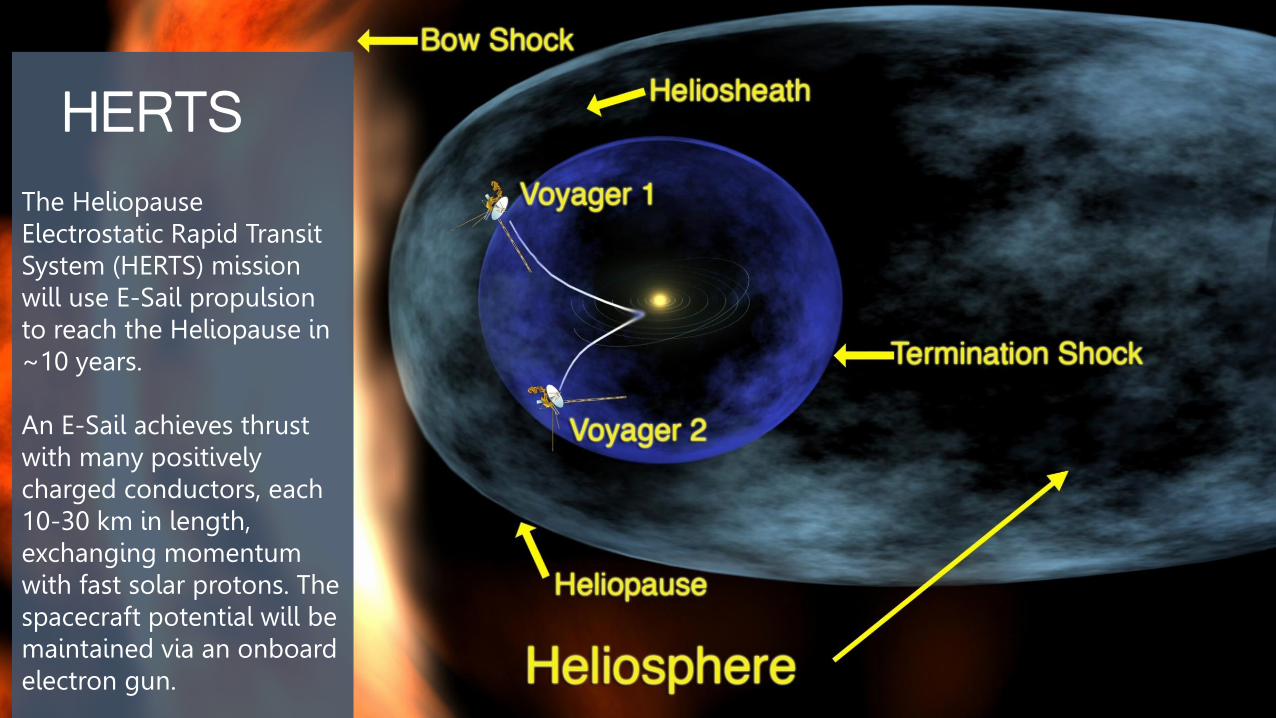
HERTSThe HeliopauseElectrostatic Rapid Transit System (HERTS) mission will use E-Sail propulsion to reach the Heliopause in ~10 years.
An E-Sail achieves thrust with many positively charged conductors, each 10-30 km in length, exchanging momentum with fast solar protons. The spacecraft potential will be maintained via an onboard electron gun.
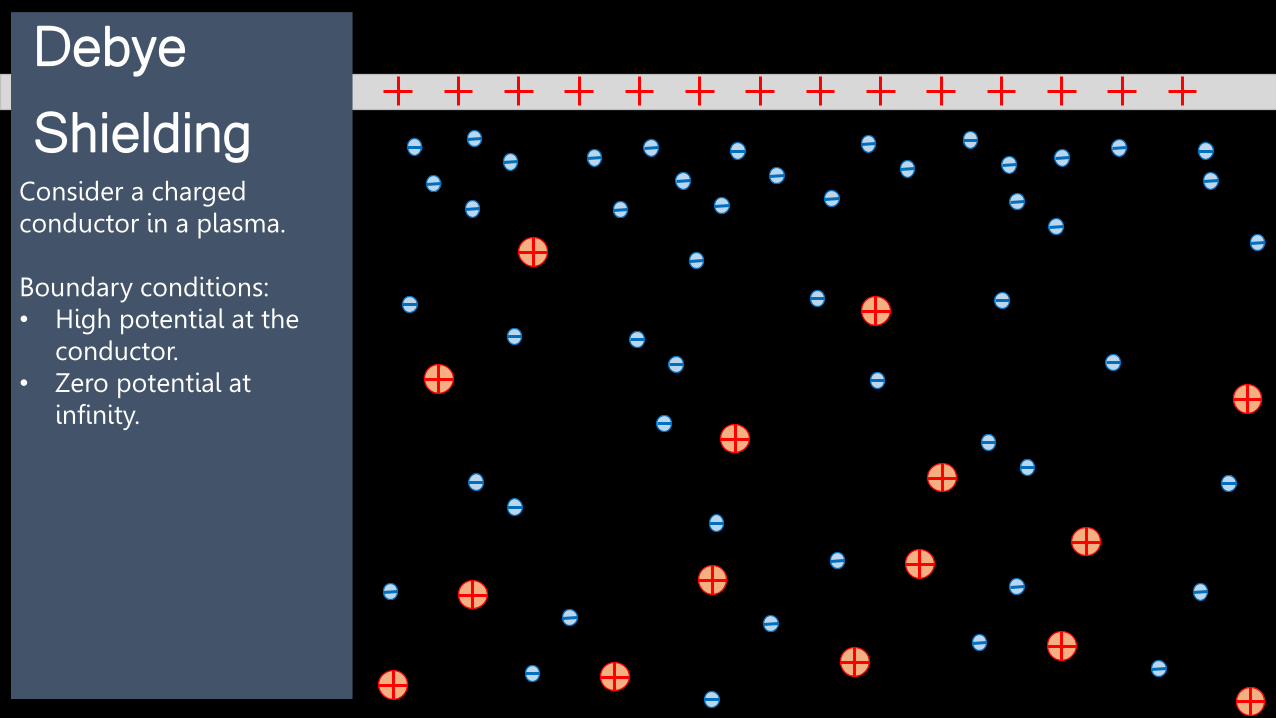
Debye Shielding
Consider a charged conductor in a plasma.
Boundary conditions:• High potential at the
conductor.• Zero potential at
infinity.

Debye Shielding
Potential
rConsider a charged conductor in a plasma.
Boundary conditions:• High potential at the
conductor.• Zero potential at
infinity.

Debye Shielding
Potential
r
𝜆𝐷
Consider a charged conductor in a plasma.
Boundary conditions:• High potential at the
conductor.• Zero potential at
infinity.
Solving Possion’s Equation for cold ions gives the characteristic length
𝜆𝐷 =𝜖0𝑘𝑇𝑒𝑛0𝑞𝑒
2
12

Debye Shielding
Potential
r
𝜆𝐷
Consider a charged conductor in a plasma.
Boundary conditions:• High potential at the
conductor.• Zero potential at
infinity.
Solving Possion’s Equation for cold ions gives the characteristic length
𝜆𝐷 =𝜖0𝑘𝑇𝑒𝒏𝟎𝑞𝑒
2
12
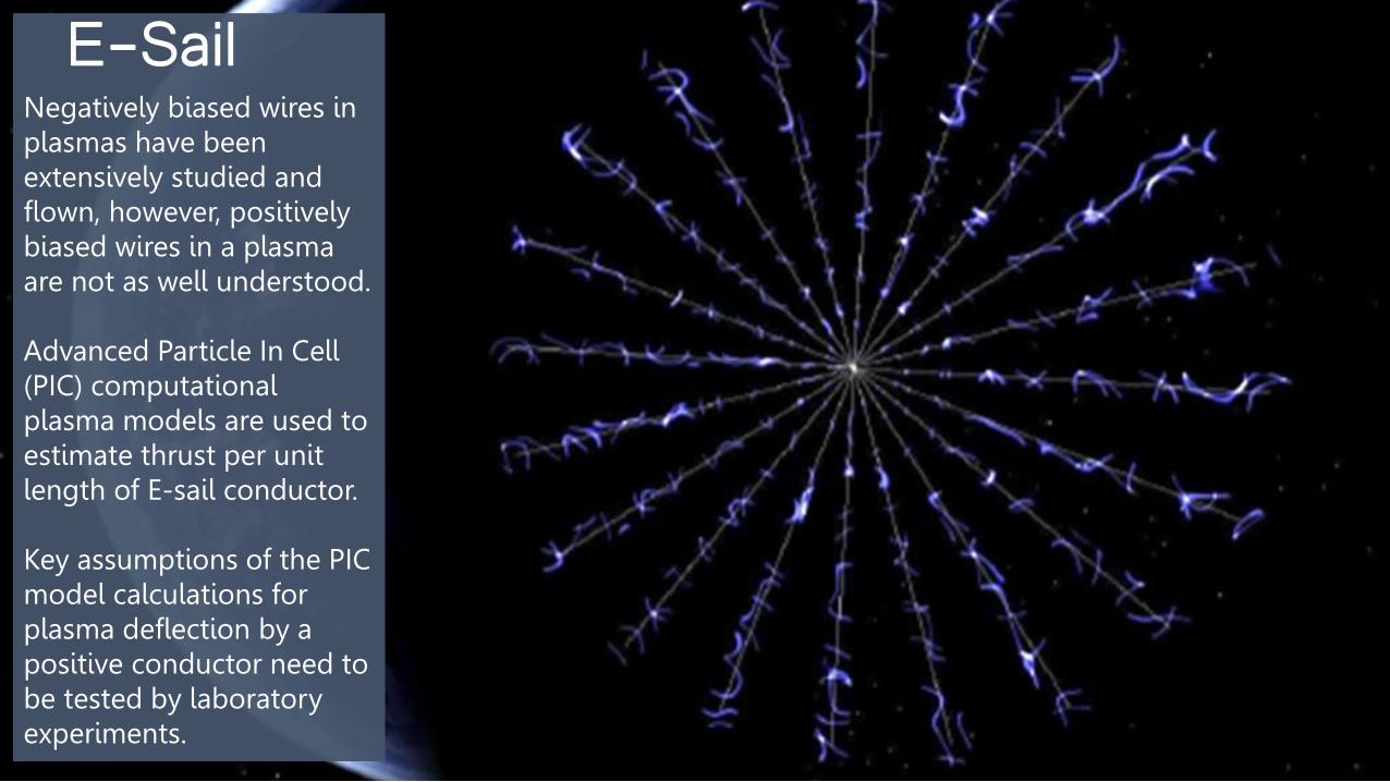
E-SailNegatively biased wires in plasmas have been extensively studied and flown, however, positively biased wires in a plasma are not as well understood.
Advanced Particle In Cell (PIC) computational plasma models are used to estimate thrust per unit length of E-sail conductor.
Key assumptions of the PIC model calculations for plasma deflection by a positive conductor need to be tested by laboratory experiments.

Test Plan• Set up Differential Ion Flux Probe
(DIFP) in plasma chamber.
• Verify the function and angular response of the DIFP.
• Map the free stream plasma.
• Test with test body in place (positively charged conductor).

DIFPDifferential Ion Flux Probe
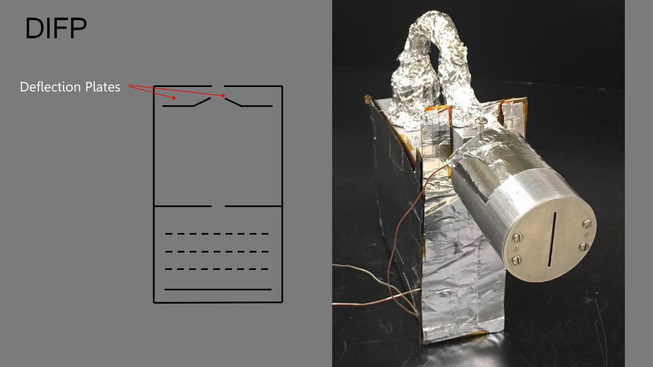
DIFP
Deflection Plates

DIFP
Deflection Plates
Repeller Grid
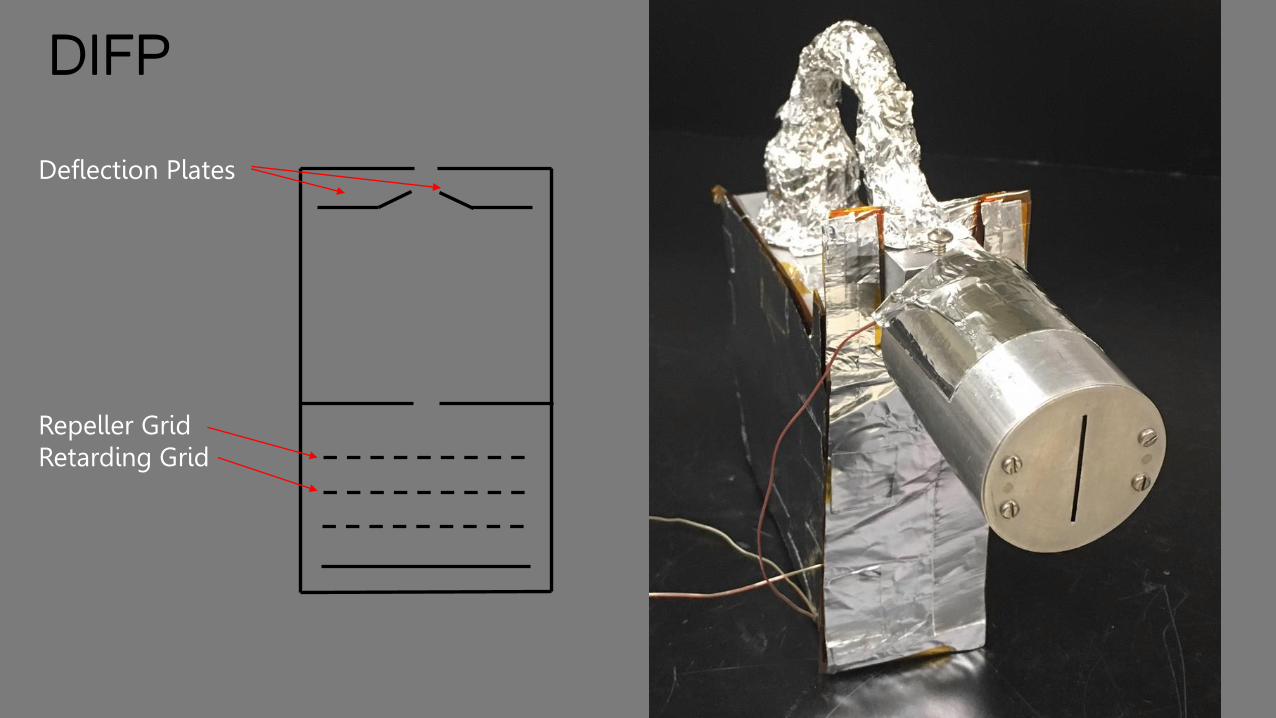
DIFP
Deflection Plates
Repeller GridRetarding Grid

DIFP
Deflection Plates
Repeller GridRetarding GridSuppressor Grid

DIFP
Deflection Plates
Repeller GridRetarding GridSuppressor Grid
Collector
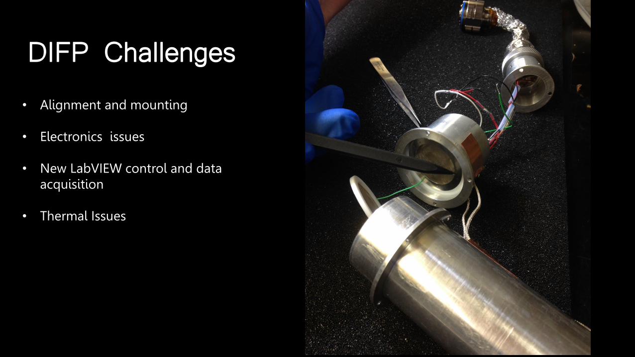
DIFP Challenges
• Alignment and mounting
• Electronics issues
• New LabVIEW control and data acquisition
• Thermal Issues

• Significant Electronics Troubleshooting
• Rudimentary MLI thermal shielding was added.
• Temperature sensitive electronics box moved to the chamber floor.
• Additional thermal shielding.
Solutions

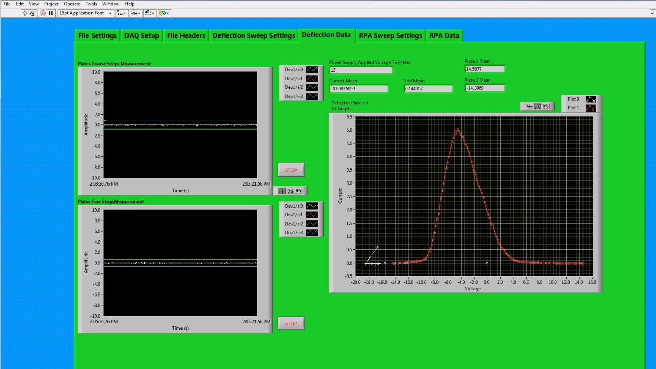
DIFPAngle Calibration• DIFP is rotated through a
set of known angles in a free stream plasma.
• Voltage swept on deflection plates.
• The deflection plate voltage with the peak ion current corresponds to the angle of the DIFP with respect to the plasma stream.

DIFPAngle Calibration• DIFP is rotated through a
set of known angles in a free stream plasma.
• Voltage swept on deflection plates.
• The deflection plate voltage with the peak ion current corresponds to the angle of the DIFP with respect to the plasma stream.

Free stream mapping
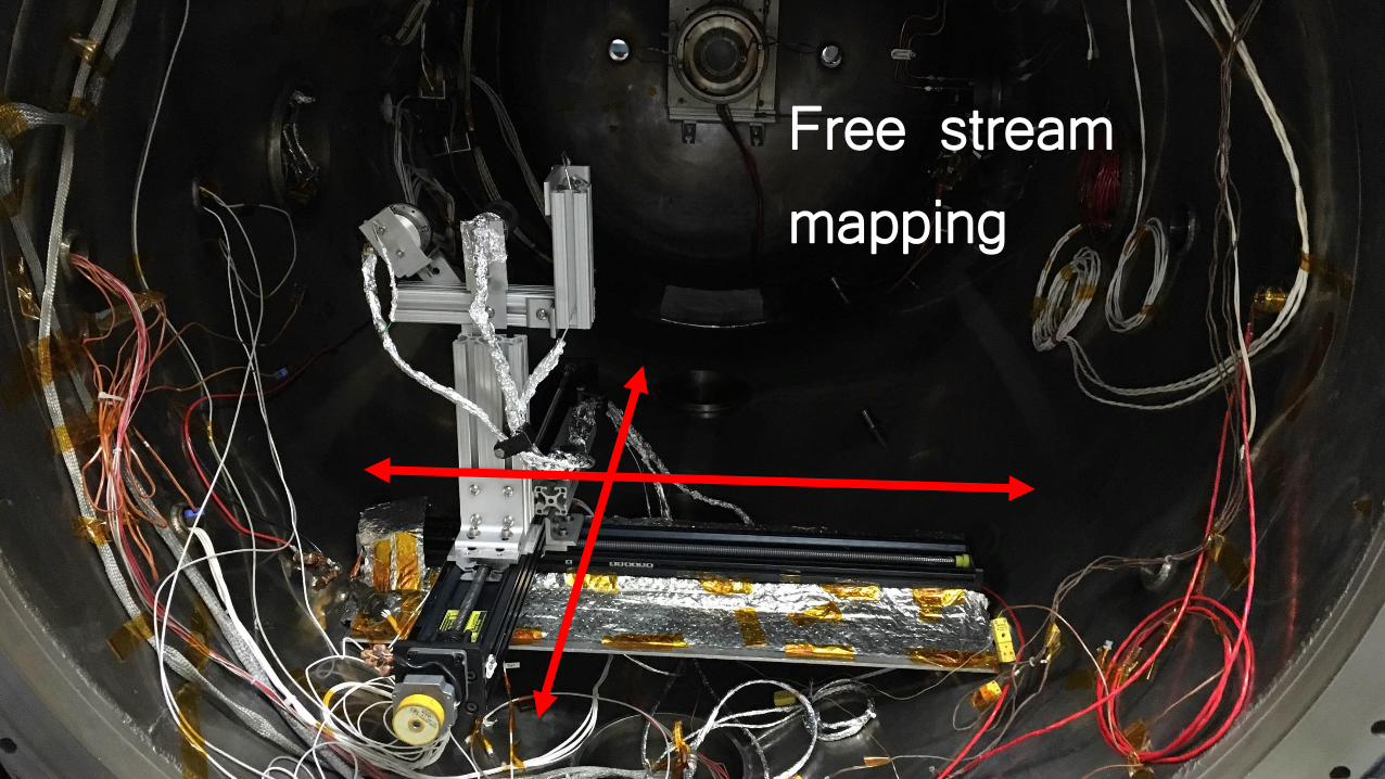
Free stream mapping

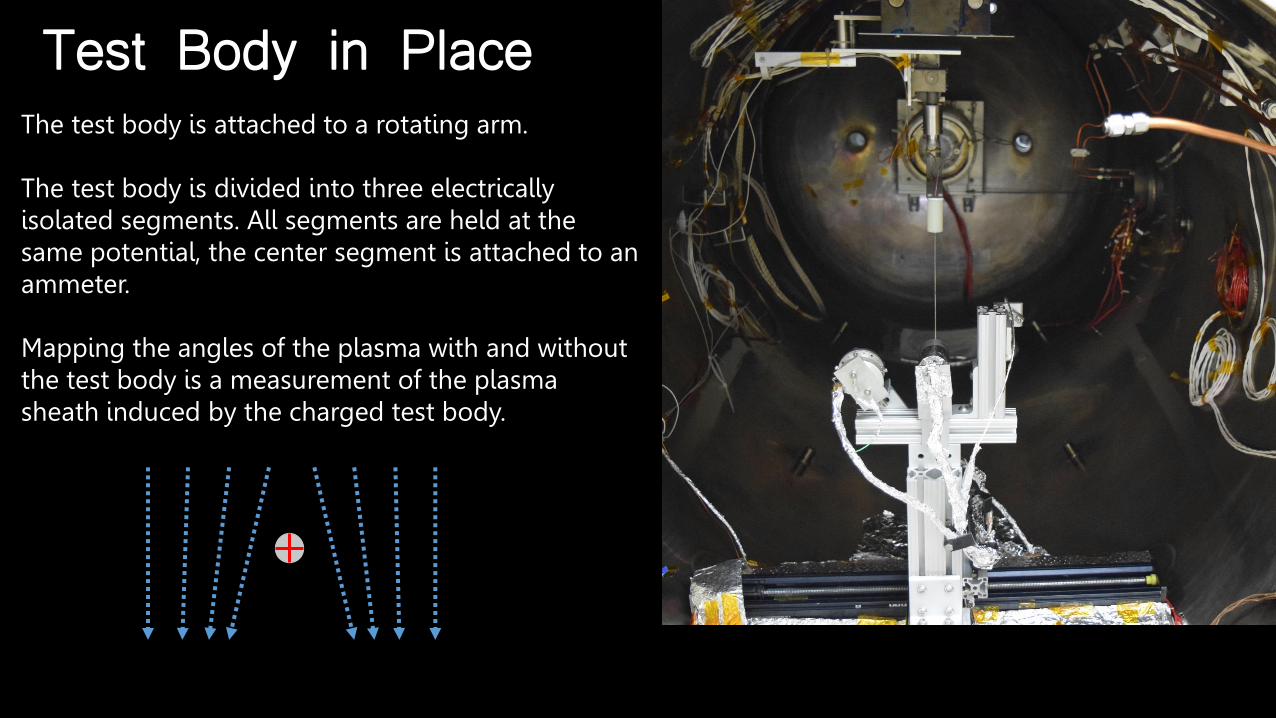
Test Body in PlaceThe test body is attached to a rotating arm.
The test body is divided into three electrically isolated segments. All segments are held at the same potential, the center segment is attached to an ammeter.
Mapping the angles of the plasma with and without the test body is a measurement of the plasma sheath induced by the charged test body.
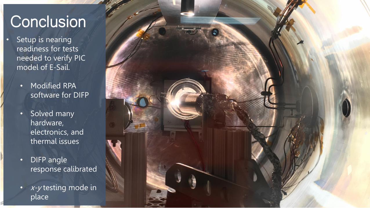
Conclusion• Setup is nearing
readiness for tests needed to verify PIC model of E-Sail.
• Modified RPA software for DIFP
• Solved many hardware, electronics, and thermal issues
• DIFP angle response calibrated
• x-y testing mode in place

DIFP data

RPA data