phonon-polariton physics: thermal conductivity, phonon ... · nanotech institute university of...
TRANSCRIPT

1
11Anvar A. Zakhidov, University of Texas at Dallas
NanoTech InstituteUniversity of Texas at Dallas
Phonon-Polariton Physics:
Thermal Conductivity, Phonon-Polariton Lasers and
Phonon Transistors in Nanostructures
Anvar Zakhidov on behalf of UTD PEOM Team
“DSRC Nanoscopic Phonon Engineering Workshop”
Booz Allen Hamilton, Arlington, May 9, 2005
22Anvar A. Zakhidov, University of Texas at Dallas
Outline :
Motivation for Tuning Phonon K(T) in Our 2 Main Systems.
System 1.
Phonon-Polaritons: New Mechanism of Thermal Conductivity PhononPhonon--PolaritonPolariton LasersLasers
Overview of PhononOverview of Phonon--PolaritonicsPolaritonics
System 2.
Carbon Nanotube Yarns and Sheets for Enhanced Thermal ConductivityPhonon Transistor with Charge Injection GatePhonon Transistor with Charge Injection Gate

Report Documentation Page Form ApprovedOMB No. 0704-0188
Public reporting burden for the collection of information is estimated to average 1 hour per response, including the time for reviewing instructions, searching existing data sources, gathering andmaintaining the data needed, and completing and reviewing the collection of information. Send comments regarding this burden estimate or any other aspect of this collection of information,including suggestions for reducing this burden, to Washington Headquarters Services, Directorate for Information Operations and Reports, 1215 Jefferson Davis Highway, Suite 1204, ArlingtonVA 22202-4302. Respondents should be aware that notwithstanding any other provision of law, no person shall be subject to a penalty for failing to comply with a collection of information if itdoes not display a currently valid OMB control number.
1. REPORT DATE 09 MAY 2005
2. REPORT TYPE N/A
3. DATES COVERED -
4. TITLE AND SUBTITLE Phonon-Polariton Physics: Thermal Conductivity, Phonon-PolaritonLasers and Phonon Transistors in Nanostructures
5a. CONTRACT NUMBER
5b. GRANT NUMBER
5c. PROGRAM ELEMENT NUMBER
6. AUTHOR(S) 5d. PROJECT NUMBER
5e. TASK NUMBER
5f. WORK UNIT NUMBER
7. PERFORMING ORGANIZATION NAME(S) AND ADDRESS(ES) NanoTech Institute University of Texas at Dallas
8. PERFORMING ORGANIZATIONREPORT NUMBER
9. SPONSORING/MONITORING AGENCY NAME(S) AND ADDRESS(ES) 10. SPONSOR/MONITOR’S ACRONYM(S)
11. SPONSOR/MONITOR’S REPORT NUMBER(S)
12. DISTRIBUTION/AVAILABILITY STATEMENT Approved for public release, distribution unlimited
13. SUPPLEMENTARY NOTES See also ADM001801., The original document contains color images.
14. ABSTRACT
15. SUBJECT TERMS
16. SECURITY CLASSIFICATION OF: 17. LIMITATION OF ABSTRACT
UU
18. NUMBEROF PAGES
33
19a. NAME OFRESPONSIBLE PERSON
a. REPORT unclassified
b. ABSTRACT unclassified
c. THIS PAGE unclassified
Standard Form 298 (Rev. 8-98) Prescribed by ANSI Std Z39-18

2
33Anvar A. Zakhidov, University of Texas at Dallas
Our Main Systems and Materials:
1. New Mechanism of Phonon-Polariton Thermal Conductivity
2. Carbon Nanotubes with Enhanced K(T) CNT in CNT Yarns and
Oriented CNT bucky-aerogels
44Anvar A. Zakhidov, University of Texas at Dallas
Our Main Concepts: “Solid State Heat Pipes”And “Phonon Transistor or Valve”
Two types of heat pipes:1. We predict an analog of optical fiber for heat transfer by lightmixed with optical phonon
Wave-guide in which Phonon-Polaritoncan propagate like light and contribute to K(T) of low-K organic matter
2. CNT are nanoscale analog of optical fibers in which phonons flow is ballistic and 1-d. Can it be a Heat-pipeHow to preserve this ballistic transport and high K in fibers of CNTs and CNT dispersed in polymers?
Polariton Heat transfer
Giant K(T) = 3000 – 6000 W/mK,Predicted in SWCNT and measured in MWCNTs
a) Conjugated Polymers-CNTfor distributed heat removal
in Organic Electronics
3-+
++
3-+
++
3-+
++3-+
++
3-+
++
3-+
++3-+
++
3-+
++
3-+
++
3-+
++3-+
++
3-+
++
3-+
++3-+
++
Low K Expect High Kupon unbundling
Charging

3
55Anvar A. Zakhidov, University of Texas at Dallas
Physical Ideas for Engineering Phonons at Nanoscale for Enhanced thermal conductivity K(T)
1. Optical Phonons dispersion is flat, group velocity small: no contribution to K(T)
2. It can be really engineered: changed to Phonon-Polariton with large Vg and we found sizable contribute to thermal conductivity K(T).
3. In Organic matter a Phonon-Laser is proposed, which can be pumped by heat and produce monochromatic and coherent IR
4. In single Carbon nanotubes phonons are ballistic and Lm ~1 µm, providing high K(T) for one CNT. Our Approach is to achieve and control high K(T) in real systems:
- unbundle tubes: decrease Phonon-Phonon scattering both inter-tube and UP- coat tubes with polymers and mix into a matrix of low-K conjugated
polymer at concentration lower or close to percolation for nano-scale distributed heat removal.
5. Phonon-Transistor concept appeared as a result of tunable K(T)
66Anvar A. Zakhidov, University of Texas at Dallas
DoD Needs Better Cooling Systems for Electronic Warfare Chips

4
77Anvar A. Zakhidov, University of Texas at Dallas
DARPA has a strong interest in Thermal Management: Previous HERETIC Program and Phonon EngineeringProgram are examples
88Anvar A. Zakhidov, University of Texas at Dallas
State-of-Art Heat Removal Circuitry Targets Fluids:Solid State Systems for cooling would be much more attractive for DoD Applications

5
99Anvar A. Zakhidov, University of Texas at Dallas
Impact 1: for Heat Management Circuitry for DoD Applications
Goal:Develop micro- and nano-scale solid state heat removal circuitry
with control devices (valves, couplers, switches,etc.) which can be Ultimately integrated with electronic and photonic circuitry.This technology will be unique, since it will enable controllable, adaptable,distributed and programmable thermal management
Impact: Efficient, compact and controllable (with active feedback)
heat removal circuitry will enable design of low power, small form-factorDoD systems, such as radars, high performance computers, and otherelectronic and photonic warfare subsystems
1010Anvar A. Zakhidov, University of Texas at Dallas
Our Concept: Solid State Cooling Circuitry Integrated on Chip,Heat Pipes (CNTs or “Polaritonic Fibers”
Active Cold Spots (by TEC)
PassiveCNT fibers and sheetsheat pipe in laminate
Novel light weightPolymer-CNT compositeHeat exchanger
Active Cold spots
Phonon-polaritonT-selective heat pipe
e.g. Kmax at 250K
CNT
Chips operating at low T
Phonon valvePolariton coupler

6
1111Anvar A. Zakhidov, University of Texas at Dallas
Photon-phonon mixed states:Polaritons will be usedfor Radiative heat transferinside thin films and “opticalfibers”
Carbon nanotube 1-d nano-heat-pipes arranged into fibers will be explored
Physical Concepts for Solid State Heat Pipes:1. Heat Transfer by Polaritons in Organic Thin Films 2. Achieve high K(T) of Carbon Nanotubes
with engineered Phonon-phonon interaction
1212Anvar A. Zakhidov, University of Texas at Dallas
PhononPhonon--PolaritonsPolaritons Contribution to Thermal Contribution to Thermal ConductivityConductivity
Prospects for Organic Phonon-PolaritonHeat Pipes
And Phonon-Polariton Laser
Overview of Polaritonics (MIT, France,)

7
1313Anvar A. Zakhidov, University of Texas at Dallas
• Known: by phonons, photons, electrons• New: by Phonon-Polaritons
• Bulk and Thin Films (Microcavity)• Ballistic regime: Λ(ω) > d
• Statistical, diffusive regime Λ(ω) << d
• Phonon-Polariton Microcavity Laser
Thermal conductivity
in solis:
1414Anvar A. Zakhidov, University of Texas at Dallas
Motivation
•Contribution of phonon-polaritons to thermal conductivity has never been estimated
(Klemens P.G. et al. Term. Conduct. (1988), 19, 453 )
•Phonon-polaritons can have very long mean free paths Λ(ω) of mm and even cm – ballistic propagation
•Enhancement of K(T) may be expected in nanostructureswith sizes, d smaller than Λ(ω)
In thick samples K(T) still can have contribution from polaritons

8
1515Anvar A. Zakhidov, University of Texas at Dallas
What is phonon-polariton?
Phonon + Photon = Phonon Polariton
Polariton is a mixed excitation, has phonon and electromagnetic components, and can propagate with high velocity
+=
ωLO
ωTO
1616Anvar A. Zakhidov, University of Texas at Dallas
POLARITONS vs PHOTONS
Photons in the Bulk , ε = ε∞ - constant
For Transverse Waves:
q2 e2/ ω2 = ε∞
ω = q e/√ε∞
Density of states Vs ω
Density of States:
DOS ~ q2 dq/(2π)3 ~ ω2 dω
Polaritons: Coherent mixture
of Photon with Phonon
DOS becomes singular at ωT

9
1717Anvar A. Zakhidov, University of Texas at Dallas
Phonon-Polaritons in Bulk: Dispersion and DOS
photons
Phonon-polarions
1818Anvar A. Zakhidov, University of Texas at Dallas
PHOTONS: Radiative Contribution to Thermal Conductivity in ballistic regime (Landauer)
φθθωωπ ω ddk
dkdk
ekJ TBkkz
cossin)))(()(1
1())2(
(2 /)(3
2h
h −= ∫
Total current J = JZ (T+∆T) - JZ (T)
3
2)2(26)(
⎟⎟⎠
⎞⎜⎜⎝
⎛≅
∆∞
∞ cTkck
TTJ BB
h
εεπ

10
1919Anvar A. Zakhidov, University of Texas at Dallas
Ballistic Propagation
[ ]coldhotdqddqqTJ ηηωωθ
πθ
εε
−=
=
∫∞
∞
cos)2(
sin2)(0
3
2
h
dxe
exc
TkckTTJ
x
xBB ∫
∞∞
∞ −⎟⎟⎠
⎞⎜⎜⎝
⎛=
∆ 02
43
2 )1()2()(
h
εεπ
But we have, 26)1(0
2
4
≅−∫
∞
dxe
exx
x
3
2)2(26)(
⎟⎟⎠
⎞⎜⎜⎝
⎛≅
∆∞
∞ cTkck
TTJ BB
h
εεπ
2020Anvar A. Zakhidov, University of Texas at Dallas
Phonon-Polaritons:Contribution to Thermal Conductivity:
Resonance with Optical Phonon at ω=ω⊥
⎟⎟⎠
⎞⎜⎜⎝
⎛
−
−=⎟
⎟⎠
⎞⎜⎜⎝
⎛
−
−=
⊥∞
⊥
∞22
22||
22
22||
2
22 )( ,
ωωωω
εωεωωωωωε
ck
⎪⎭
⎪⎬⎫
−⎟⎟⎠
⎞⎜⎜⎝
⎛
+−
−−+
+⎪⎩
⎪⎨⎧
−⎟⎟⎠
⎞⎜⎜⎝
⎛
+−
−−⎟⎟⎠
⎞⎜⎜⎝
⎛=
∆
∫
∫∞
⊥⊥
⊥
⊥⊥
⊥∞
∞
⊥
dxe
exxxxxxxxx
dxe
exxxxxxxxx
cTkck
TTJ
x
x
x
x
xxBB
BULK
2
4
222222
2222||
2
4
0222222
2222||
3
2
)1(4)())((
)1(4)())((
)2()(
||δ
δε
επ h
Tkx
Tkx
BB
|||| ,
ωω hh== ⊥
⊥

11
2121Anvar A. Zakhidov, University of Texas at Dallas
sphotons
Phonon-polarions
GROUPvDOS ×∝Γ )(ω
Major Difference: Density of States
2222Anvar A. Zakhidov, University of Texas at Dallas
0.3=∞ε
s
⊥
⊥−=
xxx||η
Resulting Enhancement of Heat Conductance
0 50 100 150 200 250 300
0
5
10
15
20
25
30
width=10-2
x⊥=566.4/T
BULK
Without resonance With Resonance
η=0.1 0.5 1.0
G(W
/m2 K
)
T(K)0 50 100 150 200 250 300
1
2
3
4
5
6
7
8
9
10
width=10-2
BULK x=566.4/T
η 0.1 0.2 0.3 0.4 0.5 0.8 1.0
GR
ES/G
NO
NR
ES
T(K)
for parameters of MgO

12
2323Anvar A. Zakhidov, University of Texas at Dallas
0 100 200 300 400 5001
2
3
4
5
6
7
8
9
10
ω=796cm-1
ε=6.52
η 0.1 0.2 0.4 0.6 0.8 1.0
GR
ES/G
NO
NR
ES
T(K)
Position of the enhancement peak is tunable
For parameters of phonon in SiC
2424Anvar A. Zakhidov, University of Texas at Dallas
0.0 0.2 0.4 0.6 0.8 1.0165
170
175
180
185
190
Pic
o P
ositi
on (K
)
η
0.0 0.2 0.4 0.6 0.8 1.0
128
132
136
140
144
Pic
o w
idth
(K)
η
The Dependence of T-Peak Position on the Tuning Parameter

13
2525Anvar A. Zakhidov, University of Texas at Dallas
Comparison of Polaritonic K(T) inSiC and MgO
0 200 400 600 800 10000
1
2
3
4
5
6
7
8
T= 176 K
T= 92 K
BULK
MgO SiC
GR
ES/G
NO
NR
ES
T(K)
2626Anvar A. Zakhidov, University of Texas at Dallas
Depends on:•Frequency ωTO• Line width δω
•Polaritonic gap ∆0 200 400 600 800 1000
1.0
1.2
1.4
1.6
1.8
2.0
2.2
ε=4.0
η=0.1
wres=10-2
w (cm-1) 100 394 796 1000 1500
GR
ES/
GN
ON
RE
S
0 200 400 600 800 1000
1.0
1.2
1.4
1.6
1.8
2.0
2.2
wres=10-5
η=0.1
0 200 400 600 800 10000
4
8
12
16
20
T(K)
η=1.0
0 200 400 600 800 10000
4
8
12
16
20η=1.0
To get a peak at RT, we need optical phonons with ωTO =1500 cm-1
Position and intensity of the enhancement peak is tunable

14
2727Anvar A. Zakhidov, University of Texas at Dallas
Thin Films: Radiative contribution to thermoconductivity
L
∞
==ε
πωL
cq )0(
Film thickness
L = λTO /2
2828Anvar A. Zakhidov, University of Texas at Dallas
Dispersion of Cavity polariton

15
2929Anvar A. Zakhidov, University of Texas at Dallas
GROUPMC vDOS ×∝Γ )(ω
3030Anvar A. Zakhidov, University of Texas at Dallas
Thin Films: Phonon-polariton contribution
to thermal conductivity
Thin films = Planar waveguides = Planar microcavities

16
3131Anvar A. Zakhidov, University of Texas at Dallas
Thin films: resulting enhancement of thermal conductivity
(Again from difference in DOS)
0 100 200 300 400
0
5
10
15
20
Resonance Non-Resonance
G(W
/m2 K
)
T(K)
MgO
3232Anvar A. Zakhidov, University of Texas at Dallas
0 100 200 300 400 500 600 700 800
0
20
40
60
80
100
120
140
ε=3.0x=566.7/T
wres=10-2
MC
GR
ES /G
NO
NR
ES
T(K)
Relative Enhancement of Heat Conductanceby Polaritonic Effect in
MICROCAVITY: The ratio of G res to G nonres
0.3=∞εMgO

17
3333Anvar A. Zakhidov, University of Texas at Dallas
Thick samples: Λ(ω) < dDiffusive heat transfer
3434Anvar A. Zakhidov, University of Texas at Dallas
Specific Heat C(ω)

18
3535Anvar A. Zakhidov, University of Texas at Dallas
Mean free path Λ(ω) of Phonon-Polaritons:
3636Anvar A. Zakhidov, University of Texas at Dallas
Check of Approximation for Λ(ω)
in MgO

19
3737Anvar A. Zakhidov, University of Texas at Dallas
Polaritonic K(T) in kinetic limit
3838Anvar A. Zakhidov, University of Texas at Dallas
Comparison of Polaritonic contribution with experimental K(T)

20
3939Anvar A. Zakhidov, University of Texas at Dallas
Promise of Fullerene M6C60 for Polaritonic K(T)
F4u optical IR mode is a great candidate forOP-Polariton with tunable K(T).
The intensity of optical absorption increase88 times (!) upon doping x=6 electrons in C60
Oscillator strength S ~ x2, increases dramatically,
Polariton Gap ( TO-LO splitting): ∆ ~ S1/2 , So that the parameter η ~ x
Polaritonc Thermal conductivity K(T) ~ η ~ x,
K becomes tunable by doping level x.K can be increased x times ( 6 in measured case)
4040Anvar A. Zakhidov, University of Texas at Dallas
1.1711.9660304LiF
0.7241.72424246NaF
1.0832.75425204LiCl
0.7191.85330192KF
1.0463.16354173LiBr
0.5982.31262164NaCl
0.8311.93293160RbF
0.5002.16216144KCl
0.5562.63210135NaBr
0.4962.14178119RbCl
0.5473.03181117NaI
0.4482.34168116Kbr
0.3982.59144103K-I
0.6604.04171103AgCl
0.6794.6213681AgBr
0.3732.6210375RbI
1.5165.116164TlCl
1.3755.4111448TlBr
ηε∞ω|| (cm-1)ω⊥ (cm-1)Material
⊥
⊥−=
ωωω
η ||
Map of materialsto chooseω and η

21
4141Anvar A. Zakhidov, University of Texas at Dallas
0.2196.52970796SiC
0.8252.956719394MgO
0.0989.1402366GaP
0.2745.2349274ZnS
0.303--305234CdS
0.8052.05464257CaF2
0.03614.4233225GaSb
0.7832.07387217SrF2
0.15712.3243210InAs
0.2213.71210172CuCl
0.8812.4380202CdFr
0.2415.9252203ZnSl
0.8262.16336184BaF2
0.11715.7200179InSb
0.1757.3208177ZnTl
0.251--214171CdSl
0.2217.2171140CdTl
ηε∞ω|| (cm-1)ω⊥ (cm-1)Material
Map of materialsto chooseω and η
4242Anvar A. Zakhidov, University of Texas at Dallas
Idea of IR Phonon-Lasers: Condensation of phonon-polaritons in planar
microcavities at Room-T•Exciton-polariton condensation has been recently demonstrated
in semiconductor MC.
•If condensation of lowest energy cavity phonon-polaritonsis achievable, IR lasing would
become possible with zero pumping threshold.
•The life-time of phonon-polaritons is a crucial parameter:
tlifetime > trelaxation
is needed
Lasing at KII =0

22
4343Anvar A. Zakhidov, University of Texas at Dallas
New Concepts:“Phonon-Polariton Laser”
1. We propose: Phonon-Polariton laser in the microcavity, pumped by heating
Polariton Heat transfer
Heater
T ~ 300 C
coolerHeat transfer by Polaritonic K
Mirror semi-transparent
Microcavity
Bose condensate ofPhonon-Polaritons
IR lasing beamwith ω = Ω op - ∆
4444Anvar A. Zakhidov, University of Texas at Dallas
Phonon-Polariton Laser• Polariton Laser - The polariton laser is a relatively new lasing
mechanism postulated by several research groups and recently observed in GaAs at cryogenic temperatures by a Japanese researcher visiting in the US. The laser operates on the principle of Bose-Einstein condensation of excitonic polaritons within microcavities to align phase, with radiation from the condensate. Theoretical calculations by Professor KavokinЃfs group indicate that the same opto-electronic effects will be possible in wide-bandgap semiconductors at room temperature. Their calculations show that the kinetic blocking of polaritonrelaxation preventing formation of the B-E condensation of polariton phase at low temperatures should disappear at higher temperatures. These lasers have very low threshhold currents, are very efficient, produce very little heat, and should have applications in very low power optical communications and optical computing.

23
4545Anvar A. Zakhidov, University of Texas at Dallas
European Activities
• New Laser Principle for Low Power and Fast Optoelectronic Devices:Dr. Harvey, of ARL-ERO, visited Blaise Pascal University, FR, to discuss new room temperature lasing mechanism based on Bose-Einstein condensation in wide-bandgap semiconductor microcavities. This opens the door to very low power laser communications, THz optical signal processing, quantum computing, spintronic devices, THz modulation in photonic bandgap structures, and THz electronic signal processing. Such devices will enable the communication and processing of the massive amounts of data necessary to support FCS concepts. The Physics Dept at, Blaise Pascal University, has a very strong theoretical program and a good experimental program which is focusing on electron-light interactions in semiconductors, in particular excitonic polariton effects in semiconductor microcavities. Professor Kavokin leads a European collaboration funded by the European Community and focused on phenomena in semiconductor microcavities under the EC Framework program on “High Technology for Communications and Information Processing”.
4646Anvar A. Zakhidov, University of Texas at Dallas
Polariton Transistor
• THz Excitonic Polariton Transistor and THz Optoelectronic Devices - The Blaise Pascal group has shown theoretically and experimentally that the excitonic polaritons can be accelerated in the plane of microcavities, with the gradient of the microcavitythickness acting as the forcing function. Observed velocities are one to two orders of magnitude faster than the electronic ballistic transport in bulk semiconductors, with the potential for using the polaritons as carriers in a very fast transistor type device and for ultrafast optical processing.
•

24
4747Anvar A. Zakhidov, University of Texas at Dallas
Polaritonics: bridging the gap between electronics and photonics
• Between electronics and photonics there exists a frequency gap of approximately 2 octaves, i.e. the frequency range between 100~GHz and 10~THz. Here we demonstrate that phonon-polaritons in ferroelectric crystals like LiNbO$_3$ or LiTaO$_3$ may be able to bridge this gap. The ability to fabricate structures within the crystal by femtosecond laser machining facilitates all integrated signal guiding and processing. Spatiotemporal imaging is employed for direct visualization of the electromagnetic field within the crystal. Polaritonic resonators, waveguides, photonic crystals and focusing, dispersive, and diffractive elements will be demonstrated.
• Authors: David Ward, Thomas Feurer, Eric Stats, JoushuaVaughan, Keith Nelson, Massachusetts Institute of Technology)
4848Anvar A. Zakhidov, University of Texas at Dallas
Conclusions on K(T) by Phonon-Polaritons1. Ph-Polaritons are found to contribute to K(T) of thin films, with T-peak.
Position of T-peak depends on Ω op, the line width of OP and the TO-LO splitting,
2. K(T) can be 10-20 times stronger than the conventional radiative contribution to K by free photons.
3. T-peak shifts to lowest T in microcavities (L ~ 1-10 µm), which can be used in cryogenic heat transfer.
4. To create a material with high enough polaritonic K(T) at RT, compared to the usual, phonon Kphone should create an organic material with OP at 1500-2000 cm-1, which has large oscillator strengthIn organic materials Kph is usually low (< 0.1-1 W/mK), the Kpol can become a main contribution.
5. One candidate for polaritonic heat pipe, can be a doped fullerene film MxC60 in which a giant oscillator strength S enhancement is found, which is quadratic in doping level x: S ~ x2.
6.The strong dependence of Kpol(T) on S(x) leads to tunability of K(T) by charge transferand thus may be used in “polariton-transistors”, in which K can be amplified by charging gate G.
7. Phonon-Polaritons can be used for “Polariton-lasers”, which will emit monochromaticand coherent IR radiation, due to Bose-Einstein condensation in microcavity.

25
4949Anvar A. Zakhidov, University of Texas at Dallas
Our Main Systems and Materials:
1. New Mechanism of Phonon-Polariton Thermal Conductivity
2. Carbon Nanotube Systems with Enhanced K(T) CNT:
- CNT Fibers and Yarns and - Oriented CNT-ribbon aerogels
5050Anvar A. Zakhidov, University of Texas at Dallas
PHONON TRANSISTOR inNANOTUBE FIBERS with Electrochemical Gate
Capacitance of 134 F/gm, versus usual 15-30 F/gm.Electrolyte: 1.0 M tetrathylammonium hexafluorophosphate in acetonitrile.
Increased capacitance results from debundling. (Raman measurements of radial breathing mode shifts.)
3-+
++
3-+
++
3-+
++3-+
++
3-+
++
3-+
++3-+
++
3-+
++
3-+
++
3-+
++3-+
++
3-+
++
3-+
++3-+
++Low K Expect High K upon unbundlingCharging the bundles
Debundling should decrease tube-tube phonon scattering, and increase K(T) dramatically:
Phonon Transistor
50 100 150 200 250 300T0
200
400
600
800
1000
ka WmK
∆K

26
5151Anvar A. Zakhidov, University of Texas at Dallas
SEM images of PurifiedUnannealed Oleum -spun
HiPCo fibers
Before cycling in EMIImFiber diameter Å 50 µm
After cycling in EMIImFiber diameter Å 100 µm
51
Prove of Unbundling: Twice Increased Diameter of Fibers
Transistor in ‘ON” statePhonon Transistor in ‘OFF” state
5252Anvar A. Zakhidov, University of Texas at Dallas
Phonon Transistor withElectrochemical Charge Injection Gate
C= charge/voltageC= Area × dielectric constant /dArea/weight is above 300 m2/gm;d is in nanometers
Gate function:
Charge injection will cause changein tube-tube interaction, which changesΩ of intertube phonon and modulate The Tube-Tube scattering.
Modulation of Thermal Conductivity K(T)
Increased K(T) upon G voltage

27
5353Anvar A. Zakhidov, University of Texas at Dallas
Charging Setup:
• SWNT paper was used to charge and study the effect of charge injection in field emission characteristics. SWNT paper was was used as both the positive and negative electrode.
• Chronopotentiometry was used for performing the double layer charging. Princeton model 273A instrument contains both a potentiostat and a galvanostat, and hence can perform both controlled potential (potentiostatic) and controlled current (galvanostatic) experiments.
• Cyclic Voltametry was also performed before the charging by cycling from –0.2 to 0.9V. The direction of the potential is reversed at the end of the first scan. This has the advantage that the product of the electron transfer reaction that occurred in the forward scan can be probed again in the reverse scan. It is a powerful tool for the determination of formal redox potentials, detection of chemical reactions that precede or follow the electrochemical reaction and evaluation of electron transfer kinetics.
5454Anvar A. Zakhidov, University of Texas at Dallas
Charging I-t Curves
Capacitance of SWCNT paper is very large: C ~ 20-30 F/g

28
5555Anvar A. Zakhidov, University of Texas at Dallas
Tuning K by Charge Injection
0.0 0.5 1.0 1.5 2.0 2.5 3.0
50
100
150
200
250
300
αcharged Na, 10Hz=12.6 mm2/sαcharged Cl, 10Hz=11.5 mm2/s
αpristine, 5 Hz = 10.8 mm2/sαcharged Na, 5 Hz =12.9 mm2/sαcharged Cl, 5 Hz =11.5 mm2/sPh
ase
shift
, deg
ree
Distance, mm
HipCO (15x0.5 mm), prisitine Wetted in 2M NaCl, washed DI Charged, Na+, 1h, 0.8V Charged overnight, Na+, 0.8V Charged overnight, repeated Charged overnight, repeated, 10 Hz Charged Cl, 10 Hz Charged Cl, 5 Hz
5656Anvar A. Zakhidov, University of Texas at Dallas
Tuning K by Charge Injection:A Step towards Phonon Transistor
0.0 0.5 1.0 1.5 2.0
50
100
150
200
250
300
350
400
450Two MagAlign SWNT(II) paper electrodes charged at 0.5V for 1h
Phas
e sh
ift, d
egre
e
Distance, mm
Cl- α = 14.2 mm2/s Pristine α = 15.2 mm2/s Na+ α = 21.6 mm2/s
Thermal diffusivity and thus thermalConductivity of CNT is provedto be tuned by Charge injection into
Oriented CNT paper at V = 0.5 V
Effect is 25 %:
From D = 15.2 mm2/s to 21.6 mm2/s
29
5757Anvar A. Zakhidov, University of Texas at Dallas
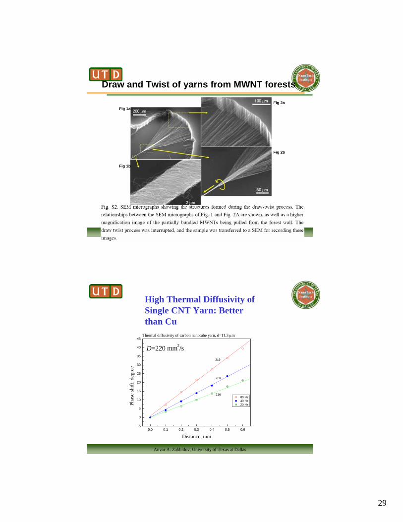
Draw and Twist of yarns from MWNT forests
Fig 1a
Fig 1b
Fig 2a
Fig 2b
5858Anvar A. Zakhidov, University of Texas at Dallas
0.0 0.1 0.2 0.3 0.4 0.5 0.6-5
0
5
10
15
20
25
30
35
40
45Thermal diffusivity of carbon nanotube yarn, d=11.3 µm
D=220 mm2/s
216
220
219
Phas
e sh
ift, d
egre
e
Distance, mm
80 Hz 40 Hz 20 Hz
High Thermal Diffusivity of Single CNT Yarn: Better than Cu

30
5959Anvar A. Zakhidov, University of Texas at Dallas
Thermal conductivity of Single CNT Yarn: Better than Cu
• The thermal conductivity λ of single-strand MWNT yarn was obtained at room temperature from the relationship λ= ρCpD , by measuring the thermal diffusivity D, density ρ, and specific heat capacity Cp. The measurements of D were carried out using the laser flash technique.
• One end of a specimen of length L is uniformly irradiated by a laser beam Q=Qosin ωt.
•• λ= ρСpD = 0.8 g/cm3 0.715 J/gK 2.20 cm2/s = • 1.25 W/cmK = 125 W/mK,• where the specific heat capacity of graphite with density 2.26 g/cm2:
Cp(300K) = 8.58 J/(mol K) = 0.715 J/gK [1], (For comparison the specific heat capacity value for 10 μm Amoco P-55 carbon fibers, with density of 2 g/cm2 at 25oC is 0.717 J/gK [2]), ρ=0.8 g/cm3 is the density of fiber, andD=2.20 cm2/s is the thermal diffusivity of the fiber.
• For comparison, the thermal diffusivity of thin wire (100µm) of copper and gold are much lower: Dcopper = 117 mm2/s, Dgold = 130 mm2/s.
6060Anvar A. Zakhidov, University of Texas at Dallas
Multifunctional Carbon Nanotube Yarns by Downsizing an Ancient TechnologyM. Zhang, Ken Atkinson, Ray Baughman, Science 306 (2004) 1358
‘Draw-Twist’ process to convert MWNT
in a forest to ‘Twisted Yarns’

31
6161Anvar A. Zakhidov, University of Texas at Dallas
SEM images of ‘Twisted Yarns’
6262Anvar A. Zakhidov, University of Texas at Dallas
Oriented Multiwall CNT Thin Sheets:Aerogels with strongly anisotropic K(T)

32
6363Anvar A. Zakhidov, University of Texas at Dallas
NanoTech Institute MWNTSheet Fabrication Process
Sheets (presently 5 cm X 1 m) are fabricated At 3 m/minute. These width and length are not fundamentally limited and the rate is limited by our present draw apparatus.
We have promising initial results for diverse applications: * transparent elastomeric electrodes; * light-emitting diodes; * incandescent sources of polarized light; * two-dimensionally reinforced composites; & microwave absorbing appliqués
6464Anvar A. Zakhidov, University of Texas at Dallas
Spun nanotube sheets as an incandescent light source.
The light output is polarized, with a degree of polarization that increases withwave length from 0.6 at 500 nm to 0.66 at 780 nm.

33
6565Anvar A. Zakhidov, University of Texas at Dallas
400 500 600 700 800
0.0
1.0x10⁻²
2.0x10⁻²
3.0x10⁻²
4.0x10⁻²
5.0x10⁻²
a)
II
⊥
Rad
ianc
e ( W
/sr/m
2 )
Wavelength ( nm )
U = 50V ⊥ 1st measurement ⊥ 2nd measurement II 1st measurement II 2nd measurement
1 layer ribbon
400 500 600 700 80010-6
10-5
10-4
10-3
10-2
10-1
b)
II⊥
Rad
ianc
e ( W
/sr/m
2 )
Wavelength ( nm )
U = 50V ⊥ 1st measurement ⊥ 2nd measurement II 1st measurement II 2nd measurement
1 layer ribbon
Polarized Emission of Nanotube Sheet Incandescent Light Source
Spectral radiance of incandescent light from single sheet of parallel carbon nanotubes: a) linear scale, b) semi logarithmic scale. The solid line in a) is a fit by black body radiation with T=1350 K.
6666Anvar A. Zakhidov, University of Texas at Dallas
0
20
40
60
80
100
200 600 1000 1400 1800 2200Wavelength (nm)
Tran
smit
(%)
Polarizer Alignment:
Perpendicular
Parallel
Optical Transparency of MWNT Sheet
Resistance: ~600 Ω/ (in aligned direction)~15 KΩ/ (in cross direction)