phonon-mediated magnetic polaritonsin the infrared region
TRANSCRIPT
Phonon-mediated magnetic polaritons in the infrared region
L. P. Wang and Z. M. Zhang*
George W. Woodruff School of Mechanical Engineering Georgia Institute of Technology, Atlanta, GA 30332 USA
Abstract: Magnetic polaritons that couple electromagnetic waves with magnetic excitation can be used for tailoring the radiative properties of materials in energy-harvesting and other applications. Previous studies used metallic microstructures to induce magnetic responses. With rigorous coupled-wave analysis (RCWA), transmission enhancement with a SiC slit array and coherent thermal emission with a SiC deep grating is theoretically demonstrated in the infrared within the phonon absorption band. The field distributions and the agreement in the resonance frequencies predicted from both RCWA and LC circuit models strongly suggest that magnetic polaritons exist in the SiC microstructures. This type of magnetic polariton is mediated by vibration of atoms in polar materials (i.e., optical phonons), rather than by free electrons in metals. Our results suggest that phonon-mediated magnetic polaritons have promising applications such as filters and selective coherent emitters in the infrared spectral region.
©2011 Optical Society of America
OCIS codes: (160.3918) Metamaterials; (240.5420) Polaritons; (260.5740) Resonance.
References and links
1. W. S. Cai, U. K. Chettiar, A. V. Kildishev, and V. M. Shalaev, “Optical cloaking with metamaterials,” Nat. Photonics 1(4), 224–227 (2007).
2. J. Valentine, S. Zhang, T. Zentgraf, E. Ulin-Avila, D. A. Genov, G. Bartal, and X. Zhang, “Three-dimensional optical metamaterial with a negative refractive index,” Nature 455(7211), 376–379 (2008).
3. J. B. Pendry, “Negative refraction makes a perfect lens,” Phys. Rev. Lett. 85(18), 3966–3969 (2000). 4. J. B. Pendry, A. J. Holden, D. J. Robbins, and W. J. Stewart, “Magnetism from conductors and enhanced
nonlinear phenomena,” IEEE Trans. Microw. Theory Tech. 47(11), 2075–2084 (1999). 5. S. Linden, C. Enkrich, M. Wegener, J. F. Zhou, T. Koschny, and C. M. Soukoulis, “Magnetic response of
metamaterials at 100 terahertz,” Science 306(5700), 1351–1353 (2004). 6. C. Enkrich, M. Wegener, S. Linden, S. Burger, L. Zschiedrich, F. Schmidt, J. F. Zhou, T. Koschny, and C. M.
Soukoulis, “Magnetic metamaterials at telecommunication and visible frequencies,” Phys. Rev. Lett. 95(20), 203901 (2005).
7. A. N. Lagarkov, and A. K. Sarychev, “Electromagnetic properties of composites containing elongated conducting inclusions,” Phys. Rev. B Condens. Matter 53(10), 6318–6336 (1996).
8. V. A. Podolskiy, A. K. Sarychev, and V. M. Shalaev, “Plasmon modes in metal nanowires and left-handed materials,” J. Nonlinear Opt. Phys. Mater. 11(1), 65–74 (2002).
9. V. M. Shalaev, W. S. Cai, U. K. Chettiar, H. K. Yuan, A. K. Sarychev, V. P. Drachev, and A. V. Kildishev, “Negative index of refraction in optical metamaterials,” Opt. Lett. 30(24), 3356–3358 (2005).
10. J. F. Zhou, L. Zhang, G. Tuttle, T. Koschny, and C. M. Soukoulis, “Negative index materials using simple short wire pairs,” Phys. Rev. B 73(4), 041101 (2006).
11. S. Zhang, W. J. Fan, N. C. Panoiu, K. J. Malloy, R. M. Osgood, and S. R. J. Brueck, “Experimental demonstration of near-infrared negative-index metamaterials,” Phys. Rev. Lett. 95(13), 137404 (2005).
12. J. A. Schuller, T. Taubner, and M. L. Brongersma, “Optical antenna thermal emitters,” Nat. Photonics 3(11), 658–661 (2009).
13. Q. Zhao, L. Kang, B. Du, H. Zhao, Q. Xie, X. Huang, B. Li, J. Zhou, and L. Li, “Experimental demonstration of isotropic negative permeability in a three-dimensional dielectric composite,” Phys. Rev. Lett. 101(2), 027402 (2008).
14. L. Peng, L. X. Ran, H. S. Chen, H. F. Zhang, J. A. Kong, and T. M. Grzegorczyk, “Experimental observation of left-handed behavior in an array of standard dielectric resonators,” Phys. Rev. Lett. 98(15), 157403 (2007).
15. Z. M. Zhang, Nano/Microscale Heat Transfer (McGraw-Hill, 2007). 16. F. Marquier, K. Joulain, J. P. Mulet, R. Carminati, J. J. Greffet, and Y. Chen, “Coherent spontaneous emission of
light by thermal sources,” Phys. Rev. B 69(15), 155412 (2004).
(C) 2011 OSA 14 March 2011 / Vol. 19, No. S2 / OPTICS EXPRESS A126#138948 - $15.00 USD Received 30 Nov 2010; revised 12 Jan 2011; accepted 17 Jan 2011; published 27 Jan 2011
17. F. Marquier, K. Joulain, and J. J. Greffet, “Resonant infrared transmission through SiC films,” Opt. Lett. 29(18), 2178–2180 (2004).
18. S. Shen, A. Narayanaswamy, and G. Chen, “Surface phonon polaritons mediated energy transfer between nanoscale gaps,” Nano Lett. 9(8), 2909–2913 (2009).
19. E. Rousseau, A. Siria, G. Jourdan, S. Volz, F. Comin, J. Chevrier, and J. J. Greffet, “Radiative heat transfer at the nanoscale,” Nat. Photonics 3(9), 514–517 (2009).
20. S. Basu, Z. M. Zhang, and C. J. Fu, “Review of near-field thermal radiation and its application to energy conversion,” Int. J. Energy Res. 33(13), 1203–1232 (2009).
21. Y. De Wilde, F. Formanek, R. Carminati, B. Gralak, P. A. Lemoine, K. Joulain, J. P. Mulet, Y. Chen, and J. J. Greffet, “Thermal radiation scanning tunnelling microscopy,” Nature 444(7120), 740–743 (2006).
22. H. Liu, T. Li, Q. J. Wang, Z. H. Zhu, S. M. Wang, J. Q. Li, S. N. Zhu, Y. Y. Zhu, and X. Zhang, “Extraordinary optical transmission induced by excitation of a magnetic plasmon propagation mode in a diatomic chain of slit-hole resonators,” Phys. Rev. B 79(2), 024304 (2009).
23. L. P. Wang, and Z. M. Zhang, “Resonance transmission or absorption in deep gratings explained by magnetic polaritons,” Appl. Phys. Lett. 95(11), 111904 (2009).
24. B. J. Lee, L. P. Wang, and Z. M. Zhang, “Coherent thermal emission by excitation of magnetic polaritons between periodic strips and a metallic film,” Opt. Express 16(15), 11328–11336 (2008), http://www.opticsinfobase.org/oe/abstract.cfm?URI=oe-16-15-11328.
25. L. Wang, and Z. M. Zhang, “Effect of magnetic polaritons on the radiative properties of double-layer nanoslit arrays,” J. Opt. Soc. Am. B 27(12), 2595–2604 (2010).
26. M. G. Moharam, E. B. Grann, D. A. Pommet, and T. K. Gaylord, “Formulation for stable and efficient implementation of the rigorous coupled-wave analysis of binary gratings,” J. Opt. Soc. Am. A 12(5), 1068–1076 (1995).
27. B. J. Lee, Y.-B. Chen, and Z. M. Zhang, “Transmission enhancement through nanoscale metallic slit arrays from the visible to mid-infrared,” J. Comput. Theor. Nanosci. 5, 201–213 (2008).
28. N. Engheta, “Circuits with light at nanoscales: optical nanocircuits inspired by metamaterials,” Science 317(5845), 1698–1702 (2007).
29. J. F. Zhou, E. N. Economon, T. Koschny, and C. M. Soukoulis, “Unifying approach to left-handed material design,” Opt. Lett. 31(24), 3620–3622 (2006).
30. J. Zhou, T. Koschny, M. Kafesaki, E. N. Economou, J. B. Pendry, and C. M. Soukoulis, “Saturation of the magnetic response of split-ring resonators at optical frequencies,” Phys. Rev. Lett. 95(22), 223902 (2005).
31. N. Dahan, A. Niv, G. Biener, Y. Gorodetski, V. Kleiner, and E. Hasman, “Enhanced coherency of thermal emission: Beyond the limitation imposed by delocalized surface waves,” Phys. Rev. B 76(4), 045427 (2007).
1. Introduction
Electromagnetic metamaterials have advanced at a fast pace during the past decade, with exciting applications such as optical cloaking [1], negative refraction [2], and perfect lenses [3]. To obtain negative index materials (NIMs), it is essential to simultaneously achieve negative permittivity (ε) and permeability (μ). However, most naturally occurring materials do not respond to magnetic fields at optical frequencies. Several structures have been demonstrated to exhibit a magnetic response at optical frequencies, thereby realizing electromagnetic metamaterials with exotic behaviors. Split-ring resonators were the structure first proposed by Pendry et al. [4] to possess negative μ. In order to scale the magnetic resonance to the near infrared, single-split-ring [5] and U-shape [6] unit cells were subsequently introduced.
Diamagnetism is responsible for the magnetic response in split-ring and U-shape structures. According to Lenz’s law, when a time-varying magnetic field is introduced perpendicular to the plane of the structure, an oscillating current will be produced in the metal structure that creates an induced magnetic field. Such a diamagnetic response can also occur in a short-strip (or short-rod, short-wire) pair, since antiparallel currents are induced in the strips. The electromagnetic response of pairs of metal rods in a dielectric medium was initially studied by Lagarkov and Sarychev [7]. Podolskiy et al. [8] showed that both negative permittivity and permeability can exist in the near-infrared and visible frequencies, resulting in negative refractive index, from paired-wire composites. Later, negative index was experimentally observed by Shalaev et al. [9] with a double-layer periodic gold nanorod array and by Zhou et al. [10] with a paired-copper-wire structure. Sandwiched fishnet structures, consisting of perforated metal films separated by a dielectric spacer, were also shown to exhibit negative refractive index [11]. Valentine et al. [2] experimentally demonstrated negative refraction in the near infrared with a fishnet structure composed of alternating layers
(C) 2011 OSA 14 March 2011 / Vol. 19, No. S2 / OPTICS EXPRESS A127#138948 - $15.00 USD Received 30 Nov 2010; revised 12 Jan 2011; accepted 17 Jan 2011; published 27 Jan 2011
of Ag and MgF2. With these artificial structures, also called “magnetic atoms”, electromagnetic waves can interact with materials via both electric and magnetic fields.
The aforementioned “magnetic atoms” are made of metals or in a metal-insulator-metal configuration. Recent studies have demonstrated that negative permeability and negative refractive index can be realized based on the Mie resonance with dielectric metamaterials, such as SiC rods [12], a 3D composite consisting of dielectric ceramic cubes [13], and an array of dielectric cylinders [14]. Unlike in metallic structures where conductive current is responsible for diamagnetism, the dielectric metamaterials are based on the displacement current. However, a large positive permittivity is required to satisfy the Mie resonance condition for a magnetic response. Thus, suitable materials and tunable frequency ranges are rather limited.
Polar materials such as SiC exhibit a negative real part of permittivity within the phonon absorption band, also called the reststrahlen band [15]. This metal-like behavior enables the excitation of a surface phonon polariton (SPhP) as the counterpart of surface plasmon polariton (SPP) for metals. Indeed, free electrons in metals and bound electrons in polar materials can give similar responses at optical frequencies. SPhPs have been employed to construct coherent thermal emission sources [16], which can emit thermal radiation in a narrow spectral band either isotropically or in well-defined directional lobes. SPhPs are also useful for the transmission enhancement through SiC slit arrays [17]. Furthermore, the coupling of evanescent waves associated with SPhPs could boost the energy transfer in near-field thermal radiation, and this has been demonstrated experimentally [18–20]. Moreover, the evanescent field at the surfaces where SPhPs are excited could be utilized in near-field thermal imaging without external illumination [21].
Magnetic polaritons have been demonstrated to tailor thermal radiative properties in metallic structures [22–25]. The present work reveals the existence of magnetic polariton within the phonon absorption band of SiC. Two simple periodic structures, a slit array and a deep grating, were considered here for applications as an infrared filter and a coherent thermal emission source, respectively. The rigorous coupled-wave analysis (RCWA) [26] was used to calculate the radiative properties at normal incidence and dispersion relations. The existence of magnetic polaritons in the SiC structures was examined by the comparison between RCWA calculations and equivalent LC circuit models on the resonant condition. The geometric effects on the resonant condition were also investigated. The electromagnetic field distribution was finally presented at the excitation of magnetic polaritons, and the underlying mechanism was discussed.
2. Numerical results from RCWA
The geometries of the slit array and the deep grating are shown as insets in Figs. 1(a) and 1(b), respectively. For the deep grating, the underlying SiC is treated as a semi-infinite medium. The plane of incidence is assumed perpendicular to the grooves here, and transverse magnetic (TM) plane waves are considered with a time-harmonic magnetic field parallel to the grooves. The radiative properties, such as the spectral-directional reflectance R and transmittance T, were computed at given frequencies and angles of incidence (θ) from RCWA. For the deep grating structure, the spectral-directional emittance (or emissivity) can
be calculated from ε = 1R according to Kirchhoff’s law. Sufficient Fourier terms representing the dielectric function in the grating region must be used to ensure computational accuracy [26,27]. Here, a total of 101 Fourier terms were used and, compared to the results obtained with 201 terms, the difference in the predicted reflectance or transmittance is negligibly small. The dielectric function of SiC may be described by the Lorentz phonon oscillator model:
2 2
LO TO
SiC 2 2
TO
( ) 1ii
(1)
(C) 2011 OSA 14 March 2011 / Vol. 19, No. S2 / OPTICS EXPRESS A128#138948 - $15.00 USD Received 30 Nov 2010; revised 12 Jan 2011; accepted 17 Jan 2011; published 27 Jan 2011
where ν is the wavenumber, 6.7 is the high frequency constant, γ = 4.76 cm1
is the
damping coefficient, and νLO = 969 cm1
and νTO = 793 cm1
are the longitudinal and transverse optical phonon frequencies, respectively [15].
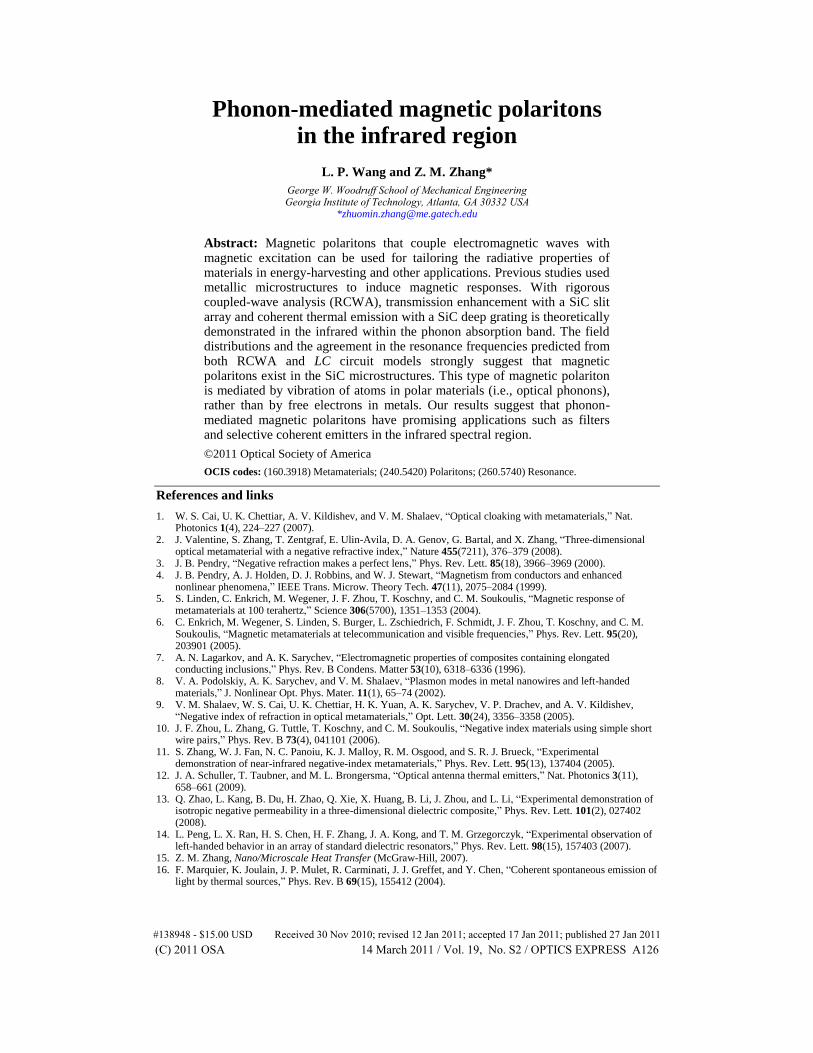
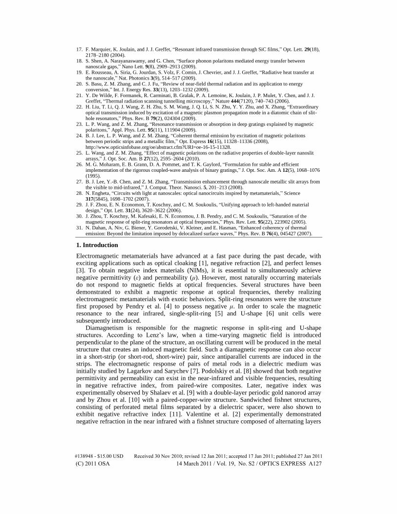
Fig. 1. Microstructures made of SiC and calculated radiative properties. (a) Calculated spectral-directional reflectance R (dashed) and transmittance T (solid) at normal incidence for the slit array structure, shown as inset along with the LC circuit model. (b) Calculated spectral-directional reflectance R (dashed) and emittance ε (solid) at normal incidence for the deep grating structure, shown as inset along with the LC circuit model.
Figures 1(a) and 1(b) show the calculated radiative properties for the corresponding structure represented in the insets in the reststrahlen band of SiC at normal incidence. The period Λ is 5 μm and the strip width w is 4.5 μm for both structures, while the height h is 3 μm for the slit array and 1 μm for the deep grating, respectively. Reflectance dips can be seen
in the spectra of both structures. A transmittance peak occurs at 836.5 cm1
with a magnitude of 0.676, indicating transmission enhancement by the slit array. Two emittance peaks can be
seen in Fig. 1(b): the first at 852.5 cm1
has a peak value of 0.734 and the second at 928.7
cm1
has a smaller peak of 0.244. The emission peaks can be applied as selective coherent thermal emission sources. It should be mentioned that both structures are highly reflective for
(C) 2011 OSA 14 March 2011 / Vol. 19, No. S2 / OPTICS EXPRESS A129#138948 - $15.00 USD Received 30 Nov 2010; revised 12 Jan 2011; accepted 17 Jan 2011; published 27 Jan 2011
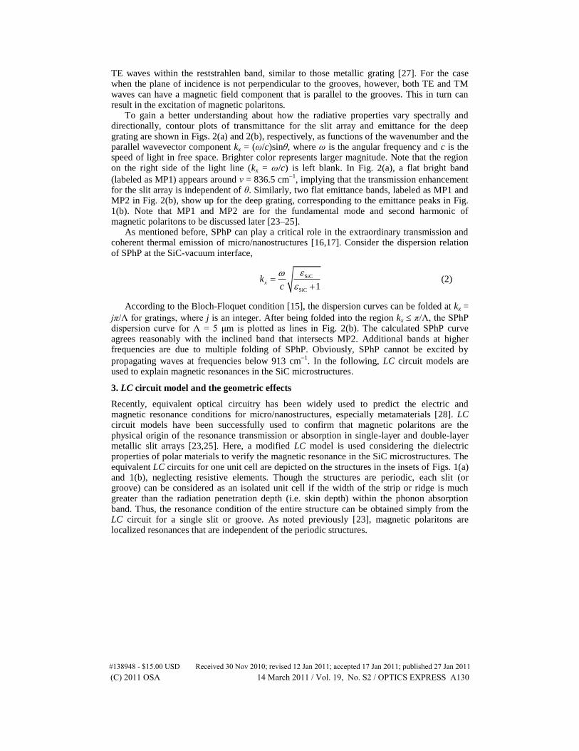
TE waves within the reststrahlen band, similar to those metallic grating [27]. For the case when the plane of incidence is not perpendicular to the grooves, however, both TE and TM waves can have a magnetic field component that is parallel to the grooves. This in turn can result in the excitation of magnetic polaritons.
To gain a better understanding about how the radiative properties vary spectrally and directionally, contour plots of transmittance for the slit array and emittance for the deep grating are shown in Figs. 2(a) and 2(b), respectively, as functions of the wavenumber and the parallel wavevector component kx = (ω/c)sinθ, where ω is the angular frequency and c is the speed of light in free space. Brighter color represents larger magnitude. Note that the region on the right side of the light line (kx = ω/c) is left blank. In Fig. 2(a), a flat bright band
(labeled as MP1) appears around ν = 836.5 cm1
, implying that the transmission enhancement for the slit array is independent of θ. Similarly, two flat emittance bands, labeled as MP1 and MP2 in Fig. 2(b), show up for the deep grating, corresponding to the emittance peaks in Fig. 1(b). Note that MP1 and MP2 are for the fundamental mode and second harmonic of magnetic polaritons to be discussed later [23–25].
As mentioned before, SPhP can play a critical role in the extraordinary transmission and coherent thermal emission of micro/nanostructures [16,17]. Consider the dispersion relation of SPhP at the SiC-vacuum interface,
SiC
SiC 1xk
c
(2)
According to the Bloch-Floquet condition [15], the dispersion curves can be folded at kx =
jπ/Λ for gratings, where j is an integer. After being folded into the region kx π/Λ, the SPhP dispersion curve for Λ = 5 μm is plotted as lines in Fig. 2(b). The calculated SPhP curve agrees reasonably with the inclined band that intersects MP2. Additional bands at higher frequencies are due to multiple folding of SPhP. Obviously, SPhP cannot be excited by
propagating waves at frequencies below 913 cm1
. In the following, LC circuit models are used to explain magnetic resonances in the SiC microstructures.
3. LC circuit model and the geometric effects
Recently, equivalent optical circuitry has been widely used to predict the electric and magnetic resonance conditions for micro/nanostructures, especially metamaterials [28]. LC circuit models have been successfully used to confirm that magnetic polaritons are the physical origin of the resonance transmission or absorption in single-layer and double-layer metallic slit arrays [23,25]. Here, a modified LC model is used considering the dielectric properties of polar materials to verify the magnetic resonance in the SiC microstructures. The equivalent LC circuits for one unit cell are depicted on the structures in the insets of Figs. 1(a) and 1(b), neglecting resistive elements. Though the structures are periodic, each slit (or groove) can be considered as an isolated unit cell if the width of the strip or ridge is much greater than the radiation penetration depth (i.e. skin depth) within the phonon absorption band. Thus, the resonance condition of the entire structure can be obtained simply from the LC circuit for a single slit or groove. As noted previously [23], magnetic polaritons are localized resonances that are independent of the periodic structures.
(C) 2011 OSA 14 March 2011 / Vol. 19, No. S2 / OPTICS EXPRESS A130#138948 - $15.00 USD Received 30 Nov 2010; revised 12 Jan 2011; accepted 17 Jan 2011; published 27 Jan 2011
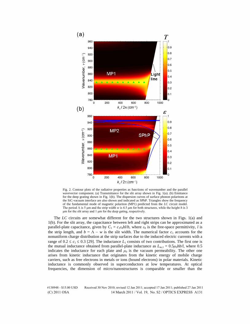
Fig. 2. Contour plots of the radiative properties as functions of wavenumber and the parallel wavevector component. (a) Transmittance for the slit array shown in Fig. 1(a). (b) Emittance for the deep grating shown in Fig. 1(b). The dispersion curves of surface phonon polaritons at the SiC-vacuum interface are also shown and indicated as SPhP. Triangles show the frequency of the fundamental mode of magnetic polariton (MP1) predicted from the LC circuit model. The period Λ is 5 μm and the strip width w is 4.5 μm for both structures, while the height h is 3 μm for the slit array and 1 μm for the deep gating, respectively.
The LC circuits are somewhat different for the two structures shown in Figs. 1(a) and 1(b). For the slit array, the capacitance between left and right strips can be approximated as a parallel-plate capacitance, given by C1 = c1ε0hl/b, where ε0 is the free-space permittivity, l is
the strip length, and b = Λ w is the slit width. The numerical factor c1 accounts for the nonuniform charge distribution at the strip surfaces due to the induced electric currents with a
range of 0.2 c1 0.3 [29]. The inductance L1 consists of two contributions. The first one is the mutual inductance obtained from parallel-plate inductance as Lm,1 = 0.5μ0hb/l, where 0.5 indicates the inductance for each plate and μ0 is the vacuum permeability. The other one arises from kinetic inductance that originates from the kinetic energy of mobile charge carriers, such as free electrons in metals or ions (bound electrons) in polar materials. Kinetic inductance is commonly observed in superconductors at low temperatures. At optical frequencies, the dimension of micro/nanostructures is comparable or smaller than the
(C) 2011 OSA 14 March 2011 / Vol. 19, No. S2 / OPTICS EXPRESS A131#138948 - $15.00 USD Received 30 Nov 2010; revised 12 Jan 2011; accepted 17 Jan 2011; published 27 Jan 2011
wavelength, and the contribution from the kinetic inductance becomes comparable to or even larger than the magnetic inductance [30].
The frequency-dependent complex conductivity of SiC can be expressed as i .
The complex impedance k( )k kZ R i L is inversely proportional to the conductivity, i.e.,
1
k eff[( ) ]Z s i A . Here, s is the distance the induced current circulates in the open loop
and Aeff is the effective cross-sectional area for the induced electric current due to the skin
effect and nonuniform charge distribution. Since for SiC in the absorption band,
one obtains k eff/ ( )L s A . Using the relationship
0 [15], the kinetic
inductance can be approximated as 2
k 0 eff/ ( )L s A . Note that the real part of the
dielectric function of SiC is negative for νTO < ν < νLO. By assuming that the induced current flows near the strip surface within a depth approximately equal to the power penetration depth δ = λ/(4πκ) [15], where κ is the extinction coefficient of SiC, the kinetic inductance for the slit
array can be expressed as 2
k,1 0/ ( )L h l . Note that the extinction coefficient κ can be
obtained from εSiC = (n + iκ)2 using Eq. (1), and the resulting δ is less than 1 μm in the
frequency range from 781.4 cm1
to 953.8 cm1
with a minimum of 53.4 nm at 794.3 cm1
. Therefore, the total impedance of the LC circuit shown in Fig. 1(a) can be expressed by
tot,1 m,1 k,1 2
1
12Z i L L
C
(3)
The magnetic resonance condition ωR,1 for the fundamental mode of magnetic polaritons can be obtained by finding the root of Ztot,1 = 0. Note that it is an implicit equation since
and δ are frequency-dependent. Similarly, the magnetic resonance condition for the deep
grating can be solved by zeroing
tot,2 m,2 k,2 2
2
1Z i L L
C
(4)
where Lm,2 = μ0hb/l is the magnetic inductance based on the coil inductance,
2
k,2 02 / ( )L h b l is the kinetic inductance of the cavity, and C2 = c2ε0hl/b is the
gap capacitance. Again, a numerical factor c2 is introduced to account for the nonuniform charge distribution between the ridges of the grating. Since there is only one capacitor C2 in the circuit for the deep grating, rather than two C1 for the slit array, the reasonable range for c2 can be estimated as twice of that of c1. It is worth mentioning that the magnetic resonance conditions are independent of the length l, i.e., the dimension in the y direction.
The exact values of the numerical factors c1 and c2 are difficult to determine without knowing the detailed charge distribution near the strip surfaces. Here, c1 = 0.2 and c2 = 0.55 are chosen for the LC models to fit well the resonant conditions of MP1 in Fig. 1. It is
expected that c2 2c1 since the charge distribution in the deep grating should be different from that in the slit array due to the existence of SiC substrate. The fundamental modes of the
magnetic polariton predicted by the LC circuit model are at 833.1 cm1
for the slit array and
858.5 cm1
for the deep grating, respectively, and are indicated as triangles in Figs. 2(a) and 2(b). The magnetic resonance frequency is independent of kx, and this distinguishes magnetic polaritons from the Fabry-Perot-type cavity resonance.
Figure 3 shows how the magnetic resonant frequencies change with one varying geometric parameter such as height h, slit width b or period Λ while other parameters are kept at base values as those in Fig. 1. The contour plots obtained from RCWA at normal incidence exhibit multiple bright bands, indicating either transmission or emission enhancement for slit arrays or deep grating respectively. In Figs. 3(a) and 3(b), the resonance frequency decreases with increasing height for a specific mode, suggesting that the frequencies for the enhanced transmission or emission peaks can be tuned by varying the height. The LC model prediction
(C) 2011 OSA 14 March 2011 / Vol. 19, No. S2 / OPTICS EXPRESS A132#138948 - $15.00 USD Received 30 Nov 2010; revised 12 Jan 2011; accepted 17 Jan 2011; published 27 Jan 2011

for the fundamental mode (MP1) is shown with triangles, which match well with the resonance band obtained from RCWA. At high frequencies, the LC prediction deviates from the RCWA result, because of the interaction with SPhPs similar to those observed for metallic slit arrays [23,25]. Higher-order modes of magnetic polaritons also occur for thicker slit arrays or deeper gratings, marked as MP2 and MP3 in the figures.
The slit width effect on the resonant frequency can be seen from Figs. 3(c) and 3(d) for both structures. Larger slit width will result in increased resonant frequency. The LC circuit model prediction agrees well with RCWA results at low frequencies. However, the existence
of SPhPs around 940 cm1
causes the suppression of magnetic polaritons at higher frequencies, resulting in larger discrepancies between RCWA and LC calculations.
Fig. 3. Geometric effects on the magnetic polaritons for (a, c, e) the slit array and (b, d, f) the deep grating: (a, b) height h effect, (c, d) slit width b effect, and (d, f) period Λ effect. MP1 represents the fundamental mode and MP2 or MP3 denotes high-order modes of magnetic polaritons. The fundamental mode of the magnetic resonance frequency calculated from the LC circuit model is shown as triangles.
(C) 2011 OSA 14 March 2011 / Vol. 19, No. S2 / OPTICS EXPRESS A133#138948 - $15.00 USD Received 30 Nov 2010; revised 12 Jan 2011; accepted 17 Jan 2011; published 27 Jan 2011

Furthermore, under the assumption that the strip width is much larger than the penetration depth, the LC model predicts that the period should have no influence on the resonant condition of magnetic polaritons for both structures. This can be seen from the triangles that are aligned horizontally in Figs. 3(e) and 3(f) for slit arrays and deep gratings, respectively. However, large deviations between RCWA results and LC model prediction on the resonance frequency of MP1 can be seen for small Λ values. This is because the individual slit or groove cannot be treated isolated anymore for small strip width, and the assumption for LC model is not valid. As the period increases, the contour plots based on RCWA calculation show that the resonance frequency of MP1 decreases. This again is attributed to the interaction with SPhPs. Due to the folding of SPhP dispersion curves, the excitation condition for SPhPs at normal incidence will shift to lower frequencies for larger grating periods. Even though the simple LC model is not able to consider the interaction with SPhPs, it predicts the resonant condition of MP1 within 3% from RCWA results for the periods from 3 μm to 10 μm. Subsequently, the magnetic polaritons are suppressed to lower frequencies. In general, the LC prediction agrees well with RCWA calculations, demonstrating that magnetic polaritons are indeed responsible for the transmission or emission enhancement in the SiC structures.
4. Electromagnetic field distributions
The electromagnetic field distributions calculated by the RCWA at the excitation frequencies are plotted in Fig. 4 at normal incidence. The contour plots indicate the logarithm of the square of the magnetic field and the arrows represent the electric field vectors. Figures 4(a)
and 4(b) show the field patterns for MP1 excited at 836.5 cm1
for the slit array and at 852.5
cm1
for the deep grating, with the same geometries used in Figs. 1(a) and 1(b), respectively. The field distribution reveals strong magnetic field confinement (up to an order of magnitude greater than that of the incidence wave) inside the slit or groove between the neighboring SiC strips or ridges. The electric field circulates around the slit or groove to form a loop, denoted by ovals with arrows indicating the direction, associated with the antinode of the magnetic field. This is the typical characteristic of the diamagnetic response. The number of induced electric loops or that of antinodes of the magnetic field indicates the order of the magnetic polaritons. The transmission or absorption (emission) enhancement arises as a result of the field confinement.
The field distributions for MP2 are shown in Figs. 4(c) and 4(d), but with different heights (h = 6.64 μm for the slit array and h = 4.28 μm for the deep grating) in order to obtain the same resonance frequency as MP1 for the corresponding structure. Similar behavior for the magnetic and electric fields can be seen with two antinodes, indicating the second-harmonic mode of magnetic polariton. It should be emphasized that MP2 helps localize more energy than MP1 into the cavity region, so that ε = 0.981 can be achieved for the deep grating at MP2. Coherent thermal emission using dielectric deep grating structures has been proposed [31], but the underlying mechanism was attributed to cavity resonance modes without considering magnetic polaritons. The insight gained in this work is useful for the design of deep gratings as coherent thermal emission sources.
The field distributions of magnetic polaritons in the SiC microstructures show similar features as that in similar metallic structures: strong magnetic field localization and induced electric currents [24,25]. Nevertheless, there exists a fundamental difference. In metals, the induced electric current is caused by the motion of free charges such as free electrons, whereas in polar materials, the vibration of ions or bound charges at high frequencies creates the electric current. In other words, magnetic polaritons excited inside polar materials are mediated by optical phonons. Examples of such materials include SiO2, CaF2, GaAs, GaN, MgF2, MgO, ZnSe, Al2O3, TiO2, SrTiO3, etc. Proper selection of materials will allow tuning the transmittance and reflectance spectra for infrared applications, as well as building coherent thermal emission sources at high temperatures for energy harvesting.
(C) 2011 OSA 14 March 2011 / Vol. 19, No. S2 / OPTICS EXPRESS A134#138948 - $15.00 USD Received 30 Nov 2010; revised 12 Jan 2011; accepted 17 Jan 2011; published 27 Jan 2011
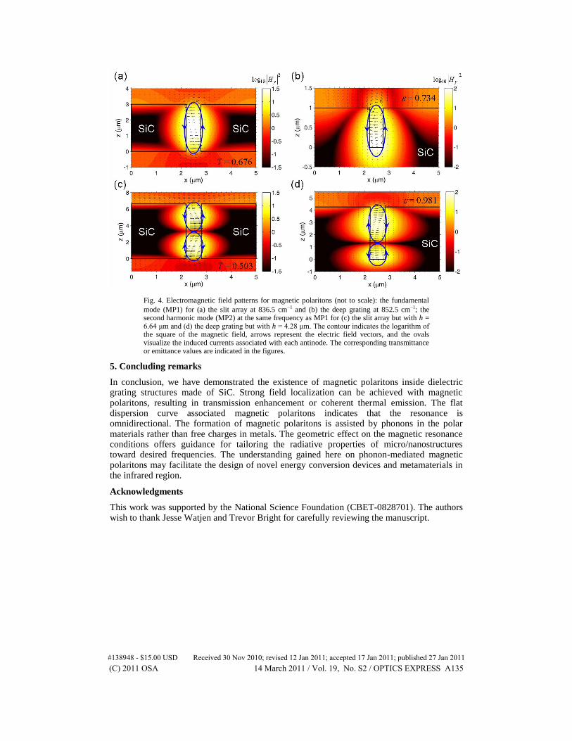
Fig. 4. Electromagnetic field patterns for magnetic polaritons (not to scale): the fundamental
mode (MP1) for (a) the slit array at 836.5 cm1 and (b) the deep grating at 852.5 cm1; the second harmonic mode (MP2) at the same frequency as MP1 for (c) the slit array but with h = 6.64 μm and (d) the deep grating but with h = 4.28 μm. The contour indicates the logarithm of the square of the magnetic field, arrows represent the electric field vectors, and the ovals visualize the induced currents associated with each antinode. The corresponding transmittance or emittance values are indicated in the figures.
5. Concluding remarks
In conclusion, we have demonstrated the existence of magnetic polaritons inside dielectric grating structures made of SiC. Strong field localization can be achieved with magnetic polaritons, resulting in transmission enhancement or coherent thermal emission. The flat dispersion curve associated magnetic polaritons indicates that the resonance is omnidirectional. The formation of magnetic polaritons is assisted by phonons in the polar materials rather than free charges in metals. The geometric effect on the magnetic resonance conditions offers guidance for tailoring the radiative properties of micro/nanostructures toward desired frequencies. The understanding gained here on phonon-mediated magnetic polaritons may facilitate the design of novel energy conversion devices and metamaterials in the infrared region.
Acknowledgments
This work was supported by the National Science Foundation (CBET-0828701). The authors wish to thank Jesse Watjen and Trevor Bright for carefully reviewing the manuscript.
(C) 2011 OSA 14 March 2011 / Vol. 19, No. S2 / OPTICS EXPRESS A135#138948 - $15.00 USD Received 30 Nov 2010; revised 12 Jan 2011; accepted 17 Jan 2011; published 27 Jan 2011