phone: 866-356-1992 | email: … 866-356-1992 | email: [email protected] | address: 315 - a...
TRANSCRIPT


Phone: 866-356-1992 | Email: [email protected] | Address: 315 - A Industrial RD Summerville, SC 29483
Product Support: Eccotemp.com/help-desk Shop Online: Eccotemp.com/products Store Locater: Eccotemp.com/locater
PLEASE NOTE: THIS MANUAL IS SUBJECT TO CHANGE AT ANYTIME, TO ENSURE THIS MANUAL IS UP TO DATE PLEASE VISIT OUR HELP DESKAT WWW.ECCOTEMP.COM FOR ALL OF OUR PRODUCT MANUALS.
RISK OF ELECTRICSHOCK
TANKLESS ELECTRIC WATER HEATER
4002422
MODEL #:
iE-11RATING: 240Vac, 60Hz, 11000W
FLOW RATE: 0.85-3.2 GPM
REQUIRED RATING OF CIRCUIT BREAKER:60A
CONFORMS TO UL STD. 499CERTIFIED TO CSA STD. C22.2 NO.64-10
SERIAL NUMBER:
MADE IN CHINA
CAUTION & ATTENTION:
FOR HOUSEHOLD AND INDOOR USEONLY
POUR LES MENAGESETL’ UTILISTATION A L’INTERIEUR
SEULEMENT.
Eccotemp Systems, LLC315-A Industrial Road
Summerville, SC 29483866-356-1992
TANKLESS ELECTRIC WATER HEATER
4002422
MODEL #:
iE-15BRATING: 240Vac, 60Hz, 15000W
FLOW RATE: 0.85-3.2 GPM
REQUIRED RATING OF CIRCUIT BREAKER:80A
CONFORMS TO UL STD. 499CERTIFIED TO CSA STD. C22.2 NO.64-10
SERIAL NUMBER:
MADE IN CHINA
CAUTION & ATTENTION:
FOR HOUSEHOLD AND INDOOR USEONLY
POUR LES MENAGESETL’ UTILISTATION A L’INTERIEUR
SEULEMENT.
Eccotemp Systems, LLC315-A Industrial Road
Summerville, SC 29483866-356-1992
RISK OF ELECTRICSHOCK
TANKLESS ELECTRIC WATER HEATER
Eccotemp Systems, LLC315-A Industrial Road
Summerville, SC 29483866-356-1992
4002422
MODEL #:
iE-15ARATING: 240Vac, 60Hz, 15000W
FLOW RATE: 0.85-3.2 GPM
REQUIRED RATING OF CIRCUIT BREAKER:2x40A
CONFORMS TO UL STD. 499CERTIFIED TO CSA STD. C22.2 NO.64-10
SERIAL NUMBER:
MADE IN CHINA
CAUTION & ATTENTION:
FOR HOUSEHOLD AND INDOOR USEONLY
POUR LES MENAGESETL’ UTILISTATION A L’INTERIEUR
SEULEMENT.
RISK OF ELECTRICSHOCK
RISK OF ELECTRICSHOCK
TANKLESS ELECTRIC WATER HEATER
4002422
MODEL #:
iE-18RATING: 240Vac, 60Hz, 18000W
FLOW RATE: 0.85-4.2 GPM
REQUIRED RATING OF CIRCUIT BREAKER:2x50A
CONFORMS TO UL STD. 499CERTIFIED TO CSA STD. C22.2 NO.64-10
SERIAL NUMBER:
MADE IN CHINA
CAUTION & ATTENTION:
FOR HOUSEHOLD AND INDOOR USEONLY
POUR LES MENAGESETL’ UTILISTATION A L’INTERIEUR
SEULEMENT.
Eccotemp Systems, LLC315-A Industrial Road
Summerville, SC 29483866-356-1992
RISK OF ELECTRICSHOCK
Eccotemp Systems, LLC315-A Industrial Road
Summerville, SC 29483866-356-1992
TANKLESS ELECTRIC WATER HEATER
4002422
MODEL #:
iE-24RATING: 240Vac, 60Hz, 24000W
FLOW RATE: 0.85-6 GPM
REQUIRED RATING OF CIRCUIT BREAKER:3x40A
CONFORMS TO UL STD. 499CERTIFIED TO CSA STD. C22.2 NO.64-10
SERIAL NUMBER:
MADE IN CHINA
CAUTION & ATTENTION:
FOR HOUSEHOLD AND INDOOR USEONLY
POUR LES MENAGESETL’ UTILISTATION A L’INTERIEUR
SEULEMENT.
RISK OF ELECTRICSHOCK
Eccotemp Systems, LLC315-A Industrial Road
Summerville, SC 29483866-356-1992
TANKLESS ELECTRIC WATER HEATER
4002422
MODEL #:
iE-27RATING: 240Vac, 60Hz, 27000W
FLOW RATE: 0.85-6 GPM
REQUIRED RATING OF CIRCUIT BREAKER:3x50A
CONFORMS TO UL STD. 499CERTIFIED TO CSA STD. C22.2 NO.64-10
SERIAL NUMBER:
MADE IN CHINA
CAUTION & ATTENTION:
FOR HOUSEHOLD AND INDOOR USEONLY
POUR LES MENAGESETL’ UTILISTATION A L’INTERIEUR
SEULEMENT.

Phone: 866-356-1992 | Email: [email protected] | Address: 315 - A Industrial RD Summerville, SC 29483
Product Support: Eccotemp.com/help-desk Shop Online: Eccotemp.com/products Store Locater: Eccotemp.com/locater
PLEASE NOTE: THIS MANUAL IS SUBJECT TO CHANGE AT ANYTIME, TO ENSURE THIS MANUAL IS UP TO DATE PLEASE VISIT OUR HELP DESKAT WWW.ECCOTEMP.COM FOR ALL OF OUR PRODUCT MANUALS.
WARNING
If your water heater requires a reset, be sure to TURN OFF THE BREAKERS prior to resetting the unit.
Resetting your unit without turning off the breakers can result in personal injury and damage to your water heater.
WARNING! There is water contained in the coils of your water heater at all times. If your water heater is exposed to freezing temperatures, the water in the coils could freeze, causing a break in the heat exchanger of the unit, or the supply and return lines. This kind of damage will result in water running freely into the space where the water heater is located, which can cause flooding. DO NOT install this water heater where it may be subjected to a freeze. If your water heater is in an area where freezing is a possibility, you must turn off the water to the heater and drain it of any water by disconnecting the water lines. Leave the water lines disconnected until you intend to use the water heater.
Quick Start GuideiE-18 | iE-21 | iE-24 | iE-27
1) MountingMount vertically on a flat surface (i.e. board or wall) larger than the unit itself. Make sure bracket is secure by utilizing a stud or the provided wall anchors. Keep away from any potential splashing or leaking water and strong magnetic fields.
2) Water connectionsWhen installing your water connections make sure to use 3/4” NPT fittings. Please use the provided gaskets to prevent leaks. When tightening fittings use a back-up wrench on inlet and outlet fittings (flat sides of fittings are located behind front cover). It is recommended to install a high pressure discharge valve and a shut off valve on the incoming water line, in that order. Open a faucet and run water through the unit for a few minutes to purge out air, turn off at faucet to build up pressure in the line to check for leaks.
3) Electrical connectionsWiring for electrical connection will differ depending on model please double check the model type on the right side of the unit.
4) OperationUnit is activated by the flow of water through the inlet. A desired temperature set point is selected by using the “up” or “down” buttons, if unit does not respond push the center “power” button and try again. Test water to prevent scalding.
iE-18
E L1 L2 L1 L2
Ground Breaker1 Breaker 2iE-18 - Two 22ov Double Poler 50 amp breakers
iE-21, iE-24, iE-27
E L1 L2 L1 L2
Ground Breaker1 Breaker 2iE-21, iE-24, iE-27- Three 22ov Double Poler 50 amp breakers
L1 L2
Breaker 3
Phone: 866-356-1992 | Email: [email protected] | Address: 315 - A Industrial RD Summerville, SC 29483
PLEASE NOTE: THIS MANUAL IS SUBJECT TO CHANGE AT ANYTIME, TO ENSURE THIS MANUAL IS UP TO DATE PLEASE VISIT OUR HELP DESKAT WWW.ECCOTEMP.COM FOR ALL OF OUR PRODUCT MANUALS.
1Product Support: Eccotemp.com/help-desk Shop Online: Eccotemp.com/products Store Locater: Eccotemp.com/locater
IMPORTANT SAFETY INSTRUCTIONS1. The installation must be in compliance with the National Electrical Code, your local electrical and plumbing
codes.
2. This appliance must be GROUNDED.
3. All wiring and installation must be supervised by a qualified electrician.
4. CAUTION: This product has more than one power-supply connection point. Disconnect all power supplies before servicing.
5. This appliance is not intended for use by persons (include children) with reduced physical sensory or mental capabilities, or lack of experience and knowledge, unless they have been given supervision or instruction concerning use of the appliance by a person responsible for their safety. Children should be supervised to ensure that they do not play with the water heater.
6. This water heater MUST be permanently connected to a fixed circuit breaker. This water heater MUST be installed vertically, per the mounting instructions. DO NOT install this water heater near volatile or flammable substances, near tinder wood or near a strong magnetic field.
7. DO NOT switch the heater on if you suspect that it may be frozen, as this could result in serious damage to the unit. Wait until you are sure that it has completely thawed out before switching the heater back on.
8. Before taking a shower, please feel the outlet hot water temperature with your hand to ensure it is suitable for showering to avoid getting scalded.
9. Before connecting pipes to the water heater hoses, it is extremely important to FLUSH the pipes to wash away all plumbing paste or residue in the pipes.
10. The heating chamber is treated with composite nano insulation material; it is natural if there might be a bit of smell or green blue smoke when the unit is used for the first time.
11. If there is damage to the wiring or any internal part, you must contact a qualified electrician to replace it, or contact our customer service department at 1-866-356-1992 to begin the repair process.
12. CAUTION: FOR HOUSEHOLD AND INDOOR USE ONLY
13. CAUTION: Risk of electric shock, CONNECT ONLY TO A CIRCUIT THAT IS PROTECTED BY A GROUND.
14. SAVE THESE INSTRUCTIONS.
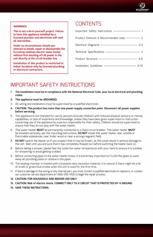
WARNINGS
This is not a do-it-yourself project. Failure to have this appliance installed by a licensed plumber and electrician will void all warranties.
Under no circumstances should you attempt to install, repair or disassemble the Eccotemp tankless electric water heater without first shutting off all power to the unit directly at the circuit breaker box.
Installation of this product is restricted to indoor locations only by licensed plumbing or electrical contractors.
CONTENTSImportant Safety Instructions ----------------------------- 1
Product Features & Recommended Uses --------------- 2
Electrical Diagrams --------------------------------------- 2-3
Technical Specifications ------------------------------------ 4
Product Structure ----------------------------------------- 4-6
Installation Guidelines ---------------------------------- 6-10
Phone: 866-356-1992 | Email: [email protected] | Address: 315 - A Industrial RD Summerville, SC 29483
2 Product Support: Eccotemp.com/help-desk Shop Online: Eccotemp.com/products Store Locater: Eccotemp.com/locater
PLEASE NOTE: THIS MANUAL IS SUBJECT TO CHANGE AT ANYTIME, TO ENSURE THIS MANUAL IS UP TO DATE PLEASE VISIT OUR HELP DESKAT WWW.ECCOTEMP.COM FOR ALL OF OUR PRODUCT MANUALS.
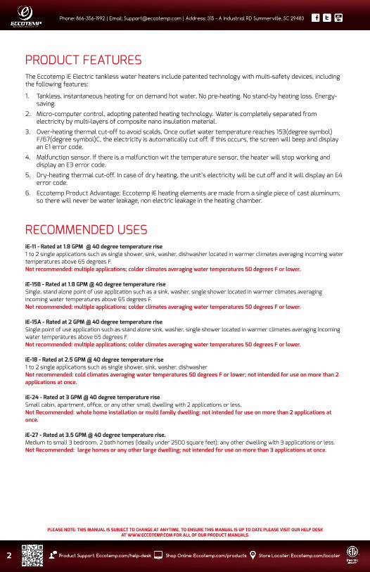
PRODUCT FEATURESThe Eccotemp iE Electric tankless water heaters include patented technology with multi-safety devices, including the following features:
1. Tankless, instantaneous heating for on demand hot water, No pre-heating. No stand-by heating loss. Energy-saving.
2. Micro-computer control, adopting patented heating technology. Water is completely separated from electricity by multi-layers of composite nano insulation material.
3. Over-heating thermal cut-off to avoid scalds. Once outlet water temperature reaches 153(degree symbol)F/67(degree symbol)C, the electricity is automatically cut off. If this occurs, the screen will beep and display an E1 error code.
4. Malfunction sensor. If there is a malfunction wit the temperature sensor, the heater will stop working and display an E3 error code.
5. Dry-heating thermal cut-off. In case of dry heating, the unit’s electricity will be cut off and it will display an E4 error code.
6. Eccotemp Product Advantage: Eccotemp iE heating elements are made from a single piece of cast aluminum; so there will never be water leakage, non electric leakage in the heating chamber.
RECOMMENDED USESiE-11 - Rated at 1.8 GPM @ 40 degree temperature rise 1 to 2 single applications such as single shower, sink, washer, dishwasher located in warmer climates averaging incoming water temperatures above 65 degrees F. Not recommended: multiple applications; colder climates averaging water temperatures 50 degrees F or lower.
iE-15B - Rated at 1.8 GPM @ 40 degree temperature rise Single, stand alone point of use application such as a sink, washer, single shower located in warmer climates averaging incoming water temperatures above 65 degrees F.Not recommended: multiple applications; colder climates averaging water temperatures 50 degrees F or lower.
iE-15A - Rated at 2 GPM @ 40 degree temperature riseSingle point of use application such as stand alone sink, washer, single shower located in warmer climates averaging incoming water temperatures above 65 degrees F.Not recommended: multiple applications; colder climates averaging water temperatures 50 degrees F or lower.
iE-18 - Rated at 2.5 GPM @ 40 degree temperature rise1 to 2 single applications such as single shower, sink, washer, dishwasherNot recommended: cold climates averaging water temperatures 50 degrees F or lower; not intended for use on more than 2 applications at once.
iE-24 - Rated at 3 GPM @ 40 degree temperature riseSmall cabin, apartment, office, or any other small dwelling with 2 applications or less.Not Recommended: whole home installation or multi family dwelling; not intended for use on more than 2 applications at once.
iE-27 - Rated at 3.5 GPM @ 40 degree temperature rise.Medium to small 3 bedroom, 2 bath homes (ideally under 2500 square feet); any other dwelling with 3 applications or less.Not Recommended: large homes or any other large dwelling; not intended for use on more than 3 applications at once.
Phone: 866-356-1992 | Email: [email protected] | Address: 315 - A Industrial RD Summerville, SC 29483
PLEASE NOTE: THIS MANUAL IS SUBJECT TO CHANGE AT ANYTIME, TO ENSURE THIS MANUAL IS UP TO DATE PLEASE VISIT OUR HELP DESKAT WWW.ECCOTEMP.COM FOR ALL OF OUR PRODUCT MANUALS.
3Product Support: Eccotemp.com/help-desk Shop Online: Eccotemp.com/products Store Locater: Eccotemp.com/locater
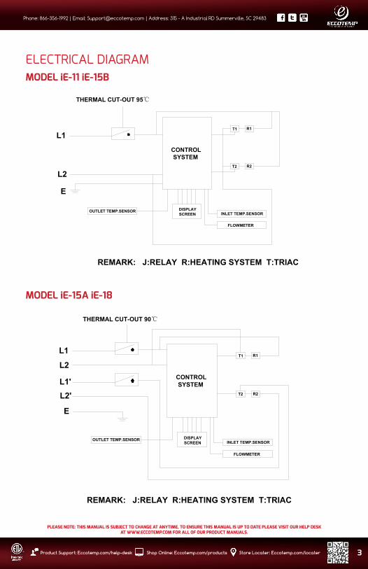
ELECTRICAL DIAGRAMMODEL iE-11 iE-15B
L1T1
T2
R1
R2
L2
E
THERMAL CUT-OUT 95℃
CONTROL SYSTEM
DISPLAYSCREEN INLET TEMP.SENSOR
FLOWMETER
OUTLET TEMP.SENSOR
REMARK: J:RELAY R:HEATING SYSTEM T:TRIAC
MODEL iE-15A iE-18
L1
L1'
T1
T2
R1
R2
L2
E
THERMAL CUT-OUT 90℃
CONTROL SYSTEM
DISPLAYSCREEN INLET TEMP.SENSOR
FLOWMETER
OUTLET TEMP.SENSOR
REMARK: J:RELAY R:HEATING SYSTEM T:TRIAC
L2'

Phone: 866-356-1992 | Email: [email protected] | Address: 315 - A Industrial RD Summerville, SC 29483
4 Product Support: Eccotemp.com/help-desk Shop Online: Eccotemp.com/products Store Locater: Eccotemp.com/locater
PLEASE NOTE: THIS MANUAL IS SUBJECT TO CHANGE AT ANYTIME, TO ENSURE THIS MANUAL IS UP TO DATE PLEASE VISIT OUR HELP DESKAT WWW.ECCOTEMP.COM FOR ALL OF OUR PRODUCT MANUALS.
TECHNICAL DATAModel iE-11 iE-15B iE-15A iE-18 iE-21 iE-24 iE-27
Phase 1 1 1 1 1 1 1
Voltage V 240 240 240 240 240 240 240
Wattage kW 11 15 15 18 21 24 27
Max. Amp. Load A 50 63 63 75 88 100 113
Min. Required Circuit Breaker A 60 80 2 X 40 2x50 3 X 40 3 X 40 3 X 50
Min. Wire Size AWG Cooper 8 6 2 X 8 2 X 8 3 X 8 3 X 8 3 X 8
Min. Water Flow To Activate GPM / L/min.
0.53 / 2 0.85 / 3.2 0.85 / 3.2 0.85 / 3.2 0.85 / 3.2 0.85 / 3.2
Weight lbs. 7 11 11 11 12 12 12
Product Dimensions Inches 17.3x10.9x3.5
Water Connections NPT 1/2” 3/4” 3/4” 3/4” 3/4” 3/4” 3/4”
Note: *suitable recognized strain relief means shall be provided when the product installed.
ELECTRICAL DIAGRAM CONTINUES...MODEL iE-21 iE-24 iE-27
L1
L1'
L1"
T1
T2
T3
R1
R2
R3L2"E
THERMAL CUT-OUT 90℃
CONTROL SYSTEM
DISPLAYSCREEN INLET TEMP.SENSOR
FLOWMETER
OUTLET TEMP.SENSOR
REMARK: J:RELAY R:HEATING SYSTEM T:TRIAC
L2
L2'

Phone: 866-356-1992 | Email: [email protected] | Address: 315 - A Industrial RD Summerville, SC 29483
PLEASE NOTE: THIS MANUAL IS SUBJECT TO CHANGE AT ANYTIME, TO ENSURE THIS MANUAL IS UP TO DATE PLEASE VISIT OUR HELP DESKAT WWW.ECCOTEMP.COM FOR ALL OF OUR PRODUCT MANUALS.
5Product Support: Eccotemp.com/help-desk Shop Online: Eccotemp.com/products Store Locater: Eccotemp.com/locater
MODEL iE-11
MODEL iE-15B
PRODUCT INNER STRUCTURE
Display screen
heating chamber
Temp.sensor
bottom case
control board
Display screen
Terminal blocksflowmeter
10.9 in.
17.3
in.
10.9 in.
17.3
in.
Display screen
heating chamber
Temp.sensor
bottom case
control board
Display screen
Terminal blocksflowmeter
10.9 in.
17.3
in.
MODEL iE-15A iE-18

Phone: 866-356-1992 | Email: [email protected] | Address: 315 - A Industrial RD Summerville, SC 29483
6 Product Support: Eccotemp.com/help-desk Shop Online: Eccotemp.com/products Store Locater: Eccotemp.com/locater
PLEASE NOTE: THIS MANUAL IS SUBJECT TO CHANGE AT ANYTIME, TO ENSURE THIS MANUAL IS UP TO DATE PLEASE VISIT OUR HELP DESKAT WWW.ECCOTEMP.COM FOR ALL OF OUR PRODUCT MANUALS.
INSTALLATION GUIDELINENOTE: The installation must be in compliance with the National Electrical Code, your local electrical and plumbing codes.
1. DO NOT install water heater near tinder, volatile or flammable substances, or near a strong magnetic field. The unit must only be mounted in a VERTICAL position near the water fittings.
2. Do not install the unit in a room where there is a chance of freezing.
3. Mount the unit to a flat section of wall, well away from any potential water splashes or spray. Be sure to use wall anchors, or screw directly into studs.
4. Position the unit upright with all plumbing connections at the bottom of the unit.
1. Make sure the appliance is intact, and all fittings are complete.
2. Please make sure the main power supply, water pressure, grounding condition, amp meter and wire meet all standards of installation requirement.
3. The water heater must be connected to a properly-grounded, dedicated branch circuit with the proper voltage rating. The ground must be connected to the “ground bar” at the circuit breaker panel.
4. This water heater MUST be permanently connected to fixed and dedicated circuit breakers. If the heater will be unused, switch off the circuit breakers.
5. When installing new unit please connect water fittings and turn water on so water flows through unit before turning POWER ON
PRODUCT INNER STRUCTURE CONTINUES...MODEL iE-21 iE-24 iE-27
Display screen
Temp.sensor
bottom case
control board
Display screen
flowmeter
heating chamber
Terminal blocks
10.9 in.
17.3
in.

Phone: 866-356-1992 | Email: [email protected] | Address: 315 - A Industrial RD Summerville, SC 29483
PLEASE NOTE: THIS MANUAL IS SUBJECT TO CHANGE AT ANYTIME, TO ENSURE THIS MANUAL IS UP TO DATE PLEASE VISIT OUR HELP DESKAT WWW.ECCOTEMP.COM FOR ALL OF OUR PRODUCT MANUALS.
7Product Support: Eccotemp.com/help-desk Shop Online: Eccotemp.com/products Store Locater: Eccotemp.com/locater
INSTALLATION LOCATION & METHODFixed installation on the wallLocate an appropriate place on a section of wall that meets all safety and installation requirements
Fig 1 Front and back of the appliance
Fig 2 Remove screw which fixed the bracket on back of the appliance.
Fig 3 Hold the back bracket hanger in position against the wall in the desired hanging location. Check to make sure that the bracket is level. Mark the wall where the mounting holes should be located. Drill holes of 1/4” diameter in the marked locations. If you are on a stud, screw the bracket directly into the wall. If you are not on a stud, insert the plastic anchor in the hole, and secure the bracket using the screwing supplied.
1.2 in.
17.8
in.
2.5 in.
1.2 in.2.5 in.

Phone: 866-356-1992 | Email: [email protected] | Address: 315 - A Industrial RD Summerville, SC 29483
8 Product Support: Eccotemp.com/help-desk Shop Online: Eccotemp.com/products Store Locater: Eccotemp.com/locater
PLEASE NOTE: THIS MANUAL IS SUBJECT TO CHANGE AT ANYTIME, TO ENSURE THIS MANUAL IS UP TO DATE PLEASE VISIT OUR HELP DESKAT WWW.ECCOTEMP.COM FOR ALL OF OUR PRODUCT MANUALS.
INSTALLATION LOCATION & METHOD CONTINUED...Fig 4 Remove (4) screws and washers from the unit to free the front cover. Carefully lift the front cover off the unit a few inches. Disengage the ribbon cable connecting the front cover LCD panel to the main control board of the unit. Remove cover completely.
Please note: If LCD connection cable cannot be disengages, simply set the front cover aside and keep the cable connected.
Fig 5 Attach unit to mounting bracket by sliding onto tabs. Make sure the unit is properly secured to both tabs of the bracket. Install bottom, center screw to affix the unit to the bracket to complete mounting.
Phone: 866-356-1992 | Email: [email protected] | Address: 315 - A Industrial RD Summerville, SC 29483
PLEASE NOTE: THIS MANUAL IS SUBJECT TO CHANGE AT ANYTIME, TO ENSURE THIS MANUAL IS UP TO DATE PLEASE VISIT OUR HELP DESKAT WWW.ECCOTEMP.COM FOR ALL OF OUR PRODUCT MANUALS.
9Product Support: Eccotemp.com/help-desk Shop Online: Eccotemp.com/products Store Locater: Eccotemp.com/locater
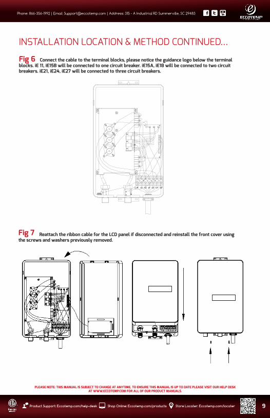
INSTALLATION LOCATION & METHOD CONTINUED...
Fig 6 Connect the cable to the terminal blocks, please notice the guidance logo below the terminal blocks. iE 11, iE15B will be connected to one circuit breaker. iE15A, iE18 will be connected to two circuit breakers. iE21, iE24, iE27 will be connected to three circuit breakers.
Fig 7 Reattach the ribbon cable for the LCD panel if disconnected and reinstall the front cover using the screws and washers previously removed.
Phone: 866-356-1992 | Email: [email protected] | Address: 315 - A Industrial RD Summerville, SC 29483
10 Product Support: Eccotemp.com/help-desk Shop Online: Eccotemp.com/products Store Locater: Eccotemp.com/locater
PLEASE NOTE: THIS MANUAL IS SUBJECT TO CHANGE AT ANYTIME, TO ENSURE THIS MANUAL IS UP TO DATE PLEASE VISIT OUR HELP DESKAT WWW.ECCOTEMP.COM FOR ALL OF OUR PRODUCT MANUALS.
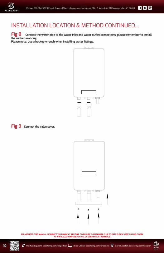
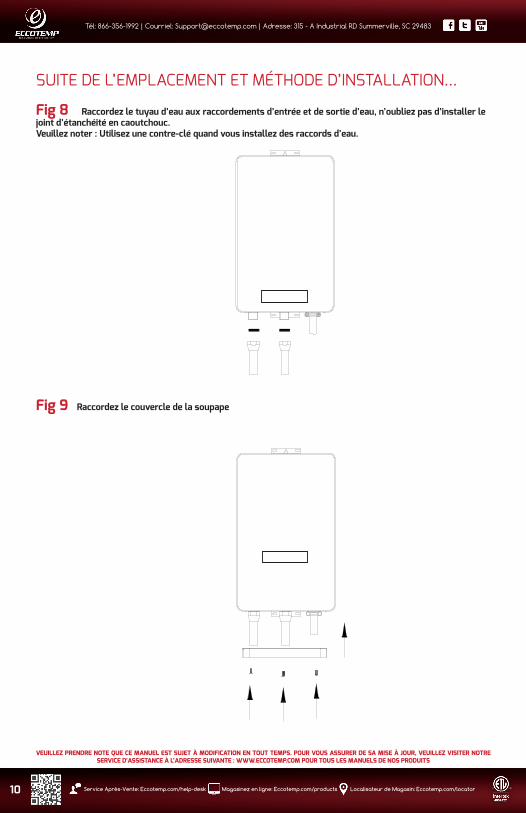
INSTALLATION LOCATION & METHOD CONTINUED...Fig 8 Connect the water pipe to the water inlet and water outlet connections, please remember to install the rubber seal ring.Please note: Use a backup wrench when installing water fittings.
Fig 9 Connect the valve cover.

Phone: 866-356-1992 | Email: [email protected] | Address: 315 - A Industrial RD Summerville, SC 29483
PLEASE NOTE: THIS MANUAL IS SUBJECT TO CHANGE AT ANYTIME, TO ENSURE THIS MANUAL IS UP TO DATE PLEASE VISIT OUR HELP DESKAT WWW.ECCOTEMP.COM FOR ALL OF OUR PRODUCT MANUALS.
11Product Support: Eccotemp.com/help-desk Shop Online: Eccotemp.com/products Store Locater: Eccotemp.com/locater
Water connections1. All water pipe must comply with national and applicable state and local water pipe codes.2. The unit should be connected directly to the main water supply. Flush pipe with water to remove any debris or loose
particles 3. It is required that 1/2”NPT water connections be used with model IE11, use 3/4”NPT water connections with the
following models, IE15A, IE15B, IE18, IE21, IE24, IE27. 4. Please remember to install rubber seal rings at the connections. When all water connections are completed, check for
leaks and take corrective action before proceeding.5. Connect the cold water supply to the threaded pope labeled :inlet” and the hot water to the threaded pipe labeled
“outlet”. IMPORTANT: RUBBER WASHER MUST BE USED FOR PROPER SEAL.
Electrical connection1. All electrical work must comply with national and applicable state and local electrical codes2. All units must be connected to a properly grounded dedicated branch circuit of proper voltage rating. 3. Before beginning any work on the electric installation, be sure that main breaker panel switch is OFF to avoid any
danger of electric shock, all mounting and plumbing must be completed before proceeding with electrical hook-up. 4. iE11, iE15B can be connected to a single circuit, use a supply cable protected by a double pole breaker. Connect the cold
water supply to the threaded pope labeled :inlet” and the hot water to the threaded pipe labeled “outlet”. IMPORTANT: RUBBER WASHER MUST BE USED FOR PROPER SEAL.
5. iE15A, iE18 require two independent circuits. Use two supply cables protected by two separate double pole breakers.6. iE21, iE24, iE27 require three independent circuits. Use three supply cables protected by three separate double pole
breakers.7. While feeding the cable to terminal blocks, please make sure the metal wire ends and the terminal blocks touch
completely. Then tighten the screws to make sure there is full contact and the current can go through.
OPERATION INSTRUCTIONS1. Turn on the circuit breaker to bring electrical power to the unit. 2. Open water faucet for a few minutes until water flow is continuous and all air is purged from water pipes. The
unit must be operated after the breakers are turned on.3. After the unit is supplied with power, a beep sound can be heard and LED lights for 2 seconds, no other display,
the appliance keeps standby.4. Touch to turn ON/OFF the appliance. When the unit is ON, LED displays actual water temperature of the
outlet. When the appliance is not operating, the screen will switch to the screen saver after 15 seconds. The display screen light will be off. Touch the screen, it will return to operating mode. Touch and to adjust the outlet temperature. Temperature setting range is 86-127°F. • If the unit has been paused, You may initially get a short burst of very hot water while you turn on again. Please run the water through for a few seconds to let the temperature settle down. Please check hot water with hand before you taking a shower.
• If the unit will not be used in winter, drain out water completely so that the heater will not FREEZE.• Please periodically clean inlet strainer and the shower to keep a free water flow.
5. Touch and hold on for 5 seconds to lock the operation keys and the will light in the display screen. All the operational keys can not function. Touch key and hold on for 5 seconds to lift the temperature lock and the will disappear in the display screen. The operational keys can function right now.
6. The real time water flow (GPM) displays in the screen when there is water flow through the water heater. 7. There is a automatic memory function to avoid repetitive operation, while you turn on the appliance, the default
set temperature will be the same as last time it was set.
4.

Phone: 866-356-1992 | Email: [email protected] | Address: 315 - A Industrial RD Summerville, SC 29483
12 Product Support: Eccotemp.com/help-desk Shop Online: Eccotemp.com/products Store Locater: Eccotemp.com/locater
PLEASE NOTE: THIS MANUAL IS SUBJECT TO CHANGE AT ANYTIME, TO ENSURE THIS MANUAL IS UP TO DATE PLEASE VISIT OUR HELP DESKAT WWW.ECCOTEMP.COM FOR ALL OF OUR PRODUCT MANUALS.
TROUBLE-SHOOTINGProblems Possible Causes Corrective Actions
1. Inlet and outlet fittings leaking A. Fittings are not tightB. Rubber washer worn-out
A. Tighten fittings.B. Change rubber washer.
2. No LED signal A. Power not connected.B. LED damaged.
A. Connect power to the unit.B. Change LED.
3. Functional keys not working A. No water out from shower.B. Water pressure too low.C. Key or PCB damaged.
A. Open valve to get water.B. Open valve to get pressure.C. Change key or PCB.
4. Water too hot A. Too high temperature set.B. Water flow too little.
A. Set a lower temperature.B. Open valve more.
5. Water too cold A. Low temperature set.B. Water flow too much.
A. Set a higher temperature.B. Reduce water flow.
6. Reduced outlet water pressure Inlet strainer or shower clogged. Clean strainer and shower.
7. LED displays E1 Outlet temperature is over 67°F/153°F A, Reduce the temperatureB, Turn up the water flow
8. LED displays E3 Temperature sensor failure Please contact with your local dealer
9. Display overload Inlet water flow is too high. Reduce the inlet water flow
7 and 8 should only be performed by qualified electrician. The person who initially installed the unit is the best one to contact for help.
NORMAL MAINTENANCENote: Do not attempt to repair this water heater yourself. Call a service person for assistance. Always turn off all power supply to the unit. Turn off all circuit breakers supplying power to the appliance *please note some units are connected multiple circuit breakers. Turn OFF ALL WATER SUPPLY and ALL POWER SUPPLY.
This unit does not require any regular maintenance. However, to ensure consistent water flow, it is recommended to follow the following procedures.
1. Periodically remove scale and dirt that may build up at the aerator of the faucet or in the shower head. 2. There is a built in filter screen at inlet connection which should be cleaned from time to time. Please turn off the water flow before doing this.
EXPLOSIVE VIEW

Phone: 866-356-1992 | Email: [email protected] | Address: 315 - A Industrial RD Summerville, SC 29483
PLEASE NOTE: THIS MANUAL IS SUBJECT TO CHANGE AT ANYTIME, TO ENSURE THIS MANUAL IS UP TO DATE PLEASE VISIT OUR HELP DESKAT WWW.ECCOTEMP.COM FOR ALL OF OUR PRODUCT MANUALS.
13Product Support: Eccotemp.com/help-desk Shop Online: Eccotemp.com/products Store Locater: Eccotemp.com/locater
Eccotemp Systems ,LLCLimited Warranty InformationMODELS: iE-11 iE-15B iE-15A iE-18 iE-24 iE-27
Eccotemp hereby warrants this product to be free of material defects in materials and workmanship when installed and operated according to Eccotemp’s installation and operating instructions. This Limited Warranty extends to the original purchaser and subsequent owners, but only while the product remains as the site of the original installation. This Limited Warranty terminates if moved or reinstalled at a new location. There are no warranties, express or implied made or given other than contained in this Limited Warranty. No agent, employee or representative of Eccotemp has any authority to bind Eccotemp to any representation or warranty concerning the Product not contained in this Limited Warranty. Eccotemp reserves the right and authority to change, modify or alter this warranty at any given time.
Except as expressly set forth herein, THERE ARE NO REPRESENTATIONS OR WARRANTIES, EXPRESS OR IMPLIED, INCLUDING, WITHOUT LIMITATION, AS TO MERCHANTABILITY OR FITNESS FOR A PARTICULAR PURPOSE WITH RESPECT TO ANY GOODS SOLD HEREUNDER. BUYER’S EXCLUSIVE REMEDY IS LIMITED TO REPAIR OR REPLACEMENT OF THE GOODS SOLD, AT ECCOTEMP’S DISCRETION. ECCOTEMP SHALL NOT BE LIABLE FOR INCIDENTAL OR CONSEQUENTIAL DAMAGES.
Limited Warranty Period
This Warranty is extended by Eccotemp Systems to the Owner. This warranty takes effect on the date of installation of the Product or 30 days after the date of purchase, whichever occurs first, and is effective until the specified anniversary of such date as follows:
Item Period of Coverage
Heating Chamber/Element 3 yearsAll other parts 2 years
Coverage’s are void if the unit is used in a hot water circulation loop, in series with a circulation system or where an on-demand recirculation system is not incorporated.
Owner is responsible for all other costs incidental to repair such as labor, shipping, delivery and permits.Proof of purchase required. Products repaired will be covered under this Limited Warranty for the remainder of term of the original purchase.
Exclusions
Please refer to the Installation Manual and Use & Care Manual supplied with your new Eccotemp Systems product. This Limited Warranty becomes null and void if any of the following are determined to be a contributing factor by Eccotemp to the failure of the product:
1. Abuse, misuse, alteration, neglect or misapplication.2. Improper, dangerous, destructive maintenance procedures or inadequate maintenance.3. Damages caused by services performed by servicers other than Eccotemp Systems.4. Installation in a corrosive or otherwise destructive environment.5. Damage as a result of freezing within the unit or surrounding piping.6. Scale buildup.7. Incorrect voltage, amps or water pressure .8. Acts of force Majeure.9. Damage as a result of use with non-portable, untreated or poorly treated well water, or water with high PH levels or
hardness levels in excess of 12 grains per gallon (200mg/L).10. Incorrect sizing for the application.11. Products with original serial numbers that have been removed or altered and cannot be readily determined.12. Acts of God including, but not limited to; fire, flood, or nature disaster.

Phone: 866-356-1992 | Email: [email protected] | Address: 315 - A Industrial RD Summerville, SC 29483
14 Product Support: Eccotemp.com/help-desk Shop Online: Eccotemp.com/products Store Locater: Eccotemp.com/locater
PLEASE NOTE: THIS MANUAL IS SUBJECT TO CHANGE AT ANYTIME, TO ENSURE THIS MANUAL IS UP TO DATE PLEASE VISIT OUR HELP DESKAT WWW.ECCOTEMP.COM FOR ALL OF OUR PRODUCT MANUALS.
This Product is not to be used as a pool or spa heater.
In the event of an Eccotemp Systems recognized defect, malfunction, or failure to conform to this Warranty and based upon Eccotemp approval of warranty claim, Eccotemp Systems, at its sole and absolute discretion, will settle the warrant claim of such defect, malfunction, or failure to conform to this Warranty. In order to make a claim under this Warranty, The Owner must notify Eccotemp of the failure of the Product to conform to this Warranty.
Under this Warranty, Eccotemp Systems will only provide replacement parts as described in the “Limited WarrantyPeriod”. The Owner will be responsible for any cost incurred including labor costs for servicing the unit, shipping, delivery, and handling of the replacement part, cost for permits or materials necessary for the repair, or incidental costs resulting from damage external to the unit resulting from the failure.
NOTWITHSTANDING ANYTHING IN THIS WARRANTY TO THE CONTRARY, EXCEPT FOR ECCOTEMP SYSTEMS’ AFFIRMATIVE OBLIGATIONS EXPRESSLY SET FORTH IN THIS WARRANTY, ECCOTEMP SYSTEMS DISCLAIMS ANY AND ALL WARRANTIES, EITHER EXPRESS OR IMPLIED, REGARDING THE PRODUCT AND ITS FUNCTIONALITY, PERFORMANCE, MERCHANTABILITY, FITNESS FOR PARTICULAR PURPOSE OR INTELLECTUAL PROPERTY RIGHTS. ECCOTEMP SYSTEMS DISCLAIMS ALL OTHER OBLIGATIONS OR LIABILITIES ON ITS PART AND NEITHER ASSUMES NOR AUTHORIZES ANY OTHER PERSON TO ASSUME FOR ECCOTEMP SYSTEMS AN OTHER LIABILITIES IN CONNECTION WITH THE PERFORMANCE OF THE PRODUCT. THIS WARRANTY ONLY COVERS REPLACEMENT PARTS AND DOES NOT COVER COST OF LABOR OR SERVICES UNDER ANY CIRCUMSTANCES.
Systems by any other part for damages of any kind, including, but not limited to incidental and consequential damages, arising out of the subject matter of this Agreement. Some States do not allow exclusion or limitation of incidental or consequential damages, so the above limitation or exclusion may not apply to you. This warranty gives you specific legal rights. You may also have other rights that vary from State to State.
CHECK OUT SOME OF OUR OTHER ECCOTEMP PRODUCTSWHOLE HOME PRODUCT COMPARISONS

Phone: 866-356-1992 | Email: [email protected] | Address: 315 - A Industrial RD Summerville, SC 29483
PLEASE NOTE: THIS MANUAL IS SUBJECT TO CHANGE AT ANYTIME, TO ENSURE THIS MANUAL IS UP TO DATE PLEASE VISIT OUR HELP DESKAT WWW.ECCOTEMP.COM FOR ALL OF OUR PRODUCT MANUALS.
15Product Support: Eccotemp.com/help-desk Shop Online: Eccotemp.com/products Store Locater: Eccotemp.com/locater
BTU
Flow Rate
Portable
Power Source
Gas Type
Venting
Water Pressure
Regulator & Hose
Temperature Control
Warranty
Product Dimensions
Package Dimensions
INSTALLATION
i12fvi12
INDOOR ONLY
74,000
3.6 GPM
No
120 VAC
Available in NG & LP
2.5” horizontal Venting (Incl)
20-80 PSI
Not Included
Manual 80” - 120”
2 Years limited
15” x 4” x 24” - 30 lbs
17” x 11” x 28” - 32 lbs
CHECK OUT SOME OF OUR OTHER ECCOTEMP PRODUCTSWHOLE HOME PRODUCT COMPARISONS
fvi12
INDOOR ONLY
80,000
3 GPM
No
120 VAC
Available in NG & LP
2.5” horizontal Venting (Incl)
20-80 PSI - Flow activated
Not Included
Automatic 80° - 120°
2 Years limited
14” x 5” x 24” - 30 lbs
17” x 11” x 29” - 32 lbs
i12
OUTDOOR ONLY
140,000
6.8 GPM
No
120 VAC
Available in NG & LP
Not Needed
20-80 PSI - Flow Activated
Not included
Automatic 90° - 140°
10 Years - Heat Exchanger5 Years - Parts
15” x 5” x 24” - 38 lbs
16” x 7.5” x 26” - 40 lbs
45-H
INDOOR ONLY
140,000
6.8 GPM
No
120 VAC
Available in NG & LP
Sold Separately
20-80 PSI - Flow Activated
Not Included
Automatic 90° - 140°
10 Years - Heat Exchanger5 Years - Parts
15” x 5” x 24” - 38 lbs
16” x 7.5” x 26” - 40 lbs
45-HI
45-H 45-HI

Phone: 866-356-1992 | Email: [email protected] | Address: 315 - A Industrial RD Summerville, SC 29483
Product Support: Eccotemp.com/help-desk Shop Online: Eccotemp.com/products Store Locater: Eccotemp.com/locater
PLEASE NOTE: THIS MANUAL IS SUBJECT TO CHANGE AT ANYTIME, TO ENSURE THIS MANUAL IS UP TO DATE PLEASE VISIT OUR HELP DESKAT WWW.ECCOTEMP.COM FOR ALL OF OUR PRODUCT MANUALS.


Tél: 866-356-1992 | Courriel: [email protected] | Adresse: 315 - A Industrial RD Summerville, SC 29483
Service Après-Vente: Eccotemp.com/help-desk Magasinez en ligne: Eccotemp.com/products Localisateur de Magasin: Eccotemp.com/locator
VEUILLEZ PRENDRE NOTE QUE CE MANUEL EST SUJET À MODIFICATION EN TOUT TEMPS. POUR VOUS ASSURER DE SA MISE À JOUR, VEUILLEZ VISITER NOTRE SERVICE D’ASSISTANCE À L’ADRESSE SUIVANTE : WWW.ECCOTEMP.COM POUR TOUS LES MANUELS DE NOS PRODUITS

VEUILLEZ PRENDRE NOTE QUE CE MANUEL EST SUJET À MODIFICATION EN TOUT TEMPS. POUR VOUS ASSURER DE SA MISE À JOUR, VEUILLEZ VISITER NOTRE SERVICE D’ASSISTANCE À L’ADRESSE SUIVANTE : WWW.ECCOTEMP.COM POUR TOUS LES MANUELS DE NOS PRODUITS
Tél: 866-356-1992 | Courriel: [email protected] | Adresse: 315 - A Industrial RD Summerville, SC 29483
Service Après-Vente: Eccotemp.com/help-desk Magasinez en ligne: Eccotemp.com/products Localisateur de Magasin: Eccotemp.com/locator
Eccotemp Systems, LLC315-A Industrial Road
Summerville, SC 29483866-356-1992
RISQUE DE CHOCÉLECTRIQUEICA
CHAUFFE-EAU ÉLECTRIQUE SANS RÉSERVOIR
4002422
MODEL #:
iE-11CAPACITÉ : 240Vac, 60Hz, 11000W
CAPACITÉ DEDÉBIT : 0.85-3.2 GPM
CAPACITÉ DU DISJONCTEUR REQUISE:60A
CONFORME À UL STD 499CERTIFIÉ NORME CSA STD. C22.2 No.64-10
NUMÉRO DE SÉRIE :
FABRIQUÉ EN CHINE
DANGER & AVERTISSEMENT :
POUR USAGE DOMESTIQUE ET
INTÉRIEUR SEULEMENT
Eccotemp Systems, LLC315-A Industrial Road
Summerville, SC 29483866-356-1992
RISQUE DE CHOCÉLECTRIQUEICA
CHAUFFE-EAU ÉLECTRIQUE SANS RÉSERVOIR
4002422
MODEL #:
iE-15BCAPACITÉ : 240Vac, 60Hz, 15000W
CAPACITÉ DEDÉBIT : 0.85-3.2 GPM
CAPACITÉ DU DISJONCTEUR REQUISE:80A
CONFORME À UL STD 499CERTIFIÉ NORME CSA STD. C22.2 No.64-10
NUMÉRO DE SÉRIE :
FABRIQUÉ EN CHINE
DANGER & AVERTISSEMENT :
POUR USAGE DOMESTIQUE ET
INTÉRIEUR SEULEMENT
Eccotemp Systems, LLC315-A Industrial Road
Summerville, SC 29483866-356-1992
RISQUE DE CHOCÉLECTRIQUEICA
CHAUFFE-EAU ÉLECTRIQUE SANS RÉSERVOIR
4002422
MODEL #:
iE-15ACAPACITÉ : 240Vac, 60Hz, 15000W
CAPACITÉ DEDÉBIT : 0.85-3.2 GPM
CAPACITÉ DU DISJONCTEUR REQUISE:2x40A
CONFORME À UL STD 499CERTIFIÉ NORME CSA STD. C22.2 No.64-10
NUMÉRO DE SÉRIE :
FABRIQUÉ EN CHINE
DANGER & AVERTISSEMENT :
POUR USAGE DOMESTIQUE ET
INTÉRIEUR SEULEMENT
Eccotemp Systems, LLC315-A Industrial Road
Summerville, SC 29483866-356-1992
RISQUE DE CHOCÉLECTRIQUEICA
CHAUFFE-EAU ÉLECTRIQUE SANS RÉSERVOIR
4002422
MODEL #:
iE-18CAPACITÉ : 240Vac, 60Hz, 18000W
CAPACITÉ DEDÉBIT : 0.85-4.2 GPM
CAPACITÉ DU DISJONCTEUR REQUISE:2x50A
CONFORME À UL STD 499CERTIFIÉ NORME CSA STD. C22.2 No.64-10
NUMÉRO DE SÉRIE :
FABRIQUÉ EN CHINE
DANGER & AVERTISSEMENT :
POUR USAGE DOMESTIQUE ET
INTÉRIEUR SEULEMENT
Eccotemp Systems, LLC315-A Industrial Road
Summerville, SC 29483866-356-1992
RISQUE DE CHOCÉLECTRIQUEICA
CHAUFFE-EAU ÉLECTRIQUE SANS RÉSERVOIR
4002422
MODEL #:
iE-24CAPACITÉ : 240Vac, 60Hz, 24000W
CAPACITÉ DEDÉBIT : 0.85-6 GPM
CAPACITÉ DU DISJONCTEUR REQUISE:3x40A
CONFORME À UL STD 499CERTIFIÉ NORME CSA STD. C22.2 No.64-10
NUMÉRO DE SÉRIE :
FABRIQUÉ EN CHINE
DANGER & AVERTISSEMENT :
POUR USAGE DOMESTIQUE ET
INTÉRIEUR SEULEMENT
Eccotemp Systems, LLC315-A Industrial Road
Summerville, SC 29483866-356-1992
CHAUFFE-EAU ÉLECTRIQUE SANS RÉSERVOIR
4002422
MODEL #:
iE-27CAPACITÉ : 240Vac, 60Hz, 27000W
CAPACITÉ DEDÉBIT : 0.85-6 GPM
CAPACITÉ DU DISJONCTEUR REQUISE:3x50A
CONFORME À UL STD 499CERTIFIÉ NORME CSA STD. C22.2 No.64-10
NUMÉRO DE SÉRIE :
FABRIQUÉ EN CHINE
DANGER & AVERTISSEMENT :
POUR USAGE DOMESTIQUE ET
INTÉRIEUR SEULEMENT
RISQUE DE CHOCÉLECTRIQUEICA
Tél: 866-356-1992 | Courriel: [email protected] | Adresse: 315 - A Industrial RD Summerville, SC 29483
Service Après-Vente: Eccotemp.com/help-desk Magasinez en ligne: Eccotemp.com/products Localisateur de Magasin: Eccotemp.com/locator
VEUILLEZ PRENDRE NOTE QUE CE MANUEL EST SUJET À MODIFICATION EN TOUT TEMPS. POUR VOUS ASSURER DE SA MISE À JOUR, VEUILLEZ VISITER NOTRE SERVICE D’ASSISTANCE À L’ADRESSE SUIVANTE : WWW.ECCOTEMP.COM POUR TOUS LES MANUELS DE NOS PRODUITS
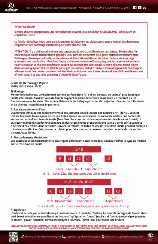
AVERTISSEMENT
Si votre chauffe-eau nécessite une réinitialisation, assurez-vous d’ÉTEINDRE LES DISJONCTEURS avant de réinitialiser l’unité.
Le fait de réinitialiser votre unité sans éteindre préalablement les disjoncteurs peut entraîner des dommages corporels et des dommages matériels pour votre chauffe-eau.
ATTENTION ! Il y a de l’eau à l’intérieur des serpentins de votre chauffe-eau en tout temps. Si votre chauffe-eau est exposé à des températures glaciales, l’eau dans les serpentins peut geler, causant une rupture dans l’échangeur thermique de l’unité, ou dans les conduites d’alimentation et de retour. Ce type de dommage entraînera une coulée d’eau libre dans l’espace où se trouve le chauffe-eau, risquant de causer une inondation. NE PAS installer ce chauffe-eau dans un espace qui pourrait être sujet au gel. Si votre chauffe-eau se trouve dans une aire qui pourrait être atteinte par le gel, vous devez éteindre l’arrivée d’eau à l’appareil de chauffage et vidanger toute l’eau en fermant les conduites d’alimentation en eau. Laissez les conduites d’alimentation en eau à l’arrêt jusqu’à ce que vous prévoyiez d’utiliser le chauffe-eau.
Guide de Démarrage RapideiE-18 | iE-21 | iE-24 | iE-27
1) MontageMonter le chauffe-eau verticalement sur une surface plate (c’-à-d. un panneau ou un mur) plus large que l’unité elle-même. Assurez-vous de fixer le support de façon sécuritaire en utilisant un montant ou les fixations murales fournies. Placer-le à distance de tout risque potentiel de projection d’eau ou de fuite d’eau, et de champs magnétiques importants.
2) Les raccordements d’eauQuand vous installez vos raccordements d’eau, assurez-vous d’utiliser des raccords NPT de ¾”. Veuillez utiliser les joints fournis pour éviter des fuites. Quand vous resserrez les raccords, utilisez une contre-clé sur les raccords d’entrée et de sortie (les côtés plats des raccords sont situés derrière le capot frontal). Il est recommandé d’installer une soupape de décharge à haute pression et une vanne d’arrêt sur la conduite d’arrivée d’eau froide, dans cet ordre. Ouvrez un robinet et faites couler de l’eau dans l’unité pendant quelques minutes pour éliminer l’air, fermer le robinet pour faire monter la pression dans la conduite afin de vérifier d’éventuelles fuites.
3) Raccordements électriques Les câbles pour les raccordements électriques diffèreront selon le modèle, veuillez vérifier le type du modèle sur le côté droit de l’unité.
4) OpérationL’unité est activée par le débit d’eau qui passe à travers la conduite d’entrée. Le point de consigne de température désirée est sélectionnée en utilisant les boutons “up” (plus) ou “down” (moins), si l’unité ne répond pas poussez le bouton “power” (marche) central et essayez à nouveau. Testez l’eau pour éviter une brûlure.
iE-18
E L1 L2 L1 L2
Terre Disjoncteur1 Disjoncteur 2iE-18 – Deux 22ov Disjoncteurs bipolaires de 50 amp
iE-21, iE-24, iE-27
E L1 L2 L1 L2
iE-21, iE-24, iE-27 – Trois 22ov Disjoncteurs bipolaires de 50 amp
L1 L2
Terre Disjoncteur1 Disjoncteur 2 Disjoncteur3
VEUILLEZ PRENDRE NOTE QUE CE MANUEL EST SUJET À MODIFICATION EN TOUT TEMPS. POUR VOUS ASSURER DE SA MISE À JOUR, VEUILLEZ VISITER NOTRE SERVICE D’ASSISTANCE À L’ADRESSE SUIVANTE : WWW.ECCOTEMP.COM POUR TOUS LES MANUELS DE NOS PRODUITS
1
Tél: 866-356-1992 | Courriel: [email protected] | Adresse: 315 - A Industrial RD Summerville, SC 29483
Service Après-Vente: Eccotemp.com/help-desk Magasinez en ligne: Eccotemp.com/products Localisateur de Magasin: Eccotemp.com/locator
INSTRUCTIONS DE SÉCURITÉ IMPORTANTES1. L’installation doit être en conformité avec le Code Électrique National, votre codes locaux concernant
l’électricité et le plombage.
2. Cet appareil doit être RACCORDÉ À LA TERRE.
3. Tout câblage et installation doit être supervisé par un électricien qualifié.
4. DANGER: Ce produit a plus d’un point de raccordement à l’alimentation électrique. Débranchez toutes les sources d’alimentation électrique avant une maintenance.
5. Cet appareil ne doit pas être utilisé par des personnes (ce qui inclut les enfants) ayant des capacités sensorielles physiques ou mentales réduites, ou un manque d’expérience et de connaissance, à moins qu’ils n’aient reçu une supervision ou des instructions concernant l’utilisation de l’appareil par une personne responsable de leur sécurité. Les enfants doivent être supervisés pour assurer qu’ils ne jouent pas avec le chauffe-eau.
6. Ce chauffe-eau DOIT être branché de manière permanente à un disjoncteur fixe. Ce chauffe-eau DOIT être installé verticalement, en suivant les instructions de montage. NE PAS installer ce chauffe-eau à côté de substances volatiles ou inflammables, à côté de bois d’allumage ou près d’un champ magnétique important.
7. NE PAS mettre l’appareil de chauffage en fonctionnement si vous suspectez qu’il puisse être gelé, car cela pourrait provoquer des dommages importants de l’unité. Attendez jusqu’à ce que vous soyez sûr qu’il se trouve totalement dégelé avant de remettre en route l’appareil de chauffage.
8. Avant de prendre une douche, veuillez vérifier la température de la sortie d’eau chaude avec votre main, pour vous assurer que cela convient à une douche et ne pas risquer de vous brûler.
9. Avant de brancher les tuyaux aux canalisations, il est extrêmement important de VIDANGER les tuyaux de manière à évacuer tout résidu de colle de plomberie ou autre, des tuyaux.
10. La chambre de chauffe est traitée avec du matériel d’isolation nanocomposite ; il est normal qu’il puisse y avoir un peu d’odeur ou de fumée verte-bleue lors de la première utilisation.
11. S’il y a un dommage au niveau des câbles ou toute autre partie interne, vous devez contacter un électricien qualifié pour remplacer cette pièce, ou contacter notre département de service à la clientèle au 1.866-356-1992 pour commencer la procédure de réparation.
12. DANGER : POUR UN USAGE DOMESTIQUE EN INTÉRIEUR UNIQUEMENT
13. DANGER : Risque de choc électrique. À RACCORDER UNIQUEMENT À UN CIRCUIT QUI EST PROTÉGÉ PAR UNE MISE À LA TERRE.
14. GARDEZ CES INSTRUCTIONS.
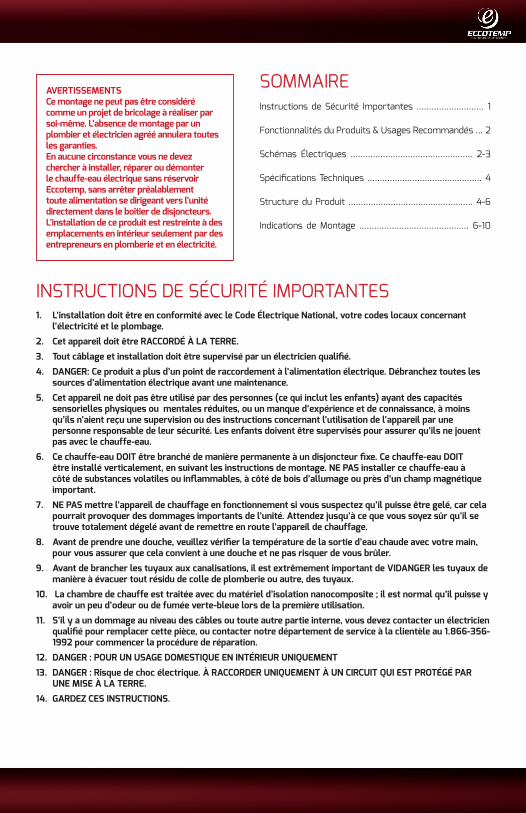
AVERTISSEMENTSCe montage ne peut pas être considéré comme un projet de bricolage à réaliser par soi-même. L’absence de montage par un plombier et électricien agréé annulera toutes les garanties.En aucune circonstance vous ne devez chercher à installer, réparer ou démonter le chauffe-eau électrique sans réservoir Eccotemp, sans arrêter préalablement toute alimentation se dirigeant vers l’unité directement dans le boîtier de disjoncteurs.L’installation de ce produit est restreinte à des emplacements en intérieur seulement par des entrepreneurs en plomberie et en électricité.
SOMMAIREInstructions de Sécurité Importantes ........................... 1
Fonctionnalités du Produits & Usages Recommandés ... 2
Schémas Électriques ................................................. 2-3
Spécifications Techniques .............................................. 4
Structure du Produit .................................................. 4-6
Indications de Montage ............................................ 6-10

Tél: 866-356-1992 | Courriel: [email protected] | Adresse: 315 - A Industrial RD Summerville, SC 29483
2 Service Après-Vente: Eccotemp.com/help-desk Magasinez en ligne: Eccotemp.com/products Localisateur de Magasin: Eccotemp.com/locator
VEUILLEZ PRENDRE NOTE QUE CE MANUEL EST SUJET À MODIFICATION EN TOUT TEMPS. POUR VOUS ASSURER DE SA MISE À JOUR, VEUILLEZ VISITER NOTRE SERVICE D’ASSISTANCE À L’ADRESSE SUIVANTE : WWW.ECCOTEMP.COM POUR TOUS LES MANUELS DE NOS PRODUITS
FONCTIONNALITÉS DU PRODUITLes chauffes-eau Électriques sans Réservoir Eccoptemp de série iE contiennent une technologie brevetée possédant de multiples dispositifs de sécurité, incluant les fonctions suivantes:
1. Un réchauffement instantané sans réservoir pour de l’eau chaude à la demande. Pas de préchauffage. Pas de perte de chaleur en dormance. Économie d’énergie.
2. Contrôle par micro-ordinateur, adoptant une technologie de chauffage brevetée. L’eau est totalement séparée de l’électricité par de multiples couches de matériel d’isolation nanocomposite.
3. Des thermocontacteurs de surchauffe pour éviter les brûlures. Une fois que la température de la sortie d’eau atteint 153⁰F/67⁰ C, l’électricité est automatiquement arrêtée. Si cela se produit, l’écran émettra un signal sonore et affichera le code d’erreur E1.
4. un capteur de dysfonctionnement. S’il y a un dysfonctionnement avec le capteur de température, le chauffe-eau s’arrêtera de fonctionner et affichera un code d’erreur E3.
5. Thermocontacteur de chauffage à sec. En cas de chauffage à sec, l’électricité de l’unité sera coupée et l’appareil affichera un code d’erreur E4.
6. Avantage du Produit Eccotemp: Les éléments de chauffage iE Eccotemp sont faits à partir d’une pièce unique en fonte d’aluminium ; il n’y aura donc jamais de fuite d’eau, ni fuite électrique dans la chambre de chauffe.
USAGES RECOMMANDÉSiE-11 – Évalué à 1.8 GPM @ 40 degrés de hausse de température 1 à 2 applications uniques comme un seul élément : douche, évier, laveuse, lave-vaisselle, situé dans des climats tempérés avec des températures d’arrivée d’eau supérieures à 65 degrés F.Non recommandé: de multiples applications ; des climats plus froids avec des températures aux alentours de 50 degrés F ou inférieures.
iE-15B – Évalué à 1.8 GPM @ 40 degrés de hausse de températureUnique, point d’utilisation pour application autonome tel qu’un évier, une laveuse, une douche unique, situé dans des climats tempérés avec des températures de l’eau au-dessus de 65 degrés F.Non recommandé: de multiples applications ; des climats plus froids avec des températures aux alentours de 50 degrés F ou inférieures.
iE-15A – Évalué à 2 GPM @ 40 degrés de hausse de température1 à 2 applications autonomes telle qu’un évier, une laveuse, une douche unique, situé dans des climats plus tempérés avoisinants les températures d’eau d’arrivée au-dessus de 65 degrés F.Non recommandé : des applications multiples ; les climats plus froids avec des moyennes de températures de 50 degrés F ou inférieures.
iE-18 – Évalué à 2.5 GPM @ 40 degrés de hausse de température1 à 2 applications telle que une douche unique, un évier, une laveuse, un lave-vaisselle.Non recommandé : des climats froids et des températures avoisinants les 50 degrés F ou inférieurs ; non destiné pour une utilisation sur plus de deux applications à la fois.
iE-24 – Évalué à 3 GPM @ 40 degrés de hausse de températurePetite cabine, appartement, bureau ou toute autre petite habitation avec deux applications ou moins.Non recommandé : une installation pour toute la maison ou pour une habitation multifamiliale; non destiné pour une utilisation sur plus de 2 applications à la fois.
iE-27 – Évalué à 3.5 GPM @ une hausse de température de 40 degrésMoyen ou Petit 3 chambres, 2 salles de bains (idéalement en-dessous de 2500 pieds carrés) ; toute autre habitation avec 3 applications ou moins.Non recommandé : De grandes maisons ou toute autre grande habitation ; non destiné pour une utilisation sur plus de 3 applications à la fois.

VEUILLEZ PRENDRE NOTE QUE CE MANUEL EST SUJET À MODIFICATION EN TOUT TEMPS. POUR VOUS ASSURER DE SA MISE À JOUR, VEUILLEZ VISITER NOTRE SERVICE D’ASSISTANCE À L’ADRESSE SUIVANTE : WWW.ECCOTEMP.COM POUR TOUS LES MANUELS DE NOS PRODUITS
3
Tél: 866-356-1992 | Courriel: [email protected] | Adresse: 315 - A Industrial RD Summerville, SC 29483
Service Après-Vente: Eccotemp.com/help-desk Magasinez en ligne: Eccotemp.com/products Localisateur de Magasin: Eccotemp.com/locator
SCHÉMAS ÉLECTRIQUESMODÈLE iE-11 iE-15B
L1T1
T2
R1
R2
L2
E
THERMAL CUT-OUT 95℃
CONTROL SYSTEM
DISPLAYSCREEN INLET TEMP.SENSOR
FLOWMETER
OUTLET TEMP.SENSOR
REMARK: J:RELAY R:HEATING SYSTEM T:TRIAC
MODÈLE iE-15A iE-18
L1
L1'
T1
T2
R1
R2
L2
E
THERMAL CUT-OUT 90℃
CONTROL SYSTEM
DISPLAYSCREEN INLET TEMP.SENSOR
FLOWMETER
OUTLET TEMP.SENSOR
REMARK: J:RELAY R:HEATING SYSTEM T:TRIAC
L2'
CAPTEUR DE TEMPÉRATURE DE SORTIE CAPTEUR DE TEMPÉRATURE D›ENTRÉE
DÉBIMÈTRE
ÉCRAN D›AFFICHAGE
SYSTÈME
DE CONTRÔLE
NOTE : J : RELAIS R : SYSTÈME DE CHAUFFAGE T : TRIAC
THERMOCONTACTEUR 95 °C
SENSORES DE TEMPERATURA DE SALIDA CAPTEUR DE TEMPÉRATURE D›ENTRÉE
DÉBIMÈTRE
ÉCRAN D›AFFICHAGE
SYSTÈME
DE CONTRÔLE
NOTE : J : RELAI R : SYSTÈME DE CHAUFFAGE T : TRIAC
THERMOCONTACTEUR 90 °C

Tél: 866-356-1992 | Courriel: [email protected] | Adresse: 315 - A Industrial RD Summerville, SC 29483
4 Service Après-Vente: Eccotemp.com/help-desk Magasinez en ligne: Eccotemp.com/products Localisateur de Magasin: Eccotemp.com/locator
VEUILLEZ PRENDRE NOTE QUE CE MANUEL EST SUJET À MODIFICATION EN TOUT TEMPS. POUR VOUS ASSURER DE SA MISE À JOUR, VEUILLEZ VISITER NOTRE SERVICE D’ASSISTANCE À L’ADRESSE SUIVANTE : WWW.ECCOTEMP.COM POUR TOUS LES MANUELS DE NOS PRODUITS
DONNÉES TECHNIQUESModèle iE-11 iE-15B iE-15A iE-18 iE-21 iE-24 iE-27
Phase 1 1 1 1 1 1 1
Voltage V 240 240 240 240 240 240 240
Puissance kW 11 15 15 18 21 24 27
Charge Max. Amp. A 50 63 63 75 88 100 113
Min. Requis Disjoncteur A 60 80 2 X 40 2x50 3 X 40 3 X 40 3 X 50
Min. Calibre Câble AWG Cooper 8 6 2 X 8 2 X 8 3 X 8 3 X 8 3 X 8
Min. Débit d’Eau Pour Activer GPM / L/min.
0.53 / 2 0.85 / 3.2 0.85 / 3.2 0.85 / 3.2 0.85 / 3.2 0.85 / 3.2
Poids en livres 7 11 11 11 12 12 12
Dimensions du Produit en Pouces 17.3x10.9x3.5
Raccords Eau NPT 1/2” 3/4” 3/4” 3/4” 3/4” 3/4” 3/4”
Note : *dispositif de décharge de traction reconnue adaptable signifie qu’il doit être fourni à l’installation du produit.
SUITE DES SCHÉMAS ÉLECTRIQUES...MODEL iE-21 iE-24 iE-27
L1
L1'
L1"
T1
T2
T3
R1
R2
R3L2"E
THERMAL CUT-OUT 90℃
CONTROL SYSTEM
DISPLAYSCREEN INLET TEMP.SENSOR
FLOWMETER
OUTLET TEMP.SENSOR
REMARK: J:RELAY R:HEATING SYSTEM T:TRIAC
L2
L2'
CAPTEUR DE TEMPÉRATURE DE SORTIECAPTEUR DE TEMPÉRATURE D›ENTRÉE
DÉBIMÈTRE
ÉCRAN D›AFFICHAGE
SYSTÈME
DE CONTRÔLE
NOTE : J : RELAI R : SYSTÈME DE CHAUFFAGE T : TRIAC
THERMOCONTACTEUR 90⁰ C
VEUILLEZ PRENDRE NOTE QUE CE MANUEL EST SUJET À MODIFICATION EN TOUT TEMPS. POUR VOUS ASSURER DE SA MISE À JOUR, VEUILLEZ VISITER NOTRE SERVICE D’ASSISTANCE À L’ADRESSE SUIVANTE : WWW.ECCOTEMP.COM POUR TOUS LES MANUELS DE NOS PRODUITS
5
Tél: 866-356-1992 | Courriel: [email protected] | Adresse: 315 - A Industrial RD Summerville, SC 29483
Service Après-Vente: Eccotemp.com/help-desk Magasinez en ligne: Eccotemp.com/products Localisateur de Magasin: Eccotemp.com/locator
Note : *dispositif de décharge de traction reconnue adaptable signifie qu’il doit être fourni à l’installation du produit.
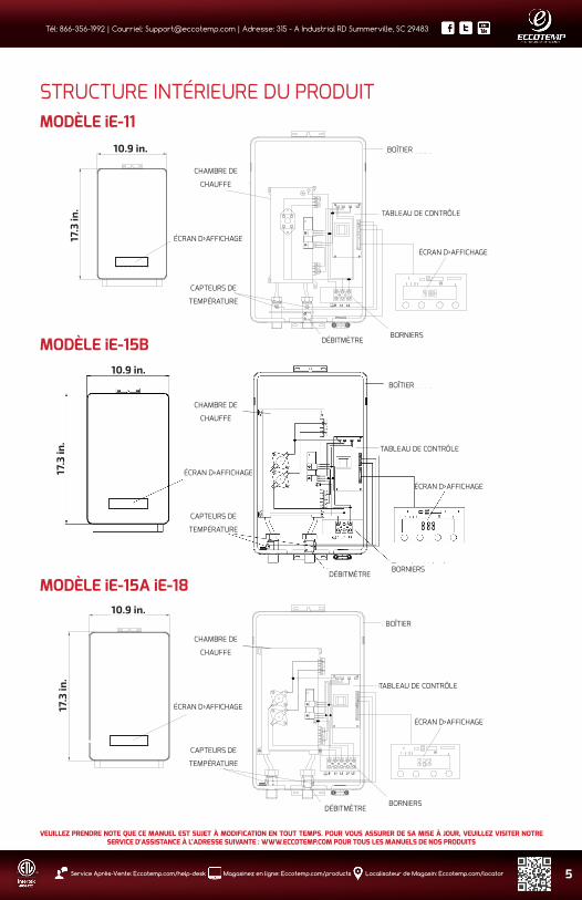
MODÈLE iE-11
MODÈLE iE-15B
STRUCTURE INTÉRIEURE DU PRODUIT
Display screen
heating chamber
Temp.sensor
bottom case
control board
Display screen
Terminal blocksflowmeter
10.9 in.
17.3
in.
10.9 in.
17.3
in.
Display screen
heating chamber
Temp.sensor
bottom case
control board
Display screen
Terminal blocksflowmeter
10.9 in.
17.3
in.
MODÈLE iE-15A iE-18
CHAMBRE DE
CHAUFFE
BOÎTIER
TABLEAU DE CONTRÔLE
ÉCRAN D›AFFICHAGE
BORNIERSDÉBITMÈTRE
ÉCRAN D›AFFICHAGE
CAPTEURS DE
TEMPÉRATURE
CHAMBRE DE
CHAUFFE
BOÎTIER
TABLEAU DE CONTRÔLE
ÉCRAN D›AFFICHAGE
BORNIERSDÉBITMÈTRE
ÉCRAN D›AFFICHAGE
CAPTEURS DE
TEMPÉRATURE
CHAMBRE DE
CHAUFFE
BOÎTIER
TABLEAU DE CONTRÔLE
ÉCRAN D›AFFICHAGE
BORNIERSDÉBITMÈTRE
ÉCRAN D›AFFICHAGE
CAPTEURS DE
TEMPÉRATURE

Tél: 866-356-1992 | Courriel: [email protected] | Adresse: 315 - A Industrial RD Summerville, SC 29483
6 Service Après-Vente: Eccotemp.com/help-desk Magasinez en ligne: Eccotemp.com/products Localisateur de Magasin: Eccotemp.com/locator
VEUILLEZ PRENDRE NOTE QUE CE MANUEL EST SUJET À MODIFICATION EN TOUT TEMPS. POUR VOUS ASSURER DE SA MISE À JOUR, VEUILLEZ VISITER NOTRE SERVICE D’ASSISTANCE À L’ADRESSE SUIVANTE : WWW.ECCOTEMP.COM POUR TOUS LES MANUELS DE NOS PRODUITS
NOTICE D’INSTALLATIONNOTE: L’installation doit être en conformité avec le Code Électrique National, votre codes locaux concernant l’électricité et la plomberie.
1. NE PAS installer le chauffe-eau à proximité de bois d’allumage, de substances volatiles ou inflammables, ou près d’une source magnétique importante. L’unité doit uniquement être montée en position VERTICALE à proximité des raccords d’eau.
2. Ne pas installer l’unité dans une pièce qui pourrait être exposée au gel.
3. Monter l’unité sur une section plate du mur bien éloignée d’éclaboussure ou pulvérisation d’eau potentielle. Assurez-vous d’utiliser des fixations murales ou visser directement sur des montants.
4. Positionner l’unité à la verticale avec tous les raccordements de plomberie en bas de l’unité.
STRUCTURE INTÉRIEURE DU PRODUIT...
MODÈLE iE-21 iE-24 iE-27
Display screen
Temp.sensor
bottom case
control board
Display screen
flowmeter
heating chamber
Terminal blocks
10.9 in.
17.3
in.
CHAMBRE DE
CHAUFFE
BOÎTIER
TABLEAU DE CONTRÔLE
ÉCRAN D›AFFICHAGE
BORNIERSDÉBITMÈTRE
ÉCRAN D›AFFICHAGE
CAPTEURS DE
TEMPÉRATURE
1. Assurez-vous que l›appareil est intact, et que tous les raccords sont complets.
2. Veuillez vous assurer que l›alimentation principale, la pression de l›eau, les conditions de mise à terre, l›ampèremètre et le câblage rencontrent toutes les normes d›installation requises.
3. Le chauffe-eau doit être connecté à un circuit de dérivation spécialisé correctement relié à la terre avec la tension nominale correcte. La terre doit être connectée à une «barre de masse» sur le panneau à disjoncteurs.
4. Le chauffe-eau DOIT être connecté à des disjoncteurs spécialisés fixes de manière permanente. Si l›appareil de chauffage ne se trouve pas utilisé, éteindre les disjoncteurs.
5. Au moment d›installer une nouvelle unité, veuillez connecter les raccordements d›eau et mettre l›eau en route de manière à ce que l›eau coule dans l›unité avant d›allumer le courant.

VEUILLEZ PRENDRE NOTE QUE CE MANUEL EST SUJET À MODIFICATION EN TOUT TEMPS. POUR VOUS ASSURER DE SA MISE À JOUR, VEUILLEZ VISITER NOTRE SERVICE D’ASSISTANCE À L’ADRESSE SUIVANTE : WWW.ECCOTEMP.COM POUR TOUS LES MANUELS DE NOS PRODUITS
7
Tél: 866-356-1992 | Courriel: [email protected] | Adresse: 315 - A Industrial RD Summerville, SC 29483
Service Après-Vente: Eccotemp.com/help-desk Magasinez en ligne: Eccotemp.com/products Localisateur de Magasin: Eccotemp.com/locator
STRUCTURE INTÉRIEURE DU PRODUIT... EMPLACEMENT D’INSTALLATION ET MÉTHODEInstallation fixe sur le murDéterminez un emplacement approprié sur la section du mur qui rencontre toutes les conditions d’installation et de sécurité nécessaires.
Fig 2 Enlever la vis qui attachait le support à l’arrière de l’appareil.
Fig 3
1.2 in.
17.8
in.
2.5 in.
1.2 in.2.5 in.
Tenir le crochet de suspension du support arrière en position contre le mur à l’emplacement de suspension désiré. Vérifier que l’attache est à niveau. Marquez le mur là où les trous de montage devront se situer. Percez des trous de diamètre ¼” aux endroits marqués. Si vous êtes sur un montant, vissez l’attache directement sur le mur. Si vous n’êtes pas sur un montant, insérez la cheville en plastique dans le trou, et sécurisez l’attache en utilisant les vis fournies.
Fig 1 Avant et arrière de l’appareil

Tél: 866-356-1992 | Courriel: [email protected] | Adresse: 315 - A Industrial RD Summerville, SC 29483
8 Service Après-Vente: Eccotemp.com/help-desk Magasinez en ligne: Eccotemp.com/products Localisateur de Magasin: Eccotemp.com/locator
VEUILLEZ PRENDRE NOTE QUE CE MANUEL EST SUJET À MODIFICATION EN TOUT TEMPS. POUR VOUS ASSURER DE SA MISE À JOUR, VEUILLEZ VISITER NOTRE SERVICE D’ASSISTANCE À L’ADRESSE SUIVANTE : WWW.ECCOTEMP.COM POUR TOUS LES MANUELS DE NOS PRODUITS
SUITE DE L’EMPLACEMENT ET MÉTHODE D’INSTALLATION...
Fig 4 Retirez les (4) vis et les rondelles de l’unité pour libérer le capot avant. Avec précaution, soulevez le capot avant de l’unité de quelques pouces. Dégager le câble ruban en raccordant le panneau LCD avant du capot avant au tableau de contrôle principal de l’unité. Retirez le capot complètement.
Nota : Si le câble de raccordement LCD ne peut pas être dégagé, placez simplement le capot avant sur le côté et laissez le câble connecté.
Fig 5 Attachez l’unité au support de montage en faisant glisser dans les pattes. Assurez-vous que l’unité est correctement sécurisée aux deux pattes du support. Installez le bas, centrez la vis de manière à fixer l’unité au support pour terminer le montage.

VEUILLEZ PRENDRE NOTE QUE CE MANUEL EST SUJET À MODIFICATION EN TOUT TEMPS. POUR VOUS ASSURER DE SA MISE À JOUR, VEUILLEZ VISITER NOTRE SERVICE D’ASSISTANCE À L’ADRESSE SUIVANTE : WWW.ECCOTEMP.COM POUR TOUS LES MANUELS DE NOS PRODUITS
9
Tél: 866-356-1992 | Courriel: [email protected] | Adresse: 315 - A Industrial RD Summerville, SC 29483
Service Après-Vente: Eccotemp.com/help-desk Magasinez en ligne: Eccotemp.com/products Localisateur de Magasin: Eccotemp.com/locator
SUITE DE L’EMPLACEMENT ET MÉTHODE D’INSTALLATION...
Fig 6 Raccordez le câble aux borniers, veuillez noter le symbole de guidage en-dessous des borniers. iE 11, iE15B seront raccordés à un disjoncteur. iE15A, iE18 seront raccordés à deux disjoncteurs, iE21, iE24, iE27 seront raccordés à trois disjoncteurs.
Fig 7 Rattachez le câble ruban au panneau LCD si débranché et réinstallez le capot avant en utilisant les vis et les rondelles que vous aviez retirées auparavant.
Tél: 866-356-1992 | Courriel: [email protected] | Adresse: 315 - A Industrial RD Summerville, SC 29483
10 Service Après-Vente: Eccotemp.com/help-desk Magasinez en ligne: Eccotemp.com/products Localisateur de Magasin: Eccotemp.com/locator
VEUILLEZ PRENDRE NOTE QUE CE MANUEL EST SUJET À MODIFICATION EN TOUT TEMPS. POUR VOUS ASSURER DE SA MISE À JOUR, VEUILLEZ VISITER NOTRE SERVICE D’ASSISTANCE À L’ADRESSE SUIVANTE : WWW.ECCOTEMP.COM POUR TOUS LES MANUELS DE NOS PRODUITS
SUITE DE L’EMPLACEMENT ET MÉTHODE D’INSTALLATION...
Fig 8
Fig 9 Raccordez le couvercle de la soupape
Raccordez le tuyau d’eau aux raccordements d’entrée et de sortie d’eau, n’oubliez pas d’installer le joint d’étanchéité en caoutchouc.Veuillez noter : Utilisez une contre-clé quand vous installez des raccords d’eau.

VEUILLEZ PRENDRE NOTE QUE CE MANUEL EST SUJET À MODIFICATION EN TOUT TEMPS. POUR VOUS ASSURER DE SA MISE À JOUR, VEUILLEZ VISITER NOTRE SERVICE D’ASSISTANCE À L’ADRESSE SUIVANTE : WWW.ECCOTEMP.COM POUR TOUS LES MANUELS DE NOS PRODUITS
11
Tél: 866-356-1992 | Courriel: [email protected] | Adresse: 315 - A Industrial RD Summerville, SC 29483
Service Après-Vente: Eccotemp.com/help-desk Magasinez en ligne: Eccotemp.com/products Localisateur de Magasin: Eccotemp.com/locator
Raccordements d’eau1. Toute conduite d’eau doit être en conformité avec les codes de canalisation d’eau nationaux, provinciaux et locaux
applicables.2. L’unité doit être raccordée directement à l’approvisionnement en eau central. Rincez le tuyau avec de l’eau de façon à
le débarrasser de tout débris ou particule instable.3. Il est nécessaire d’utiliser des raccords d’eau ½” NPT avec les modèles iE11, utilisez des raccords d’eau ¾ “ NPT avec
les modèles suivants iE15A, iE15B, iE18, iE21, iE24, iE27.4. N’oubliez pas d’installer des joints d’étanchéité en caoutchouc aux raccords. Une fois que tous les raccordements sont
terminés, vérifiez s’il y a des fuites et faites le nécessaire pour corriger la fuite si besoin, avant de continuer.5. Raccordez l’approvisionnement en eau froide au tube fileté qui est étiqueté : “ inlet “(entrée) et l’eau chaude au tuyau
fileté étiqueté : “ outlet “ (sortie). IMPORTANT : UNE RONDELLE EN CAOUTCHOUC DOIT ÊTRE UTILISÉE POUR UNE ÉTANCHÉITÉ EFFICIENTE.
Raccordement Électrique1. Tout travail électrique doit être en conformité avec les codes électriques nationaux, provinciaux et locaux
applicables.2. Toutes les unités doivent être raccordées à un circuit spécialisé de dérivation relié à la terre de tension nominale
appropriée.3. Avant de commencer tout travail sur l’installation électrique, assurez-vous que le panneau des disjoncteurs principal
est mis hors tension(OFF) pour éviter tout danger de choc électrique, tous les montages et la plomberie doivent être terminés avant de procéder au branchement électrique.
4. iE11, iE15B peuvent être raccordés à un circuit unique, utilisez un câble d’alimentation protégé par un disjoncteur bipolaire. Raccordez l’alimentation d’eau froide au tube fileté étiqueté : “ inlet “(entrée) et l’eau chaude au tube fileté : “outlet” (sortie). IMPORTANT : UNE RONDELLE EN CAOUTCHOUC DOIT ÊTRE UTILISÉE POUR UNE ÉTANCHÉITÉ EFFICIENTE.
5. iE15A, iE 18 nécessitent deux circuits indépendants. Utilisez deux câbles d’alimentation protégés par deux disjoncteurs bipolaires séparés.
6. iE21, iE24, iE27 nécessitent trois circuits indépendants. Utiliser trois câbles d’alimentation protégés par trois disjoncteurs bipolaires séparés.
7. Au moment du branchement de l’alimentation aux borniers, veuillez vous assurer que les extrémités des câbles de métal et les borniers se touchent complètement. Ensuite, resserrer les vis pour vous assurer que le contact est entier et que le courant peut passer.
INSTRUCTIONS D’OPÉRATION1. Mettre en marche le disjoncteur pour amener l’électricité à l’unité. 2. Ouvrir le robinet d’eau pendant quelques minutes jusqu’à ce que l’eau coule de manière continue et que tout l’air soit
évacué des tuyaux d’eau. L’unité doit opérer après que les disjoncteurs aient été allumés.3. Après que l’unité ait été alimentée énergétiquement, un son peut être entendu et des lumières LED fonctionner
durant deux secondes, pas d’autre effet. L’appareil reste en mode de veille.4. Toucher le bouton marche pour mettre l’appareil en ON/OFF (MARCHE/ARRÊT). Quand l’unité est sur ON, les
lumières LED affichent la température effective de l’eau à la sortie. Quand l’appareil n’est pas en fonctionnement, l’écran passera au mode d’économie d’énergie après 15 secondes. La lumière de l’écran d’affichage sera éteinte. Touchez l’écran, il se remettra en mode opératoire.
4. Touchez et pour ajuster la température à la sortie. L’éventail des réglages de la température est de 86-127⁰ F. * Si l’unité a été mise à l’arrêt durant un moment, vous pouvez dans un premier temps recevoir un jet d’eau très chaude au moment où vous remettez l’appareil en marche. Veuillez laisser couler l’eau durant quelques secondes pour laisser la température se stabiliser. Veuillez vérifier l’eau chaude avec votre main avant de prendre une douche. * Si l’unité n’est pas utilisée pendant l’hiver, vidangez l’eau entièrement de manière à ce que le radiateur ne GÈLE pas. * Veuillez nettoyer périodiquement le filtre d’eau et la douche pour maintenir un débit d’eau libre. 5. Pesez sur la touche et maintenir appuyé durant 5 secondes pour verrouiller les touches de fonction et le
allumera l’écran d’affichage. Toutes les touches de fonction sont bloquées. Pesez sur la touche et maintenir appuyé durant 5 secondes pour lever le verrouillage de la température et le disparaîtra de l’écran d’affichage. Les touches de fonction peuvent fonctionner à présent.6. Le débit d’eau (GPM) en temps réel est affiché sur l’écran quand il y a un débit d’eau qui passe par l’appareil de
chauffage.7. Il y a une fonction de mémoire automatique pour éviter une opération répétitive, quand vous mettez en marche
l’appareil, la température qui est réglée par défaut est la même que celle qui avait été réglée la fois précédente.
SUITE DE L’EMPLACEMENT ET MÉTHODE D’INSTALLATION...

Tél: 866-356-1992 | Courriel: [email protected] | Adresse: 315 - A Industrial RD Summerville, SC 29483
12 Service Après-Vente: Eccotemp.com/help-desk Magasinez en ligne: Eccotemp.com/products Localisateur de Magasin: Eccotemp.com/locator
VEUILLEZ PRENDRE NOTE QUE CE MANUEL EST SUJET À MODIFICATION EN TOUT TEMPS. POUR VOUS ASSURER DE SA MISE À JOUR, VEUILLEZ VISITER NOTRE SERVICE D’ASSISTANCE À L’ADRESSE SUIVANTE : WWW.ECCOTEMP.COM POUR TOUS LES MANUELS DE NOS PRODUITS
DÉPANNAGEProblèmes Causes Possibles Actions Correctrices
1. Fuites sur les raccords d’entrée et de sortie A. Les raccords ne sont pas assez serrésB. Le joint en caoutchouc est usé
A. Resserrer les raccordsB. Changer le joint en caoutchouc.
2. Pas de signal LED A. L’alimentation n’est pas branchée.B. La lumière/ampoule LED est abîmée.
A. Brancher l’alimentation à l’unité.B. Changer l’ampoule LED.
3. Les touches de fonction ne fonctionnent pas
A. Pas d’eau de la douche. B. Pression de l’eau trop faible.C. Touche ou PCB abîmée.
A. Ouvrir la vanne d’eau pour obtenir de l’eau. B. Ouvrir la vanne pour obtenir de la pression.C. Changer la touche ou PCB.
4. L’eau est trop chaude A. Réglage de la température trop forte.B. Débit d’eau trop faible.
A. Régler une température moins forte.B. Ouvrir plus grand la vanne d’eau.
5. L’eau est trop froide A. Réglage de la température trop faible.B. Débit d’eau trop fort.
A. Régler une température plus forte.B. Réduire le débit d’eau.
6. Pression d’eau réduite à la sortie Filtre d’entrée ou douche bouché/obstrué. Nettoyer le filtre et la douche.
7. L’écran LED affiche E1 Température à la sortie est supérieure à 67⁰C/153⁰F.
A. Réduire la températureB. Augmenter le débit d’eau
8. L’écran LED affiche E3 Panne du capteur de température. Veuillez contacter votre distributeur local.
9. Surcharge affichée Le débit d’entrée d’eau est trop fort. Réduire le débit d’entrée d’eau
7 et 8 doivent uniquement être réalisés par des électriciens qualifiés. La personne qui a initialement installé l’unité est la personne à contacter la plus recommandée pour de l’aide.
VUE D’ENSEMBLE DESPIÈCES DE L’APPAREIL
MAINTENANCE USUELLENote : N’essayez pas de réparer le chauffe-eau par vous-même. Appelez une personne de service pour de l’assistance. Éteignez toujours l’alimentation de l’unité. Éteignez tous les disjoncteurs qui fournissent de l’énergie à l’appareil * veuillez prendre note que certaines unités sont raccordées à de multiples disjoncteurs. Éteignez TOUTE L’ALIMENTATION EN EAU et TOUTES LES ALIMENTATIONS EN ÉLECTRICITÉ.Cette unité ne nécessite pas une maintenance régulière. Néanmoins, pour assurer un débit d’eau régulier, il est recommandé de suivre les procédures suivantes.1. Retirez périodiquement les dépôts de tartre et la saleté qui peuvent s’accumuler au niveau de l’aérateur du robinet ou du pommeau de la douche.2. Il y a un écran de filtrage à l’intérieur du raccordement de sortie qui devra être nettoyé de temps en temps. Veuillez s’il vous plaît fermer le débit d’eau avant de procéder.
Écran d›Affichage
Panneau d›Affichage
Boîtier du Panneau d›Affichage
Capteur de Température
Soupape de décompression
Raccord de Sortie de l›Eau
Raccord de l›Entrée de l›Eau
Couvercle de vanne
Rondelles en caoutchouc
Couvercles étanches
Serres-câble
Capot avant
Interrupteur thermique
Ailettes Rayonnement
Chambre de Chauffe
Débitmètre
Capot arrière
Tableau d›Alimentation Principal
Bornier
Plaque isolante
VEUILLEZ PRENDRE NOTE QUE CE MANUEL EST SUJET À MODIFICATION EN TOUT TEMPS. POUR VOUS ASSURER DE SA MISE À JOUR, VEUILLEZ VISITER NOTRE SERVICE D’ASSISTANCE À L’ADRESSE SUIVANTE : WWW.ECCOTEMP.COM POUR TOUS LES MANUELS DE NOS PRODUITS
13
Tél: 866-356-1992 | Courriel: [email protected] | Adresse: 315 - A Industrial RD Summerville, SC 29483
Service Après-Vente: Eccotemp.com/help-desk Magasinez en ligne: Eccotemp.com/products Localisateur de Magasin: Eccotemp.com/locator
Eccotemp Systems, LLCInformation de Garantie LimitéeMODÈLES: iE-11 iE-15B iE-15A iE-18 iE-24 iE-27
Par la présente Eccotemp garantit que ce produit est exempt de défauts matériels en termes de matériaux et de fabrication quand installé et utilisé selon les instructions d’installation et de fonctionnement d’Eccotemp. Cette Garantie Limitée est étendue à l’acheteur original et également aux propriétaires subséquents, mais uniquement si le produit reste sur son site d’installation d’origine. Cette Garantie Limitée cesse si l’appareil est déplacé ou réinstallé à un nouvel emplacement. Il n’y a pas de garanties, explicitement ou implicitement faites ou données, autres que celles contenues dans cette Garantie Limitée. Aucun agent, employé, ou représentant d’Eccotemp n’a le pouvoir de lier Eccotemp à une représentation ou une garantie concernant le Produit qui n’est pas contenue dans cette Garantie Limitée. Eccotemp se réserve le droit et l’autorité de changer, de modifier, ou d’altérer cette garantie en tout temps.
À l’exception des clauses expressément stipulées dans les présentes: IL N’Y A PAS DE REPRÉSENTATIONS OU DE GARANTIES, EXPLICITES OU IMPLICITES, INCLUANT, SANS LIMITATION, QUANT À UNE VALEUR MARCHANDE OU CONFORMITÉ POUR UN USAGE PARTICULIER EN RELATION À TOUTE MARCHANDISE VENDUE CI-APRÈS. L’UNIQUE RECOURS DE L’ACHETEUR EST LIMITÉ À LA RÉPARATION OU LE REMPLACEMENT DES BIENS VENDUS, À LA DISCRÉTION D’ECCOTEMP. ECCOTEMP NE SERA PAS TENU RESPONSABLE POUR DES DOMMAGES ACCESSOIRES OU CONSÉCUTIFS.
Période de Garantie Limitée
Cette Garantie est étendue par Eccotemp Systems à l’Acheteur. Cette garantie prend effet à partir de la date de l’installation du produit ou 30 jours après la date d’achat, relativement à ce qui se produira en premier lieu, et est effective jusqu’à l’anniversaire spécifié de la date à laquelle on se réfère comme suit:
Période de Couverture de l’Item
Élément/Chambre de Chauffe 3 ansTous les autres parties 2 ans
La couverture est annulée si l’unité est utilisée en boucle de circulation d’eau chaude, dans les séries avec un système de circulation ou quand un système en recirculation à la demande n’est pas incorporé.
Le propriétaire est responsable pour tous les coûts accessoires de réparation tels que main d’œuvre, envoi, livraison et autorisations. Une preuve de paiement est requise. Les produits réparés seront couverts dans les limites de la Garantie Limitée pour le terme restant relativement à l’achat d’origine.
Exclusions
Veuillez vous référer au Manuel d’Installation et au Manuel d’Utilisation et d’Entretien fournis avec votre produit Eccotemp Systems. Cette Garantie Limitée devient nulle et non avenue si une des causes mentionnées ci-après est déterminée par Eccotemp comme ayant été un facteur déterminant dans la panne du produit:
1. Abus, mauvais usage, altération, négligence ou application erronée.2. Procédures d’entretien incorrectes, dangereuses, destructrices ou entretien inadéquat.3. Dommages causés par des services réalisés par des réparateurs autres qu’Eccotemp Systems.4. Installation dans un environnement corrosif ou autrement destructeur.5. Dommages résultant du gel à l’intérieur de l’unité ou dans les tuyaux avoisinants.6. Production de dépôts de tartre.7. Tension, ampères ou pression incorrects.8. Actes de force majeure.9. Dommages résultant de l’utilisation avec de l’eau non-transportable, non-traitée ou incorrectement traitée, ou de l’eau avec
des PH élevés ou des niveaux de dureté supérieurs à 12 grains par gallon (200mg/L).10. Calibrage incorrect pour l’application.11. Produits dont les numéros de série d’origine ont été enlevés ou altérés et qui ne peuvent pas être clairement déterminés.12. Évènements de force majeure incluant mais non limités au feu, à l’inondation ou à un désastre naturel.

Tél: 866-356-1992 | Courriel: [email protected] | Adresse: 315 - A Industrial RD Summerville, SC 29483
14 Service Après-Vente: Eccotemp.com/help-desk Magasinez en ligne: Eccotemp.com/products Localisateur de Magasin: Eccotemp.com/locator
VEUILLEZ PRENDRE NOTE QUE CE MANUEL EST SUJET À MODIFICATION EN TOUT TEMPS. POUR VOUS ASSURER DE SA MISE À JOUR, VEUILLEZ VISITER NOTRE SERVICE D’ASSISTANCE À L’ADRESSE SUIVANTE : WWW.ECCOTEMP.COM POUR TOUS LES MANUELS DE NOS PRODUITS
Ce produit ne doit pas être utilisé comme un appareil de chauffage de piscine ou de spa.
Dans l’éventualité où Eccotemp Systems reconnaîtrait un défaut, un dysfonctionnement ou une panne conforme à cette Garantie et se fondant sur l’approbation d’Eccotemp d’une réclamation sous garantie, Eccotemp Systems, à sa seule et absolue discrétion, règlera la réclamation sous garantie du défaut, dysfonctionnement ou panne pour se conformer à cette Garantie. Afin de pouvoir faire une réclamation sous cette Garantie, Le Propriétaire doit notifier Eccotemp de la panne du Produit pour se conformer à cette Garantie.
Dans les termes de cette Garantie, Eccotemp Systems fournira uniquement des pièces de rechange tel que décrit dans la “Période de Garantie Limitée”. Le Propriétaire sera responsable pour tout coût causé, ce qui inclut les frais de main-d’œuvre pour l’entretien de l’unité, l’envoi, la livraison et la manutention de la pièces de rechange, le coût pour les autorisations ou le matériel nécessaire pour la réparation, ou tout coût accessoire résultant du dommage extérieur à l’unité résultant de la panne.
NONOBSTANT DANS CETTE GARANTIE TOUTES DISPOSITIONS CONTRAIRES, EXCEPTION FAITE DANS LES OBLIGATIONS AFFIRMATIVES DE ECCOTEMP SYSTEMS EXPRESSÉMENT MISES EN PLACE DANS CETTE GARANTIE, ECCOTEMP SYSTEMS DÉCLINE TOUTES GARANTIES, QU’ELLES SOIENT EXPLICITES OU IMPLICITES, RELATIVES AU PRODUIT ET À SA FONCTIONNALITÉ, PERFORMANCE, VALEUR COMMERCIALE, D’ADAPTATION POUR UN USAGE PARTICULIER OU DES DROITS DE PROPRIÉTÉ INTELLECTUELLE. ECCOTEMP SYSTEMS DÉCLINE TOUTES AUTRES OBLIGATIONS OU RESPONSABILITÉS DE SON CÔTÉ ET NE PERMET NI N’AUTORISE QUICONQUE D’ASSUMER POUR ECCOTEMP SYSTEMS ET AUTRES RESPONSABILITÉS EN RELATION AVEC LA PERFORMANCE DU PRODUIT. CETTE GARANTIE COUVRE UNIQUEMENT LES PIÈCES DE RECHANGE ET NE COUVRE PAS LE COÛT DE LA MAIN-D’OEUVRE OU DES SERVICES EN AUCUNE CIRCONSTANCE.
Systems pour toute autre partie pour des dommages de quelque sorte que ce soit, mais non limités à des dommages accessoires et consécutifs, qui résultent de l’objet du présent Accord. Certains États n’acceptent pas l’exclusion ou les limitations des dommages accessoires ou consécutifs, ainsi la limitation ci-dessus ou l’exclusion pourrait ne pas s’appliquer à votre cas. Cette garantie vous donne des droits légaux spécifiques. Vous pourriez également avoir d’autres droits qui peuvent varier d’un État à un Autre.
JETEZ UN COUP D’OEIL À CERTAINS DE NOS AUTRES PRODUITS ECCOTEMP
COMPARAISONS DE PRODUITS POUR LA MAISON

VEUILLEZ PRENDRE NOTE QUE CE MANUEL EST SUJET À MODIFICATION EN TOUT TEMPS. POUR VOUS ASSURER DE SA MISE À JOUR, VEUILLEZ VISITER NOTRE SERVICE D’ASSISTANCE À L’ADRESSE SUIVANTE : WWW.ECCOTEMP.COM POUR TOUS LES MANUELS DE NOS PRODUITS
15
Tél: 866-356-1992 | Courriel: [email protected] | Adresse: 315 - A Industrial RD Summerville, SC 29483
Service Après-Vente: Eccotemp.com/help-desk Magasinez en ligne: Eccotemp.com/products Localisateur de Magasin: Eccotemp.com/locator
BTU
Débit
Portable
Source d’Alimentation
Type de Gaz
Ventilation
Pression de l’Eau
Régulateur et Tuyau
Contrôle de la Température
Garantie
Dimensions du Produit
Dimensions de l’Emballage
INSTALLATION
i12fvi12
À L’INTÉRIEUR UNIQUEMENT
74,000
3.6 GPM
No
120 VAC
Disponible en gas natural y LP
2.5 “de ventilación horizontal (Incl)
20-80 PSI
No incluido
Manual 80° - 120°
2 años limitada
15” x 4” x 24” - 30 lbs
17” x 11” x 28” - 32 lbs
JETEZ UN COUP D’OEIL À CERTAINS DE NOS AUTRES PRODUITS ECCOTEMP
COMPARAISONS DE PRODUITS POUR LA MAISON
fvi12
À L’INTÉRIEUR UNIQUEMENT
80,000
3 GPM
No
120 VAC
Disponible en NG & LP
2.5” Ventilation horizontale (incl)
20-80 PSI – Débit activé
Non Inclus
Automatique 80°-120°
Limitée à 2 ans
14”x5”x24” – 30 lbs
17”x11”x29” – 32 lbs
i12
À L’EXTÉRIEUR UNIQUEMENT
140,000
6.8 GPM
No
120 VAC
Disponible en NG & LP
Non Nécessaire
20-80 PSI – Débit activé
Non Inclus
Automatique 90°-140°
10 Ans – Échangeur thermique5 Ans - Pièces
15”x5”x24” – 38 lbs
16”x7.5”x26” – 40 lbs
45-H
À L’INTÉRIEUR UNIQUEMENT
140,000
6.8 GPM
No
120 VAC
Disponible en NG & LP
Vendue Séparément
20-80 PSI – Débit activé
Non Inclus
Automatique 90°-140°
10 Ans – Échangeur thermique5 Ans - Pièces
15”x5”x24” – 38 lbs
16”x7.5”x26” – 40 lbs
45-HI
45-H 45-HI

Tél: 866-356-1992 | Courriel: [email protected] | Adresse: 315 - A Industrial RD Summerville, SC 29483
Service Après-Vente: Eccotemp.com/help-desk Magasinez en ligne: Eccotemp.com/products Localisateur de Magasin: Eccotemp.com/locator
VEUILLEZ PRENDRE NOTE QUE CE MANUEL EST SUJET À MODIFICATION EN TOUT TEMPS. POUR VOUS ASSURER DE SA MISE À JOUR, VEUILLEZ VISITER NOTRE SERVICE D’ASSISTANCE À L’ADRESSE SUIVANTE : WWW.ECCOTEMP.COM POUR TOUS LES MANUELS DE NOS PRODUITS


Phone: 866-356-1992 | Email: [email protected] | Address: 315 - A Industrial RD Summerville, SC 29483
Product Support: Eccotemp.com/help-desk Shop Online: Eccotemp.com/products Store Locater: Eccotemp.com/locater
PLEASE NOTE: THIS MANUAL IS SUBJECT TO CHANGE AT ANYTIME, TO ENSURE THIS MANUAL IS UP TO DATE PLEASE VISIT OUR HELP DESKAT WWW.ECCOTEMP.COM FOR ALL OF OUR PRODUCT MANUALS.
Eccotemp Systems, LLC315-A Industrial Road
Summerville, SC 29483866-356-1992
RIESGO DEDESCARGA ELÉCTRICA
CLASIFICACIÓN:
VELOCIDAD DEFLUJO:
CALENTADOR DE AGUA ELÉCTRICO SIN TANQUE
4002422
MODELO #:
iE-11240Vac, 60Hz, 11000W
0.85-3.2 GPM
CLASIFICACIÓN REQUERIDA DEL CORTACIRCUITOS:60A
DE ACUERDO A UL STD. 499CERTIFICADO POR CSA STD. C22.2 NO.64-10
NÚMERO SERIAL:
HECHO EN CHINA
PRECAUCIÓN Y AVERTENCIA:
SÓLO PARA USO INTERIOR Y DOMÉSTICO POUR LES MENAGES
ETL’ UTILISTATION A L’INTERIEURSEULEMENT.
Eccotemp Systems, LLC315-A Industrial Road
Summerville, SC 29483866-356-1992
CLASIFICACIÓN:
VELOCIDAD DEFLUJO:
RIESGO DEDESCARGA ELÉCTRICA
CALENTADOR DE AGUA ELÉCTRICO SIN TANQUE
4002422
MODELO #:
iE-15B240Vac, 60Hz, 15000W
0.85-3.2 GPM
CLASIFICACIÓN REQUERIDA DEL CORTACIRCUITOS:80A
DE ACUERDO A UL STD. 499CERTIFICADO POR CSA STD. C22.2 NO.64-10
NÚMERO SERIAL:
HECHO EN CHINA
PRECAUCIÓN Y AVERTENCIA:
SÓLO PARA USO INTERIOR Y DOMÉSTICO POUR LES MENAGES
ETL’ UTILISTATION A L’INTERIEURSEULEMENT.
Eccotemp Systems, LLC315-A Industrial Road
Summerville, SC 29483866-356-1992
CALENTADOR DE AGUA ELÉCTRICO SIN TANQUE
4002422
MODELO #:
iE-15ACLASIFICACIÓN: 240Vac, 60Hz, 15000W
VELOCIDAD DEFLUJO: 0.85-3.2 GPM
CLASIFICACIÓN REQUERIDA DEL CORTACIRCUITOS:2x40A
DE ACUERDO A UL STD. 499CERTIFICADO POR CSA STD. C22.2 NO.64-10
NÚMERO SERIAL:
HECHO EN CHINA
PRECAUCIÓN Y AVERTENCIA:
SÓLO PARA USO INTERIOR Y DOMÉSTICO POUR LES MENAGES
ETL’ UTILISTATION A L’INTERIEURSEULEMENT.
RIESGO DEDESCARGA ELÉCTRICA
Eccotemp Systems, LLC315-A Industrial Road
Summerville, SC 29483866-356-1992
RIESGO DEDESCARGA ELÉCTRICA
CALENTADOR DE AGUA ELÉCTRICO SIN TANQUE
4002422
MODELO #:
iE-18240Vac, 60Hz, 18000W
0.85-4.2 GPM
CLASIFICACIÓN REQUERIDA DEL CORTACIRCUITOS:2x50A
DE ACUERDO A UL STD. 499CERTIFICADO POR CSA STD. C22.2 NO.64-10
NÚMERO SERIAL:
HECHO EN CHINA
PRECAUCIÓN Y AVERTENCIA:
SÓLO PARA USO INTERIOR Y DOMÉSTICO POUR LES MENAGES
ETL’ UTILISTATION A L’INTERIEURSEULEMENT.
CLASIFICACIÓN:
VELOCIDAD DEFLUJO:
Eccotemp Systems, LLC315-A Industrial Road
Summerville, SC 29483866-356-1992
RIESGO DEDESCARGA ELÉCTRICA
CLASIFICACIÓN:
VELOCIDAD DEFLUJO:
CALENTADOR DE AGUA ELÉCTRICO SIN TANQUE
4002422
MODELO #:
iE-24240Vac, 60Hz, 24000W
0.85-6 GPM
CLASIFICACIÓN REQUERIDA DEL CORTACIRCUITOS:3x40A
DE ACUERDO A UL STD. 499CERTIFICADO POR CSA STD. C22.2 NO.64-10
NÚMERO SERIAL:
HECHO EN CHINA
PRECAUCIÓN Y AVERTENCIA:
SÓLO PARA USO INTERIOR Y DOMÉSTICO POUR LES MENAGES
ETL’ UTILISTATION A L’INTERIEURSEULEMENT.
Eccotemp Systems, LLC315-A Industrial Road
Summerville, SC 29483866-356-1992
CLASIFICACIÓN:
VELOCIDAD DEFLUJO:
RIESGO DEDESCARGA ELÉCTRICA
CALENTADOR DE AGUA ELÉCTRICO SIN TANQUECALENTADOR DE AGUA ELÉCTRICO SIN TANQUE
4002422
MODELO #:
iE-27240Vac, 60Hz, 27000W
0.85-6 GPM
CLASIFICACIÓN REQUERIDA DEL CORTACIRCUITOS:3x50A
DE ACUERDO A UL STD. 499CERTIFICADO POR CSA STD. C22.2 NO.64-10
NÚMERO SERIAL:
HECHO EN CHINA
PRECAUCIÓN Y AVERTENCIA:
SÓLO PARA USO INTERIOR Y DOMÉSTICO POUR LES MENAGES
ETL’ UTILISTATION A L’INTERIEURSEULEMENT.

Phone: 866-356-1992 | Email: [email protected] | Address: 315 - A Industrial RD Summerville, SC 29483
Product Support: Eccotemp.com/help-desk Shop Online: Eccotemp.com/products Store Locater: Eccotemp.com/locater
PLEASE NOTE: THIS MANUAL IS SUBJECT TO CHANGE AT ANYTIME, TO ENSURE THIS MANUAL IS UP TO DATE PLEASE VISIT OUR HELP DESKAT WWW.ECCOTEMP.COM FOR ALL OF OUR PRODUCT MANUALS.
ADVERTENCIA
Si su calentador de agua requiere un reinicio, asegúrese de apagar los interruptores antes de reiniciar la unidad.
Reiniciar su unidad sin apagar los interruptores puede resultar en lesiones personales y daños en su calentador de agua.
¡ADVERTENCIA! Hay agua contenida en las enroscaduras de su calentador de agua en todo momento. Si su calentador de agua es expuesto a temperaturas de congelación, el agua en las enroscaduras puede congelarse, causando una interrupción en el intercambiador calórico de la unidad, o en las líneas de suministro y retorno. Este tipo de daño causará que el agua corra libremente en el espacio donde se encuentra el calentador de agua, esto puede ocasionar inundaciones. NO instale este calentador de agua en donde pueda congelarse. Si su calentador de agua se encuentra en una zona donde la congelación es posible, debe apagar el flujo de agua al calentador y drenar cualquier remanente de agua desconectando las líneas de agua. Las líneas de agua deben permanecer desconectadas hasta el momento de la utilización del calentador de agua.
Guía de inicio rápidoiE-18 | iE-21 | iE-24 | iE-27
1) MontajeMontar verticalmente sobre una superficie plana (ejem. tablero o pared) más grande que la unidad. Asegúrese de que el soporte sea seguro mediante el uso de un poste o los anclajes de pared suministrados. Mantener alejado de cualquier salpicaduras, fugas de agua y campos magnéticos fuertes.
2) Conexiones de aguaAl instalar sus conexiones de agua asegúrese de usar acoples NPT de 3/4”. Por favor, utilice las juntas proporcionadas para evitar fugas. Al ajustar los acoples utilicen una llave de seguridad en los acoples de entrada y de salida (lados planos de los acoples se encuentran detrás de la cubierta). Se recomienda instalar una válvula de descarga de alta presión y una válvula de cierre en la línea de entrada de agua, en ese orden. Abra un grifo y deje correr el agua por la unidad durante unos pocos minutos para sacar el aire, cierre el grifo para aumentar la presión en la línea y así comprobar que no haya fugas.
3) Conexiones eléctricasEl cableado para las conexiones eléctricas será diferente dependiendo del modelo, por favor verifique el tipo de modelo en el lado derecho de la unidad.
4) FuncionamientoLa unidad se activa por el flujo de agua a través de la entrada. Un punto de ajuste de la temperatura deseada se selecciona mediante el uso de los botones “arriba” o “abajo”, si la unidad no responde presione el botón central de “energía” y vuelva a intentarlo. Pruebe el agua para prevenir quemaduras.
iE-18
E L1 L2 L1 L2
Suelo Interruptor1 Interruptor2iE-18 - Dos interruptores 22ov de 50 amp con Polos Dobles
iE-21, iE-24, iE-27
E L1 L2 L1 L2
iE-21, iE-24, iE-27 – Tres interruptores 22ov de 50 amp con Polos Dobles
L1 L2
Suelo Interruptor1 Interruptor2 Interruptor3
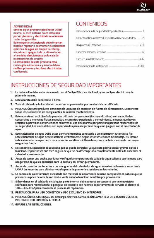
Teléfono: 866-356-1992 | Email: [email protected] | Dirección: 315 - A Industrial RD Summerville, SC 29483
POR FAVOR NOTE: ESTE MANUAL ESTÁ SUJETO A CAMBIOS EN CUALQUIER MOMENTO, PARA ASEGURAR QUE ESTE MANUAL SE ENCUENTRE ACTUALIZADO REVISE NUESTRO SITIO DE AYUDA WWW.ECCOTEMP.COM PARA TODOS LOS MANUALES DE NUESTROS PRODUCTOS
1Product Support: Eccotemp.com/help-desk Shop Online: Eccotemp.com/products Store Locater: Eccotemp.com/locater
INSTRUCCIONES DE SEGURIDAD IMPORTANTES1. La instalación debe estar de acuerdo con el Código Eléctrico Nacional, y los códigos eléctricos y de
plomería locales.
2. Este aparato debe conectarse a tierra.
3. Todo el cableado y la instalación deben ser supervisados por un electricista calificado.
4. PRECAUCIÓN: Este producto tiene más de un punto de conexión de fuente de alimentación. Desconecte todos los suministros de energía antes de realizar mantenimiento.
5. Este aparato no está diseñado para ser utilizado por personas (incluyendo niños) con capacidades sensoriales o mentales físicas reducidas, o carentes experiencia y conocimiento, a menos que hayan recibido supervisión o instrucciones relativas al uso del aparato por parte una persona responsable de su seguridad. Los niños deben ser supervisados para asegurarse de que no jueguen con el calentador de agua.
6. Este calentador de agua DEBE estar permanentemente conectado a un interruptor automático fijo. Este calentador de agua debe instalarse verticalmente, según las instrucciones de montaje. NO instale este calentador de agua cerca de sustancias volátiles o inflamables, cerca de leña o cerca de un campo magnético fuerte.
7. No conecte el calentador si sospecha que se puede congelar, ya que esto podría causar graves daños a la unidad. Espere hasta que esté seguro de que se ha descongelado completamente antes de encender el calentador nuevamente.
8. Antes de tomar una ducha, por favor verifique la temperatura de salida de agua caliente con la mano para asegurarse de que es adecuada para la ducha y así evitar quemaduras.
9. Antes de conectar las tuberías a las mangueras del calentador de agua, es extremadamente importante LAVAR las tuberías para eliminar toda la pasta de plomería o residuos en las tuberías.
10. La cámara de calentamiento es tratada con material de aislamiento de nano compuesto; es natural que se presente un poco de olor, humo azul o verde cuando la unidad se utiliza por primera vez.
11. Si hay daños en el cableado o cualquier parte interna, debe ponerse en contacto con un electricista calificado para reemplazarla, o póngase en contacto con nuestro departamento de servicio al cliente al 1-866-356-1992 para comenzar el proceso de reparación.
12. PRECAUCIÓN: PARA USO DOMÉSTICO Y USO EXCLUSIVO EN INTERIORES.
13. PRECAUCIÓN: EXISTE RIESGO DE descarga eléctrica, CONECTE ÚNICAMENTE A UN CIRCUITO QUE ESTE PROTEGIDO POR CONEXIÓN A TIERRA.
14. GUARDE LAS INSTRUCCIONES.
ADVERTENCIASEste no es un proyecto para hacer usted mismo. Si este sistema no es instalado por un plomero y electricista se anularán todas las garantías.Bajo ninguna circunstancia debe intentar instalar, reparar o desmontar el calentador eléctrico de agua sin tanque Eccotemp sin primero apagar toda la alimentación a la unidad directamente en la caja de interruptores de circuito.La instalación de este producto está restringida a interiores y sólo la deben realizar plmeros y técnicos electricistas con licencia.
CONTENIDOSInstrucciones de Seguridad Importantes -------------------- 1
Características del Producto y Usos Recomendados ------ 2
Diagramas Eléctricos --------------------------------------- 2-3
Especificaciones Técnicas ------------------------------------ 4
Estructura del Producto ------------------------------------ 4-6
Instrucciones de Instalación ------------------------------ 6-10

Teléfono: 866-356-1992 | Email: [email protected] | Dirección: 315 - A Industrial RD Summerville, SC 29483
2 Product Support: Eccotemp.com/help-desk Shop Online: Eccotemp.com/products Store Locater: Eccotemp.com/locater
POR FAVOR NOTE: ESTE MANUAL ESTÁ SUJETO A CAMBIOS EN CUALQUIER MOMENTO, PARA ASEGURAR QUE ESTE MANUAL SE ENCUENTRE ACTUALIZADO REVISE NUESTRO SITIO DE AYUDA WWW.ECCOTEMP.COM PARA TODOS LOS MANUALES DE NUESTROS PRODUCTOS
CARACTERÍSTICAS DEL PRODUCTOLos calentadores eléctricos de agua sin tanque Eccotemp iE incluyen tecnología patentada con múltiples dispositivos de seguridad, incluyendo las siguientes características:
1. Sin tanque, para calentamiento instantáneo de la demanda de agua caliente, Sin precalentamiento. No hay pérdida de calentamiento por espera. Ahorra energía.
2. Control por micro-computador, adopta nueva tecnología de calefacción patentada. El agua está completamente separada de la electricidad por varias capas de material aislante de nano material.
3. Pausa por exceso de calentamiento térmico para evitar quemaduras. Una vez que la temperatura de salida del agua llega a 153 °F/67 °C, la electricidad se corta automáticamente. Si esto ocurre, la pantalla emitirá un pitido y mostrará un código de error E1.
4. Mal funcionamiento del sensor. Si hay un mal funcionamiento del sensor de temperatura, el calentador dejará de funcionar y mostrará un código de error E3.
5. Corte térmico por calentamiento seco. En caso de calentamiento en seco, la electricidad de la unidad será cortada y se mostrará un código de error E4.
6. Ventaja del producto Eccotemp: los elementos de calefacción Eccotemp iE están hechos de una sola pieza de aluminio fundido; por lo que nunca habrá fugas de agua o fugas no eléctrica en la cámara de calentamiento.
USOS RECOMENDADOSiE-11 -Clasificación 1.8 GPM @ 40 grados de aumento de temperatura 1 a 2 aplicaciones individuales como ducha individual, lavabo, lavadora, lavavajillas situado en climas más cálidos, con un promedio de temperatura del agua de entrada por encima de 65 grados F.No recomendado para: aplicaciones múltiples, climas fríos con temperatura promedio del agua de 50 grados F o menor.
iE-15B - Clasificación at 1.8 GPM @ 40 grados de aumento de temperaturaIndividual, punto único de soporte para uso de aplicaciones como lava platos, lavadora, sólo una ducha situada en climas más cálidos con un promedio de temperatura del agua de entrada por encima de 65 grados F.No recomendado para: aplicaciones múltiples, climas fríos con temperatura promedio del agua de 50 grados F o menor.
iE-15A - Clasificación at 2 GPM @ 40 grados de aumento de temperaturaPunto único de para uso de aplicaciones como lava platos independiente, lavadora, sólo una ducha situada en climas más cálidos con un promedio de temperatura del agua de entrada por encima de 65 grados F.No recomendado para: aplicaciones múltiples, climas fríos con temperatura promedio del agua de 50 grados F o menor.
iE-18 - Clasificación at 2.5 GPM @40 grados de aumento de temperatura1 a 2 aplicaciones tales como ducha independiente, lava platos, lava manos, lavadora.No recomendado para: aplicaciones múltiples, climas fríos con temperatura promedio del agua de 50 grados F o menor; no destinado para el uso de más de dos aplicaciones al tiempo.
iE-24 - Clasificación at 3 GPM @40 grados de aumento de temperaturaCabina pequeña, apartamento, oficina o cualquier otra vivienda pequeña con 2 aplicaciones a la vez.No recomendado: instalación de todo el hogar o multi vivienda familiar; no destinadas a su uso en más de 2 aplicaciones a la vez.
iE-27 - Clasificación at 3.5 GPM @40 grados de aumento de temperaturaLugar de medio a pequeño de 3 dormitorios, 2 baños (idealmente bajo 2500 pies cuadrados); cualquier otra vivienda con 3 aplicaciones o menos.No recomendado: grandes casas o cualquier otra vivienda grande; no destinadas a su uso en más de 3 aplicaciones a la vez.

Teléfono: 866-356-1992 | Email: [email protected] | Dirección: 315 - A Industrial RD Summerville, SC 29483
POR FAVOR NOTE: ESTE MANUAL ESTÁ SUJETO A CAMBIOS EN CUALQUIER MOMENTO, PARA ASEGURAR QUE ESTE MANUAL SE ENCUENTRE ACTUALIZADO REVISE NUESTRO SITIO DE AYUDA WWW.ECCOTEMP.COM PARA TODOS LOS MANUALES DE NUESTROS PRODUCTOS
3Product Support: Eccotemp.com/help-desk Shop Online: Eccotemp.com/products Store Locater: Eccotemp.com/locater
DIAGRAMA ELÉCTRICOMODELO iE-11 iE-15B
L1T1
T2
R1
R2
L2
E
THERMAL CUT-OUT 95℃
CONTROL SYSTEM
DISPLAYSCREEN INLET TEMP.SENSOR
FLOWMETER
OUTLET TEMP.SENSOR
REMARK: J:RELAY R:HEATING SYSTEM T:TRIAC
MODELO iE-15A iE-18
L1
L1'
T1
T2
R1
R2
L2
E
THERMAL CUT-OUT 90℃
CONTROL SYSTEM
DISPLAYSCREEN INLET TEMP.SENSOR
FLOWMETER
OUTLET TEMP.SENSOR
REMARK: J:RELAY R:HEATING SYSTEM T:TRIAC
L2'
SENSORES DE TEMPERATURA DE SALIDASENSORES DE TEMPERATURA DE ENTRADA
MEDIDOR DE FLUJO
PANTALLA
SISTEMA DE
CONTROL
OBSERVACIÓN: J:RELAY R:HEATING SYSTEM T:TRIAC
LIMITACIÓN TÉRMICA 95 °C
SENSORES DE TEMPERATURA DE SALIDA SENSORES DE TEMPERATURA DE ENTRADA
MEDIDOR DE FLUJO
PANTALLA
SISTEMA DE
CONTROL
OBSERVACIÓN: J:RELAY R:HEATING SYSTEM T:TRIAC
LIMITACIÓN TÉRMICA 90 °C

Teléfono: 866-356-1992 | Email: [email protected] | Dirección: 315 - A Industrial RD Summerville, SC 29483
4 Product Support: Eccotemp.com/help-desk Shop Online: Eccotemp.com/products Store Locater: Eccotemp.com/locater
POR FAVOR NOTE: ESTE MANUAL ESTÁ SUJETO A CAMBIOS EN CUALQUIER MOMENTO, PARA ASEGURAR QUE ESTE MANUAL SE ENCUENTRE ACTUALIZADO REVISE NUESTRO SITIO DE AYUDA WWW.ECCOTEMP.COM PARA TODOS LOS MANUALES DE NUESTROS PRODUCTOS
DATOS TÉCNICOSModelo iE-11 iE-15B iE-15A iE-18 iE-21 iE-24 iE-27
Fase 1 1 1 1 1 1 1
Voltaje V 240 240 240 240 240 240 240
Vatiaje kW 11 15 15 18 21 24 27
Máxima Carga de Amplitud A 50 63 63 75 88 100 113
Amp Mín por InterruptoresA 60 80 2 X 40 2x50 3 X 40 3 X 40 3 X 50
Tamaño Mín. Cabñe AWG de Cobre 8 6 2 X 8 2 X 8 3 X 8 3 X 8 3 X 8
Mín. Flujo de Agua para Activación GPM / L/min.
0.53 / 2 0.85 / 3.2 0.85 / 3.2 0.85 / 3.2 0.85 / 3.2 0.85 / 3.2
Peso lbs. 7 11 11 11 12 12 12
Dimensiones del Producto pulgadas 17.3x10.9x3.5
Conexiones NPT de Agua 1/2” 3/4” 3/4” 3/4” 3/4” 3/4” 3/4”
Nota: * Se facilitarán los medios adecuados de alivio de tensión cuando se instale el producto.
CONTINUACIÓN DEL DIAGRAMA ELÉCTRICO...MODELO iE-21 iE-24 iE-27
L1
L1'
L1"
T1
T2
T3
R1
R2
R3L2"E
THERMAL CUT-OUT 90℃
CONTROL SYSTEM
DISPLAYSCREEN INLET TEMP.SENSOR
FLOWMETER
OUTLET TEMP.SENSOR
REMARK: J:RELAY R:HEATING SYSTEM T:TRIAC
L2
L2'
SENSORES DE TEMPERATURA DE SALIDASENSORES DE TEMPERATURA DE ENTRADA
MEDIDOR DE FLUJO
PANTALLA
SISTEMA DE
CONTROL
OBSERVACIÓN: J:RELAY R:HEATING SYSTEM T:TRIAC
LIMITACIÓN TÉRMICA 90 °C

Teléfono: 866-356-1992 | Email: [email protected] | Dirección: 315 - A Industrial RD Summerville, SC 29483
POR FAVOR NOTE: ESTE MANUAL ESTÁ SUJETO A CAMBIOS EN CUALQUIER MOMENTO, PARA ASEGURAR QUE ESTE MANUAL SE ENCUENTRE ACTUALIZADO REVISE NUESTRO SITIO DE AYUDA WWW.ECCOTEMP.COM PARA TODOS LOS MANUALES DE NUESTROS PRODUCTOS
5Product Support: Eccotemp.com/help-desk Shop Online: Eccotemp.com/products Store Locater: Eccotemp.com/locater
MODELO iE-11
MODELO iE-15B
ESTRUCTURA INTERNA DEL PRODUCTO
Display screen
heating chamber
Temp.sensor
bottom case
control board
Display screen
Terminal blocksflowmeter
10.9 in.
17.3
in.
10.9 in.
17.3
in.
Display screen
heating chamber
Temp.sensor
bottom case
control board
Display screen
Terminal blocksflowmeter
10.9 in.
17.3
in.
MODELO iE-15A iE-18
CÁMARA DE
CALENTAMIENTO
CARCASA INFERIOR
TABLERO DE CONTROL
PANTALLA
CONECTORESMEDIDOR DE FLUJO
PANTALLA
SENSOR DE
TEMPERATURA
CÁMARA DE
CALENTAMIENTO
CARCASA INFERIOR
TABLERO DE CONTROL
PANTALLA
CONECTORESMEDIDOR DE FLUJO
PANTALLA
SENSOR DE
TEMPERATURA
CÁMARA DE
CALENTAMIENTO
CARCASA INFERIOR
TABLERO DE CONTROL
PANTALLA
CONECTORESMEDIDOR DE FLUJO
PANTALLA
SENSOR DE
TEMPERATURA

Teléfono: 866-356-1992 | Email: [email protected] | Dirección: 315 - A Industrial RD Summerville, SC 29483
6 Product Support: Eccotemp.com/help-desk Shop Online: Eccotemp.com/products Store Locater: Eccotemp.com/locater
POR FAVOR NOTE: ESTE MANUAL ESTÁ SUJETO A CAMBIOS EN CUALQUIER MOMENTO, PARA ASEGURAR QUE ESTE MANUAL SE ENCUENTRE ACTUALIZADO REVISE NUESTRO SITIO DE AYUDA WWW.ECCOTEMP.COM PARA TODOS LOS MANUALES DE NUESTROS PRODUCTOS
INSTRUCCIONES DE INSTALACIÓNNOTA: La instalación debe hacerse de acuerdo con el Código Eléctrico Nacional, los códigos eléctricos y de plomería locales.
1. No instale el calentador de agua cerca de leña, sustancias volátiles o inflamables, o cerca de un campo magnético fuerte. La unidad sólo debe montarse en posición vertical cerca de las instalaciones de agua.
2. No instale la unidad en una habitación donde exista posibilidad de congelación.
3. Monte la unidad a una sección plana de la pared, lejos de cualquier posible salpicadura de agua o aerosol. Asegúrese de utilizar los anclajes de pared o atornillar directamente en los postes.
4. Coloque la unidad en posición vertical con todas las conexiones de plomería en la parte inferior de la unidad.
ONTINUACIÓN DE LA ESTRUCTURA INTERNA DEL PRODUCTO...
MODELO iE-21 iE-24 iE-27
Display screen
Temp.sensor
bottom case
control board
Display screen
flowmeter
heating chamber
Terminal blocks
10.9 in.
17.3
in.
CÁMARA DE
CALENTAMIENTO
CARCASA INFERIOR
TABLERO DE CONTROL
PANTALLA
CONECTORESMEDIDOR DE FLUJO
PANTALLA
SENSOR DE
TEMPERATURA
1. Asegúrese de que el aparato está intacto, y todos los acoples están completos.
2. Asegúrese de que la fuente de alimentación principal, la presión del agua, condiciones de conexión a tierra, amperímetro y cable cumplen todos los estándares de instalación.
3. El calentador de agua debe estar conectado a un circuito debidamente aterrizado, con ramas una rama de circuito dedicada con la tensión nominal adecuada. La tierra debe estar conectada a una “barra de tierra” en el panel de interruptores.
4. Este calentador de agua debe estar permanentemente conectado a los interruptores automáticos fijos y dedicados. Si el calentador no se utiliza, apague los interruptores de circuito.
5. Cuando instale una nueva unidad conecte los acoples de agua y abra el grifo para que el agua fluya a través de la unidad antes de conectar la alimentación.

Teléfono: 866-356-1992 | Email: [email protected] | Dirección: 315 - A Industrial RD Summerville, SC 29483
POR FAVOR NOTE: ESTE MANUAL ESTÁ SUJETO A CAMBIOS EN CUALQUIER MOMENTO, PARA ASEGURAR QUE ESTE MANUAL SE ENCUENTRE ACTUALIZADO REVISE NUESTRO SITIO DE AYUDA WWW.ECCOTEMP.COM PARA TODOS LOS MANUALES DE NUESTROS PRODUCTOS
7Product Support: Eccotemp.com/help-desk Shop Online: Eccotemp.com/products Store Locater: Eccotemp.com/locater
ONTINUACIÓN DE LA ESTRUCTURA INTERNA DEL PRODUCTO... MÉTODO Y UBICACIÓN DE LA INSTALACIÓNInstalación fija en la paredUbique en un lugar apropiado sobre una sección de pared que cumpla todas las condiciones de seguridad para la instalación
Fig 1 Parte delantera y trasera de la instalación
Fig 2 Retire el tornillo que fija el soporte en la parte trasera del aparato.
Fig 3
1.2 in.
17.8
in.
2.5 in.
1.2 in.2.5 in.
InstalE el soporte trasero en posición contra la pared en la ubicación deseada. Asegúrese de que el soporte esté nivelado. Marque la pared donde deben ubicarse los orificios de montaje. Perfore agujeros de 1/4 “de diámetro en los lugares marcados. Si usted está en un poste, atornille el soporte directamente a la pared. Si usted no está en un poste, inserte el anclaje de plástico en el agujero, y fije el soporte mediante los tornillos suministrados.

Teléfono: 866-356-1992 | Email: [email protected] | Dirección: 315 - A Industrial RD Summerville, SC 29483
8 Product Support: Eccotemp.com/help-desk Shop Online: Eccotemp.com/products Store Locater: Eccotemp.com/locater
POR FAVOR NOTE: ESTE MANUAL ESTÁ SUJETO A CAMBIOS EN CUALQUIER MOMENTO, PARA ASEGURAR QUE ESTE MANUAL SE ENCUENTRE ACTUALIZADO REVISE NUESTRO SITIO DE AYUDA WWW.ECCOTEMP.COM PARA TODOS LOS MANUALES DE NUESTROS PRODUCTOS
CONTINUACIÓN DE MÉTODO Y UBICACIÓN DE LA INSTALACIÓN...
Fig 4 Retire (4) tornillos y arandelas de la unidad para liberar la cubierta frontal. Levante con cuidado la tapa frontal de la unidad algunas pulgadas. Desenganche el cable plano que conecta el panel de la cubierta LCD frontal a la placa de control principal de la unidad. Retire la cubierta completamente.Tenga en cuenta: Si el cable de conexión LCD no puede ser desengancho, basta con poner la cubierta a un lado y mantener el cable conectado.
Fig 5 Fije la unidad al soporte de montaje deslizándolo en las pestañas. Asegúrese de que la unidad esté sujeta a las dos lengüetas del soporte. Instale la parte inferior, con el tornillo central para fijar la unidad al soporte y completar el montaje.

Teléfono: 866-356-1992 | Email: [email protected] | Dirección: 315 - A Industrial RD Summerville, SC 29483
POR FAVOR NOTE: ESTE MANUAL ESTÁ SUJETO A CAMBIOS EN CUALQUIER MOMENTO, PARA ASEGURAR QUE ESTE MANUAL SE ENCUENTRE ACTUALIZADO REVISE NUESTRO SITIO DE AYUDA WWW.ECCOTEMP.COM PARA TODOS LOS MANUALES DE NUESTROS PRODUCTOS
9Product Support: Eccotemp.com/help-desk Shop Online: Eccotemp.com/products Store Locater: Eccotemp.com/locater
CONTINUACIÓN DE MÉTODO Y UBICACIÓN DE LA INSTALACIÓN... CONTINUACIÓN DE MÉTODO Y UBICACIÓN DE LA INSTALACIÓN...
Fig 6 Conectar el cable a los conectores, por favor, observe el logotipo de guía debajo de los conectores. iE 11, iE15B serán conectados a un interruptor de circuito. iE15A, EI18 serán conectados a dos interruptores de circuito. EI21, EI24, iE27 serán conectados a tres interruptores de circuito.
Fig 7 Vuelva a conectar el cable plano de del panel LCD si está desconectado y reinstale la cubierta frontal con los tornillos y arandelas que quitó anteriormente.

Teléfono: 866-356-1992 | Email: [email protected] | Dirección: 315 - A Industrial RD Summerville, SC 29483
10 Product Support: Eccotemp.com/help-desk Shop Online: Eccotemp.com/products Store Locater: Eccotemp.com/locater
POR FAVOR NOTE: ESTE MANUAL ESTÁ SUJETO A CAMBIOS EN CUALQUIER MOMENTO, PARA ASEGURAR QUE ESTE MANUAL SE ENCUENTRE ACTUALIZADO REVISE NUESTRO SITIO DE AYUDA WWW.ECCOTEMP.COM PARA TODOS LOS MANUALES DE NUESTROS PRODUCTOS
CONTINUACIÓN DE MÉTODO Y UBICACIÓN DE LA INSTALACIÓN...
Fig 8 Conecte la tubería de agua a las conexiones de entrada y salida del agua, no olvide instalar la junta de goma. Tenga en cuenta: Utilizar una llave de copia de seguridad al instalar los acoples de agua.
Fig 9 Conecte la cubierta de la válvula
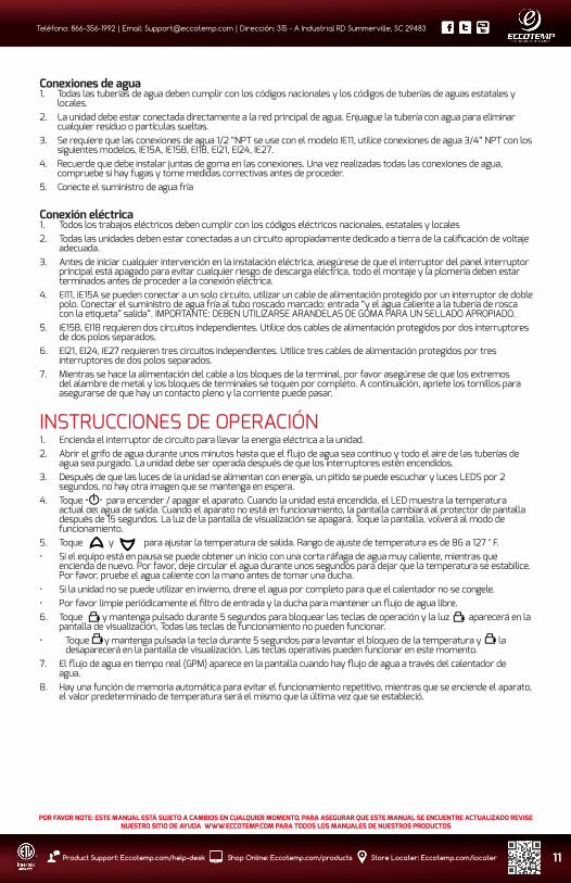
Teléfono: 866-356-1992 | Email: [email protected] | Dirección: 315 - A Industrial RD Summerville, SC 29483
POR FAVOR NOTE: ESTE MANUAL ESTÁ SUJETO A CAMBIOS EN CUALQUIER MOMENTO, PARA ASEGURAR QUE ESTE MANUAL SE ENCUENTRE ACTUALIZADO REVISE NUESTRO SITIO DE AYUDA WWW.ECCOTEMP.COM PARA TODOS LOS MANUALES DE NUESTROS PRODUCTOS
11Product Support: Eccotemp.com/help-desk Shop Online: Eccotemp.com/products Store Locater: Eccotemp.com/locater
Conexiones de agua1. Todas las tuberías de agua deben cumplir con los códigos nacionales y los códigos de tuberías de aguas estatales y
locales.2. La unidad debe estar conectada directamente a la red principal de agua. Enjuague la tubería con agua para eliminar
cualquier residuo o partículas sueltas.3. Se requiere que las conexiones de agua 1/2 “NPT se use con el modelo IE11, utilice conexiones de agua 3/4” NPT con los
siguientes modelos, IE15A, IE15B, EI18, EI21, EI24, IE27.4. Recuerde que debe instalar juntas de goma en las conexiones. Una vez realizadas todas las conexiones de agua,
compruebe si hay fugas y tome medidas correctivas antes de proceder.5. Conecte el suministro de agua fría
Conexión eléctrica1. Todos los trabajos eléctricos deben cumplir con los códigos eléctricos nacionales, estatales y locales2. Todas las unidades deben estar conectadas a un circuito apropiadamente dedicado a tierra de la calificación de voltaje
adecuada.3. Antes de iniciar cualquier intervención en la instalación eléctrica, asegúrese de que el interruptor del panel interruptor
principal está apagado para evitar cualquier riesgo de descarga eléctrica, todo el montaje y la plomería deben estar terminados antes de proceder a la conexión eléctrica.
4. EI11, iE15A se pueden conectar a un solo circuito, utilizar un cable de alimentación protegido por un interruptor de doble polo. Conectar el suministro de agua fría al tubo roscado marcado: entrada “y el agua caliente a la tubería de rosca con la etiqueta” salida”. IMPORTANTE: DEBEN UTILIZARSE ARANDELAS DE GOMA PARA UN SELLADO APROPIADO.
5. iE15B, EI18 requieren dos circuitos independientes. Utilice dos cables de alimentación protegidos por dos interruptores de dos polos separados.
6. EI21, EI24, iE27 requieren tres circuitos independientes. Utilice tres cables de alimentación protegidos por tres interruptores de dos polos separados.
7. Mientras se hace la alimentación del cable a los bloques de la terminal, por favor asegúrese de que los extremos del alambre de metal y los bloques de terminales se toquen por completo. A continuación, apriete los tornillos para asegurarse de que hay un contacto pleno y la corriente puede pasar.
INSTRUCCIONES DE OPERACIÓN1. Encienda el interruptor de circuito para llevar la energía eléctrica a la unidad.2. Abrir el grifo de agua durante unos minutos hasta que el flujo de agua sea continuo y todo el aire de las tuberías de
agua sea purgado. La unidad debe ser operada después de que los interruptores estén encendidos.3. Después de que las luces de la unidad se alimentan con energía, un pitido se puede escuchar y luces LEDS por 2
segundos, no hay otra imagen que se mantenga en espera.4. Toque para encender / apagar el aparato. Cuando la unidad está encendida, el LED muestra la temperatura
actual del agua de salida. Cuando el aparato no está en funcionamiento, la pantalla cambiará al protector de pantalla después de 15 segundos. La luz de la pantalla de visualización se apagará. Toque la pantalla, volverá al modo de funcionamiento.
5. Toque y para ajustar la temperatura de salida. Rango de ajuste de temperatura es de 86 a 127 ° F.• Si el equipo está en pausa se puede obtener un inicio con una corta ráfaga de agua muy caliente, mientras que
encienda de nuevo. Por favor, deje circular el agua durante unos segundos para dejar que la temperatura se estabilice. Por favor, pruebe el agua caliente con la mano antes de tomar una ducha.
• Si la unidad no se puede utilizar en invierno, drene el agua por completo para que el calentador no se congele.• Por favor limpie periódicamente el filtro de entrada y la ducha para mantener un flujo de agua libre.6. Toque y mantenga pulsado durante 5 segundos para bloquear las teclas de operación y la luz aparecerá en la
pantalla de visualización. Todas las teclas de funcionamiento no pueden funcionar.• Toque y mantenga pulsada la tecla durante 5 segundos para levantar el bloqueo de la temperatura y la
desaparecerá en la pantalla de visualización. Las teclas operativas pueden funcionar en este momento.7. El flujo de agua en tiempo real (GPM) aparece en la pantalla cuando hay flujo de agua a través del calentador de
agua.8. Hay una función de memoria automática para evitar el funcionamiento repetitivo, mientras que se enciende el aparato,
el valor predeterminado de temperatura será el mismo que la última vez que se estableció.
CONTINUACIÓN DE MÉTODO Y UBICACIÓN DE LA INSTALACIÓN...

Teléfono: 866-356-1992 | Email: [email protected] | Dirección: 315 - A Industrial RD Summerville, SC 29483
12 Product Support: Eccotemp.com/help-desk Shop Online: Eccotemp.com/products Store Locater: Eccotemp.com/locater
POR FAVOR NOTE: ESTE MANUAL ESTÁ SUJETO A CAMBIOS EN CUALQUIER MOMENTO, PARA ASEGURAR QUE ESTE MANUAL SE ENCUENTRE ACTUALIZADO REVISE NUESTRO SITIO DE AYUDA WWW.ECCOTEMP.COM PARA TODOS LOS MANUALES DE NUESTROS PRODUCTOS
SOLUCIÓN DE PROBLEMASProblemas Causas posibles Correcciones
1. Los accesorios de entrada y salida con fugas
A. guarniciones flojasB. arandela de goma desgastada
A. Ajuste las conexiones.B. Cambie la arandela de goma.
2. Sin LED de señal A.alimentación no conectada.B.LED dañado.
A. Conecte a la unidad.B. Cambie LED.
3. Teclas funcionales no funcionan A. No hay agua que no trabaja fuera de ducha.B. La presión del agua es demasiado baja.C. Tecla o PCB dañados.
A. Abra para obtener agua.B. Abra la válvula para conseguir la presión.C. Cambie tecla o PCB.
4. Agua demasiado caliente A. temperatura demasiado alta.B. El agua fluye demasiado poco.
A.Establezca una temperatura más baja.B.Abra más la válvula
5. Agua demasiado fría A. temperatura demasiado baja.B.El agua fluye demasiado.
A. Establezca una temperatura más alta.B. Reducir el flujo de agua.
6. Reducción de la presión de salida del agua Colador de entrada obstruido o ducha Limpie el filtro y la ducha.
7. LED muestra la temperatura de salida E1 La salida de temperatura es más de 67 ° C / 153 ° F
A. reduzca la temperatura, B. suba el flujo de agua
8. LED exhibe E3 Falla en el sensor de temperatura Póngase en contacto con su distribuidor
9. Indicación de sobrecarga Flujo de entrada de agua es demasiado Reduzca el caudal de entrada de agua
7 y 8 sólo deben ser realizadas por un electricista calificado. Lo mejor es ponerse en contacto con la persona que instaló inicialmente la unidad para pedir ayuda.
VISTA DE EXPOSICIÓN
MANTENIMIENTO NORMALNota: No intente reparar este calentador de agua usted mismo. Llame a una persona de servicio para asistencia. Siempre apague la corriente eléctrica de la unidad. Apague todos los interruptores automáticos que suministran energía al aparato * Tenga en cuenta que algunas unidades están conectadas a múltiples interruptores. Apagar todos los ABASTECIMIENTO DE AGUA Y TODOS LAS TOMAS DE CORRIENTE.
Esta unidad no requiere ningún mantenimiento regular. Sin embargo, para asegurar el flujo de agua constante, se recomienda seguir los siguientes procedimientos.
1. Periódicamente retire la escala y la suciedad que se puede acumular en el aireador del grifo o en el cabezal de la ducha.2. Hay un filtro construido en la pantalla de la conexión de entrada que debe limpiarse de vez en cuando. Por favor, apague el flujo de agua antes de hacer esto.
Pantalla de visualización
Tablero de visualización
Caja de tarjeta de pantalla
Válvula de alivio de presión
Conexión de salida de agua
Conexión de entrada de agua
Cubierta de válvula
Junta de goma
Cubierta impermeable
Grapa de alambre
alambre de la abrazadera
Caja frontal
Protección térmica
Ventilador de radiación
Cámara de calentamiento
Medidor de flujo
Cubierta trasera
Tablero de alimentación principal
Bloque terminal
Placa aislante
Teléfono: 866-356-1992 | Email: [email protected] | Dirección: 315 - A Industrial RD Summerville, SC 29483
POR FAVOR NOTE: ESTE MANUAL ESTÁ SUJETO A CAMBIOS EN CUALQUIER MOMENTO, PARA ASEGURAR QUE ESTE MANUAL SE ENCUENTRE ACTUALIZADO REVISE NUESTRO SITIO DE AYUDA WWW.ECCOTEMP.COM PARA TODOS LOS MANUALES DE NUESTROS PRODUCTOS
13Product Support: Eccotemp.com/help-desk Shop Online: Eccotemp.com/products Store Locater: Eccotemp.com/locater
Sistemas Eccotemp,LLC Informaciónsobre garantía limitadaMODELOS: iE-11 iE-15B iE-15A iE-18 iE-24 iE-27
Eccotemp da garantía de que este producto estará libre de defectos de materiales y mano de obra cuando se instale y se opere de acuerdo con las instrucciones de instalación y funcionamiento de Eccotemp. Esta garantía limitada se extiende al comprador original y los posteriores propietarios, pero sólo mientras el producto permanezca en el lugar de la instalación original. Esta garantía se termina si se mueve o es reinstalado en una nueva ubicación. No existen otras garantías, explícitas o implícitas que no estén en el contenido de esta garantía limitada. Ningún agente, empleado o representante de Eccotemp tiene autoridad alguna para obligar a Eccotemp a dar cualquier garantía en relación con el Producto no contenida en esta garantía limitada. Eccotemp se reserva el derecho y la autoridad para cambiar, modificar o alterar esta garantía en cualquier momento dado.
A excepción de lo expresamente establecido en el presente documento, NO HAY representaciones o garantías, expresa o implícita, incluyendo, sin limitación en cuanto a la comercialización o aptitud para un propósito PARTICULAR CON RESPECTO A CUALQUIER BIEN VENDIDO POR LA PRESENTE. EL RECURSO DEL COMPRADOR SE LIMITA A LA REPARACIÓN O SUSTITUCIÓN de los bienes vendidos, a discreción de ECCOTEMP. ECCOTEMP NO SERÁ RESPONSABLE POR DAÑOS DIRECTOS O INDIRECTOS.
Período de garantía limitada
Esta garantía se extiende por los sistemas de Eccotemp al propietario. Esta garantía entra en vigor en la fecha de instalación del producto o 30 días después de la fecha de compra, lo que ocurra primero, y es efectivo hasta el aniversario que se especifica en dicha fecha de la siguiente manera:
Período de cobertura del elemento
Cámara / elemento de calefacción 3 años Todas las demás piezas 2 años
Cobertura se anula si la unidad se utiliza en un circuito de circulación de agua caliente, en serie con un sistema de circulación o en un sistema de recirculación de la demanda en que no se incorpora.
El propietario es responsable de todos los otros costos relacionados con la reparación tales como mano de obra, transporte, entrega y permisos.Prueba de compra requerida. Los productos reparados estarán cubiertos por esta garantía limitada para el resto del término de la compra original.
Exclusiones
Por favor, consulte el Manual de instalación y Manual de uso y cuidado suministrado con su nuevo producto Sistemas Eccotemp. Esta garantía limitada quedará automáticamente anulada y sin efecto si alguno de los siguientes son determinados Por Eccotemp a ser un factor contribuyente a la falla del producto:
1. El abuso, mal uso, alteración, negligencia o uso indebido.2. incorrecto, mantenimiento, procedimientos destructivos peligrosos o mantenimiento inadecuado.3. Daños causados por reparaciones realizadas por los administradores de sistemas distintos de Eccotemp.4. Instalación en un ambiente corrosivo o de otro modo destructivo.5. Los daños como consecuencia de la congelación dentro de la unidad o alrededor de la tubería.6. La acumulación de incrustaciones.7. Una tensión incorrecta, amplificadores o la presión del agua.8. Actos de fuerza mayor.9. Daños como resultado de su uso con no portátil, no tratada o mal tratada el agua de pozo o agua con altos niveles de pH o
niveles de dureza de más de 12 granos por galón (200 mg / L).10. Dimensionamiento incorrecto para la aplicación.11. Los productos con números de serie originales que han sido removidos o alterados y que no pueden determinarse con.

Teléfono: 866-356-1992 | Email: [email protected] | Dirección: 315 - A Industrial RD Summerville, SC 29483
14 Product Support: Eccotemp.com/help-desk Shop Online: Eccotemp.com/products Store Locater: Eccotemp.com/locater
POR FAVOR NOTE: ESTE MANUAL ESTÁ SUJETO A CAMBIOS EN CUALQUIER MOMENTO, PARA ASEGURAR QUE ESTE MANUAL SE ENCUENTRE ACTUALIZADO REVISE NUESTRO SITIO DE AYUDA WWW.ECCOTEMP.COM PARA TODOS LOS MANUALES DE NUESTROS PRODUCTOS
12. 12. Los actos de Dios, incluyendo, pero no limitados a; incendio, inundación, o un desastre natural.
Este producto no debe ser utilizado como una piscina o un calentador de hidromasaje.
En el caso de que se reconozca un defeco en los sistemas de Eccotemp, mal funcionamiento o falla de conformidad con esta garantía y en base a la aprobación de Eccotemp de reclamación de garantía, Eccotemp Systems, a su discreción única y absoluta, resolverá la reclamación de tal defecto, mal funcionamiento o falta de cumplimiento de esta garantía. Con el fin de hacer una reclamación bajo esta garantía, el propietario debe notificar a Eccotemp del daño del Producto para cumplir con esta garantía.
En virtud de esta garantía, Eccotemp Sistemas sólo proporcionará piezas de cambio como se describe en la “ Período de garantía limitada”. El propietario será responsable de los gastos incurridos incluyendo los costos de mano de obra para dar servicio a la unidad, envío, entrega y manipulación de la pieza de repuesto, el costo de los permisos o materiales necesarios para la reparación, o los costos secundarios producto de daños externos a la unidad que resulten de la falla.
A PESAR DE LO PRESENTADO EN LA GARANTÍA CONSTAN las obligaciones positivas de ECCOTEMP SYSTEMS DETALLADAS EN ESTA GARANTÍA, ECCOTEMP RENUNCIA A TODA GARANTÍA, EXPRESA ni implícita, sobre el producto y su funcionalidad, rendimiento, comerciabilidad, idoneidad para propósitos o propiedad intelectual y derechos. ECCOTEMP RENUNCIA A TODAS LAS OTRAS OBLIGACIONES por su parte y no asume ni autoriza a ninguna otra persona a asumir por SISTEMAS ECCOTEMP OTROS PASIVOS EN RELACIÓN CON EL FUNCIONAMIENTO DEL PRODUCTO. Esta garantía cubre únicamente piezas de recambio y NO CUBRE costo del trabajo o servicios bajo ninguna circunstancia.
Sistemas con daños de cualquier tipo, incluyendo, pero no limitado a, daños incidentales y consecuentes, pueden surgir por medio del presente Acuerdo. Algunos estados no permiten la exclusión o limitación de daños incidentales o consecuentes, por lo que la limitación o exclusión anterior no se aplica en su caso. Esta garantía le otorga derechos legales específicos. Usted también puede tener otros derechos que varían de estado a estado.
VER ALGUNOS DE LOS DEMÁS PRODUCTOS ECCOTEMPCOMPARACIÓN DE PRODUCTOS PARA TODO EL HOGAR

Teléfono: 866-356-1992 | Email: [email protected] | Dirección: 315 - A Industrial RD Summerville, SC 29483
POR FAVOR NOTE: ESTE MANUAL ESTÁ SUJETO A CAMBIOS EN CUALQUIER MOMENTO, PARA ASEGURAR QUE ESTE MANUAL SE ENCUENTRE ACTUALIZADO REVISE NUESTRO SITIO DE AYUDA WWW.ECCOTEMP.COM PARA TODOS LOS MANUALES DE NUESTROS PRODUCTOS
15Product Support: Eccotemp.com/help-desk Shop Online: Eccotemp.com/products Store Locater: Eccotemp.com/locater
BTU
Caudal
Portátil
Fuente de alimentación
Tipo de gas
Ventilación
Presión del agua
Regulador y manguera
Control de temperatura
Garantía
Dimensiones del producto
Dimensiones del paquete
INSTALACIÓN
i12fvi12
SÓLO INTERIORES
74,000
3.6 GPM
No
120 VAC
Disponible en gas natural y LP
2.5 “de ventilación horizontal (Incl)
20-80 PSI
No incluido
Manual 80” - 120”
2 años limitada
15” x 4” x 24” - 30 lbs
17” x 11” x 28” - 32 lbs
VER ALGUNOS DE LOS DEMÁS PRODUCTOS ECCOTEMPCOMPARACIÓN DE PRODUCTOS PARA TODO EL HOGAR
fvi12
SÓLO INTERIORES
80,000
3 GPM
No
120 VAC
Disponible en gas natural y LP
2.5 “de ventilación horizontal (Incl)
20-80 PSI - flujo Activado
No incluido
Automático 80° - 120°
2 años limitada
14” x 5” x 24” - 30 lbs
17” x 11” x 29” - 32 lbs
i12
SÓLO EXTERIORES
140,000
6.8 GPM
No
120 VAC
Disponible en gas natural y LP
Innecesario
20-80 PSI - flujo Activado
No incluido
Automático 90° - 140°
10 años - Intercambiador de calor 5 Años - Repuestos
15” x 5” x 24” - 38 lbs
16” x 7.5” x 26” - 40 lbs
45-H
SÓLO INTERIORES
140,000
6.8 GPM
No
120 VAC
Disponible en gas natural y LP
Se vende por separado
20-80 PSI - flujo Activado
No incluido
Automático 90° - 140°
10 años - Intercambiador de calor 5 Años - Repuestos
15” x 5” x 24” - 38 lbs
16” x 7.5” x 26” - 40 lbs
45-HI
45-H 45-HI

Phone: 866-356-1992 | Email: [email protected] | Address: 315 - A Industrial RD Summerville, SC 29483
Product Support: Eccotemp.com/help-desk Shop Online: Eccotemp.com/products Store Locater: Eccotemp.com/locater
PLEASE NOTE: THIS MANUAL IS SUBJECT TO CHANGE AT ANYTIME, TO ENSURE THIS MANUAL IS UP TO DATE PLEASE VISIT OUR HELP DESKAT WWW.ECCOTEMP.COM FOR ALL OF OUR PRODUCT MANUALS.