phase noise estimation for (d ata bits)
TRANSCRIPT

Improving landfill monitoring programswith the aid of geoelectrical - imaging techniquesand geographical information systems Master’s Thesis in the Master Degree Programme, Civil Engineering
KEVIN HINE
Department of Civil and Environmental Engineering Division of GeoEngineering Engineering Geology Research GroupCHALMERS UNIVERSITY OF TECHNOLOGYGöteborg, Sweden 2005Master’s Thesis 2005:22
Equalizer
Iterative DetectorEstimator
Demapper Deinterleaver
Interleaver LDPC Decoder SlicerSymbol
Mapper
Extended Kalman Filter -
Smoother
Posterior Mapper
Soft Modem
Input (Received Signal)
Output
(Data bits)
Interleaver
Phase Noise Estimation forUncoded/Coded SISO and MIMOSystemsMaster’s Thesis in the program Communication Engineering
ARIF ONDER ISIKMAN
Department of Signal & SystemsChalmers University of TechnologyGothenburg, Sweden 2012Master’s Thesis EX061/2012

The Author grants to Chalmers University of Technology the non-exclusive right topublish the Work electronically and in a non-commercial purpose make it accessible onthe Internet. The Author warrants that he/she is the author to the Work, and warrantsthat the Work does not contain text, pictures or other material that violates copyrightlaw.
The Author shall, when transferring the rights of the Work to a third party (forexample a publisher or a company), acknowledge the third party about this agreement.If the Author has signed a copyright agreement with a third party regarding the Work,the Author warrants hereby that he/she has obtained any necessary permission fromthis third party to let Chalmers University of Technology store the Work electronicallyand make it accessible on the Internet.
Phase Noise Estimation for Uncoded/Coded SISO and MIMO SystemsARIF ONDER ISIKMAN
c© ARIF ONDER ISIKMAN, 2012
Examiner: Assistant Professor Alexandre Graell i Amat
Technical report no EX061/2012Department of Signals & SystemsChalmers University of TechnologySE-41296 GothenburgSwedenTelephone +46 (0) 31-704 195422

Abstract
New generation cellular networks have been forced to support high data rate communi-cations. The demand for high bandwidth data services has rapidly increased with theadvent of bandwidth hungry applications. To fulfill the bandwidth requirement, highthroughput backhaul links are required. Microwave radio links operating at high fre-quency bands are used to fully exploit the available spectrum. Generating high carrierfrequency becomes problematic due to the hardware limitations. Non-ideal oscillatorsboth at the transmitter and the receiver introduces time varying phase noise whichinteracts with the transmitted data in a non-linear fashion. Phase noise becomes adetrimental problem in digital communication systems and needs to be estimated andcompensated. In this thesis receiver algorithms are derived and evaluated to mitigatethe effects of the phase noise in digital communication systems.
The thesis is organized as follows: In Chapter 3 phase noise estimation in single-inputsingle-output (SISO) systems is investigated. First, a hard decision directed extendedKalman filter (EKF) is derived and applied to track time varying phase noise for anuncoded system. Next, the problem of phase noise estimation for coded SISO system isinvestigated. An iterative receiver algorithm performing code-aided turbo synchroniza-tion is derived using the expectation maximization (EM) framework. Two soft-decisiondirected estimators in the literature based on Kalman filtering, the Kalman filter andsmoother with maximum likelihood average (KS-MLA) and the extended Kalman fil-ter and smoother (EKS), are evaluated. Low density parity check (LDPC) codes areproposed to calculate marginal a posteriori probabilities and to construct soft decisionsymbols. Error rate performance of both estimators, the KS-MLA and the EKS, aredetermined and compared through simulations. Simulations indicate that comparisonon the performance of the existing estimators heavily depends on the system parameterssuch as block length and modulation order which are not taken into consideration in theliterature.
In Chapter 4 the thesis focuses on phase noise estimation in multi-input multi-output(MIMO) systems. MIMO technology is commonly used in microwave radio links to im-prove spectrum efficiency. First, an uncoded MIMO system is taken under consideration.A low complexity hard decision directed EKF is derived and evaluated. A new MIMOreceiver algorithm that iterates between the estimator and the detector, based on the EMframework for joint estimation and detection in coded MIMO systems in the presenceof time varying phase noise is proposed. A low complexity soft decision directed ex-tended Kalman filter and smoother (EKFS) that tracks the phase noise parameters overa frame is proposed in order to carry out the maximization step. The proposed EKFSbased approach is combined with an iterative detector that utilizes bit interleaved codedmodulation and employs LDPC codes to calculate the marginal a posteriori probabilitiesof the transmitted symbols, i.e., soft decisions. Numerical investigations show that for awide range of phase noise variances the estimation accuracy of the proposed algorithm

improves at every iteration. Finally, simulation results confirm that the error rate perfor-mance of the proposed EM-based approach is close to the scenario of perfect knowledgeof phase noise at low-to-medium signal-to-noise ratios.


Acknowledgements
I would first like to thank my supervisors Hani Mehrpouyan and Alexandre Graell i Amatfor their support and guidance during the whole thesis process. I highly appreciatetheir attitude towards me. They have taught me how an academic should approachthe problems in the field of research. They have also trusted me and given me a lotof freedom. They respect my independent and somehow arrogant way of performingresearch. I would also like to thank my friends in Communication Engineering MastersProgramme for the discussions and shared ideas. I want to also thank to the employeesat Ericsson for showing me how things are done in industry in a short time.
Thanks also to my family and friends in Turkey for supporting me through all theseyears of studying. I have to thank my Swedish family, Jan and Ann-Charlotte Fonselius,for creating such a nice environment for me at the house which I share with my belovedfriend Kiryl Kustanovich.
Last but not least, I want to thank Olric. I would not be able to finish this thesiswithout him.
Arif Onder Isikman, Goteborg September 7, 2012

Contents
1 Introduction 31.1 Background . . . . . . . . . . . . . . . . . . . . . . . . . . . . . . . . . . . 41.2 Thesis Organization . . . . . . . . . . . . . . . . . . . . . . . . . . . . . . 51.3 Thesis Contributions . . . . . . . . . . . . . . . . . . . . . . . . . . . . . . 5
2 Digital Communicationswith Phase Noise 72.1 Phase Noise Modeling . . . . . . . . . . . . . . . . . . . . . . . . . . . . . 7
2.1.1 Digital Communications in the Presence of Phase Noise . . . . . . 8
3 Phase Noise Estimationfor SISO systems 123.1 Uncoded SISO . . . . . . . . . . . . . . . . . . . . . . . . . . . . . . . . . 12
3.1.1 The Extended Kalman Filter . . . . . . . . . . . . . . . . . . . . . 133.2 Coded SISO . . . . . . . . . . . . . . . . . . . . . . . . . . . . . . . . . . . 15
3.2.1 Expectation Step (E-Step) . . . . . . . . . . . . . . . . . . . . . . . 163.2.2 Maximization Step (M-Step) . . . . . . . . . . . . . . . . . . . . . 173.2.3 LDPC decoder . . . . . . . . . . . . . . . . . . . . . . . . . . . . . 203.2.4 Simulation Results . . . . . . . . . . . . . . . . . . . . . . . . . . . 22
4 Phase Noise Estimationfor MIMO systems 264.1 Uncoded MIMO . . . . . . . . . . . . . . . . . . . . . . . . . . . . . . . . 26
4.1.1 MIMO detection . . . . . . . . . . . . . . . . . . . . . . . . . . . . 284.1.2 The Extended Kalman Filter . . . . . . . . . . . . . . . . . . . . . 284.1.3 Simulation Results . . . . . . . . . . . . . . . . . . . . . . . . . . . 30
4.2 Coded MIMO . . . . . . . . . . . . . . . . . . . . . . . . . . . . . . . . . . 314.2.1 The EM algorithm . . . . . . . . . . . . . . . . . . . . . . . . . . . 324.2.2 E-Step . . . . . . . . . . . . . . . . . . . . . . . . . . . . . . . . . 324.2.3 M-Step . . . . . . . . . . . . . . . . . . . . . . . . . . . . . . . . . 33
i

CONTENTS
4.2.4 The Extended Kalman Filter-Smoother . . . . . . . . . . . . . . . 344.2.5 Iterative Detector . . . . . . . . . . . . . . . . . . . . . . . . . . . 354.2.6 Simulation Results . . . . . . . . . . . . . . . . . . . . . . . . . . . 38
5 Conclusion and Future Work 425.1 Conclusion . . . . . . . . . . . . . . . . . . . . . . . . . . . . . . . . . . . 425.2 Future Work . . . . . . . . . . . . . . . . . . . . . . . . . . . . . . . . . . 43
Bibliography 43
ii

List of Figures
2.1 Wiener phase noise for σ2∆ = 1. . . . . . . . . . . . . . . . . . . . . . . . 9
2.2 16-QAM constellation. . . . . . . . . . . . . . . . . . . . . . . . . . . . . . 92.3 16-QAM constellation affected by AWGN. . . . . . . . . . . . . . . . . . . 102.4 16-QAM constellation rotated by phase noise. . . . . . . . . . . . . . . . . 112.5 Received signal affected by both phase noise and AWGN. . . . . . . . . . 11
3.1 BER vs. Eb/N0 for 16-QAM for various values of σ2∆. . . . . . . . . . . . 14
3.2 BER vs. Eb/N0 for 16-QAM uncoded and coded system without phasenoise . . . . . . . . . . . . . . . . . . . . . . . . . . . . . . . . . . . . . . . 15
3.3 Block diagram of the receiver structure for coded SISO system. . . . . . . 183.4 Tanner graph for Hp in (3.43). . . . . . . . . . . . . . . . . . . . . . . . . 213.5 BER vs. the EM algorithm iterations for 256-QAM coded system with
EKS at Eb/N0 = 16dB for different number of decoder iterations, withand without keeping internal decoder information. . . . . . . . . . . . . . 23
3.6 BER vs. Eb/N0 for 16-QAM coded system with both the EKS and theKS-MLA where σ2
∆ = 10−4 and 3 decoding iteration. . . . . . . . . . . . . 243.7 BER vs. Eb/N0 for 16-QAM coded system with both the EKS and the
KS-MLA where σ2∆ = 3 · 10−4 and 3 decoding iteration. . . . . . . . . . . 24
3.8 BER vs. Eb/N0 for 256-QAM coded system with both the EKS and theKS-MLA where σ2
d = 10−4 and 3 decoding iteration. . . . . . . . . . . . . 25
4.1 BER vs. Eb/N0 for 2x2 uncoded MIMO system with BPSK modulationfor various σ2
∆ values. . . . . . . . . . . . . . . . . . . . . . . . . . . . . . 314.2 Block diagram of the receiver structure. . . . . . . . . . . . . . . . . . . . 354.3 BER performance of the EM-based algorithm with DA(14) estimator. . . 384.4 FER performance of the EM-based algorithm at several iterations where
σ2∆ = 5 · 10−5, and DA initial estimation with pr = 14. . . . . . . . . . . . 39
4.5 MSE performance of the EM-based algorithm, and DA initial estimationwith pr = 14 for several phase noise processes and EM algorithm iterations. 39
iii

LIST OF FIGURES
4.6 FER performance of the EM-based algorithm, and DA initial estimationwith pr = 14 for several number of decoder iterations, σ2
∆ = 5 · 10−4. . . . 404.7 FER performance of the EM-based algorithm at several iterations where
σ2∆ = 5 · 10−4, DA initial estimation with pr = 14, and R = 1/2 rate code. 41
iv

Acronym
APP a posteriori probability
AWGN additive white gaussian noise
BER bit error rate
BICM bit interleaved coded modulation
BS base station
BSC base station controller
DA data aided
EKF extended Kalman filter
EKS extended Kalman filter-smoother (SISO)
EKFS extended Kalman filter-smoother (MIMO)
EM expectation maximization
FER frame error rate
KS Kalman filter-smoother (SISO)
KS-MLA Kalman filter-smoother with maximum likelihood average
LDPC low-density parity-check
LOS line-of-sight
LLF log likelihood function
LLR log likelihood ratio
LS least square
1

LIST OF FIGURES LIST OF FIGURES
MAP maximum a posteriori
MIMO multi-input multi-output
ML maximum likelihood
MMSE minimum mean square error
MSC master switching center
MSE mean square error
QAM quadrature amplitude modulation
SDMA space division multiple access
SISO single-input single-output
SNR signal to noise ratio
VCO voltage controlled oscillator
WLS weighted least square
2

1Introduction
In recent years the demand for high bandwidth data services has increased with theevolution of the third generation (3G) and fourth generation (4G) cellular networks [1].Rapid escalation in the use of bandwidth hungry devices also increases the throughputrequirements of the base station (BS), base station controller (BSC) and master switchingcenter (MSC), which are the fundamental components of a cellular network. The userconnects to the network through the BS. Each BS is connected to a BSC via a wiredor a wireless link. The BSC routes the data from the BS to the MSC and controls thefunctionality of the BS. The MSC holds all the network information and controls allcalls and data management functionalities. In other words, the MSC is the brain of anycellular network. The portion of a wireless mobile network from the BS to the MSC iscalled as backhaul network.
The backhaul links serves the medium to carry traffic from the BS to the MSC via theBSC. The point-to-point microwave radio links are commonly used in backhaul networks.They are cost efficient and can be deployed rapidly. Microwave radio transmission isoperated at certain frequency bands. Lower bands such as 7, 18, 23 and 35GHz havebetter radio propagation characteristics. On the other hand, these frequency bands failto provide sufficient bandwidth since the spectrum is mostly allocated. With the releaseof the E-Band, 10GHz of bandwith in the spectrum at 70GHz (71-76GHz) and 80GHz(81-86GHz) have been made available for point-to-point microwave links. To meet highdata rate requirements point-to-point microwave systems are equipped with multipletransmit and multiple receive antennas. Line-of-sight (LOS) multi-input multi-output(MIMO) systems are effectively used for backhaul networking [2].
Local oscillators are utilized to carry the baseband signal to the operating band.Due to the hardware limitations, every oscillator suffers from an instability of its phase,resulting in phase noise [3]. Phase noise can dramatically limit the performance of awireless communication system if left unaddressed [4]. Phase noise interacts with thetransmitted symbols both at the transmitter and the receiver side in a non-linear manner
3

1.1. BACKGROUND CHAPTER 1. INTRODUCTION
and significantly distorts the received signal. Digital signal processing algorithms need tobe employed to achieve synchronous transmission in the presence of phase noise. Severalalgorithms are proposed for single-input single-output (SISO) systems to mitigate theeffect of time varying phase noise [5–9]. In the case of LOS-MIMO systems, each transmitand receive antenna is equipped with a different oscillator since the antennas are placedfar apart. Similarly, in the case of multi-user MIMO systems or space division multipleaccess (SDMA) systems independent oscillators are used by different users to transmittheir data to common receiver [10]. As a result, a single oscillator cannot be employedand phase noise compensation algorithms proposed for SISO systems are not directlyapplicable to MIMO systems.
1.1 Background
Achieving channel capacity was seen far from reality until two decades ago. The in-troduction of turbo codes [11] and the rediscovery of low-density-parity-check (LDPC)codes [12] has demonstrated the power of the iterative processing paradigm in improv-ing the performance of communication systems and in operating close to the theoreticallimits. Subsequently, the iterative coding structure has been applied to facilitate andimprove many functions including synchronization. Parameter estimation can be per-formed jointly with data detection in an iterative fashion. It is well-known that theapplication of turbo codes and LPDC codes improves the data detection process at thereceiver, which in turn can be applied to improve the performance of decision-directedestimators. The improved estimation and tracking accuracy allows for more accuratecompensation of impairments such as time varying phase noise at the receiver which canalso improve data detection. Thus, by jointly performing data detection and estimation,the performance of wireless communication systems can be significantly improved. Thisapproach, known as “turbo synchronization”, was initially proposed in [13] and has sincebeen formalized in [14] with the use of the expectation-maximization (EM) framework[15].
In [16], different frameworks for turbo synchronization based on the gradient methodand the sum-product algorithms are studied. This work is extended to the problemof estimation of time varying phase noise for SISO systems in [8]. In [8], based onthe assumption of small phase noise values within each block and removing the datadependency from the observed signal, the tracking is carried out via a modified EM-based algorithm that applies a soft decision-directed linearized Kalman Smoother. Inaddition, to enhance phase noise tracking performance for very high phase noise vari-ances, [8] proposes to employ a maximum-likelihood (ML) estimator in conjunction witha Kalman smoother, labeled as (KS-MLA). A soft decision-directed extended Kalmanfilter-smoother (EKS) is also suggested to provide phase noise estimation. However, theperformance of the KS-MLA degrades with increasing block length. More importantly,the linearization applied in [8] is not applicable to MIMO systems and the estimationperformance of the proposed tracking algorithm is not investigated.
MIMO technology allows communication systems to more efficiently use the avail-
4

1.2. THESIS ORGANIZATION CHAPTER 1. INTRODUCTION
able spectrum [17],[18]. Bit-interleaved-coded-modulation (BICM) is one of the popularschemes that enables communication systems to fully exploit the spectrum efficiencypromised by MIMO technology [19, 20]. However, the performance of MIMO systemsdegrades dramatically in the presence of synchronization errors. Code-aided synchro-nization based on the EM framework for joint channel estimation, frequency and timesynchronization for a BICM-MIMO system is proposed in [21]. However, in [21], the syn-chronization parameters are assumed to be constant and deterministic over the lengthof a block which is not a valid assumption for time varying phase noise.
A Wiener filter approach that applies spatial correlation to improve phase noiseestimation in MIMO systems is proposed in [22]. However, the proposed solution is onlyapplicable to uncoded MIMO systems and the algorithm in [22] introduces significantoverhead to phase noise estimation process since it requires frequent transmission oforthogonal pilot symbols. The problem of joint data detection and phase noise estimationfor coded MIMO systems over block fading channels is still unaddressed and will be themain focus of this thesis.
1.2 Thesis Organization
In Chapter 2 the phase noise model is introduced and digital communication system forSISO systems over the additive white Gaussian noise (AWGN) channel affected by phasenoise is presented.
In Chapter 3 the performance of both uncoded and coded SISO systems affectedby phase noise are investigated. The iterative code-aided EM-based approach used in[8] is modified and derived analytically. The EM-based algorithm is implemented andits components are explained in detail. Two estimators that are proposed in [8], theKS-MLA and the EKS, are evaluated and their performances are compared against oneanother.
In Chapter 4, the MIMO system model for both uncoded and the coded MIMOsystems over Rician fading channels in the presence of phase noise is described in detail.An iterative joint phase noise estimation and data detection algorithm based on the EMframework is derived analytically. A low complexity extended Kalman filter-smoother(EKFS) is proposed to estimate the time varying phase noise processes of each oscillator.BICM scheme is used to decrease the detection complexity. The performance of theproposed algorithm is investigated via computer simulations.
In Chapter 5 conclusion and future research directions are discussed.
1.3 Thesis Contributions
The primary contributions of this thesis are summarized as follows:
• The system model for both uncoded SISO and uncoded MIMO systems in thepresence of phase noise are outlined in detail and an extended Kalman filter with
5

1.3. THESIS CONTRIBUTIONS CHAPTER 1. INTRODUCTION
symbol-by-symbol feedback is proposed for each system. The error rate perfor-mance of the proposed estimators are investigated through numerical results.
• The iterative code-aided EM-based algorithm proposed in [8] for coded SISO sys-tems is modified and derived analytically. Moreover, the performances of twoestimators, the KS-MLA and the EKS, are numerically compared with the help ofcomputer simulations.
• An EM-based receiver is proposed to perform iterative joint phase noise estimationand data detection for BICM-MIMO systems.
• It is analytically demonstrated that a computationally efficient EKFS can be ap-plied to carry out the maximization step of the EM algorithm.
• A new low complexity soft decision-directed EKFS for tracking phase noise overthe length of a frame is proposed and the filtering and smoothing equations arederived.
• Extensive simulations are carried out for different phase noise variances to showthat the performance of a MIMO system employing the proposed receiver structureis very close to the ideal case of perfect knowledge of phase noise. Simulation resultsdemonstrate that error rate performances of a 2×2 LOS-MIMO system using theproposed EM-based receiver is very close to that of the perfectly synchronizedsystem for low-to-medium signal-to-noise ratios. It is also shown that the meansquare-error (MSE) of the phase noise estimates improves with every EM iteration.
6

2Digital Communications
with Phase Noise
2.1 Phase Noise Modeling
In wireless communication systems, the baseband signal is multiplied by a high frequencysine wave to operate at a certain frequency band, called carrier frequency. Local oscil-lators produce the carrier frequency waveforms. Phase-Locked Loop (PLL) [23] is themajor phase recovery block in a communication system. PLL calculates the phase dif-ference between the input and the output signal. The difference is then filtered by a lowpass filter and applied to the voltage controlled oscillator (VCO). The controlled voltageon the VCO changes the oscillator frequency to minimize the phase difference of theinput and the output signal. However, the output of the VCO circuit is a non-ideal sinewave due to some hardware limitations. The power spectrum of the output signal is notstrictly concentrated at the carrier frequency. The instantaneous output of a oscillatoris given by [24]
V (t) = V0(1 +A(t)) exp(j(2πfct+ θ(t))
)(2.1)
where fc denotes the carrier frequency, V0 denotes the amplitude, A(t) is amplitudenoise and θ(t) is phase noise. Demir et. al. show in [3] that amplitude noise decays overtime, since the system stabilizes itself. The amplitude noise may thus be ignored andthe normalized oscillator output signal can be written as
V (t) = e(j2πfct)e(jθ(t)). (2.2)
The oscillator phase noise can be seen as a widening of the spectral peak of theoscillator. The frequency domain single-sideband phase noise power, L(f) is defined asthe ratio of the noise power in a 1Hz sideband at an offset f Hertz away from the carrier,PSSB, to the total signal power, Pc.
7

2.1. PHASE NOISE MODELINGCHAPTER 2. DIGITAL COMMUNICATIONS
WITH PHASE NOISE
Since we have no absolute time reference, the phase disturbances accumulate overtime and can be represented by
θ(t) =
∫ t
0υ(s)ds (2.3)
where υ(t) is a white Gaussian process with a constant power spectral density (PSD).Then, the phase noise process can be modeled as a Wiener process and the oscillatorpower spectrum is a Lorentzian, given by [3]
L(f) =1
πf3dB
1
1 +(
ff3dB
)2 (2.4)
where f3dB denotes the 3dB bandwidth. It is seen that the spectrum is characterized bya single parameter, f3dB. The phase noise process is sampled every Ts seconds, samplingtime interval. Then, the discrete time phase noise process is defined as,
θ(k) , θ(kTs), (2.5)
and can be modeled as a random walk in accordance with 2.3, i.e. discrete-time Wienerprocess [3]
θ(k) = θ(k − 1) + ∆(k). (2.6)
In (2.6), the innovation term, ∆(k) is a discrete zero-mean Gaussian random variablewith variance σ2
∆, denoted as N(0, σ2
∆
). The phase noise innovation variance is given
by [3]
σ2∆ = 4πf3dBTs. (2.7)
Note that the discrete innovation process is also white,
E(∆(k)∆(l)) = 0, k 6= l. (2.8)
In Fig. 2.1 a realization of the discrete time Wiener phase noise process is plotted.
2.1.1 Digital Communications in the Presence of Phase Noise
At the transmitter, a group of data bits are modulated onto an M -point quadratureamplitude modulation (M -QAM) constellation Ω, displayed in Fig. 2.2. Symbols arethen transmitted through an AWGN channel. In a communication system without thephase noise disturbances the received signal at time k is given by
y(k) = s(k) + w(k) (2.9)
where y(k) is the received signal, s(k) is the complex transmitted symbol, w(k) is thezero-mean AWGN with variance σ2
w/2 per dimension, i.e. w(k) ∼ NC(0, σ2
w
), as shown
in Fig. 2.3.
8

2.1. PHASE NOISE MODELINGCHAPTER 2. DIGITAL COMMUNICATIONS
WITH PHASE NOISE
Figure 2.1: Wiener phase noise for σ2∆ = 1.
Figure 2.2: 16-QAM constellation.
9

2.1. PHASE NOISE MODELINGCHAPTER 2. DIGITAL COMMUNICATIONS
WITH PHASE NOISE
Figure 2.3: 16-QAM constellation affected by AWGN.
The received signal is also effected by time varying phase noise both at transmitterand receiver. Let θ[t](k) and θ[r](k) denote the discrete time phase noise sample attransmitter and receiver, respectively. The received signal at time k is given by
y(k) = (s(k)ejθ[t](k) + w(k))ejθ
[r](k) (2.10)
= s(k)ej(θ[t](k)+θ[r](k)) + w(k) (2.11)
= s(k)ejθ(k) + w(k) (2.12)
where w(k) , w(k)ejθ[r](k) is the rotated noise sample, and ejθ(k) is the total phase noise
process. Note that rotation on the circular symmetric additive noise does not changethe statistical properties, i.e., w(k) ∼ NC
(0, σ2
w
). The innovation of total phase noise
process will have a zero-mean Gaussian distribution and its variance will be the sum of
the variances, ∆(k) ∼ N(
0, σ2∆[t] + σ2
∆[r]
)where σ2
∆[t] and σ2∆[r] denote the innovation
variance of the phase noise process at the transmitter an at the receiver, respectively.The total phase noise process rotates the signal constellation as displayed in Fig 2.4.
The received signal which is affected by the AWGN and rotated by the phase noise isshown in Fig. 2.5.
10

2.1. PHASE NOISE MODELINGCHAPTER 2. DIGITAL COMMUNICATIONS
WITH PHASE NOISE
Figure 2.4: 16-QAM constellation rotated by phase noise.
Figure 2.5: Received signal affected by both phase noise and AWGN.
11

3Phase Noise Estimation
for SISO systems
The main focus of this thesis will be on the phase noise estimation for coded MIMOsystems. In this chapter, to better understand the effect of phase noise, the problemof phase noise estimation for SISO systems over AWGN channel is investigated. It isassumed that perfect frame synchronization and phase recovery are performed at thebeginning of each frame by transmitting sufficient number of pilot symbols. Therefore,the problem under consideration for SISO systems is simplified to the problem of phasenoise estimation before investigating the problem for coded MIMO systems. First, anuncoded SISO system is taken under consideration in Sec. 3.1. An extended Kalmanfilter (EKF) is suggested to track time varying phase noise and the set of equationsfor the EKF is derived. In Sec. 3.2, the problem of joint phase noise estimation anddetection for a coded SISO system is discussed. An algorithm is analytically derived fromthe EM framework and is applied to iteratively solve the problem. The enhancementof the LDPC codes and the Kalman filters into the EM-based algorithm is explained indetail.
3.1 Uncoded SISO
In order to de-rotate the signal space and to achieve synchronous communication, timevarying phase noise process should be estimated. Since the parameter to be estimated isnot deterministic, an estimator based on the Bayesian approach should be used [25]. Inthe Bayesian approach, prior knowledge about the random parameter is also taken intoaccount. This approach is commonly used for the systems which can be represented witha dynamical model. Kalman filtering can be considered as a sequential minimum meansquare error (MMSE) estimator which works according to the Bayesian framework.
The received signal in (2.12) and the phase noise process are used to construct a
12

3.1. UNCODED SISOCHAPTER 3. PHASE NOISE ESTIMATION
FOR SISO SYSTEMS
state space signal model. The state and observation equations at time k are given as
State: θ(k) = θ(k − 1) + ∆(k), (3.1)
Observation: y(k) = s(k)ejθ(k) + w(k), (3.2)
where y(k) is the received signal, s(k) is the complex transmitted symbol belonging tothe M -QAM constellation, θ(k) is the phase noise value, w(k) is the additive complexGaussian noise with variance σ2
w and ∆(k) is the phase noise innovation, which is assumedto be Gaussian distributed with variance σ2
∆. Since the observation equation is nonlinear,a hard decision-directed EKF is used instead [25]. The observation equation can berewritten as
y(k) = z(θ(k)) + w(k), (3.3)
where the nonlinear function z(.) is defined as
z(θ(k)) , s(k)ejθ(k). (3.4)
In (3.4), s(k) is the hard decision of the transmitted symbol at time instance k. Note thatfor uncoded SISO systems hard decision symbol, s(k), is obtained by the demodulatorat each time instance. Next, s(k) is input to the hard decision-directed EKF at eachtime instance. In other words, decision feedback is performed symbol-by-symbol. TheEKF provides phase noise estimate, θ(k).
3.1.1 The Extended Kalman Filter
The EKF first predicts the mean and the minimum prediction MSE of the state ahead,θ (k|k − 1) and P (k|k − 1), respectively, given the previous values. Then, the EKF up-dates the estimates with the observation and computes the mean and the minimum MSEof a posteriori state estimate, θ(k|k) and P (k|k), respectively. The Kalman gain, K(k),indicates the amount of correction required for an observation sample. Since z(θ(k)) isa nonlinear function, it is linearized with a first-order Taylor expansion. Therefore, z(k)denotes the Jacobian of z(θ(k)) with respect to θ.
The first and the second moments of the state ahead are predicted as
θ(k|k − 1) = θ(k − 1|k − 1) (3.5)
P (k|k − 1) = P (k − 1|k − 1) + σ2∆. (3.6)
After the observation, the posteriori state estimate statistics are updated as
θ(k|k) = θ(k|k − 1) + <K(k)(y(k)− z(θ(k|k − 1))) (3.7)
P (k|k) = (1−<K(k)z(k))P (k|k − 1), (3.8)
where the Kalman gain is determined as
K(k) = P (k|k − 1)z(k)H(C + z(k)P (k|k − 1)z(k)H
)−1, (3.9)
13

3.1. UNCODED SISOCHAPTER 3. PHASE NOISE ESTIMATION
FOR SISO SYSTEMS
the Jacobian of z with respect to θ is given by
z(k) =∂z(θ(k))
∂θ(k)
∣∣∣θ(k|k−1)
= jz(θ(k)). (3.10)
In (3.9), C is the observation noise variance, given by
C =σ2w
2+ j
σ2w
2. (3.11)
The EKF needs to be properly initialized to compute θ(1|0) and the MSE P (1|0).It is assumed that a sufficient number of pilots is used for frequency, frame and phasesynchronization at the beginning of the frame. Therefore, there is no phase shift of thefirst received signal i.e. θ(1|0) = 0. Moreover, at the first time instant, the minimumprediction MSE is set to P (1|0) = σ2
∆ since this error amounts to the estimation of θ(0|0)without any data.
The EKF is applied for different phase noise innovation variance values. The bit errorrate (BER) performance of the system is investigated. BER vs. Eb/N0 for 16-QAM isshown in Fig. 3.1. It can be seen that as Eb/N0 increases, the EKF performs better andcan track phase noise processes with higher variances.
Figure 3.1: BER vs. Eb/N0 for 16-QAM for various values of σ2∆.
14

3.2. CODED SISOCHAPTER 3. PHASE NOISE ESTIMATION
FOR SISO SYSTEMS
Figure 3.2: BER vs. Eb/N0 for 16-QAM uncoded and coded system without phase noise
3.2 Coded SISO
In coded SISO systems, the data bits are first encoded with an LDPC encoder. Then,the encoded bits are modulated onto complex symbols from an M -QAM constellationM and transmitted through the AWGN channel. The phase noise process should beestimated in order to de-rotate the signal space.
Channel coding adds redundant bits to protect information bits and to correct erro-neous bits. A rate R = 7/8 regular LDPC encoder from the NASA Goddard technicalstandard [26] is used. It is a regular code with variable node degree 4 and check nodedegree 32. The BER vs. Eb/N0 for both uncoded and coded systems without phasenoise is shown in Fig. 3.2. Data bits are mapped to 16-QAM symbols. As expected,very low BERs can be achieved with channel coding at medium and high Eb/N0 levels.
In a coded SISO system in the presence of phase noise, decoding and phase noiseestimation can be performed jointly in an iterative way to complement one another. TheEM framework is used in [16] to estimate the constant phase offset. In [8], a modifiedEM-based algorithm is suggested to estimate time varying phase noise. The trackingis performed by both an extended Kalman filter and smoother (EKS) and a linearizedKalman filter and smoother with maximum-likelihood average (KS-MLA). The MLAalgorithm removes the phase noise average over the frame. In [8], the modified EM-basedalgorithm is not derived analytically. In the following, we demonstrate analytically howan EM-based algorithm can be utilized for code-aided synchronization. The performanceof the proposed estimators is investigated numerically.
15

3.2. CODED SISOCHAPTER 3. PHASE NOISE ESTIMATION
FOR SISO SYSTEMS
First, recall that the signal model and the phase noise model for the uncoded SISOsystem is given by
θ(k) = θ(k − 1) + ∆(k)
y(k) = s(k)ejθ(k) + w(k).
Let Lf denote the number of symbols in one frame. We define the vectors
y , [y(1), y(2), . . . , y(Lf )]T (3.12)
s , [s(1), s(2), . . . , s(Lf )]T (3.13)
θ , [θ(1), θ(2), . . . , θ(Lf )]T . (3.14)
Given the observation vector, y, the maximum a posteriori (MAP) estimate of θ isgiven by
θ = arg maxθ
ln p(y|θ) + ln p(θ) (3.15)
where p(y|θ) =∑
s
p(s)p(y|s,θ) is the a priori probability of parameters θ.
The EM framework is an iterative approach to solve an estimation problem wherethe observation, y, depends not only on the parameter to be estimated, θ, but alsoon some nuisance parameter, s. Note that transmitted symbols, s, and phase noise θare independent. The EM algorithm iteratively maximizes the conditional a posteriori
expectation, Es
ln p(y|s,θ)|y,θ(i−1)
+ ln p(θ), where ln f(y|s,θ) is the conditional log
likelihood function (LLF) and E. denotes the expectation operator. In the expectation
step the block of previous phase noise estimates, θ(i−1)
, is kept fixed and it is updatedin the maximization step.
The EM framework for the ith iteration is defined by [16]
Expectation step: Q(θ|θ(i−1)
), Es
ln p(y|s,θ)|y,θ(i−1)
+ ln p(θ) (3.16)
Maximization step: θ(i)
= arg maxθ
Q(θ|θ(i−1)
). (3.17)
The EM algorithm has been shown to converge to the MAP solution if it is accuratelyinitialized.
3.2.1 Expectation Step (E-Step)
Given the transmitted data and the phase noise process, the received signal has a Gaus-sian distribution. After taking logarithm and dropping constant terms, the conditionalLLF is given by
ln p(y|s,θ) ∝ −2<Lf∑k=1
y(k)s∗(k)e−jθ(k). (3.18)
16

3.2. CODED SISOCHAPTER 3. PHASE NOISE ESTIMATION
FOR SISO SYSTEMS
Taking the conditional expectation over s, given y and θ(i−1)
, equation for the expecta-tion step can be written as
Q(θ|θ(i−1)
)= −2<
Lf∑k=1
α(k)∗y(k)ejθ(k) + ln p(θ), (3.19)
where the weighted or soft symbol α(k) is defined as
α(k) ,∑al∈M
alp(s(k) = al|y, θ
(i−1)). (3.20)
In (3.20),p(s(k) = al|y, θ(i−1)
) are the marginal a posteriori symbol probabilities (APPs)of the transmitted symbol. For 16-QAM, if Gray mapping is used, (3.20) can be com-puted as
α(k) = β1(k)(2− β2(k))− jβ3(k)(2− β4(k)), (3.21)
where
βi(k) = tanhLi(k)
2(3.22)
and Li(k) is the log likelihood ratio (LLR) of the a posteriori probability of the i th bitof the symbol at time instant k, bi(k). The LLR is defined as
Li(k) = logp(bi(k) = 1|y, θ(i−1)
)
p(bi(k) = 0|y, θ(i−1)). (3.23)
The block diagram of the receiver structure is shown in Fig. 3.3 where superscript(i) denotes the iteration of the EM algorithm. The LLRs are first computed by a softdemapper (demodulator). Then, they are passed to the LDPC decoder. Next, the LDPCdecoder runs a sufficient number of iterations to achieve more accurate LLRs. After that,the LLRs computed by the LDPC decoder are modulated into soft symbols according to(3.21) by a soft mapper. As a result, the expectation step computes the block of APPsdenoted as
α , [α(1), α(2), . . . , α(Lf )]T . (3.24)
3.2.2 Maximization Step (M-Step)
The maximization step maximizes Q(θ|θ(i−1)
)in (3.17) with respect to θ. Since the
system can be modeled in a state-space form, the solution can be given by Kalmanfiltering. The Kalman filter is an optimal MMSE estimator which can be considered as
17

3.2. CODED SISOCHAPTER 3. PHASE NOISE ESTIMATION
FOR SISO SYSTEMS
LDPC Decoder
Extended Kalman Filter -
Smoother
Input (Received Signal)
Output (Data bits)
X Soft Demapper
Soft Mapper
Slicer
LLRs
LLRs
Figure 3.3: Block diagram of the receiver structure for coded SISO system.
a MAP estimator [25]. Then, a decision directed Kalman filter where the transmittedsymbol vector, s, is replaced by the soft decision symbol vector, α, estimates θ as
θ = arg maxθ
ln p(y|θ, s = α) + ln p(θ). (3.25)
By setting s = α, the conditional LLF in (3.18) can be rewritten as
ln p(s|s = α,θ) ∝ 2<Lf∑k=1
y(k)α∗(k)e−jθ(k). (3.26)
Using (3.26) in (3.25) we achieve (3.19) which is the function to be maximized in theM-step. As a result, a decision directed Kalman filter can be used to carry the M-step.
In [8], two soft decision-directed Kalman filters, the KS-MLA and the EKS, areproposed. In the following, two estimators will be explained.
The Kalman Filter and Smoother with Maximum Likelihood Average
The KS-MLA proposes a new observation equation which is a linear function of θ. As-suming that α(k) = s(k), the KS-MLA first removes the data dependency from themeasurement via
ε(k) = Imy(k)α∗(k) (3.27)
18

3.2. CODED SISOCHAPTER 3. PHASE NOISE ESTIMATION
FOR SISO SYSTEMS
where ε(k) is the new observation equation. Then, the KS-MLA assumes that the phasenoise values are small enough such that
sin θ ≈ θ (3.28)
cos θ ≈ 1. (3.29)
Subsequently, new observation equation is given by
ε(k) = =y(k)<α(k) − <y(k)=α(k) (3.30)
= u(k)θ(k) + v(k), (3.31)
where
u(k) = <s(k)<α(k)+ =s(k)=α(k) (3.32)
= ‖ α(k) ‖2, (3.33)
and
v(k) = <α(k)=w(k)+ =α(k)<w(k), (3.34)
is a zero mean Gaussian random variable with variance σ2v = Esσ
2w/2 and Es is the
average symbol energy. Since the observation equation is linear, a regular Kalman filterand smoother (KS) can be used. Note that the new observation equation does notdepend on the complex transmitted symbol. Instead, it is a function of the amplitudesquare of the soft symbol.
Phase noise process reaches large values within a block. Depending on σ2∆ and Lf ,
it has a nonzero average over the block. The MLA algorithm estimates the ML averageof the phase noise process over each block and removes it from each received block, y,at the input of KS. Then, the parameter to be estimated is given by
ψ(k) = θ(k)− θavg (3.35)
where
θavg = arg
Ns∑k=1
y(k)α(k)∗. (3.36)
The MLA algorithm is directly embedded into the EM framework and performed beforethe estimator in the M-step.
Extended Kalman Filter and Smoother
Second estimator proposed in [8] is the soft decision-directed EKS. The observationequation in (3.2) is a nonlinear function of θ. Therefore, a suboptimal decision directed
19

3.2. CODED SISOCHAPTER 3. PHASE NOISE ESTIMATION
FOR SISO SYSTEMS
EKS is used to track the phase noise process in [8]. The state and observation equationsat time k are given as
State: θ(k) = θ(k − 1) + ∆(k) (3.37)
Observation: y(k) = α(k)ejθ(k) + w(k). (3.38)
Note that (3.2) and (3.38) are similar. We can rewrite the observation equation as
y(k) = zc(θ(k)) + w(k), (3.39)
where zc stands for the nonlinear function for the coded system. The EKS approximateszc as
zc(θ(k)) ≈ zc(θ(k|k − 1)) +∂zc∂θ(k)
∣∣∣θ(k|k−1)
(θ(k)− θ(k|k − 1)), (3.40)
where θ(k|k − 1) is the estimate of θ(k) based on the previous data.The EKS first filters the received signal and estimates the block of parameters. Af-
terwards, it smooths the estimations with a backward recursion. It is initialized withstate estimate θ(1|0) = 0 and a posteriori MSE P (1|0) = σ2
∆. The filtering equations
compute θ(k) and P (k),k = 2,3, . . . ,Ns in a recursive fashion according to (3.5-3.11)where z(θ(k)) is replaced by zc(θ(k)).
The smoother runs a backward recursion to find better estimates of the parameterblock. We will use subscript s to refer to smoothing. k+ denotes the sequence from k toLf . The set of equations for smoothing are given by
θs(k|k+) = θ(k|k) + P (k|k)P (k + 1|k)−1(θs(k + 1|k + 1+)− θ(k|k)) (3.41)
Ps(k|k+) = P (k|k) + P (k|k)P (k + 1|k)−1
×(Ps(k + 1|k + 1+)− P (k + 1|k))(P (k|k)P (k + 1|k)−1)T(3.42)
3.2.3 LDPC decoder
LDPC codes are linear block codes that have a sparse parity check matrix Hp. Theinput of the LDPC decoder are the LLRs that are computed by the soft demapper(demodulator). The output of the LDPC decoder are the updated LLRs that will beused by the soft mapper (modulator).
An example of a parity check matrix of a (7,4) irregular block code, i.e. the numberof 1’s in each row and in each column is not constant, is given by
Hp =
1 1 1 0 1 0 0
1 0 1 1 0 1 0
1 1 0 1 0 0 1
. (3.43)
The corresponding Tanner graph is shown in Fig. 3.4. There are 7 variable nodes and 4check nodes for Hp. Let k = 1,2,3 an l = 1,2, . . . ,7 be the index of the rows and columns
20

3.2. CODED SISOCHAPTER 3. PHASE NOISE ESTIMATION
FOR SISO SYSTEMS
of Hp, respectively. If Hp[k,l] is 1, then there exists a connection between the check nodek and the variable node l. Note that the information exchange is done in two ways foreach connection, one from variable node to check node and one for the check node tovariable node.
Figure 3.4: Tanner graph for Hp in (3.43).
The LDPC decoder runs the sum product algorithm to estimate the LLRs of thetransmitted bits. It computes the LLR of each path from variable nodes to check nodes,and from check nodes to variable nodes iteratively. L(cl) denotes the LLR of the lth bitof the transmitted codeword c. Let L(rkl) denote the LLR that belongs to the connectionin the direction of check node k to variable node l. Similarly, L(qlk) denotes the LLRof the same connection in the opposite direction. An example is also shown in Fig. 3.4.L(Ql) denotes the updated LLR of the lth bit of the transmitted codeword. The sumproduct algorithm is performed as follows
L(rkl) = 2atanh∏
l′∈Vk\l
tanh(1
2L(ql′k)
), (3.44)
L(qlk) = L(cl) +∑
k′∈Cl\k
L(rk′l), (3.45)
L(Ql) = L(cl) +∑k′∈Cl
L(rk′l), (3.46)
where Vk\l represents the set of indexes of all the variable nodes connected to the checknode k except for the variable node l. Similarly, Cl\k represents the set of indexes ofall the check nodes connected to the variable node l except for the check node k. Forexample, if k = 2 and l = 4, V2\4 = 1,3,6, C4 = 2,3 and C4\2 = 3.
Improving the speed of the algorithm
L(qlk) should be initialized for the first iteration. Normally, it is initialized with theinput LLRs as
L(qlk) = L(cl). (3.47)
21

3.2. CODED SISOCHAPTER 3. PHASE NOISE ESTIMATION
FOR SISO SYSTEMS
As suggested in [16], instead of initializing with the input LLRs, L(qlk) is initializedby the last update of it from the latest EM algorithm iteration. Thus,
L(qlk) = L(qlk)(i−1) (3.48)
where (i) denotes the algorithm iteration. It is seen that significant complexity reductioncan be achieved with negligible degradation in BER with this approximate version. Thenumber of the decoder iterations can be reduced and the number of the EM algorithmiterations can be increased. Since the complexity heavily depends on the number ofdecoder iterations, the overall complexity is much less than that of the original EM-based algorithm.
3.2.4 Simulation Results
First, the advantage of keeping internal information at the decoder is investigated forthe 256-QAM system with the EKS. In Fig. 3.5, the BER is calculated for each EMiteration for different number of decoding iterations with and without keeping internalinformation at the decoder for a fixed Eb/N0 = 16dB. The dashed lines represent thealgorithm where the LDPC decoder is reinitialized between each iteration of the EMalgorithm. In Fig. 3.5, the solid lines represent the new algorithm where the internalinformation in the LDPC decoder is kept between the EM algorithm iterations. It isseen that with keeping internal information overall complexity can be reduced due tofewer iterations. When the LDPC decoder is reinitialized the BER tends to reach a floorand the system cannot perform under this level even with more EM iterations. On theother hand, when we keep the internal information at the LDPC decoder, lower BERscan be achieved with increasing number of EM iterations since better LLRs are obtainedfrom the decoder in each EM iteration.
In Fig. 3.6, the results of the EM algorithm are shown for different number ofiterations for both the EKS and the KS-MLA for a 16-QAM system where σ2
∆ = 10−4.The number of iterations performed by the LDPC decoder is set to 3. It is seen that theKS-MLA performs slightly better than the EKS.
The KS-MLA suggests a new linear observation equation (3.31) by assuming α(k) =s(k). Moreover, the received signal is multiplied by the soft decision symbol which alsoincreases the noise power. This ad hoc method is proposed in [8] to alleviate the effectsof the assumptions in (3.28) and (3.29). When the phase noise values are small, α(k) is areliable estimate of s(k). Then, the KS-MLA algorithm performs better than the EKS.However, the KS-MLA fails to track more severe phase noise processes. In Fig. 3.7, thephase noise innovation variance is set to σ2
∆ = 3 · 10−4 where all the other parametersremain unchanged. It is concluded that the assumptions (3.28) and (3.29) are violatedand α(k) is a less reliable estimate of s(k). Thus, the KFS-MLA performs significantlyworse than the EKS. Moreover, the KS-MLA has an irreducible error floor.
In Fig. 3.8, the results for both the EKS and the KS-MLA are shown for a 256-QAMsystem where σ2
∆ = 10−4. It is well-known that the reliability of the estimate of a 256-QAM symbol is less than that of a 16-QAM symbol for the same phase noise process.
22

3.2. CODED SISOCHAPTER 3. PHASE NOISE ESTIMATION
FOR SISO SYSTEMS
Figure 3.5: BER vs. the EM algorithm iterations for 256-QAM coded system with EKS atEb/N0 = 16dB for different number of decoder iterations, with and without keeping internaldecoder information.
The reason is that phase noise effects the outer symbols in the signal constellation. Inaddition, the 256-QAM constellation is more densely packed than the 16-QAM constel-lation, i.e., the distance and the phase difference between two neighbor constellationpoints is smaller. Therefore, the performance of the KS-MLA is degraded since the noisepower is also amplified. In Fig. 3.8, we observe that the EKS performs better than theKS-MLA. As a result, the EKS is more advantageous than the KS-MLA for higher ordermodulations.
23

3.2. CODED SISOCHAPTER 3. PHASE NOISE ESTIMATION
FOR SISO SYSTEMS
Figure 3.6: BER vs. Eb/N0 for 16-QAM coded system with both the EKS and the KS-MLA where σ2
∆ = 10−4 and 3 decoding iteration.
Figure 3.7: BER vs. Eb/N0 for 16-QAM coded system with both the EKS and the KS-MLA where σ2
∆ = 3 · 10−4 and 3 decoding iteration.
24

3.2. CODED SISOCHAPTER 3. PHASE NOISE ESTIMATION
FOR SISO SYSTEMS
Figure 3.8: BER vs. Eb/N0 for 256-QAM coded system with both the EKS and theKS-MLA where σ2
d = 10−4 and 3 decoding iteration.
25

4Phase Noise Estimation
for MIMO systems
The demand for high data rate wireless communications has spearheaded the researchin the field of MIMO systems. It is shown that the bandwidth efficiency of a wirelesslink can be significantly improved with the usage of MIMO systems [17, 18]. However,synchronization errors decrease the performance of MIMO system dramatically. In Sec.4.1 the system model for an Nt ×Nr uncoded MIMO systems is introduced. Detectionin MIMO systems is also briefly discussed. An EKF is applied to track multiple phasenoise processes. In Sec. 4.2, the main contribution of this thesis is provided. Joint phasenoise estimation and detection in coded MIMO systems is performed with the help ofan EM-based algorithm for the first time in the literature. Exploiting LDPC codes,EKFS and BICM, the proposed EM-based algorithm iteratively solves the problem ofjoint phase noise estimation and detection. Simulation results are also evaluated for a2× 2 LOS-MIMO system over Rician fading MIMO channels.
4.1 Uncoded MIMO
An uncoded MIMO system with Nt transmit and Nr receive antennas is under con-sideration. At the transmitter, a group of data bits are modulated onto an M -QAMconstellation Ω. They are demultiplexed into substreams of symbols of length Lf . Sub-sequently, using spatial multiplexing the symbols are transmitted simultaneously fromNt antennas. Quasi-static block fading channels are considered, i.e., the channel gainsremain constant over the length of a frame but change from frame to frame. Similar toprevious work in the literature [22], it is assumed that the Nr × Nt channel matrix His estimated using orthogonal training sequences that are transmitted at the beginningof each frame. To ensure that the proposed scheme is applicable to LoS and multi-userMIMO systems, it is assumed that independent oscillators are deployed at each transmit
26

4.1. UNCODED MIMOCHAPTER 4. PHASE NOISE ESTIMATION
FOR MIMO SYSTEMS
and receive antenna. AWGN is also taken into consideration. The received signal is alsoeffected by time varying phase noise both at the transmitter and the receiver side. Toensure that the proposed scheme is applicable to LoS and multi-user MIMO systems, it isassumed that independent oscillators are deployed at each transmit and receive antenna.
The performance of the uncoded MIMO system is severely degraded in the presenceof phase noise. In [22], pilot-aided estimation of phase noise in an uncoded MIMOsystem is investigated. The phase noise parameters corresponding to the transmit andreceive antennas are estimated by applying a Wiener filtering approach. However, theproposed scheme is bandwidth inefficient and significant overhead is introduced. In [27],joint channel and phase noise estimation is performed. A data aided least square (LS)estimator, a decision directed weighted least squares (WLS) estimator and a decisiondirected EKF are proposed to track time varying phase noise.
Based on the above set of assumptions, the received signal at time instance k, y(k) ,[y1(k), y2(k), . . . , yNr(k)]T , is given by
y(k) =Γ[r](k)HΓ[t](k)s(k) + w(k) (4.1)
where
• Γ[r](k) , diag(ejθ
[r]1 (k),ejθ
[r]2 (k), . . . ,ejθ
[r]Nr
(k))
is an Nr × Nr diagonal matrix and
Γ[t](k) , diag(ejθ
[t]1 (k),ejθ
[t]2 (k), . . . ,e
jθ[t]Nt
(k))
is an Nt ×Nt diagonal matrix,
• θ[r]` (k) and θ
[t]m(k) denote the phase noise process at the `th receive and mth trans-
mit antennas, respectively, where the Nr × Nt MIMO channel matrix is denotedas H , [h1,h2, . . . ,hNt ] with h` , [h`,1, h`,2, . . . , h`,Nt ]
T
• h`,m, for ` = 1,2, . . . ,Nr and m = 1,2, . . . ,Nt, denotes the channel gain betweentransmit antenna m and receive antenna ` that is modeled as a complex Gaussianrandom variable, CN (µhm,`
, σ2hm,`
)
• s(k) , [s1(k), s2(k), . . . , sNt(k)]T is the vector of transmitted symbols,
• w(k) , [w1(k), w2(k), . . . , wNr(k)]T is the vector of zero-mean additive white Gaus-sian noise (AWGN), CN (0, σ2
wm).
Phase noise is modeled as discrete-time Wiener process. Therefore, for ` = 1,2, . . . ,Nr
and m = 1,2, . . . ,Nt [3]
θ[r]` (k) =θ
[r]` (k − 1) + ∆
[r]` (k)
θ[t]m(k) =θ[t]
m(k − 1) + ∆[t]m(k), (4.2)
where ∆[r]` (k) and ∆
[t]m(k) are the phase innovations for the `th receiver and mth trans-
mit antenna, respectively. They are assumed to be white real Gaussian processes with
27

4.1. UNCODED MIMOCHAPTER 4. PHASE NOISE ESTIMATION
FOR MIMO SYSTEMS
∆[r]` (k) ∼ N (0,σ2
∆[r]`
) and ∆[t]m(k) ∼ N (0,σ2
∆[t]m
). Let us define θ(k) as
θ(k) ,[θ
[r]1 (k), . . . , θ
[r]Nr
(k), θ[t]1 (k), . . . , θ
[t]Nt
(k)]T. (4.3)
Then we have
θ(k) =θ(k − 1) + ∆(k) (4.4)
where ∆(k) ,[∆
[r]1 (k), . . . ,∆
[r]Nr
(k),∆[t]1 (k), . . . ,∆
[t]Nt
(k)]T
.
4.1.1 MIMO detection
We want to detect the transmitted symbol vector s(k) in the maximum-likelihood (ML)sense. For an M -QAM modulated Nt × Nr MIMO system, ML detection of the trans-mitted symbol vector at time instant k is given by
ˆs(k) = arg maxs∈ΩNt
‖ y − f(s, θ(k),H) ‖ (4.5)
where
f(s, θ(k),H) , Γ[r](k)HΓ[t](k)s. (4.6)
The ML detection search over MNt combinations, Si,i = 1,2, . . . ,MNt , of the transmittedsymbol vector. The problem in (4.5) is computationally infeasible especially for higherorder modulations. There are several detectors that provide approximate solutions withlow complexity, such as zero-forcing detection with decision feedback [28, 29], spheredetection [30, 31], and lattice reduction aided detection [32, 33]. However, low complexityMIMO detection algorithms are beyond the scope of this thesis. The ML detectionproblem in (4.5) is directly solved by searching over all possible transmitted symbolvectors.
4.1.2 The Extended Kalman Filter
The ML detector provides hard decision symbol vector, s(k). Next, s(k) is input to theEKF which estimates phase noise vector, θ(k). A hard decision directed EKF is appliedto estimate phase noise parameters. Let us define X(k) , Γ[r](k)HΓ[t](k). Consequently,the vector of received signals at the receive antennas at time k, y(k) can be rewritten as
y(k) = X(k)s(k) + w(k) (4.7)
≈ X(k)s(k) + w(k). (4.8)
It can be seen from (4.4) and (4.8) that there are a total of Nr + Nt phase noiseprocesses that need to be tracked. However, as shown below, an equivalent signal modelcan be obtained that reduces the dimensionality of the estimation problem and resultsin reduces overhead and improved estimation accuracy [27].
28
4.1. UNCODED MIMOCHAPTER 4. PHASE NOISE ESTIMATION
FOR MIMO SYSTEMS
By arbitrarily selecting the phase noise process θ[t]Nt
(k) as a reference phase noisevalue, X(k) in (4.26) can be rewritten as
X(k) = ej(θ[t]Nt
(k))Γ[r](k)HΓ[t](k)e
−j(θ[t]Nt
(k))
= Γ[r]
(k)HΓ[t]
(k), (4.9)
where
• Γ[r]
(k) , diagej(φ1(k)), . . . , ej(φNr (k))
,
• Γ[t]
(k) , diagej(φNr+1(k)), . . . , ej(φNr+Nt−1(k)), 1
,
• φ(k) , [φ1(k), · · · ,φNr+Nt−1(k)]T , and
φf (k) ,
θ[r]f + θ
[t]Nt
f = 1, · · · ,Nr,
θ[t]f−Nr
− θ[t]Nt
f = Nr + 1, · · · ,Nr +Nt − 1.
It is seen that Nr + Nt state parameters can be replaced to Nr + Nt − 1 new stateparameters without changing the observation equalities. Then, we can rewrite the stateand observation equations at time k as
φ(k) = φ(k − 1) + ∆(k) (4.10)
y(k) = z(φ(k)) + w(k), (4.11)
where
z(φ(k)) , [z1(φ(k)), z2(φ(k)), . . . , zNr(φ(k))]T ,
= Γ[r]
(k)HΓ[t]
(k)s(k),
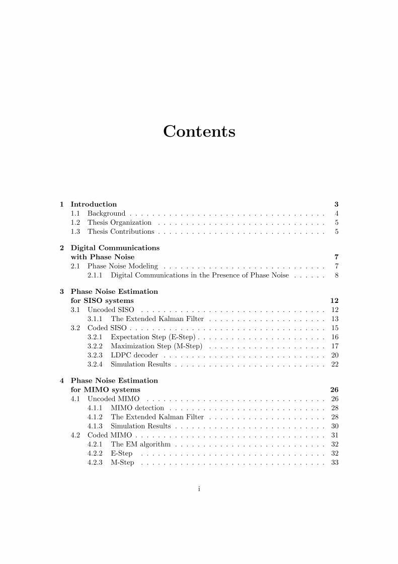
and zm(φ(k)),m = 1,2, . . . ,Nr, denotes the mth element of vector z(φ(k)). Note thatwe assume that H is known, s(k) is provided by the detector and zm(φ(k)) is a nonlinearfunction of φ(k).
It is assumed that perfect phase synchronization is obtained at the beginning of aframe by transmitting sufficient number of pilots. Then, the EKF is initialized with thestate estimate φ(0) = 0 and the error covariance estimate M(0) = σ2
∆I. The EKF first
estimates the a priori state vector φ−
(k), and the (Nr +Nt− 1)× (Nr +Nt− 1) a priorierror covariance matrix M
−(k) as follows
φ−
(k) = φ(k − 1) (4.12)
M−
(k) = M(k) + 2σ2∆I. (4.13)
Next, the EKF linearizes the nonlinear function z(φ(k)) in (4.11) about the a prioriestimate of the state vector using a first-order Taylor approximation as
z(φ(k)) ≈ z(φ−
(k)) + Z(k)(φ(k)− φ−
(k)) (4.14)
29

4.1. UNCODED MIMOCHAPTER 4. PHASE NOISE ESTIMATION
FOR MIMO SYSTEMS
where the Nr × (Nr + Nt − 1) Jacobian matrix with respect to φ at time instance k,Z(k), is defined as
Z(k) ,∂z
∂φ(k)
∣∣∣φ−
(k). (4.15)
The Jacobian matrix can be constructed with two matrices as
Z(k) = [Z1(k), Z2(k)] (4.16)
where the Nr ×Nr matrix Z1(k) is defined as
Z1(k) , diagjz1(φ
−(k)), . . . ,jzNr(φ
−(k))
(4.17)
and the Nr × (Nt − 1) matrix Z2(k) is given by
Z2(k),
jh11e
jφ−1 (k)s1(k)ejφ
−Nr+1(k) . . . jh1(Nt−1)e
jφ−1 (k)sNt−1(k)e
jφ−Nr+Nt−1(k)
jh21ejφ−2 (k)s1(k)ejφ
−Nr+1(k) . . . jh2(Nt−1)e
jφ−2 (k)sNt−1(k)e
jφ−Nr+Nt−1(k)
.... . .
...
jhNr1ejφ−Nr
(k)s1(k)ejφ−Nr+1(k) . . . jhNr(Nt−1)e
jφ−Nr
(k)sNt−1(k)ejφ−Nr+Nt−1(k)
.(4.18)
After the observation, the a posteriori estimate of the state vector, φ(k), and theerror covariance matrix, M(k), are given by
φ(k) = φ−
(k) + <K(k)(y(k)− z(φ−
(k))) (4.19)
M(k) =(I−<K(k)Z(k)
)M−
(k), (4.20)
where the (Nr +Nt − 1)×Nr Kalman Gain matrix, K(k), is given by
K(k) = M−
(k)Z(k)H(Cw + Z(k)M
−(k)Z(k)H
)−1. (4.21)
Finally, the observation noise covariance matrix is given by
Cw =(σ2
w
2+ j
σ2w
2
)I. (4.22)
4.1.3 Simulation Results
BER vs. Eb/N0 for BPSK modulation and ML equalization for a 2x2 MIMO systemwhere Lf = 1000 is shown in Fig. 4.1. It is seen that the EKF performs close to
the synchronized system at low to medium Eb/N0 levels where σ2∆ = 10
−3. On the
other hand, the BER performance of the system degrades at high Eb/N0 levels. Notethat the number of parameters to be tracked by the EKF is larger than the number ofobservation equations. This results in an error floor, i.e. the performance of the systemcannot be improved with increasing Eb/N0. The error floor depends on the phase noiseinnovation variance, σ2
∆. In Fig. 4.1 we observe that error floor tends to occur at lower
signal-to-ratios for the system with σ2∆ = 10
−2.
30

4.2. CODED MIMOCHAPTER 4. PHASE NOISE ESTIMATION
FOR MIMO SYSTEMS
Figure 4.1: BER vs. Eb/N0 for 2x2 uncoded MIMO system with BPSK modulation forvarious σ2
∆ values.
4.2 Coded MIMO
MIMO systems can utilize the available spectrum more efficiently [17],[18]. A numberof coding structures have been proposed in order to achieve high spectral efficiency,including multi-dimensional trellis-coded modulation [34], space time block codes [35],MIMO multilevel coding [36]. BICM is also one of the popular scheme that enablescommunication systems to fully exploit the spectrum efficiently [19, 20, 37].
Code-aided synchronization based on the EM framework for joint channel estima-tion, frequency and time synchronization for a BICM-MIMO system is proposed in [21].However, in [21], the synchronization parameters are assumed to be constant and de-terministic over the length of a block, which is not a valid assumption for time varyingphase noise. In the following, we show analytically how an EM-based algorithm with asoft decision-directed EKFS can be used to estimate and compensate time varying phasenoise.
First, we recall the signal model for uncoded MIMO systems. The received signal attime instance k is given by,
y(k) = Γ[r](k)HΓ[t](k)s(k) + w(k)
= X(k)s(k) + w(k)
31

4.2. CODED MIMOCHAPTER 4. PHASE NOISE ESTIMATION
FOR MIMO SYSTEMS
and the new state vector of length Nt +Nr − 1 can be written as
φ(k) = φ(k − 1) + ∆(k).
4.2.1 The EM algorithm
The EM algorithm iteratively solves an estimation problem where the observation,[Y]Nr×Lf
, [y(1),y(2), . . . ,y(Lf )], depends not only on the parameters to be esti-
mated, [Θ](Nr+Nt)×Lf, [θ(1),θ(2), . . . ,θ(Lf )], but also on some unknown parameters,
[S]Nt×Lf, [s(1), s(2), . . . ,s(Lf )] [15].
Given the observation sequence Y, the MAP estimate of Θ is given by [25]
Θ = arg maxΘ
ln p(Y|Θ) + ln p(Θ) (4.23)
where p(Y|Θ) =∑S
p(S)p(Y|S,Θ).
The EM algorithm consists of the expectation step (E-step) and maximization step(M-step) [16]. For the ith EM iteration, the E-step and M-step equations are given by
Q(Θ|Θ(i−1)
), E
S|Y,Θ(i−1)
ln p(Y|S,Θ)
+ ln p(Θ), (4.24)
Θ(i)
= arg maxΘ
Q(Θ|Θ(i−1)
), (4.25)
respectively. The EM algorithm converges to the MAP solution if the initial estimates ofthe parameters of interest, b(0), are sufficiently close to the true values of the parameters.Otherwise, the EM algorithm may converge to a saddle point or a local maximum. Toensure the convergence, pilot symbols are inserted into the data stream every pr timeinstances.
In the following subsections we derive the E-step and M-step of the EM algorithmfor coded MIMO systems.
4.2.2 E-Step
Let us define X(k) , Γ[r](k)HΓ[t](k). Consequently, the vector of received signals at thereceive antennas at time k, y(k) can be rewritten as
y(k) =X(k)s(k) + w(k). (4.26)
32

4.2. CODED MIMOCHAPTER 4. PHASE NOISE ESTIMATION
FOR MIMO SYSTEMS
According to (4.26), the LLF of the received signal matrix, Y, given the transmitteddata, S, and the phase noise process, Θ, is given by
ln p(Y|S,Θ) ∝−Lf∑k=1
‖ y(k)−X(k)s(k) ‖
∝2<Lf∑k=1
tr(y(k)sH(k)XH(k)
)
−Lf∑k=1
tr(X(k)s(k)sH(k)XH(k)
). (4.27)
Using (4.27) in (4.24) the E-step of the EM algorithm can be determined as
Q(Θ|Θ(i−1)
)=2<
Lf∑k=1
tr(y(k)αH(k)XH(k)
)
−Lf∑k=1
tr(X(k)B(k)XH(k)
)+ ln p(Θ), (4.28)
where
• α(k),Ess(k) =∑
an∈ΩNt
anp(s(k) = an|Y,Θ(i−1)
) and
• B(k),Ess(k)sH(k) =∑
an∈ΩNt
anaHn p(s(k) =an|Y,Θ
(i−1)).
In (4.28), α(k) denotes the marginal posterior mean of the coded symbol vector at time
instance k, p(s(k) = an|Y,Θ(i−1)
) denotes the APPs of the coded symbol vector given
Y and Θ(i−1)
, and B(k) is an (Nt ×Nt) matrix. As a result, the E-step reduces to thecomputation of the APPs. Note that the APPs can be computed via an iterative MAPdecoder which is outlined in Section 4.2.5.
4.2.3 M-Step
As shown in (4.25), the M-step maximizes the E-step with respect to the parameter ofinterest, Θ. In the following, it is shown that a low complexity soft decision-directedEKFS can be used to carry out the M-step of the EM algorithm.
Note that a Kalman filter is equivalent to a MAP estimator [25]. As a result, theKalman filter estimates of Θ, Θ can be written as
Θ =arg,maxΘln p(Y|Θ,S = A) + ln p(Θ) (4.29)
where A , [α(1),α(2), . . . ,α(Lf )] is an Nt × Lf matrix.
33

4.2. CODED MIMOCHAPTER 4. PHASE NOISE ESTIMATION
FOR MIMO SYSTEMS
By setting S = A, (4.27) can be rewritten as
ln p(Y|S = A,Θ) ∝2<Lf∑k=1
tr(y(k)αH(k)XH(k)
)
−Lf∑k=1
tr(X(k)α(k)αH(k)XH(k)
)+ ln p(Θ). (4.30)
Note that (4.30) and the E-step equation in (4.28) are equivalent to one another except
for the term
Lf∑k=1
tr(X(k)α(k)αH(k)XH(k)
). However, when the soft decisions reach
their true values, we can assume that α(k)αH(k) ≈ B(k). Thus, using (4.29) and(4.30), we can conclude that a Kalman filter can be applied to carry out the M-step ofthe EM algorithm.
Note that the observation equation for the Kalman filter is given by (4.26) whilebased on (4.2), the state equation at time k is given by
θ(k) =θ(k − 1) + ∆(k), (4.31)
where ∆(k) ,[∆
[r]1 (k), . . . ,∆
[r]Nr
(k),∆[t]1 (k), . . . ,∆
[t]Nt
(k)]T
. The transmitted symbols
s(k), can be replaced by their a posteriori means, i.e., soft decisions α(k) computedat the E-step using the iterative MAP detector in Section 4.2.5. Subsequently, theobservation equation in (4.26) can be rewritten as
y(k) ≈ X(k)α(k) + w(k). (4.32)
Since the observations are a nonlinear function of the parameters of interest, θk, anextended Kalman filter-smoother needs to be used instead to carry out the M-step of theEM algorithm [25].
4.2.4 The Extended Kalman Filter-Smoother
Note that (4.8) and (4.32) are similar. We can rewrite the observation equation for thecoded MIMO system as
y(k) = zc(φ(k)) + w(k). (4.33)
The EKFS first filters the received signal and provides phase noise estimates with aforward recursion over the frame. The filtering equations compute the posteriori estimate
of the state vector, φ+
(k), and the error covariance matrix, M+
(k), k = 2,3, . . . ,Lf in arecursive fashion according to (4.12-4.20) where z(φ(k)) is replaced by zc(φ(k)). In otherwords, instead of the hard decision vector provided by the ML detector in the uncodedMIMO system, s(k), the soft decision vector computed by the iterative detector, α(k),
34

4.2. CODED MIMOCHAPTER 4. PHASE NOISE ESTIMATION
FOR MIMO SYSTEMS
Equalizer
Iterative DetectorEstimator
Demapper Deinterleaver
Interleaver LDPC Decoder SlicerSymbol
Mapper
Extended Kalman Filter -
Smoother
Posterior Mapper
Soft Modem
Input (Received Signal)
Output
(Data bits)
Interleaver
Figure 4.2: Block diagram of the receiver structure.
is provided to the EKFS for the coded MIMO system. The EKFS is initialized with thestate estimate φ(0) = 0 and the error covariance estimate M(0) = σ2
∆I.After filtering is completed for the whole block, a backward recursion is performed
to smooth the estimates. Finally, the smoothed estimates of the phase noise parametersare carried out to be fed to the detector. The smoothed estimate of the phase noisevector, φ(k), and the error covariance matrix M(k) are given by
φ(k) = φ+
(k)+ M+
(k)(M−
(k))−1(φ(k + 1)−φ+
(k))
(4.34)
M(k) = M+
(k)+ M+
(k)(M−
(k))−1(M(k + 1)− M
+(k))
×(M
+(k)(M
−(k))−1
)T. (4.35)
After the backward recursion is completed the block of phase noise estimates φ(k),k =1,2, . . . ,Lf , is fed to the iterative detector for the next EM algorithm iteration.
4.2.5 Iterative Detector
It is shown in Sec. 4.2.3 that soft decisions, i.e., the marginal posterior probabilitiesof the coded symbol vectors A are required for the EKFS. The computation of thetrue posterior probabilities has a complexity that increases exponentially with the framelength Lf . Therefore, a near optimal iterative detector, operating according to theturbo principle [19],[20],[21] is used to obtain the marginal a posteriori bit probabilitiesgiven the phase noise estimates and the channel gain matrix H. Then, a soft modulatormaps the a posteriori bit probabilities to symbol probabilities and constructs the softdecisions. The block diagram of the proposed EM-based receiver structure, includingboth the EKFS and the iterative detector, is shown in Fig. 4.2.
The iterative detector first computes MNt conditional likelihoods of the symbol vec-
35

4.2. CODED MIMOCHAPTER 4. PHASE NOISE ESTIMATION
FOR MIMO SYSTEMS
tors given the phase noise estimates as
p(Y|s(k),Θ
(i−1))
= p(y(k)|s(k),Θ
(i−1))
= C ′exp(− 1
2σ2w
|y(k)−X(k)s(k)|2). (4.36)
Note that the conditional likelihoods are computed by the equalizer from the received sig-nal before the execution of the detector iterations. Iterative detection is then performedwith 3 nested iterations, as seen in Fig. 4.2.
The iterative part of the detector operates according to the turbo principle. Theconditional a posteriori probability of the transmitted symbol at the transmit antennam, at time instance k, sm(k), is factored as the product of an a priori probability (withsubscript a), and an extrinsic probability (with subscript e) such as
p(sm(k)|Y, Θ
(i−1))
= C(1)pa(sm(k))pe(sm(k)) (4.37)
where C(1) is a normalization constant. Note that since an interleaver at the transmitterside is used, the transmitted symbols on each antenna and the transmitted bits withineach constellation symbol are independent. The extrinsic symbol probabilities in (4.37)are computed by the equalizer in Fig. 4.2. The extrinsic symbol probability given theestimated phase noise parameters and the received signal pe(sm(k) = an) for an ∈ Ω, n =1,2, . . . ,M , is given by
pe(sm(k) = an) = p(Y|sm(k) = an,Θ
(i−1))
=∑
s(k):sm(k)=an
p(Y|s(k),Θ
(i−1))
×∏m′ 6=m
pa(sm′(k)). (4.38)
The a priori symbol probabilities pa(sm(k,d)) are computed by the soft modem and fedto the equalizer after decoding is performed. Therefore, the first iteration is betweenthe equalizer and the soft modem and there are Leq−sm iterations. The soft modemconsists of the demapper, the interleaver, the iterative MAP decoder, the deinterleaverand the mapper as it is shown in Fig. 4.2. The demapper takes the extrinsic symbolprobabilities from the equalizer and computes the extrinsic bit probabilities. The bitposterior probabilities of the dth bit of the bit sequence mapped to the symbol sm(k),denoted as sm(k,d), is factored similar to (4.37) as
p(sm(k,d)|Y,Θ(i−1)
)=C(2)pa(sm(k,d))pe(sm(k,d)). (4.39)
where C(2) is a normalization constant. Then, the extrinsic bit probability for β ∈ 0,1
36

4.2. CODED MIMOCHAPTER 4. PHASE NOISE ESTIMATION
FOR MIMO SYSTEMS
is computed by the demapper as
pe(sm(k,d) = β) = p(Y|sm(k,d) = β,Θ
(i−1))
=∑
an∈Ω:an(d)=β
pe(sm(k) = an)
∏d′ 6=d
pa(sm(k,d′)). (4.40)
The demapper also needs the a priori bit probabilities computed by the MAP decoder.The second iteration of the 3 nested iterations of the detector is performed between thedemapper and the decoder Ldm−dc times. After the demapper computes all the extrinsicbit probabilities, they are deinterleaved and provided to the MAP decoder by the deinter-leaver. The decoder takes the deinterleaved extrinsic bit probabilities and computes boththe deinterleaved posterior and the deinterlaved a priori bit probabilities exploiting code
properties with Ldec iterations. The posterior bit probabilities p(sm(k,d)|Y,Θ
(i−1))
are
sent out of the detector, interleaved and used to construct soft decisions for the EKFS,described in Section 4.2.4. The posterior bit probabilities are also used for hard decisionafter the algorithm terminates. The a priori bit probabilities pa(sn(k,d)) are sent tothe interleaver which constructs the a priori bit probabilities that are used as a prioriinformation by the demapper. Finally, the mapper converts a priori bit probabilitiesto a priori symbol probabilities which are used as a priori information by the equalizeraccording to
pa(sm(k,d)) =∏d
pa(sn(k,d)). (4.41)
Aforementioned, the iterative detector provides the EKFS with the marginal poste-
rior probabilities of the coded symbol vectors, p(s(k)|Y,Θ(i−1)
). The E-step is finished
by the computation of these probabilities as
p(s(k)|Y,Θ(i−1)
)=C(3)pa(s(k))pe(s(k)) (4.42)
=C(4)p(Y|s(k),Θ
(i−1))∏m,d
pa(sm(k,d)) (4.43)
where C(3) and C(4) are normalization constants. Then, these posterior probabilities areused to construct the soft decision, α(k).
The a priori symbol probabilities pa(sm(k)) and bit probabilities pa(sm(k,d)) areinitialized with a uniform distribution at the first EM algorithm iteration. A sufficientnumber of iterations inside of the detector is required for convergence if the detectoris reinitialized with uniform probabilities at each EM iteration. Instead, the detectorcan be initialized with the a priori probabilities obtained at the previous EM iteration.In addition, only 1 iteration is allowed inside of the iterative detector for each nested
37

4.2. CODED MIMOCHAPTER 4. PHASE NOISE ESTIMATION
FOR MIMO SYSTEMS
Figure 4.3: BER performance of the EM-based algorithm with DA(14) estimator.
iteration, i.e., Leq−dm = Ldm−dc = Ldec = 1 as suggested in [21]. This alternativeapproach requires more EM iterations but less detector iterations to converge. In thisway, the computational complexity of both the detector and the receiver can be reducedsignificantly.
4.2.6 Simulation Results
At the transmitter, data bits are first encoded by a rate R = 7/8 regular LDPC encoderfrom the NASA Goddard technical standard [26]. It is a regular code with variablenode degree 4 and check node degree 32. The number of data bits in each frame, Lbis equal to 7154. Then, encoded bits are modulated onto 16-QAM symbols. Therefore,there are Lf = Lb/NtR log2(M) = 1022 symbol vectors in each frame. Performancewill be measured as a function of Eb/N0, where Eb denotes the transmitted energy perinformation bit and N0 is the power spectral density of the AWGN, i.e, σ2
w = N0.The convergence of the EM based estimator is severely dependent on the initialization
of the estimation parameters. First, the EM based algorithm is initialized by a data aided(DA) estimator to provide the initial phase noise estimates. Pilots are inserted into thedata stream every pr time instance. At the first EM algorithm iteration, the EKFS makesuse of the pilots and estimates phase noise values at each pr time instance. Afterwardsa linear interpolation is performed between two consecutive phase noise estimates. Asa result, initial phase noise estimates are obtained and sent to the iterative detector toinitialize the EM-based algorithm. DA(pr) denotes the DA estimator with pilot rate pr.
In Fig. 4.3, the effect of the phase noise on the BER performance correspondingto the EM-based algorithm with DA(14) estimator for different phase noise innovation
38
4.2. CODED MIMOCHAPTER 4. PHASE NOISE ESTIMATION
FOR MIMO SYSTEMS
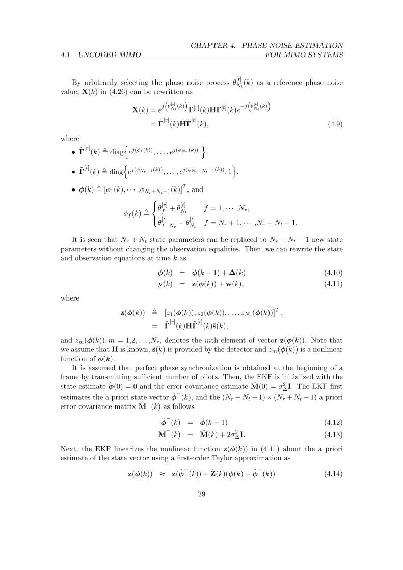
Figure 4.4: FER performance of the EM-based algorithm at several iterations where σ2∆ =
5 · 10−5, and DA initial estimation with pr = 14.
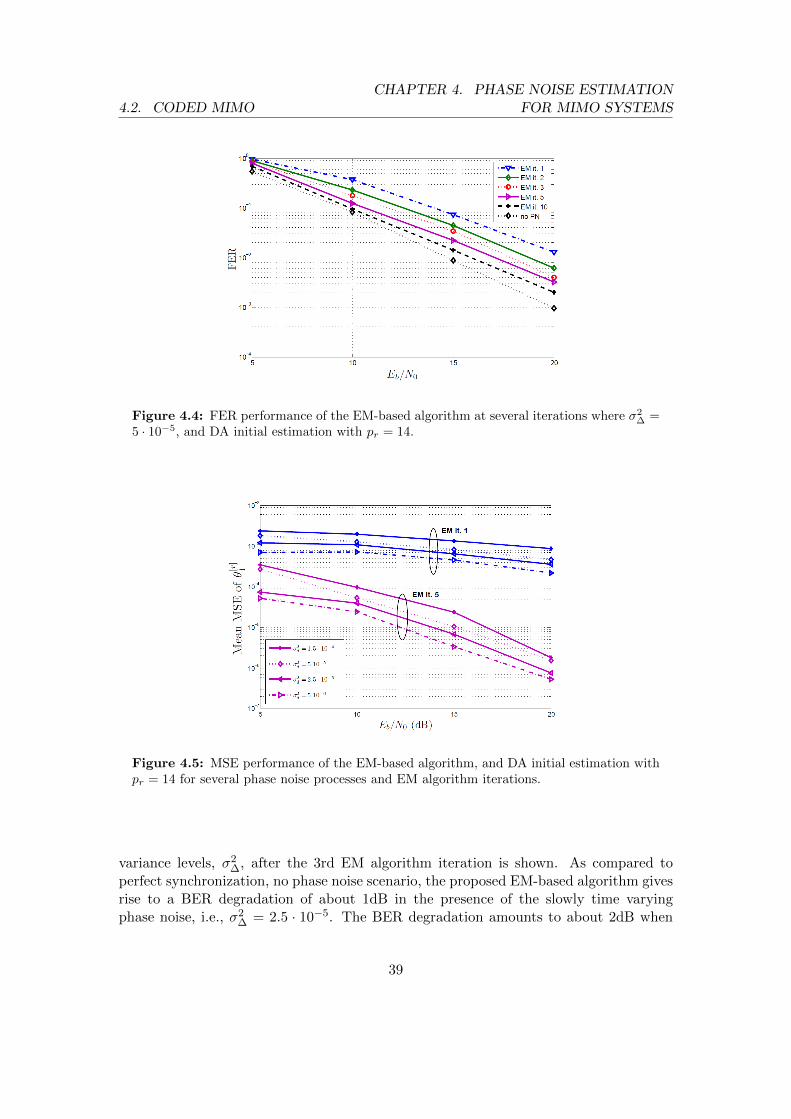
Figure 4.5: MSE performance of the EM-based algorithm, and DA initial estimation withpr = 14 for several phase noise processes and EM algorithm iterations.
variance levels, σ2∆, after the 3rd EM algorithm iteration is shown. As compared to
perfect synchronization, no phase noise scenario, the proposed EM-based algorithm givesrise to a BER degradation of about 1dB in the presence of the slowly time varyingphase noise, i.e., σ2
∆ = 2.5 · 10−5. The BER degradation amounts to about 2dB when
39

4.2. CODED MIMOCHAPTER 4. PHASE NOISE ESTIMATION
FOR MIMO SYSTEMS
Figure 4.6: FER performance of the EM-based algorithm, and DA initial estimation withpr = 14 for several number of decoder iterations, σ2
∆ = 5 · 10−4.
σ2∆ = 1.5 · 10−4. It is possible to track a stronger phase noise process with innovation
variance σ2∆ = 2.5 ·10−4 in expense of 4dB of Eb/N0 comparing to perfectly synchronized
system. Note that the performance of the system tends to stay constant as Eb/N0
increases, yielding an error floor. The main reason is that the prediction error of theEKFS is determined by the phase noise innovation variance. As σ2
∆ increases, the errorfloor is observed at higher error rates.
Code-aided synchronization techniques offer to improve the overall accuracy andperformance of the system. First, we investigate the performance of the EM-basedalgorithm at each EM algorithm iteration. The EM-based algorithm does not convergeto the global solution at some of the erroneous frames resulting in an arbitrary largenumber of erroneous bits. For this reason the BER performance of the system may notincrease at each EM algorithm iteration. Therefore, the FER performance of the systemis investigated. Fig. 4.4 shows the FER performance at several EM algorithm iterationsfor σ2
∆ = 5 · 10−5. We observe that the FER performance of the system improves ateach EM algorithm iteration. In order to operate the system at 2 · 10−3 FER at the10th iteration, additional Eb/N0 of about 2dB is required. Secondly, we investigate theestimation accuracy of the EM-based algorithm. The MSE of the phase noise estimatesat the first receive antenna is averaged over the successfully decoded frames. Fig. 4.5shows the MSE results of different levels of phase noise innovation variance at both the1st and the 5th EM algorithm iteration. It is seen that the proposed EM-based algorithmnot only increases the overall performance of the system but also yields better estimatesat each EM algorithm iteration.
We also investigate the performance of the proposed EM-based algorithm for thesystem that is affected by a severe phase noise process such that σ2
∆ = 5 · 10−4. Fig.
40

4.2. CODED MIMOCHAPTER 4. PHASE NOISE ESTIMATION
FOR MIMO SYSTEMS
Figure 4.7: FER performance of the EM-based algorithm at several iterations where σ2∆ =
5 · 10−4, DA initial estimation with pr = 14, and R = 1/2 rate code.
4.6 shows the effect of the number of decoder iterations on the FER performance of thesystem for a fixed Eb/N0 = 20dB. We observe that the performance of the system doesnot improve significantly after a few EM algorithm iterations. In contrast, the FERperformance of the system can be slightly improved with more iterations inside of thedecoder. In order to achieve lower error rates in the presence of strong phase noise astronger channel encoder can be used, i.e, the rate of the LDPC code, R, needs to bedecreased. Note that the spectral efficiency of the system also reduces with decreasingR yielding low throughput.
Fig 4.7 shows the FER performance of the EM-based algorithm for σ2∆ = 5 · 10−4
where data bits are encoded by a rate R = 1/2 LDPC encoder [38]. We observe thatthe FER performance can be improved significantly by increasing the number of EMiteration. It is possible to achieve 5 · 10−3 FER in expense of 4dB of Eb/N0 comparingto no phase noise scenario. However, the error floor still occurs. It is concluded that thenumber of the decoder iterations of the EM-based algorithm, Ldec, should be tuned to asufficiently large number to be able to track time varying phase noise.
41

5Conclusion and Future Work
5.1 Conclusion
In this thesis, phase noise estimation in uncoded/coded SISO and MIMO system isanalyzed.
In Chapter 3, phase noise tracking is performed by a hard decision directed EKFfor the uncoded SISO system. Numerical results shows that the EKF is able to trackslowly time varying phase noise processes. Unsurprisingly, the BER degradation reacheslarge values when the phase noise innovation variance is high. Additionally, in Chapter3, the problem of joint phase noise estimation and detection in a coded SISO systemwith LDPC codes is discussed. The EM-based algorithm proposed in [8] is modified andanalytically derived. Two estimators, a soft decision directed KS-MLA and a soft deci-sion directed EKS proposed in [8] are applied to carry out the maximization step of theEM-based algorithm. In [8], the KS-MLA is claimed to have superior performance thanthe EKS. However, numerical results in Chapter 3 indicates that when phase noise overthe frame reaches very large values, i.e., in the case of large block length and/or phasenoise innovation variance, the performance of the KS-MLA degrades significantly andthe EKS performs better than the KS-MLA. The KS-MLA removes the data dependencyby multiplying the observed signal with the soft decision symbol. As a result, the per-formance of the KS-MLA degrades faster than the EKS when the soft decisions are lessreliable. For instance, for the same phase noise innovation variance, the EKFS performsbetter than the KS-MLA when the constellation density increases. A trick to increase thealgorithm speed is also discussed and shown to decrease the overall complexity requiredfor convergence.
In Chapter 4, a low complexity hard decision directed EKF is derived and applied toan uncoded MIMO system. Simulation results show that the EKF performs close to thesynchronized system in the case of slowly time varying phase noise process. The problemof joint estimation of the time varying phase noise and data detection for a LOS-MIMO
42

5.2. FUTURE WORK CHAPTER 5. CONCLUSION AND FUTURE WORK
system using bit interleaved coded modulation and LDPC codes is also discussed. Aniterative EM-based receiver to perform code-aided synchronization is proposed. A newlow complexity soft-decision directed EKFS is derived and embedded into the EM-basedalgorithm. The performance of the system is investigated in terms of the BER and theFER. Estimation accuracy of the phase noise parameters is presented with average MSEcurves. Computational complexity of the system is also discussed. Computer simulationsshow that the number of bit errors does not decrease at each EM algorithm iteration if thealgorithm fails to converge. Instead, the FER performance is shown to decrease at eachEM iteration. Simulation results demonstrate that the proposed EM-based algorithmestimates and compensates the time varying phase noise with a small degradation ofthe performance for a wide range of phase noise innovation variances. However, anerror floor occurs at high signal-to-noise ratio levels. To reduce the error floor and totrack the phase noise process with large innovation variance decoding performance canbe increased by setting the number of decoder iterations to larger values. However, theachieved performance gain is not significant comparing to the introduced complexity. Onthe other hand, coding rate can be reduced further to protect data bits, yielding bettersoft decisions. The FER performance can be significantly improved by utilizing low rateLDPC codes at the expense of a decrease in throughput. As a result, the EKFS canbe applied to a coded LOS-MIMO system for the wide range of phase noise innovationvariances. The system parameters should be set to achieve the target performance.
5.2 Future Work
In Chapter 4, the channel gains are assumed to be known at the receiver side. Theeffects of the estimation errors of the channel gains on the performance of the EM-basedalgorithm is not investigated. The channel gains can be obtained by a conventional data-aided estimator. Additionally, the channel estimation of the block fading MIMO systemscan be embedded into the EM-based algorithms and initial estimates can be improvedat every EM algorithm iteration. Therefore, this work can be extended to joint phasenoise and channel estimation and data detection. In [27], a data-aided LS estimator adecision-directed WLS estimator and a new decision-directed EKF is proposed. Theseestimators can be used in the EM-based algorithm to carry out the maximization step.Finally, statistics of the phase noise estimates can be used by taking into account in thedecoding process. A receiver employing factor graphs can be implemented and to trackstrong phase noise processes.
43

Bibliography
[1] E. Boch, “High-capacity ethernet backhaul radio systems for advanced mobile datanetworks [application notes],” IEEE Microw. Mag., vol. 10, no. 5, pp. 108–114, Aug.2009.
[2] F. Bøhagen, P. Orten, and G. E. Øien, “Design of capacity-optimal high-rank line-of-sight MIMO channels,” IEEE Trans. Wireless Commun., vol. 4, no. 6, pp. 790–804, Apr. 2007.
[3] A. Demir, A. Mehrotra, and J. Roychowdhury,“Phase noise in oscillators: a unifyingtheory and numerical methods for characterization,” IEEE Trans. Circuits Syst. I,Fundam. Theory Appl., vol. 47, no. 5, pp. 655–674, May 2000.
[4] H. Meyr, M. Moeneclaey, and S. Fechtel, Digital Communication Receivers: Syn-chronization, Channel Estimation, and Signal Processing. New York, NY, USA:John Wiley & Sons, Inc., 1997.
[5] G. Colavolpe, A. Barbieri, and G. Caire, “Algorithms for iterative decoding in thepresence of strong phase noise,” IEEE J. Sel. Areas Commun., vol. 23, no. 9, pp.1748 – 1757, Sep. 2005.
[6] S. Godtmann, N. Hadaschik, A. Pollok, G. Ascheid, and H. Meyr, “Iterative code-aided phase noise synchronization based on the lmmse criterion,” in IEEE Workshopon Signal Process. Advances in Wireless Commun., June 2007, pp. 1 –5.
[7] V. Simon, A. Senst, M. Speth, and H. Meyr, “Phase noise estimation via adaptedinterpolation,” in IEEE Global Commun. Conf., vol. 6, 2001, pp. 3297–3301.
[8] T. Shehata and M. El-Tanany, “Joint iterative detection and phase noise estimationalgorithms using kalman filtering,” in Proc. Canadian Workshop on Inf. Theory,May 2009, pp. 165–168.
[9] J. Bhatti and M. Moeneclaey, “Performance analysis of iterative decision-directedphase noise estimation,” in Future Network and Mobile Summit, Jun. 2010, pp. 1–8.
44

BIBLIOGRAPHY BIBLIOGRAPHY
[10] Y. Wang and D. Falconer, “Phase noise estimation and suppression for single carrierSDMA uplink,” Proc. IEEE Wireless Commun. and Networking Conf., Jul. 2010.
[11] C. Berrou, A. Glavieux, and P. Thitimajshima,“Near Shannon limit error-correctingcoding and decoding: Turbo-codes,” in IEEE Proc. on Int. Conf. on Commun.,vol. 2, May 1993.
[12] R. Gallager, “Low-density parity-check codes,” IRE Trans. Inf. Theory, vol. 8, no. 1,pp. 21–28, Jan. 1962.
[13] V. Lottici and M. Luise, “Embedding carrier phase recovery into iterative decodingof turbo-coded linear modulations,” IEEE Trans. Commun., vol. 52, no. 4, pp.661–669, Apr. 2004.
[14] N. Noels et. al , “A theoretical framework for soft-information-based synchroniza-tion in iterative (turbo) receivers,” EURASIP Wireless Communication Networks,no. 2, pp. 117–129, 2005.
[15] T. Moon, “The expectation-maximization algorithm,” IEEE Workshop on Multime-dia Signal Process., vol. 13, no. 6, pp. 47–60, Nov. 1996.
[16] C. Herzet, N. Noels, V. Lottici, H. Wymeersch, M. Luise, M. Moeneclaey, andL. Vandendorpe, “Code-aided turbo synchronization,” Proc. IEEE, vol. 95, no. 6,pp. 1255 –1271, Jun. 2007.
[17] I. E. Telatar, “Capacity of multi-antenna Gaussian channels,” European Transac-tions on Telecommunications, vol. 10, pp. 585–595, 1999.
[18] G. J. Foschini and M. J. Gans, “On limits of wireless communications in a fadingenvironment when using multiple antennas,” Wireless Personal Communications,vol. 6, pp. 311–335, 1998.
[19] A. Stefanov and T. Duman, “Turbo-coded modulation for systems with transmitand receive antenna diversity over block fading channels: system model, decodingapproaches, and practical considerations,” IEEE J. Sel. Areas Commun., vol. 19,no. 5, pp. 958–968, May 2001.
[20] J. Boutros, F. Boixadera, and C. Lamy, “Bit-interleaved coded modulations formultiple-input multiple-output channels,” in Proc. IEEE Int. Symposium on SpreadSpectrum Techniques and Applications, vol. 1, Sep. 2000, pp. 123–126.
[21] F. Simoens, H. Wymeersch, H. Steendam, and M. Moeneclaey, Synchronization forMIMO systems. Hindawi Publishing, 2005.
[22] N. Hadaschik, M. Dorpinghaus, A. Senst, O. Harmjanz, U. Kaufer, G. Ascheid, andH. Meyr, “Improving MIMO phase noise estimation by exploiting spatial correla-tions,” in Proc. IEEE Int. Conf. on Acoustics, Speech and Signal Process., Philadel-phia, 2005, pp. 833–836.
45

BIBLIOGRAPHY BIBLIOGRAPHY
[23] F. M. Gardner, Phaselock Techniques, 1966.
[24] E. Alpman, “Estimation of oscillator phase noise for mpsk-based communicationsytems over awgn channels,” Master’s thesis, Chalmers University of Technology,2004.
[25] S. M. Kay, Fundamentals of Statistical Signal Processing, Estimation Theory. Pren-tice Hall, Signal Processing Series, 1993.
[26] “Goddard technical standard: Low density parity check code for rate 7/8,” NASAGoddard Space Flight Center, Tech. Rep. GSFC-STD-9100.
[27] H. Mehrpouyan, A. A. Nasir, S. D. Blostein, T. Eriksson, G. Karagiannidis, andT. Svensson, “Joint estimation of channel and oscillator phase noise in mimo sys-tems,” IEEE Trans. Signal Process., vol. 60, no. 9, pp. 4790–4807, Sep. 2012.
[28] G. Golden, C. Foschini, R. Valenzuela, and P. Wolniansky, “Detection algorithmand initial laboratory results using v-blast space-time communication architecture,”Electronics Letters, vol. 35, no. 1, pp. 14 –16, Jan. 1999.
[29] P. Wolniansky, G. Foschini, G. Golden, and R. Valenzuela, “V-blast: an architecturefor realizing very high data rates over the rich-scattering wireless channel,” in URSIInt. Symposium on Signals, Systems, and Electronics, Sep. 1998, pp. 295–300.
[30] E. Viterbo and J. Boutros, “A universal lattice code decoder for fading channels,”IEEE Trans. Inf. Theory, vol. 45, no. 5, pp. 1639 –1642, July 1999.
[31] L. G. Barbero and J. S. Thompson, “Fixing the complexity of the sphere decoderfor mimo detection,” IEEE Trans. Wireless Commun., pp. 2131–2142, 2008.
[32] E. Agrell, T. Eriksson, A. Vardy, and K. Zeger, “Closest point search in lattices,”IEEE Trans. Inf. Theory, vol. 48, no. 8, pp. 2201–2214, Aug. 2002.
[33] C. Windpassinger and R. Fischer, “Low-complexity near-maximum-likelihood de-tection and precoding for mimo systems using lattice reduction,” in Proc. IEEE Inf.Theory Workshop, Mar. 2003.
[34] V. Tarokh, A. Naguib, N. Seshadri, and A. Calderbank, “Space-time codes for highdata rate wireless communication: performance criteria in the presence of channelestimation errors, mobility, and multiple paths,” IEEE Trans. Commun., vol. 47,no. 2, pp. 199 –207, Feb. 1999.
[35] S. Alamouti, “A simple transmit diversity technique for wireless communications,”IEEE J. Sel. Areas Commun., vol. 16, no. 8, pp. 1451 –1458, Oct. 1998.
[36] L.-J. Lampe, R. Schober, and R. Fischer, “Multilevel coding for multiple-antennatransmission,” IEEE Transa. Wireless Commun., vol. 3, no. 1, pp. 203 – 208, Jan.2004.
46

BIBLIOGRAPHY BIBLIOGRAPHY
[37] M. Sellathurai and S. Haykin, “Turbo-blast: performance evaluation in correlatedrayleigh-fading environment,” IEEE J. Sel. Areas Commun., vol. 21, no. 3, pp. 340– 349, Apr. 2003.
[38] D. J. C. MacKay., “Regular LDPC online database. [online]. available:,” http://www.inference.phy.cam.ac.uk/mackay/, accessed: September 7, 2012.
47