pharma-slide - rytec...
TRANSCRIPT

Pharma-Slide
Owner’s Manual
®
[Revision: June 14, 2010, SL150000, ©Rytec Corporation 2005]

WARRANTY
The Pharma-Slide High-Speed Door purchased by you (Buyer) should not be installed or operated before you read all associated product manuals explaining the proper method of installing, operating, and maintaining the equipment.
Rytec Corporation (Seller) warrants that the Pharma-Slide High-Speed Door (Product) sold to the Buyer will be free of defects in materials and workmanship under normal use for a period of twelve (12) months from the date of shipment of the Product from the Seller’s plant. Electrical components are warranted for a period of ninety (90) days from the date of shipment. If within the applicable period any Products shall be proved to the Seller’s satisfaction to be defective, such Products shall be repaired or replaced at the Seller’s option. Such repair or replacement shall be the Seller’s sole obligation and the Buyer’s exclusive remedy hereunder and shall be conditioned upon the Seller receiving written notice of any alleged defect within ten (10) days after its discovery and, at the Seller’s option, return of such Product to the Seller, f.o.b. its factory. THIS WARRANTY IS EXCLUSIVE AND IN LIEU OF ALL OTHER REPRESENTATION AND WARRANTIES, EXPRESS OR IMPLIED, AND THE SELLER EXPRESSLY DISCLAIMS AND EXCLUDES ANY IMPLIED WARRANTY OF MERCHANTABILITY OR FITNESS FOR PURPOSE.
PARTS AND ASSEMBLIES sold separately by Rytec Corporation that fail due to defects in material or workmanship within ninety (90) days from the date of shipment will be replaced under warranty provided installation has been carried out in accordance with all Rytec procedures. This warranty is limited to providing a replacement part only. This warranty does not cover freight, special charges, or any costs associated with the installation of the replacement part.
Any description of the Product, whether in writing or made orally by the Seller or the Seller’s agents, specifications, samples, models, bulletins, drawings, diagrams, engineering or similar materials used in connection with the Buyer’s order, are for the sole purpose of identifying the Product and shall not be construed as an express warranty. Any suggestions by the Seller or the Seller’s agents regarding the use, application, or suitability of the Product shall not be construed as an express warranty unless confirmed to be such in writing by the Seller.
The Seller’s liability with respect to the Product sold to the Buyer shall be limited to the warranty provided herein. THE SELLER SHALL NOT BE SUBJECT TO ANY OTHER OBLIGATIONS OR LIABILITIES, WHETHER ARISING OUT OF BREACH OF CONTRACT, WARRANTY, TORT (INCLUDING NEGLIGENCE AND STRICT LIABILITY) OR OTHER THEORIES OF LAW, WITH RESPECT TO PRODUCTS SOLD OR SERVICES RENDERED BY THE SELLER, OR ANY UNDERTAKINGS, ACTS, OR OMISSIONS RELATING THERETO. Without limiting the generality of the foregoing, the Seller specifically disclaims any liability for property or personal injury damages, penalties, special or punitive damages, damages for lost profits or revenues, services, downtime, shutdown, or slowdown costs, or for any other types of economic loss, and for claims of the Buyer’s customers or any third party for any such damages. THE SELLER SHALL NOT BE LIABLE FOR AND DISCLAIMS ALL CONSEQUENTIAL, INCIDENTAL, AND CONTINGENT DAMAGES WHATSOEVER.
This warranty shall be void in its entirety if the failure of any product shall be caused by any installation, operation, or maintenance of the Product which does not conform with the requirements set forth by the Seller in the applicable product manuals or is the result of any cause other than a defect in the material or workmanship of the product.
10/11/06
TABLE OF CONTENTS
PAGE
INTRODUCTION. . . . . . . . . . . . . . . . . . . . . . . . . . . . . . . . . . . . . . . . . . . . .1
DOOR SERIAL NUMBER(S). . . . . . . . . . . . . . . . . . . . . . . . . . . . . . . . . . . . . . . . . . .1
HOW TO USE MANUAL . . . . . . . . . . . . . . . . . . . . . . . . . . . . . . . . . . . . . . . . . . . . . .1
GENERAL ARRANGEMENT OF DOOR PARTS . . . . . . . . . . . . . . . . . . . . . . . . . . .1
OPERATION . . . . . . . . . . . . . . . . . . . . . . . . . . . . . . . . . . . . . . . . . . . . . . . .1
AUTOMATIC DOOR SYSTEM. . . . . . . . . . . . . . . . . . . . . . . . . . . . . . . . . . . . . . . . . .1
PHOTO EYES . . . . . . . . . . . . . . . . . . . . . . . . . . . . . . . . . . . . . . . . . . . . . . . . . . . . . .2
MOVING THE DOOR MANUALLY . . . . . . . . . . . . . . . . . . . . . . . . . . . . . . . . . . . . . .2
PLANNED MAINTENANCE . . . . . . . . . . . . . . . . . . . . . . . . . . . . . . . . . . . .2
RECOMMENDED SCHEDULE . . . . . . . . . . . . . . . . . . . . . . . . . . . . . . . . . . . . . . . . .2
DAILY INSPECTION . . . . . . . . . . . . . . . . . . . . . . . . . . . . . . . . . . . . . . . . . . . . . . . . .3
Damage Inspection . . . . . . . . . . . . . . . . . . . . . . . . . . . . . . . . . . . . . . . . . . . . .3
Door Operation . . . . . . . . . . . . . . . . . . . . . . . . . . . . . . . . . . . . . . . . . . . . . . . .3
Photo Eye Inspection . . . . . . . . . . . . . . . . . . . . . . . . . . . . . . . . . . . . . . . . . . .3
QUARTERLY INSPECTION . . . . . . . . . . . . . . . . . . . . . . . . . . . . . . . . . . . . . . . . . . .3
Mounting Hardware Inspection . . . . . . . . . . . . . . . . . . . . . . . . . . . . . . . . . . .3
Door Limit Inspection . . . . . . . . . . . . . . . . . . . . . . . . . . . . . . . . . . . . . . . . . . .4
Activator Inspection . . . . . . . . . . . . . . . . . . . . . . . . . . . . . . . . . . . . . . . . . . . .4
Seal Inspection . . . . . . . . . . . . . . . . . . . . . . . . . . . . . . . . . . . . . . . . . . . . . . . .4
Control Panel Inspection . . . . . . . . . . . . . . . . . . . . . . . . . . . . . . . . . . . . . . . .4
Electrical Connection Inspection. . . . . . . . . . . . . . . . . . . . . . . . . . . . . . . . . .4
Wall Anchor Inspection. . . . . . . . . . . . . . . . . . . . . . . . . . . . . . . . . . . . . . . . . .4
ADJUSTMENTS . . . . . . . . . . . . . . . . . . . . . . . . . . . . . . . . . . . . . . . . . . . . .5
DOOR PANEL . . . . . . . . . . . . . . . . . . . . . . . . . . . . . . . . . . . . . . . . . . . . . . . . . . . . . .5
DOOR SEAL . . . . . . . . . . . . . . . . . . . . . . . . . . . . . . . . . . . . . . . . . . . . . . . . . . . . . . .6
SEAL STOP. . . . . . . . . . . . . . . . . . . . . . . . . . . . . . . . . . . . . . . . . . . . . . . . . . . . . . . .7
BELT TENSION (SINGLE AND BI-PARTING) . . . . . . . . . . . . . . . . . . . . . . . . . . . . .8
MISCELLANEOUS. . . . . . . . . . . . . . . . . . . . . . . . . . . . . . . . . . . . . . . . . . .8
PANEL CLEANING . . . . . . . . . . . . . . . . . . . . . . . . . . . . . . . . . . . . . . . . . . . . . . . . . .8

TORMAX OPERATOR . . . . . . . . . . . . . . . . . . . . . . . . . . . . . . . . . . . . . . . .9
TORMAX OPERATOR TERMINALS. . . . . . . . . . . . . . . . . . . . . . . . . . . . . . . . . . . . .9
TORMAX OUTPUT RELAYS. . . . . . . . . . . . . . . . . . . . . . . . . . . . . . . . . . . . . . . . . . .9
DIAGRAM . . . . . . . . . . . . . . . . . . . . . . . . . . . . . . . . . . . . . . . . . . . . . . . . . . . . . . . .10
PARTS LIST . . . . . . . . . . . . . . . . . . . . . . . . . . . . . . . . . . . . . . . . . . . . . . .11
PARTS ORDERING INFORMATION . . . . . . . . . . . . . . . . . . . . . . . . . . . . . . . . . . .11
How to Order Parts . . . . . . . . . . . . . . . . . . . . . . . . . . . . . . . . . . . . . . . . . . . .11
DOOR SERIAL NUMBER(S). . . . . . . . . . . . . . . . . . . . . . . . . . . . . . . . . . . . . . . . . .11
Substitute Parts . . . . . . . . . . . . . . . . . . . . . . . . . . . . . . . . . . . . . . . . . . . . . . .11
Return of Parts. . . . . . . . . . . . . . . . . . . . . . . . . . . . . . . . . . . . . . . . . . . . . . . .11
SINGLE SLIDE DOOR . . . . . . . . . . . . . . . . . . . . . . . . . . . . . . . . . . . . . . . . . . . . . .12
BI-PARTING DOOR . . . . . . . . . . . . . . . . . . . . . . . . . . . . . . . . . . . . . . . . . . . . . . . .14

INTRODUCTION—DOOR SERIAL NUMBER(S)
INTRODUCTIONThe information contained in this manual will allow you to operate and maintain your Rytec Pharma-Slide® Door in a manner which will ensure maximum life and trouble-free operation.
Any unauthorized changes in procedure, or failure to fol-low the steps as outlined in this manual, will automatically void the warranty. Any changes in the working parts, assemblies, or specifications as written that are not authorized by Rytec Corporation will also cancel the war-ranty. The responsibility for the successful operation and performance of this door lies with the owner of the door.
DO NOT OPERATE OR PERFORM MAINTENANCE ON THIS DOOR UNTIL YOU READ AND UNDERSTAND THE INSTRUCTIONS CONTAINED IN THIS MANUAL.
If you have any questions, contact your Rytec represen-tative or call the Rytec Customer Support Department at 1-800-628-1909. Always refer to the serial number of the door when calling the representative or Customer Sup-port.
The wiring connections in this manual are for general information purposes only. A wiring schematic is pro-vided with each individual door specifically covering the control panel and electrical components of that door. That schematic was shipped inside the control panel.
DOOR SERIAL NUMBER(S)
The DOOR SERIAL NUMBER is located on the left side of the head assembly, behind the hood.
IMPORTANT: When installing multiple doorsof the same model but in differ-ent sizes, verify serial number inthe head assembly.
HOW TO USE MANUAL
Throughout this manual, the following key words are used to alert the reader to potentially hazardous situa-tions, or situations where additional information to suc-cessfully perform the procedure is presented:
WARNING is used to indicate the potentialfor personal injury, if the procedure is notperformed as described.
CAUTION is used to indicate the potential fordamage to the product or property damage,if the procedure is not followed as described.
IMPORTANT: IMPORTANT is used to relayinformation CRITICAL to thesuccessful completion of theprocedure.
NOTE: NOTE is used to provide additional infor-mation to aid in the performance of theprocedure or operation of the door, but notnecessarily safety related.
GENERAL ARRANGEMENT OF DOOR PARTS
Figure 1 shows the location of the major components of the door and the general placement of the associated control sub-assemblies for a typical installation.
This illustration is provided to you for general informa-tion purposes only. It should not be relied upon solely for the operation and maintenance of your door and its sub-assemblies.
Figure 1
NOTE: Figure 1 shows the front of the door. Leftand right are determined when viewing thefront of the door.
OPERATION
AUTOMATIC DOOR SYSTEM
The Pharma-Slide door is equipped with an automatic Tormax® drive system, designed exclusively to operate Rytec high-performance doors. It provides connections for safety beams, door limit settings, and fault indication. For more information, see the Tormax Operating Instruction manual.
A3100224
End
HeadAssembly
Seal Stop Column
Column
Tormax Control Drive withHood Half Removed
Door Panel
with Wall Jamb
Serial Number Location
1

PLANNED MAINTENANCE—PHOTO EYES
PHOTO EYES
Your door is equipped with four photo eyes mounted on the front of the door. The purpose of these photo eyes is to hold the door open or, if the door is closing, reverse the door to the open position if a vehicle, person, or any object is in the path of the photo eye beam.
The photo eye is not active when the door is closed. After the obstruction breaking the photo eye beam is removed:
• The door will remain open if it was originally opened by a non-automatic activator until it is closed by a non-automatic activator.
• The door will close automatically if it was originally opened with an automatic activator.
NOTE: The photo eyes are not intended to beused as a door activator and will not openthe door when it is closed.
This safety system consists of two pairs of non-adjustable emitter and receiver modules. There are no alignment, gain, or sensitivity settings.
NOTE: When photo eyes are installed, theyshould be installed opposite of each otherto avoid any interference. See Figure 2 forclarification.
Figure 2
MOVING THE DOOR MANUALLY
Forcing the door open may cause personalinjury or equipment failure.
There are two ways of opening manually:
1. Turn off or disconnect power to the Tormax opera-tor.
2. Switch to operating mode P and the door panel(s) can be moved freely. To put the door back into oper-ation again, select the previous operating mode.
NOTE: Reference the Tormax manual for manualoperation and software reset.
PLANNED MAINTENANCE
RECOMMENDED SCHEDULE
The maintenance interval is determined by how fre-quently the system is used. However, checking and maintenance must be performed at least once a year by an authorized technician.
NOTE: Spare parts must comply with the techni-cal requirements of the manufacturer. Usegenuine spare parts exclusively.
The owner should maintain and provide amaintenance log for the technician. Inspec-tion results should be entered in the logwith the authorized technician’s signatureand date.
A5600026
Receiver
Transmitter
Transmitter
Receiver
Side Columns
Daily Quarterly
Damage Inspection X
Door Operation X
Photo Eye Inspection X
Mounting Hardware Inspection X
Door Limit Inspection X
Activator Inspection X
Seal Inspection X
Control Panel Inspection X
Electrical Connection Inspection X
Wall Anchor Inspection X
2

PLANNED MAINTENANCE—DAILY INSPECTION
DAILY INSPECTION
Damage Inspection
Visually inspect the door for damaged components. Examples:
Head Assembly: Inspect for dents or damage that may prevent the door from opening or closing properly.
Door Panel: Inspect for dents, holes, and worn areas. If equipped with window(s), inspect them for damage or dirt that may impair vision — clean or replace as required.
End Column and Seal Stop: Inspect for damage and wear that may prevent the door from holding a proper seal.
Drive Belt: Inspect for damage and wear that may pre-vent the door from operating properly.
Photo Eyes: Inspect the lens of each photo eye for damage or dirt that may prevent the photo eyes from working properly — clean or replace as required.
Door Operation
Run the door through four or five complete cycles to ensure the door is operating smoothly and efficiently and that binding or unusual noises do not exist. DO NOT continue to operate the door if it is not running properly, as this could cause additional damage.
DO NOT stand in the way of the door panelwhen performing the following inspection.
Photo Eye Inspection
NOTE: Four photo eyes have been provided withthe door. These photo eyes act as a safetydevice to prevent the door from closing ifan object is within the photo eye beam.The safety photo eyes are not meant to beused as door activators.
1. Activate the door to open.
NOTE: The door opens by a device such as a sen-sor, push button panel, or card reader.
2. Place an object in front of the photo eye in a position where it will break the photo eye beam. The photo eye will recognize a person or object while the door is open and the door will remain open. As the door is closing, a person or object passes through the photo eye beam and the door immediately reopens.
Personnel or objects being used for thisinspection should not be in the path of thedoor panel when this check is made. If aphoto eye is not working properly, the doorpanel will close, striking personnel orobjects in its path. DO NOT use the door ifthe photo eyes do not operate properly.
3. If the photo eye does not operate properly:
a. The photo eye transmitter or receiver may be dirty. Clean as required using window cleaner and a clean, soft cloth.
b. Photo eyes are wired incorrectly. (See Tormax installation manual for wiring diagram.)
c. Terminal block “A.” Inspect terminal block for being faulty.
d. Faulty wiring. Shut down door assembly and inspect wires for tears and chafing.
QUARTERLY INSPECTION
Mounting Hardware Inspection
Check all mounting hardware to ensure all nuts, bolts, and set screws are tight. Example: motor mounting hardware, anchor or through wall bolts, end column, and seal stop column, etc. (See Figure 2.)
Figure 3
Motor Mounting
Tormax Operator
Hardware
A3100210
3

PLANNED MAINTENANCE—QUARTERLY INSPECTION
Door Limit Inspection
The most important element for the system operator is the Tormax control panel. Door limits are set at a factory default value. When the system is operational, the panel may be adjusted for individual requirements.(See Tormax manual for limit inspection.)
NOTE: A company logbook should be main-tained, where individual limit settings arestored for future reference.
Some functions may be inhibited or limiteddue to specific door adjustments per-formed by the authorized technician.
Activator Inspection
1. Inspect all warning/safety labels. All warning labels should be intact and clearly readable. Replace labels as needed.
2. Operate the door five or six complete cycles with each activator that has been installed on the door. Check the control panel for proper operation. If adjustment or repair is required, see the Tormax manual.
Typical activators may include floor loops, pull cords, push buttons, motion detectors, radio controls, or photo eyes. Opening is controlled by the activator, and closing may be controlled by the activator or a timer in the con-trol panel.
Seal Inspection
a. Head Assembly
b. Seal Stop Column
c. End Column
d. Floor
Inspect seals for wear or damage. Replace if necessary. (See Figure 4.)
Figure 4
Control Panel Inspection
The most important element for the Tormax operator is the Tormax control panel. The Tormax operator of an automatic door must periodically check the functioning of the automatic door and the safety devices.
Electrical Connection Inspection
The power must be turned OFF or discon-nected, and properly locked and taggedbefore performing the following procedure.
1. Inspect electrical connections to the Tormax opera-tor and encoder assemblies.
2. Inspect connections of wires in the side columns.
3. Inspect control panel wiring.
Wall Anchor Inspection
1. Turn off power to door.
The disconnect must be in the OFF posi-tion and properly locked and taggedbefore performing the following proce-dure.
2. Gain access to wall anchors.
Top
A3100160
Floor
End Column
StopSeal
Seal
Seal
Seal
4
ADJUSTMENTS—DOOR PANEL
3. Inspect for loose or worn wall anchor(s).
4. Tighten, repair, or replace wall anchor(s) as needed.
NOTE: Remove door from service if any repairsare needed. All repairs must be done inaccordance with building codes.
5. Restore power to the door and return to service.
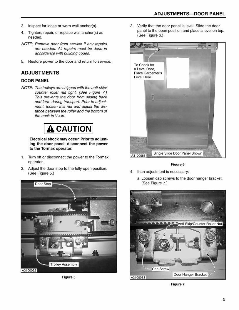
ADJUSTMENTS
DOOR PANEL
NOTE: The trolleys are shipped with the anti-skip/counter roller nut tight. (See Figure 7.)This prevents the door from sliding backand forth during transport. Prior to adjust-ment, loosen this nut and adjust the dis-tance between the roller and the bottom ofthe track to ¹/₁₆ in.
Electrical shock may occur. Prior to adjust-ing the door panel, disconnect the powerto the Tormax operator.
1. Turn off or disconnect the power to the Tormax operator.
2. Adjust the door stop to the fully open position.(See Figure 5.)
Figure 5
3. Verify that the door panel is level. Slide the door panel to the open position and place a level on top. (See Figure 6.)
Figure 6
4. If an adjustment is necessary:
a. Loosen cap screws to the door hanger bracket. (See Figure 7.)
Figure 7
Door Stop
Trolley Assembly
A3100032
Single Slide Door Panel ShownA3100088
To Check for a Level Door,Place Carpenter’sLevel Here
Cap Screw
Door Hanger BracketA3100033
Anti-Skip/Counter Roller Nut
5

ADJUSTMENTS—DOOR SEAL
b. Loosen the jam nut and thread the nut away from the hanger bracket. (See Figure 8.)
c. Turn adjusting screws until the door is level. (See Figure 8.)
Figure 8
NOTE: Do not adjust the door panel too low. This willcause too much friction between the doorguide and track. Excessive friction may causepremature wear of the Tormax operator.
The adjustments will be done to either theleft trolley, the right trolley, or both.
5. When the door panel is level, tighten the jam nut and cap screws.
Double-check that the power is turned offto the Tormax operator prior to checkingthe door bottom.
6. Check the position of the bottom edge of the door panel. The floor seal should make contact with the floor. It will be necessary for you to place your fin-gers between the seal and the floor to verify the position of the door. Do not judge the position by how the seal cover hangs from the door. (See Figure 9.)
Figure 9
7. Restore power to the Tormax operator.
DOOR SEAL
The following door seal adjustment is to be performed for the initial door start-up and maintenance follow-ups.
Prior to adjusting the door panel, discon-nect the power to the Tormax operator.
1. The seal-to-door clearance is adjusted fore and aft only.
a. Loosen the cap screw on both trolleys. (See Figure 10.)
Figure 10
b. Adjust the door as required and tighten hard-ware.
2. Restore power to the Tormax operator.
Jam Nut
Adjusting ScrewA3100034
NOTE: After Adjustment, Checkthat Door Is Not Bottomed Out
Floor Seal
A3100150
Cap Screw TrolleyA3100035
6

ADJUSTMENTS—SEAL STOP
SEAL STOP
The seal stop consists of two pieces: the wall jamb and the seal stop column. If there is a gap between the seal stop column and door panel seal, take note of how much you should adjust the seal stop prior to removing the door. The door panel seal should be snug against the seal stop column as shown in Figure 11.
Figure 11
1. Turn off or disconnect power to the Tormax opera-tor.
The door is heavy, and two people will berequired to remove the panel.
To avoid damaging the panel assembly, laythe panel flat on a foam cushion, or similarmaterial, for storage. Be extremely carefulnot to damage or crush the perimeterseals.
2. Loosen the door cap screw and remove the door. (See Figure 12.)
Figure 12
3. Loosen hardware and remove the door guide and the seal stop column. (See Figure 13.)
Figure 13
4. Loosen the hardware and adjust the wall jamb as required. (See Figure 14.)
Figure 14
5. Check that the wall jamb is level, tighten hardware, and install the seal stop column.
6. Install the door and adjust if required. See “DOOR PANEL” on page 5.
7. Restore power to the Tormax operator and check the seal stop.
Wall
Wall Anchor
Wall Jamb
Door Panel
Door Panel Seal
Seal Stop Column
A3100174
A3100035Cap Screw Trolley
A3100207
Seal Stop Column
Door Guide
Note: Wall Jamb Is Locatedunder Seal Stop Column
Wall Jamb
Head Assembly
Access HoleSlot
A3100204
7

MISCELLANEOUS—BELT TENSION (SINGLE AND BI-PARTING)
BELT TENSION (SINGLE AND BI-PARTING)
The belt tension is set at the factory. If the belt starts skipping or if the door is not operating smoothly and effi-ciently, an adjustment is required.
NOTE: If the door is operating in a erratic manner,check the drive belt to see if it is worn orfrayed prior to any adjustment.
DO NOT adjust belt tension by moving theTormax operator. This is set at the factoryfor your door size.
1. Turn off or disconnect power to Tormax operator.
2. Loosen the nut on the adjusting screw. (See Figure 15.)
3. Loosen the idler pulley screw.
4. Adjust the belt tension in the desired direction with the adjusting screw.
• Turn screw clockwise to tighten belt.
• Turn screw counterclockwise to loosen belt.
Figure 15
NOTE: If the belt has been adjusted properly andthere is no visible belt wear, the door itselfmay need adjusting. (See “DOOR PANEL”on page 5.)
5. Restore power to the Tormax operator.
MISCELLANEOUS
PANEL CLEANING
With all adjustments to the door complete, clean both sides of each panel with a general household surface cleaner using a clean, soft cloth.
Adjusting Screw
Nut Idler Pulley Screw
A3100148
8

PARTS LIST—PARTS ORDERING INFORMATION
PARTS LIST
PARTS ORDERING INFORMATION
How to Order Parts
1. Identify the parts required by referring to the follow-ing pages for part numbers and part descriptions.
2. To place an order, contact your local Rytec repre-sentative or the Rytec Customer Support Depart-ment at 1-800-628-1909 or 262-677-2058 (fax).
3. To ensure the correct parts are shipped, please include the serial number of your door with the order.
DOOR SERIAL NUMBER(S)
The DOOR SERIAL NUMBER is located on the left side of the head assembly, behind the hood. (See Figure 20 and Figure 21.)
IMPORTANT: When installing multiple doorsof the same model but in differ-ent sizes, verify serial number inthe head assembly.
Figure 20
Figure 21
Substitute Parts
Due to special engineering and product enhancement, the actual parts used on your door may be different from those shown in this manual.
Also, if a part has been improved in design and bears a revised part number, the improved part will be substi-tuted for the part ordered.
Return of Parts
Rytec will not accept the return of any parts unless they are accompanied by a Return Merchandise Authoriza-tion (RMA) form.
Before returning any parts, you must first contact the Rytec Customer Support Department to obtain authori-zation and an RMA form.
A3100224
End
HeadAssembly
Seal Stop Column
Column
Tormax Control Drive withHood Half Removed
Door Panel
with Wall Jamb
Door Panel
A3100223
Head Assembly
Tormax Control Drive with
Seal StopColumn withWall Jamb
Hood Half Removed
11

PARTS LIST—SINGLE SLIDE DOOR
SINGLE SLIDE DOOR
Figure 22
A3100213
7
10
8
3
9
28
26
27
11
2
4, 12
29
19
17
16
22
30
24
21
2320
30
18
1
14
15
22
25
13
12

PARTS LIST—SINGLE SLIDE DOOR
A/R = as required
N/A = not applicable to this assembly
* Items are produced based on manufactured height andwidth of door.
ITEM QTY. PART # DESCRIPTION
1* 1 Consult Factory Assy, 1 Piece HeaderConsult Factory Assy, 2 Piece Header
2 1 11200070 Splice, Hood Header, SS3 1 11200160 Splice, Header
(Back Side of 2 Piece Header)
4 2 55500230 Screw, #6-32 x .188 BHCS, SS
5 A/R S553103 Nut, ¹/₄-20 UNC, Serrated Flange, 18-8 SS
6 A/R S021792 Screw, ¹/₄-20 UNC x ¹/₂, BHCS, SS
7* 1 11200191 Hood, LH8* 1 11200192 Hood, RH9 1 11200381 Hood End, LH10 1 11200382 Hood End, RH11 1 Consult Factory Tormax Operator12 1 11200610 Tormax Control Assembly13* 1 Consult Factory TEP Drive Belt
Consult Factory TXP Heavy Duty Drive Belt14 1 0016333 Decal, Serial Number
Plate15 A/R SL0594 Trolley, Zinc
SL0464 Trolley, Heavy Duty Zinc16 1 11200400 Jamb, Wall Center17 1 11200200 Jamb, Wall End18 1 11200132 Jamb Cover, Column End,
RH 11200131 Jamb Cover, Column End,
LH19 1 11200121 Jamb Cover, Stop Seal, LH
11200122 Jamb Cover, Stop Seal, RH20 2 S021781 Screw, 10-24 UNC x 1.00
Long, SHCS21 2 S021867 Nut, 10-24 UNC, Nylock,
SS22 6 S550288 PTMS, 10-24 UNC x ³/₄, SS23 1 SL0065 Track, Guide24 A/R 11200930 Spacer, Guide25 1 Consult Factory Panel, Door Assembly26 1 Consult Factory Seal, Stop27 1 Consult Factory Seal, End Column28 1 0007830 Seal, Floor29 1 11200980 Seal, Top30 2 11201650 Photoeye Set, TORMAX
13
ALWAYS INCLUDE SERIAL NUMBER OF DOOR WHEN PLACING ORDERTo ensure you receive the correct parts when placing an order, always include the serial number of your door. Also,due to product enhancement, the actual parts on your door may be different from those shown in this manual.
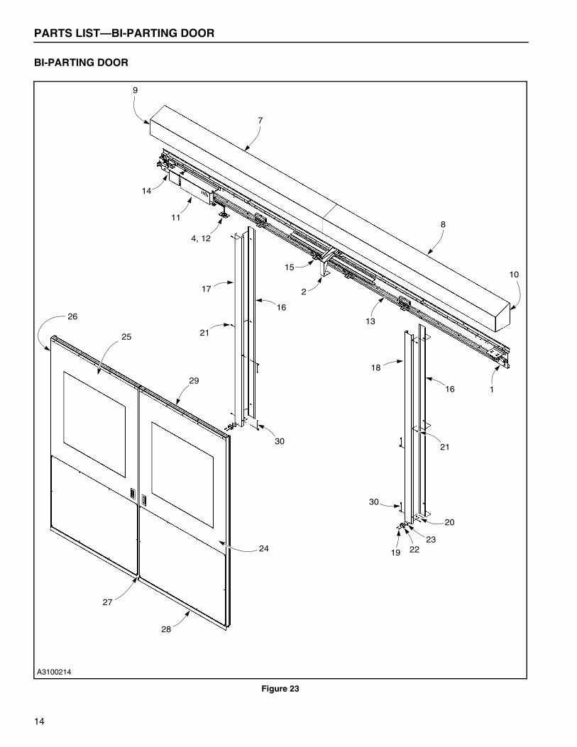
PARTS LIST—BI-PARTING DOOR
BI-PARTING DOOR
Figure 23
A3100214
7
4, 12
1
8
10
9
2
11
13
14
15
16
16
17
30
19 2223
20
21
21
30
18
26
25
29
24
28
27
14

PARTS LIST—BI-PARTING DOOR
A/R = as required
N/A = not applicable to this assembly
* Items are produced based on manufactured height andwidth of door.
ITEM QTY. PART # DESCRIPTION
1* 1 Consult Factory Assy, 1 Piece HeaderConsult Factory Assy, 2 Piece Header
2 1 11200070 Splice, Hood Header, SS3 1 11200160 Splice, Header
(Back Side of 2 Piece Header)
4 2 55500230 Screw, #6-32 x .188 BHCS, SS
5 A/R S553103 Nut, ¹/₄-20 UNC, Serrated Flange, 18-8 SS
6 A/R S021792 Screw, ¹/₄-20 UNC x ¹/₂, BHCS, SS
7* 1 11200191 Hood, LH8* 1 11200192 Hood, RH9 1 11200381 Hood End, LH10 1 11200382 Hood End, RH11 1 Consult Factory Tormax Operator12 1 11200610 Tormax Control Assembly13* 1 Consult Factory TEP Drive Belt
Consult Factory TXP Heavy Duty Drive Belt14 1 0016333 Decal, Serial Number
Plate15 A/R SL0594, SL0595 Trolley, Zinc
SL0464, SL0493 Trolley, Heavy Duty Zinc16 2 11200400 Jamb, Wall Center17 1 11200121 Jamb Cover, Stop Seal, LH18 1 11200122 Jamb Cover, Stop Seal, RH19 4 S021781 Screw, 10-24 UNC x 1.00
Long, SHCS20 4 S021867 Nut, 10-24 UNC, Nylock,
SS21 6 S550288 PTMS, 10-24 UNC x ³/₄, SS22 2 SL0065 Track, Guide23 A/R 11200930 Spacer, Guide24 1 Consult Factory Panel, Door Assembly, RH25 1 Consult Factory Panel, Door Assembly, LH26 1 Consult Factory Seal, Stop27 1 Consult Factory Seal, End28 1 0007830 Seal, Floor29 1 11200980 Seal, Top30 2 11201650 Photoeye Set, TORMAX
15
ALWAYS INCLUDE SERIAL NUMBER OF DOOR WHEN PLACING ORDERTo ensure you receive the correct parts when placing an order, always include the serial number of your door. Also,due to product enhancement, the actual parts on your door may be different from those shown in this manual.

NOTES
16

