perkins 1300 series - e-genset catalogs€¦ · perkins 1300 series (diagnostic w/o diag tool) some...
TRANSCRIPT

PERKINS 1300 SERIES
(Diagnostic w/o DIAG TOOL)
Some Perkins engine are fitted with a self-test system, which can be used to check for active and inactive faults. It will also check all outputs for open circuit.
Two types of faults are found by the engine control module (ECM) and retained in its memory, they are active faults and inactive faults. Active faults and inactive faults are shown on the diagnostic tool as “ACTIVE CODES” and “INACTIVE CODES”.
An active fault is one that was found by the engine control module and has not been repaired. When an active fault has been repaired, it becomes an inactive fault after 15 seconds.
An inactive fault is one that was an active fault at some time, but is not present now. This could be because it was repaired, or it is an intermittent fault.
The self-test system should be fitted to every application, it can be used to find faults in the engine management system. A special diagnostic tool is necessary to operate the full range of diagnostic tests on the engine management system. (Please refer to the Workshop Manual TPD 1353 E)
View of Zordan’s dashboard:
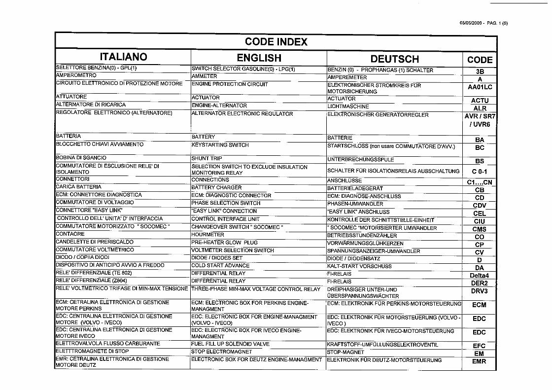
In order to understand the meaning of the lights & buttons installed by Zordan on the dashboard, you need to refer to the file « CODE INDEX ZORDAN ».
H1 = ECM: FAULT-WARNING LIGHTS
H2 = ECM: FAULT-WARNING LIGHTS
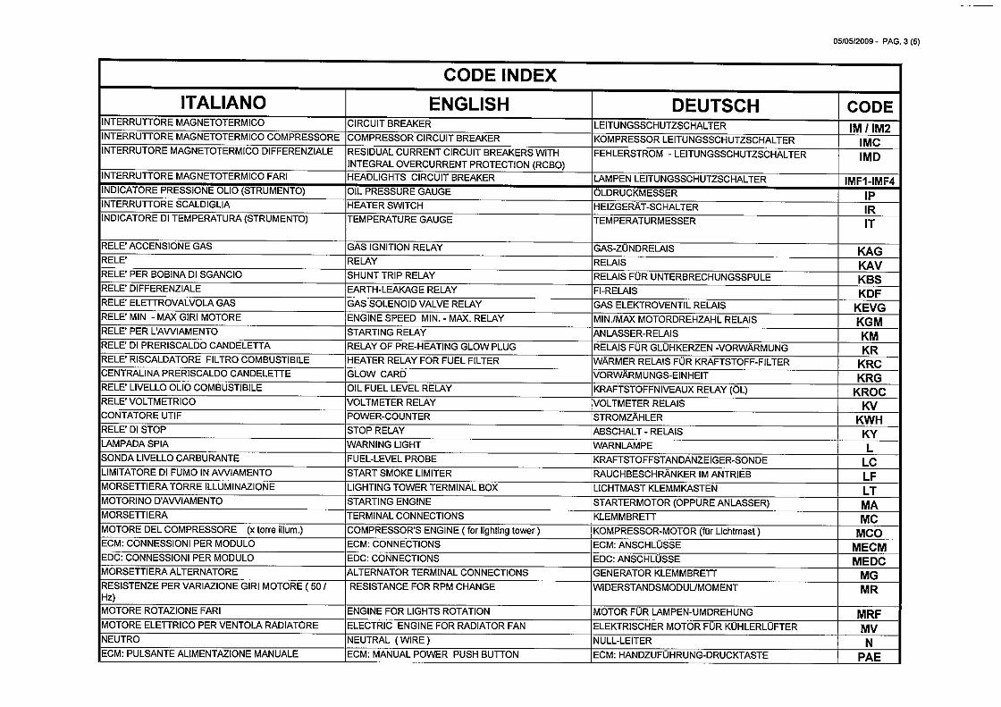
PD = ECM: SELF TEST INPUT/DIAGNOSTIC START PUSH BUTTON
PAE = ECM: MANUAL POWER PUSH BUTTON
How to check for faults codes? (Operation 17-1) The self-test system usually consists of a button, an orange lamp and a red lamp.
1. Set the start switch to the ‘ON’ position, but do not start the engine. 2. Press the self-test button (PD) once.
Notes:
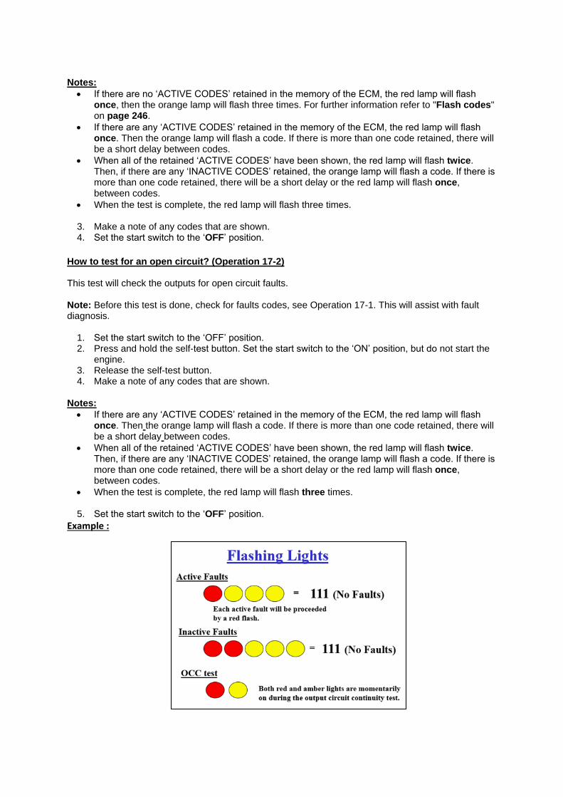
If there are no ‘ACTIVE CODES’ retained in the memory of the ECM, the red lamp will flash once, then the orange lamp will flash three times. For further information refer to "Flash codes" on page 246.
If there are any ‘ACTIVE CODES’ retained in the memory of the ECM, the red lamp will flash once. Then the orange lamp will flash a code. If there is more than one code retained, there will be a short delay between codes.
When all of the retained ‘ACTIVE CODES’ have been shown, the red lamp will flash twice. Then, if there are any ‘INACTIVE CODES’ retained, the orange lamp will flash a code. If there is more than one code retained, there will be a short delay or the red lamp will flash once, between codes.
When the test is complete, the red lamp will flash three times.
3. Make a note of any codes that are shown. 4. Set the start switch to the ‘OFF’ position.
How to test for an open circuit? (Operation 17-2) This test will check the outputs for open circuit faults. Note: Before this test is done, check for faults codes, see Operation 17-1. This will assist with fault diagnosis.
1. Set the start switch to the ‘OFF’ position. 2. Press and hold the self-test button. Set the start switch to the ‘ON’ position, but do not start the
engine. 3. Release the self-test button. 4. Make a note of any codes that are shown.
Notes:
If there are any ‘ACTIVE CODES’ retained in the memory of the ECM, the red lamp will flash once. Then the orange lamp will flash a code. If there is more than one code retained, there will be a short delay between codes.
When all of the retained ‘ACTIVE CODES’ have been shown, the red lamp will flash twice. Then, if there are any ‘INACTIVE CODES’ retained, the orange lamp will flash a code. If there is more than one code retained, there will be a short delay or the red lamp will flash once, between codes.
When the test is complete, the red lamp will flash three times.
5. Set the start switch to the ‘OFF’ position.
Example :

When you’ve got the « Active code », you should search the correspondence on the file « Flash
Codes », page 246. (Please refer to the Workshop Manual TPD 1353 E)
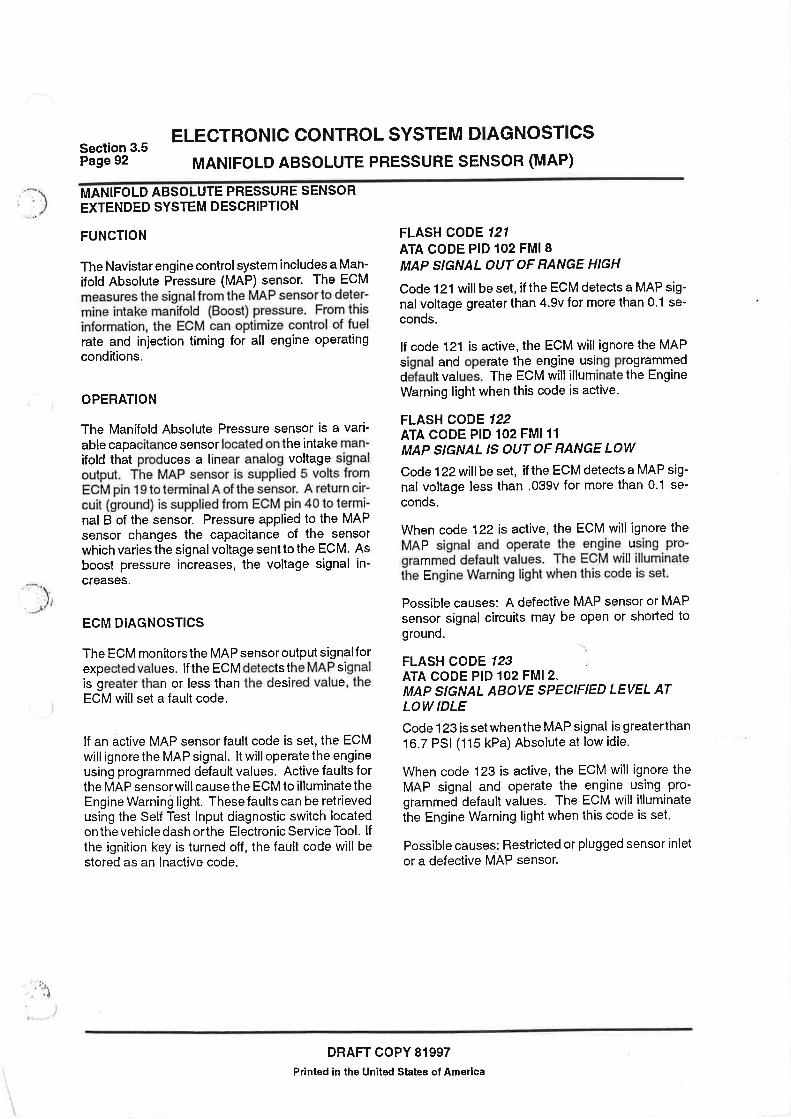
For example, an active code « 121 » would be related to the following problem:
Then, as per the code indicated, you need to look for the fault, as per indicated. If it comes from a
sensor, refer to the data below.
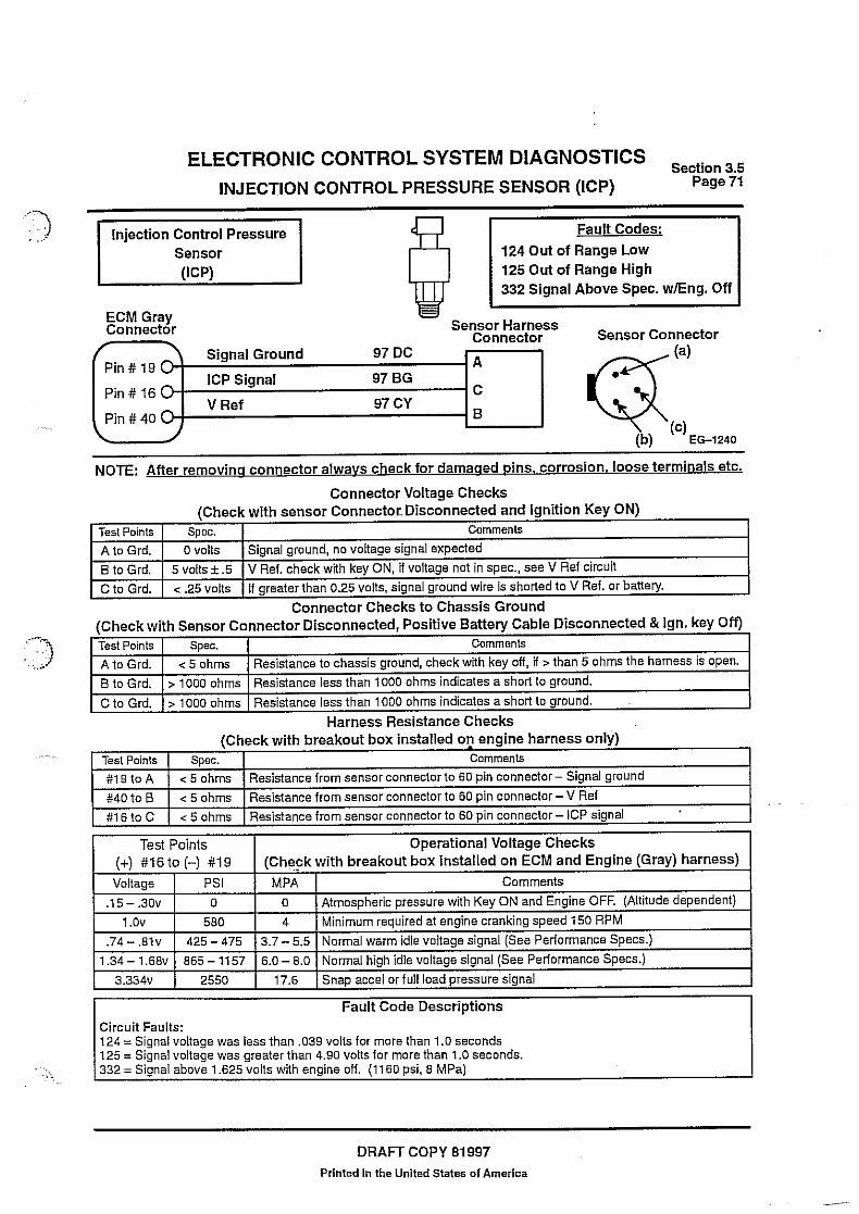
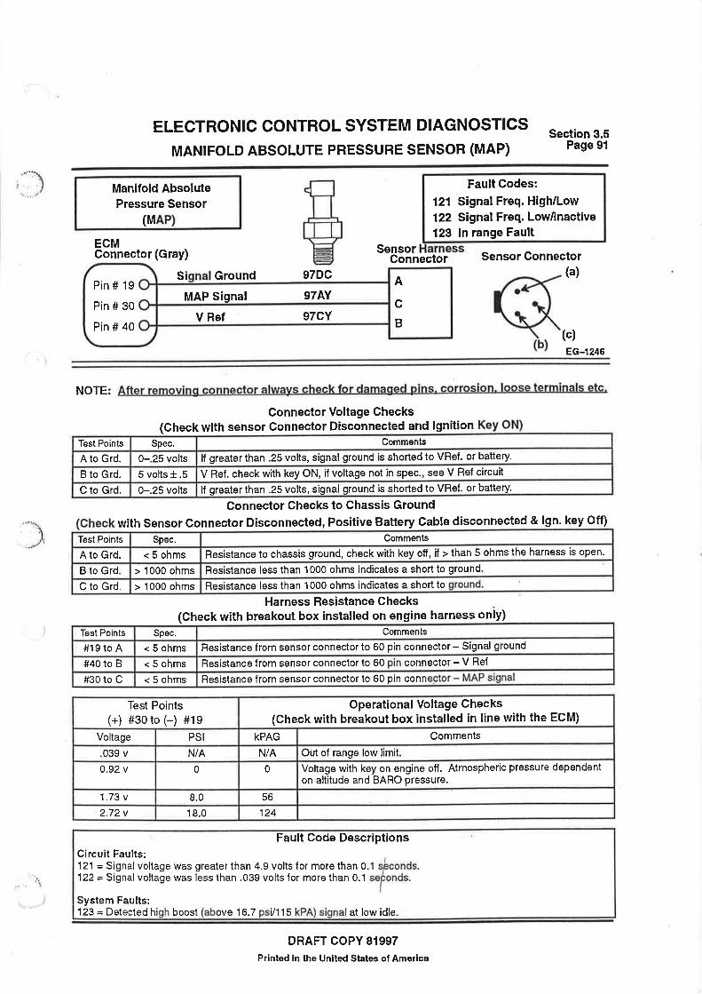
Variable capacitance sensors: Variable capacitance sensors are used to measure pressure. Changes in pressure will cause changes to the signal from the sensor. They are the sensors for:
Manifold absolute pressure (MAP)
Engine oil pressure (EOP) (A4)
Injection control pressure (ICP) (A5)
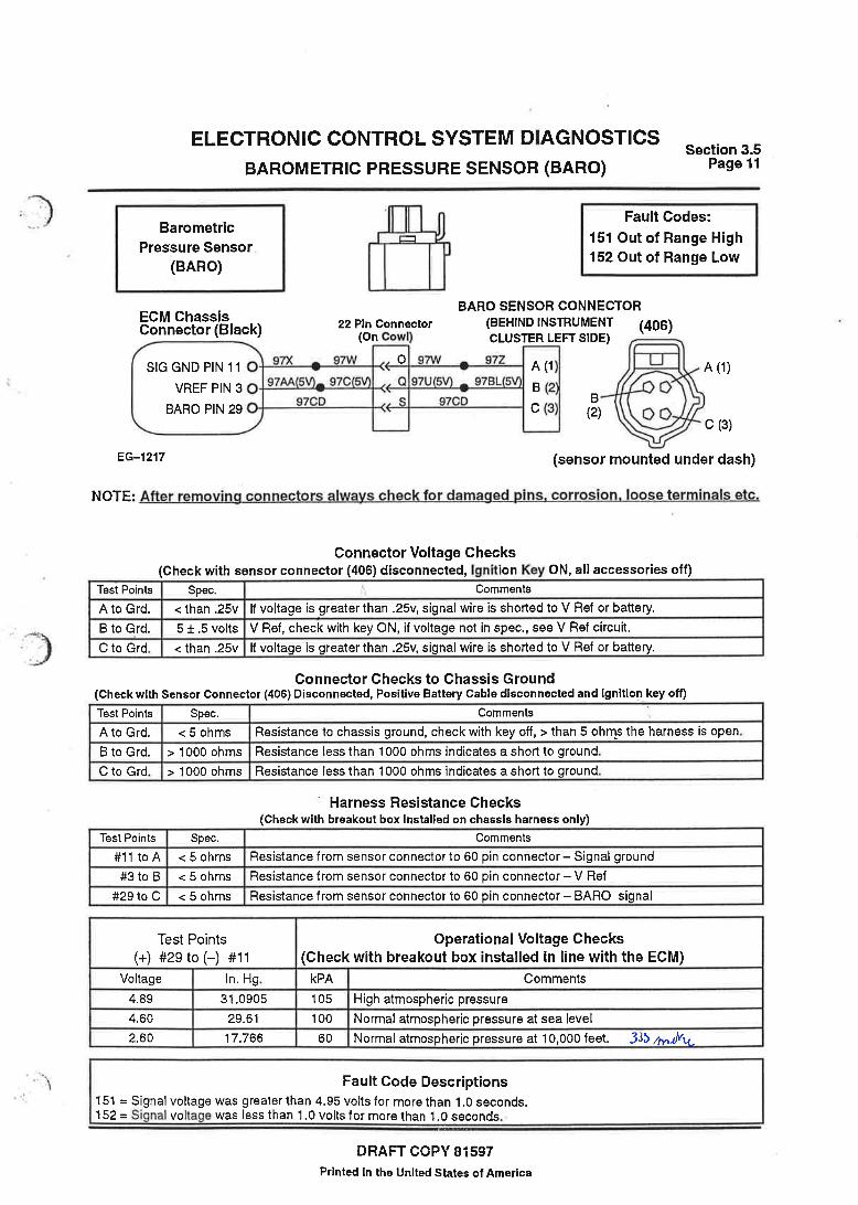
Barometric pressure (BARO) (A8). Thermistors: Thermistors are used to measure temperature. They are the sensors for:
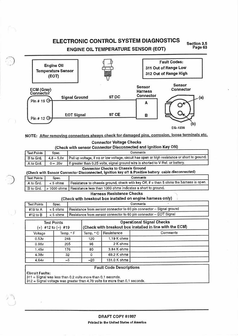
Engine oil temperature (EOT) (A3)
Coolant temperature (ECT) (A6)
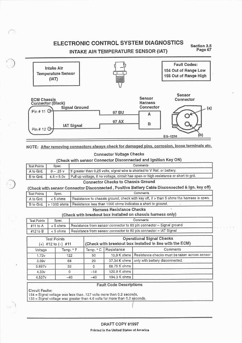
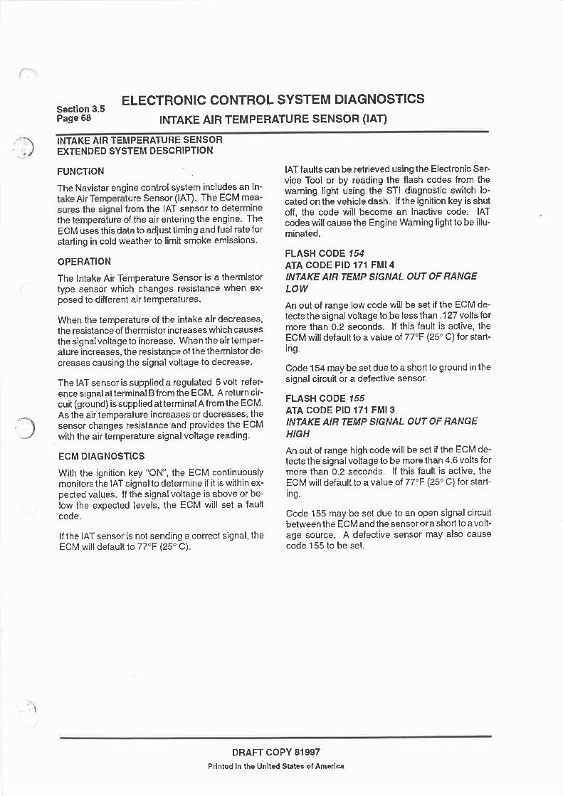
Inlet air temperature (IAT) (A9).
RVFM Roduit Benoit
14
204 Workshop Manual, TPD 1353E, Issue 3
Peregrine EDi and 1300 Series EDiEngine management system
General description
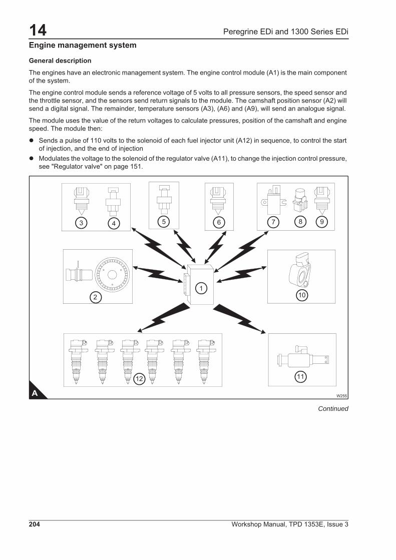
The engines have an electronic management system. The engine control module (A1) is the main component of the system.
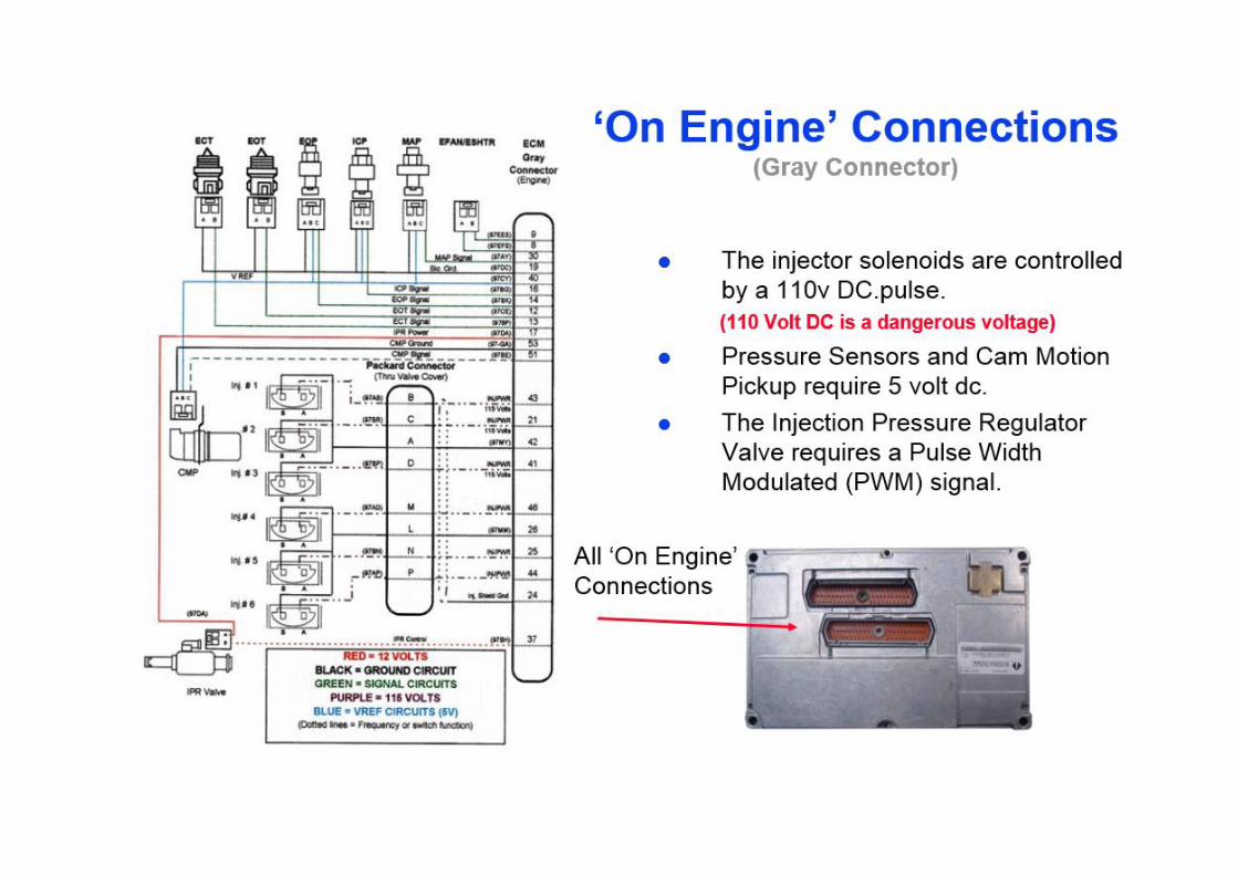
The engine control module sends a reference voltage of 5 volts to all pressure sensors, the speed sensor and the throttle sensor, and the sensors send return signals to the module. The camshaft position sensor (A2) will send a digital signal. The remainder, temperature sensors (A3), (A6) and (A9), will send an analogue signal.
The module uses the value of the return voltages to calculate pressures, position of the camshaft and engine speed. The module then:
� Sends a pulse of 110 volts to the solenoid of each fuel injector unit (A12) in sequence, to control the start of injection, and the end of injection
� Modulates the voltage to the solenoid of the regulator valve (A11), to change the injection control pressure, see "Regulator valve" on page 151.
Continued
W255
12
3 4 5 6 87 9
10
11
1
A
2
14
Workshop Manual, TPD 1353E, Issue 3 205
Peregrine EDi and 1300 Series EDi
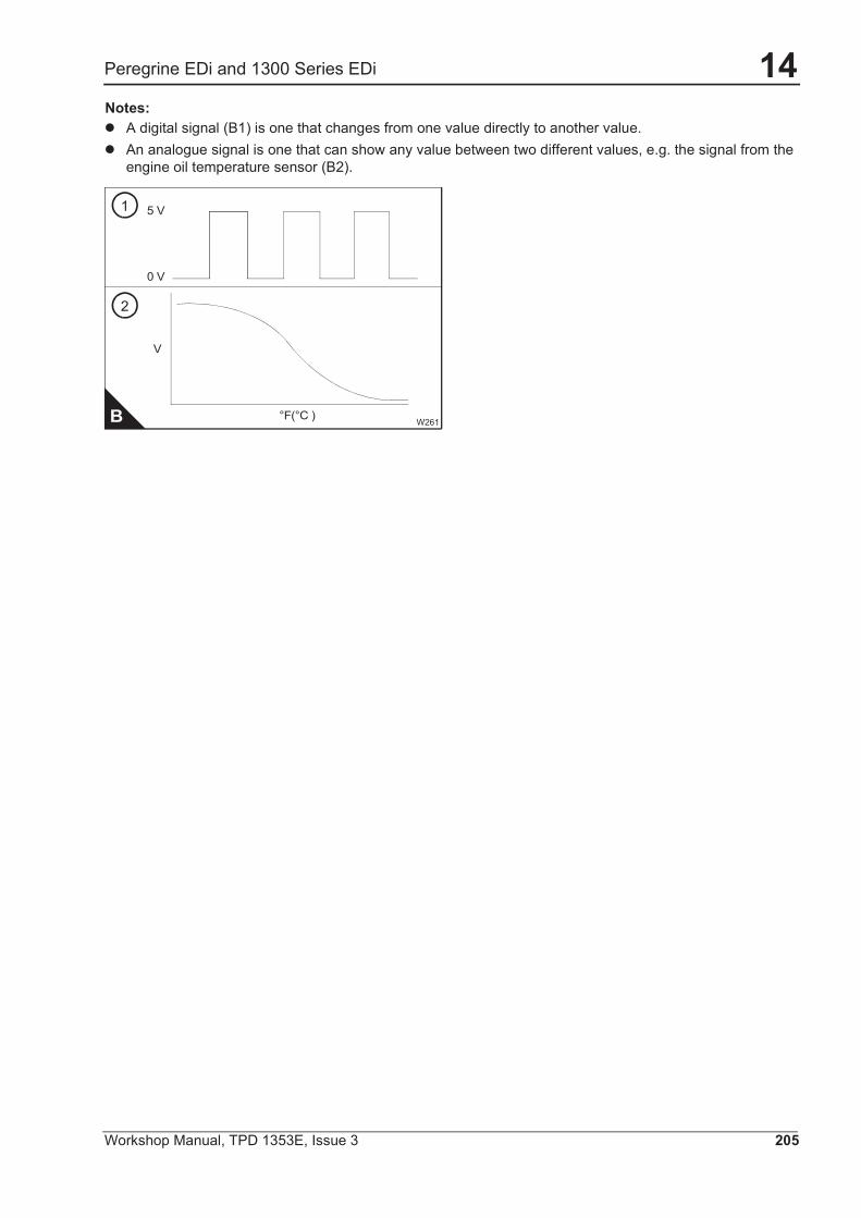
Notes:� A digital signal (B1) is one that changes from one value directly to another value.� An analogue signal is one that can show any value between two different values, e.g. the signal from the
engine oil temperature sensor (B2).
W261B
V
0 V
5 V
2
1
°F(°C )
14
206 Workshop Manual, TPD 1353E, Issue 3
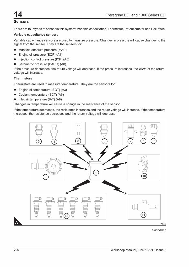
Peregrine EDi and 1300 Series EDiSensors
There are four types of sensor in this system: Variable capacitance, Thermistor, Potentiometer and Hall-effect.
Variable capacitance sensors
Variable capacitance sensors are used to measure pressure. Changes in pressure will cause changes to the signal from the sensor. They are the sensors for:
� Manifold absolute pressure (MAP)� Engine oil pressure (EOP) (A4)� Injection control pressure (ICP) (A5)� Barometric pressure (BARO) (A8).If the pressure decreases, the return voltage will decrease. If the pressure increases, the value of the return voltage will increase.
Thermistors
Thermistors are used to measure temperature. They are the sensors for:
� Engine oil temperature (EOT) (A3)� Coolant temperature (ECT) (A6)� Inlet air temperature (IAT) (A9).Changes in temperature will cause a change in the resistance of the sensor.
If the temperature decreases, the resistance increases and the return voltage will increase. If the temperature increases, the resistance decreases and the return voltage will decrease.
Continued
W255
12
3 4 5 6 87 9
10
11
1
A
2
14
Workshop Manual, TPD 1353E, Issue 3 207
Peregrine EDi and 1300 Series EDiPotentiometers
A potentiometer is used to measure the position of a mechanical device - the throttle.
The speed control (page 206/A10) is connected to a potentiometer, changes in its position will cause a change in the signal voltage of the potentiometer.
� If the return voltage increases, the engine speed will increase.� If the return voltage decreases, the engine speed will decrease.The signal from the speed control sensor does not assist with calculating engine speed, it only shows the position of the speed control.
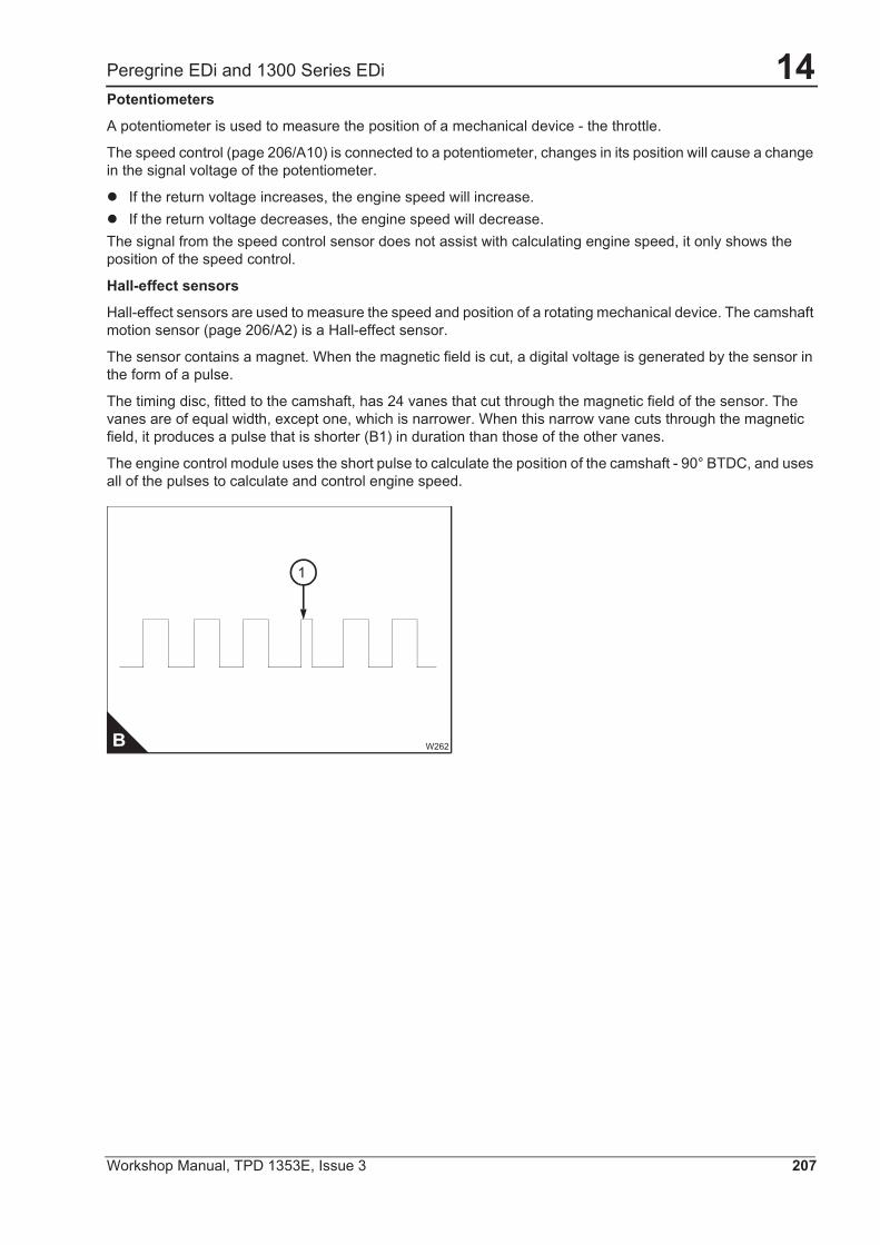
Hall-effect sensors
Hall-effect sensors are used to measure the speed and position of a rotating mechanical device. The camshaft motion sensor (page 206/A2) is a Hall-effect sensor.
The sensor contains a magnet. When the magnetic field is cut, a digital voltage is generated by the sensor in the form of a pulse.
The timing disc, fitted to the camshaft, has 24 vanes that cut through the magnetic field of the sensor. The vanes are of equal width, except one, which is narrower. When this narrow vane cuts through the magnetic field, it produces a pulse that is shorter (B1) in duration than those of the other vanes.
The engine control module uses the short pulse to calculate the position of the camshaft - 90° BTDC, and uses all of the pulses to calculate and control engine speed.
W262B
1
14
208 Workshop Manual, TPD 1353E, Issue 3
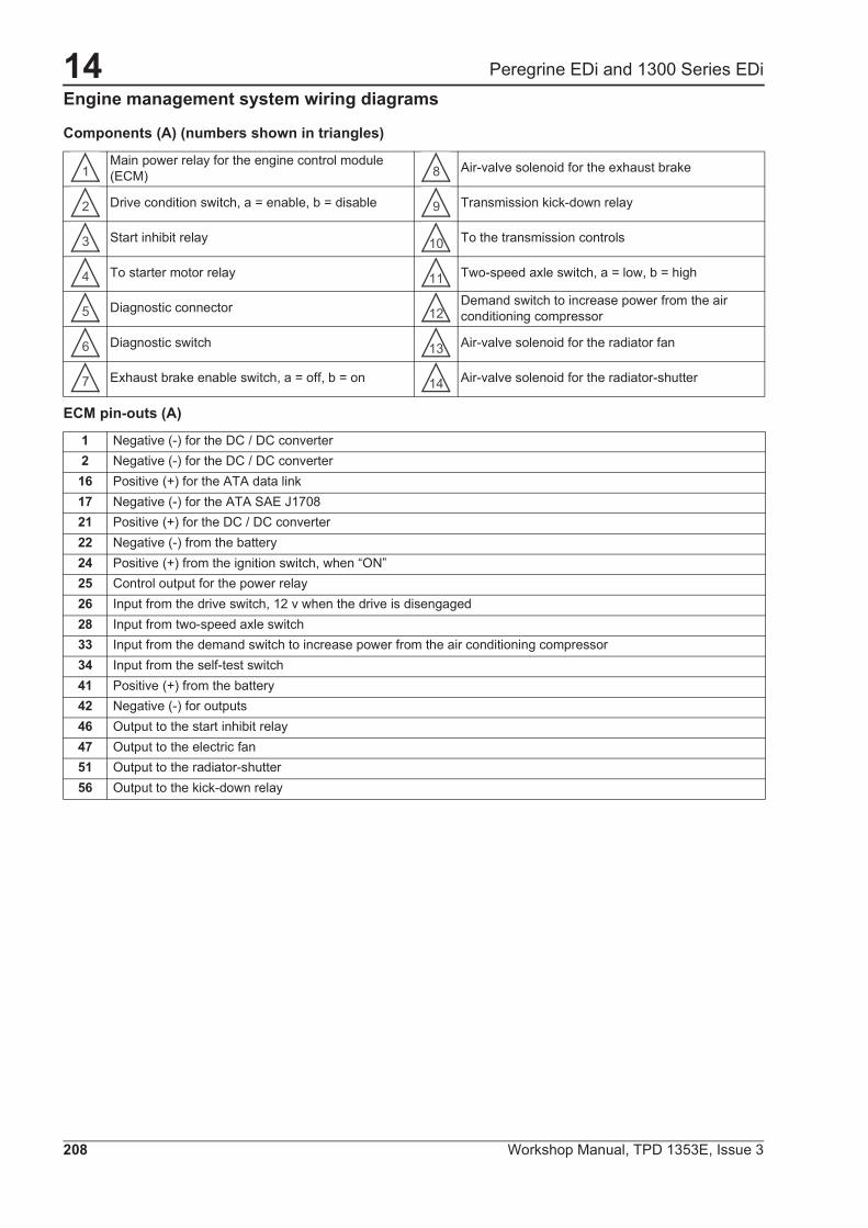
Peregrine EDi and 1300 Series EDiEngine management system wiring diagrams
Components (A) (numbers shown in triangles)
ECM pin-outs (A)
Main power relay for the engine control module (ECM) Air-valve solenoid for the exhaust brake
Drive condition switch, a = enable, b = disable Transmission kick-down relay
Start inhibit relay To the transmission controls
To starter motor relay Two-speed axle switch, a = low, b = high
Diagnostic connector Demand switch to increase power from the air conditioning compressor
Diagnostic switch Air-valve solenoid for the radiator fan
Exhaust brake enable switch, a = off, b = on Air-valve solenoid for the radiator-shutter
1 Negative (-) for the DC / DC converter2 Negative (-) for the DC / DC converter16 Positive (+) for the ATA data link17 Negative (-) for the ATA SAE J170821 Positive (+) for the DC / DC converter22 Negative (-) from the battery24 Positive (+) from the ignition switch, when “ON”25 Control output for the power relay26 Input from the drive switch, 12 v when the drive is disengaged28 Input from two-speed axle switch33 Input from the demand switch to increase power from the air conditioning compressor34 Input from the self-test switch41 Positive (+) from the battery 42 Negative (-) for outputs46 Output to the start inhibit relay47 Output to the electric fan51 Output to the radiator-shutter56 Output to the kick-down relay
1 8
2 9
3 10
4 11
5 12
6 13
7 14
14
Workshop Manual, TPD 1353E, Issue 3 209
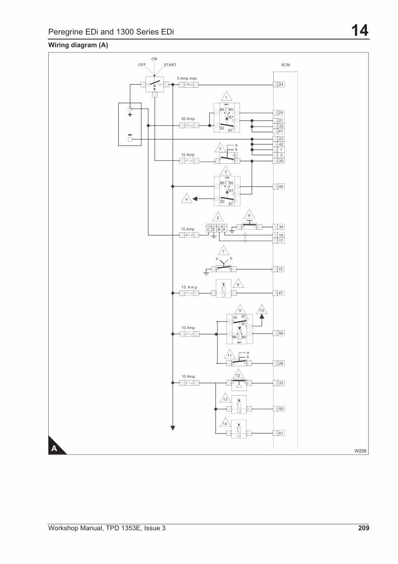
Peregrine EDi and 1300 Series EDiWiring diagram (A)
A W256
12
B AEC
10 A m p
4
1
2
3
10
6
7
8
9
5
ab
a b
ab
OFFON
START
5 Amp max24
ECM
30 Amp
30
86
87
87
8025
21
4122
25
4223
10 Amp
46
30 87
86
87
80
10 Amp1617
34
15
47
10 Amp
30 87
86
87
80
11
56
50
33
28
13
1210 Amp
14
51

14
210 Workshop Manual, TPD 1353E, Issue 3
Peregrine EDi and 1300 Series EDiComponents (B) (numbers shown in triangles)
Brake switch number 1, a = off, b = on Warning light to show that the pressure control mode is active
Brake switch number 2, a = off, b = on Remote speed control sensor
Cruise-control, a = off, b = on Hydraulic pressure switch
Remote PTO switch, a = on, b = off Accelerator pedal position sensor
Speed switch, a = reset accelerator, b = set coast Barometric absolute pressure sensor
Speed switch, remote, a = reset accelerator, b = set coast Ambient air temperature sensor
Pre-set speed switch, a = off, b = on Vehicle speed sensor
Variable speed switch, a = off, b = on Instrumentation
Hydraulic pressure governor switch, a = off, b = on Coolant level switch
Hydraulic pressure governor control relay Computer data link connector
Warning light to show that the speed control mode is active
1 12
2 13
3 14
4 15
5 16
6 17
7 18
8 19
9 20
10 21
11

14
Workshop Manual, TPD 1353E, Issue 3 211
Peregrine EDi and 1300 Series EDiWiring diagram (B)
B W257
1
7
8
b
a
6
1
2
4
a
5ba
3
9
4
3
2
CA
B
3
5
6
7
8
9
b
a b
b
a
ba
a
a
b
b
10 Amp
10 Amp
ECM
10 Amp
10 Amp
1110
12
86 80
873087
18
17
15
14
13
16
19
21
20
31
35
43
44
32
3852
14
36
37
49
30
13
27
11
12
40
29
39
48
54 45
57
5355
59
58 60
18
20
10
19
14
212 Workshop Manual, TPD 1353E, Issue 3
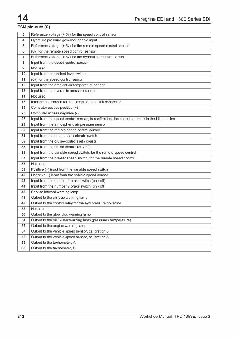
Peregrine EDi and 1300 Series EDiECM pin-outs (C)
3 Reference voltage (+ 5v) for the speed control sensor4 Hydraulic pressure governor enable input5 Reference voltage (+ 5v) for the remote speed control sensor6 (0v) for the remote speed control sensor7 Reference voltage (+ 5v) for the hydraulic pressure sensor8 Input from the speed control sensor9 Not used10 Input from the coolant level switch11 (0v) for the speed control sensor12 Input from the ambient air temperature sensor13 Input from the hydraulic pressure sensor14 Not used18 Interference screen for the computer data link connector19 Computer access positive (+)20 Computer access negative (-)27 Input from the speed control sensor, to confirm that the speed control is in the idle position29 Input from the atmospheric air pressure sensor30 Input from the remote speed control sensor31 Input from the resume / accelerate switch32 Input from the cruise-control (set / coast)35 Input from the cruise-control (on / off)36 Input from the variable speed switch, for the remote speed control37 Input from the pre-set speed switch, for the remote speed control38 Not used39 Positive (+) input from the variable speed switch40 Negative (-) input from the vehicle speed sensor43 Input from the number 1 brake switch (on / off)44 Input from the number 2 brake switch (on / off)45 Service interval warning lamp48 Output to the shift-up warning lamp49 Output to the control relay for the hyd pressure governor52 Not used53 Output to the glow plug warning lamp54 Output to the oil / water warning lamp (pressure / temperature)55 Output to the engine warning lamp57 Output to the vehicle speed sensor, calibration B58 Output to the vehicle speed sensor, calibration A59 Output to the tachometer, A60 Output to the tachometer, B
14
Workshop Manual, TPD 1353E, Issue 3 213
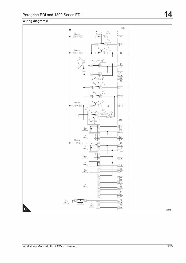
Peregrine EDi and 1300 Series EDiWiring diagram (C)
C W257
1
7
8
b
a
6
1
2
4
a
5ba
3
9
4
3
2
CA
B
3
5
6
7
8
9
b
a b
b
a
ba
a
a
b
b
10 Amp
10 Amp
ECM
10 Amp
10 Amp
1110
12
86 80
873087
18
17
15
14
13
16
19
21
20
31
35
43
44
32
3852
14
36
37
49
30
13
27
11
12
40
29
39
48
54 45
57
5355
59
58 60
18
20
10
19
17
246 Workshop Manual, TPD 1353E, Issue 3
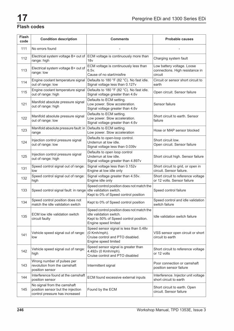
Peregrine EDi and 1300 Series EDiFlash codes
Flash code Condition description Comments Probable causes
111 No errors found - -
112 Electrical system voltage B+ out of range: high
ECM voltage is continuously more than 18v Charging system fault
113 Electrical system voltage B+ out of range: low
ECM voltage is continuously less than 6.5v.Cause of no start/misfire
Low battery voltage. Loose connections. High resistance in circuit
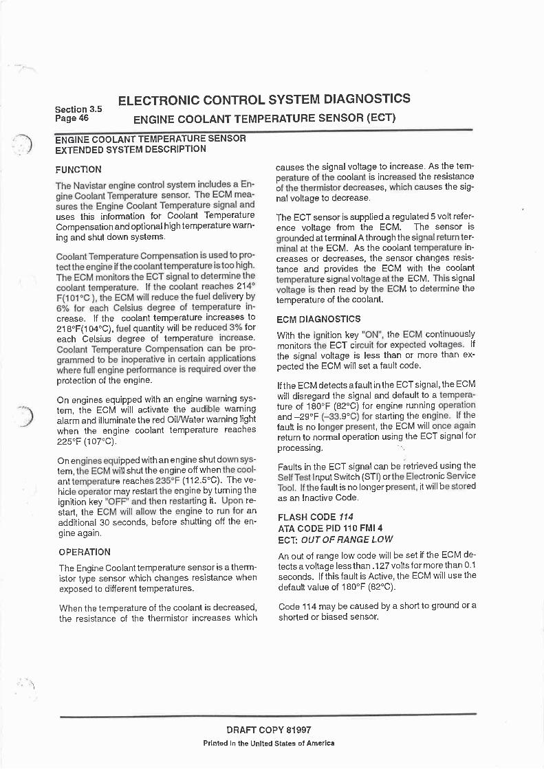
114 Engine coolant temperature signal out of range: low
Defaults to 180 °F (82 °C). No fast idle.Signal voltage less than 0.127v
Circuit or sensor short circuit to earth
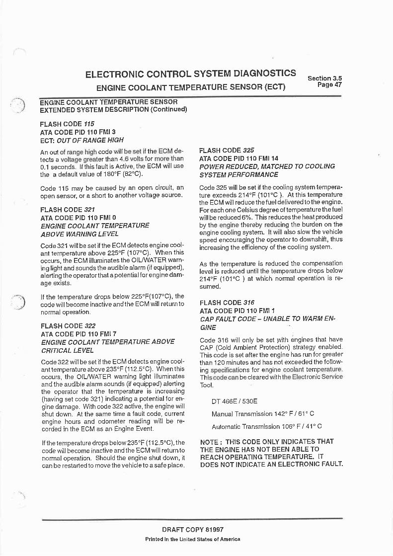
115 Engine coolant temperature signal out of range: high
Defaults to 180 °F (82 °C). No fast idle.Signal voltage greater than 4.6v Open circuit. Sensor failure
121 Manifold absolute pressure signal out of range: high
Defaults to ECM setting.Low power. Slow acceleration.Signal voltage greater than 4.6v
Sensor failure
122 Manifold absolute pressure signal out of range: low
Defaults to ECM setting.Low power. Slow acceleration.Signal voltage greater than 4.6v
Short circuit to earth. Sensor failure
123 Manifold absolute pressure fault: in range
Defaults to ECM setting.Low power. Slow acceleration Hose or MAP sensor blocked
124 Injection control pressure signal out of range: low
Defaults to open-loop control.Underrun at low idle.Signal voltage less than 0.039v
Short circuit low.Open circuit. Sensor failure
125 Injection control pressure signal out of range: high
Defaults to open loop controlUnderrun at low idle.Signal voltage greater than 4.897v
Short circuit high. Sensor failure
131 Speed control signal out of range: low
Signal voltage less than 0.152vEngine at low idle only
Short circuit to grid, or open in circuit. Sensor failure.
132 Speed control signal out of range: high
Signal voltage greater than 4.55v.Engine idle only
Short circuit to reference voltage or 12 volts. Sensor failure
133 Speed control signal fault: in rangeSpeed control position does not match the idle validation switch.Kept to 0% of Speed control position
Speed control failure
134 Speed control position does not match the idle validation switch Kept to 0% of Speed control position Speed control and idle validation
switch failure
135 ECM low idle validation switch circuit faulty
Speed control position does not match the idle validation switch.Kept to 50% of Speed control position.Engine speed limited
Idle validation switch failure
141 Vehicle speed signal out of range: low
Speed sensor signal is less than 0.48v (0 Kmh/mph).Cruise control and PTO disabled.Engine speed limited
VSS sensor open circuit or short circuit to earth
142 Vehicle speed signal out of range: high
Speed sensor signal is greater than 4.492v (0 Kmh/mph).Cruise control and PTO disabled
Short circuit to reference voltage or 12 volts
143Wrong number of pulses per revolution from the camshaft position sensor
Intermittent signal Poor connection or camshaft position sensor failure
144 Interference found at the camshaft position sensor ECM found excessive external inputs Interference. Injector unit voltage
short circuit to earth
145No signal from the camshaft position sensor but the injection control pressure has increased
Found by the ECM Short circuit to earth. Open circuit. Sensor failure

17
Workshop Manual, TPD 1353E, Issue 3 247
Peregrine EDi and 1300 Series EDi
151 Barometric pressure signal out of range: high
Signal voltage greater than 4.9v for more than 1 second.Defaults to 101 kPa (14.7 lbf/in2)1,0 kgf/cm2
Short circuit high or open circuit. Sensor failure
152 Barometric pressure signal out of range: low
Signal voltage less than 1.0v for more than 1 second.Defaults to 101 kPa (14.7 lb/in2)1,0 kgf/cm2
Short circuit to earth low
154 Intake air temperature signal out of range: low
Signal voltage less than 0.127v.Defaults to 170 °F (77 °C) Short circuit to earth
155 Intake air temperature signal out of range: high
Signal voltage greater than 4.6v.Defaults to 170 °F (77 °C) Open circuit
161 A/C demand pressure signal out of range - high - A/C sensor short circuit - low or
open
162 A/C demand pressure signal out of range - low - A/C circuit shorted, high,
defective sensor
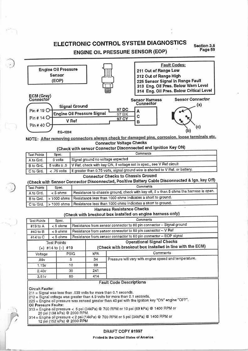
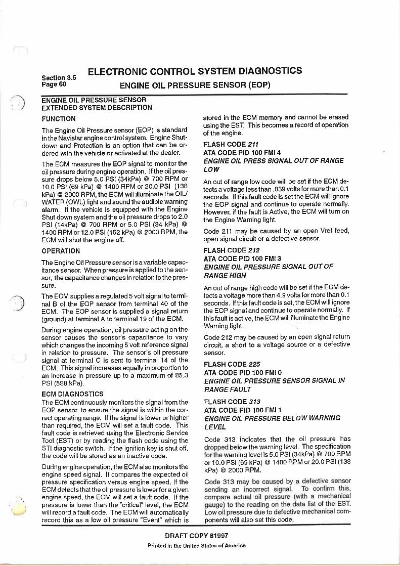
211(1) Engine oil pressure signal out of range: low Signal voltage less than 0.039v Short circuit to earth low
212(1) Engine oil pressure signal out of range: high Signal voltage greater than 4.9v Short circuit to earth high or open
circuit
213 Remote speed control out of range: low
Remote speed control signal less than 0.249v Open circuit
214 Remote speed control out of range: high
Remote speed control signal greater than 4.5v Short circuit to earth
215 Vehicle speed signal frequently out of range - high
Speedometer cruise PTO disabled, Engine RPM limited signal - irregular >4375 Hz
Incorrectly adjusted speed sensor , electrical noise on circuit
216 Hydraulic pressure signal out of range - low HPS signal voltage below 0.039v Circuit open, short to ground,
defective sensor
221 Cruise/PTO (or remote PTO) switch fault
Signal voltage incorrect, does not match the switch position
Short circuit or high resistance in the speed control circuit
222 Brake switch circuit fault Voltage to pins 43 and 44 on the ECM are not the same
Switch or relay faulty or incorrectly adjusted
224 Flash memory corrupt ECM memory loss Internal ECM problem
225 Sensor for engine oil pressure faulty: in range
Signal greater than 276 kPa (40 lbf/in2)2,8 kgf/cm2 with the engine start key in the “ON” position. Engine protection disabled
Faulty circuit connection. Sensor failure
226 Hydraulic pressure sensor signal out of range - high HPS signal above 4.9v Circuit short, high, defective
sensor
231 ATA data link fault ATA link open or short circuit. VPM fault ATA device earthed or overloaded
Unable to forward EMC message to ATA DCL Will not turn warning light on ATA Data link circuits shorted
high or low
233 Tachometer buffer is inactive VPM not receiving Tacho signal Circuit 97D open or shorted
234 Unable to forward ATA message to EMC Will not turn warning light on EST plugged in, W/key off and
VPM powered up
235 VPM/ECM DCL fault No ECM diagnostic replies DCL circuits 97AT and/or 97AS
236 Engine coolant level switch fault - Short circuit to earth or open circuit
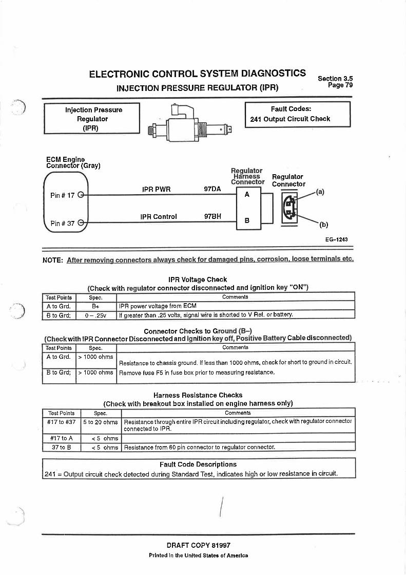
241Regulator for injection control pressure failed the output circuit test
Output circuit test in engine-off test only Open circuit or short circuit to earth
Flash code Condition description Comments Probable causes

17
248 Workshop Manual, TPD 1353E, Issue 3
Peregrine EDi and 1300 Series EDi
244 Engine data link failed open circuit test Output circuit test in engine-off test only Open circuit or short circuit to
earth
245 Exhaust pressure regulator OCC self test failed
EPR regulator - output circuit check - engine off test only Open or short circuit
246 Engine fan - DCC self test fault Fan relay - output circuit check - engine off test only Open or short circuit
251 Glow plug control output circuit check self test failed
Glow plug relay - output circuit check - engine off test only Open or short circuits
252 Glow plug lamp OCC self test failed
Glow plug lamp put circuit check engine off test only Open or short circuits, failed bulb
253 Fuel injector sync circuit output circuit check self test failed
Cylinder ident, output circuit check - engine off test only Open 97 AG - no ECM power
254 Open circuit test out of range: high - High voltage during open circuit test
255 Open circuit test out of range: low - Low voltage during open circuit test
256 Radiator shutter enable open circuit fault
Shutter relay - output circuit check - engine off test only Open or short circuits
262 Change oil lamp - open circuit fault Change oil lamp output circuit check - engine off test only Open or short circuits - failed bulb
263 Oil water lamp open circuit fault Oil/water lamp - output circuit check, engine off test only Open or short circuits - failed bulb
265 Vehicle retarder relay open circuit fault
Vehicle retarder relay - output circuit check - engine off test only Open or short circuits
266 Engine warning lamp - open circuit fault
Engine warning lamp - output circuit check - engine off test only Open or short circuits
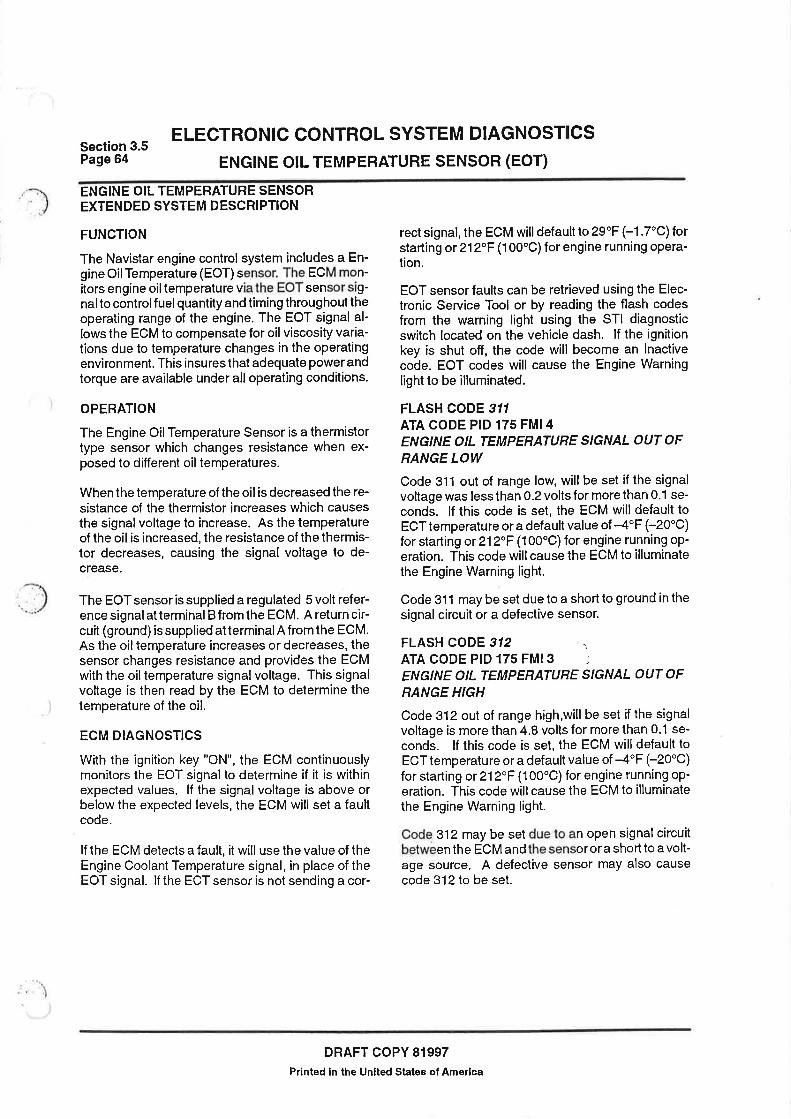
311(1) Engine oil temperature signal out of range: low
Signal voltage less greater 4.8vDefaults to 212 °F (100 °C)No fast idle
Short circuit to earth
312(1) Engine oil temperature signal out of range: high
Signal voltage less than 0.2vDefaults to 212 °F (100 °C)No fast idle
Open circuit
313 Engine oil pressure below warning level Oil warning light on
No oil or low oil level. Faulty regulator . Suction pipe blocked or damaged. Worn main bearings. Worn oil pump.
314 Engine oil pressure below critical level Engine will stop, if this option is fitted
No oil or low oil level. Fault in regulator. Suction pipe blocked or damaged. Worn main bearings. Worn oil pump.
315(1) Engine speed exceeded warning limit
ECM recorded an engine speed greater than 3000 rev/min
Incorrect use of gears in automotive application
316 Engine coolant temp - unable to reach set point
Enabled when only cold ambient protection enabled
Leaking thermostat, cooling system problems
321 Engine coolant temperature above warning level
Coolant temperature greater than 224.6 °F (107 °C) Cooling system fault
322 Engine coolant temperature too high
Coolant temperature greater than 233.6 °F (112,5 °C) Cooling system fault
323 Engine coolant level below warning level ECM finds low coolant level Coolant level low. Leakage of
coolant
324 Idle shutdown timer enabled, engine shutdown
Enabled only when idle shutdown enabled
325 Power reduced to match cooling system performance Engine power reduced High altitude or high ambient
temperature
326 Genset engine speed control fault - -
Flash code Condition description Comments Probable causes
17
Workshop Manual, TPD 1353E, Issue 3 249
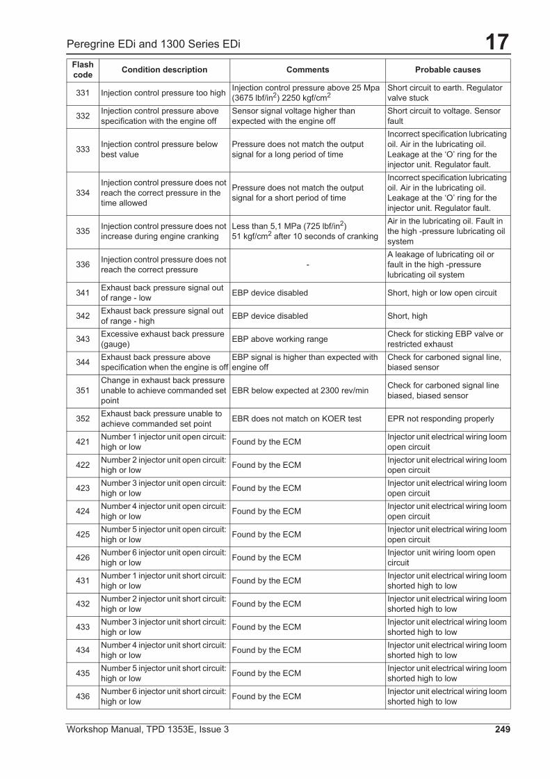
Peregrine EDi and 1300 Series EDi
331 Injection control pressure too high Injection control pressure above 25 Mpa (3675 lbf/in2) 2250 kgf/cm2
Short circuit to earth. Regulator valve stuck
332 Injection control pressure above specification with the engine off
Sensor signal voltage higher than expected with the engine off
Short circuit to voltage. Sensor fault
333 Injection control pressure below best value
Pressure does not match the output signal for a long period of time
Incorrect specification lubricating oil. Air in the lubricating oil. Leakage at the ‘O’ ring for the injector unit. Regulator fault.
334Injection control pressure does not reach the correct pressure in the time allowed
Pressure does not match the output signal for a short period of time
Incorrect specification lubricating oil. Air in the lubricating oil. Leakage at the ‘O’ ring for the injector unit. Regulator fault.
335 Injection control pressure does not increase during engine cranking
Less than 5,1 MPa (725 lbf/in2)51 kgf/cm2 after 10 seconds of cranking
Air in the lubricating oil. Fault in the high -pressure lubricating oil system
336 Injection control pressure does not reach the correct pressure -
A leakage of lubricating oil or fault in the high -pressure lubricating oil system
341 Exhaust back pressure signal out of range - low EBP device disabled Short, high or low open circuit
342 Exhaust back pressure signal out of range - high EBP device disabled Short, high
343 Excessive exhaust back pressure (gauge) EBP above working range Check for sticking EBP valve or
restricted exhaust
344 Exhaust back pressure above specification when the engine is off
EBP signal is higher than expected with engine off
Check for carboned signal line, biased sensor
351Change in exhaust back pressure unable to achieve commanded set point
EBR below expected at 2300 rev/min Check for carboned signal line biased, biased sensor
352 Exhaust back pressure unable to achieve commanded set point EBR does not match on KOER test EPR not responding properly
421 Number 1 injector unit open circuit: high or low Found by the ECM Injector unit electrical wiring loom
open circuit
422 Number 2 injector unit open circuit: high or low Found by the ECM Injector unit electrical wiring loom
open circuit
423 Number 3 injector unit open circuit: high or low Found by the ECM Injector unit electrical wiring loom
open circuit
424 Number 4 injector unit open circuit: high or low Found by the ECM Injector unit electrical wiring loom
open circuit
425 Number 5 injector unit open circuit: high or low Found by the ECM Injector unit electrical wiring loom
open circuit
426 Number 6 injector unit open circuit: high or low Found by the ECM Injector unit wiring loom open
circuit
431 Number 1 injector unit short circuit: high or low Found by the ECM Injector unit electrical wiring loom
shorted high to low
432 Number 2 injector unit short circuit: high or low Found by the ECM Injector unit electrical wiring loom
shorted high to low
433 Number 3 injector unit short circuit: high or low Found by the ECM Injector unit electrical wiring loom
shorted high to low
434 Number 4 injector unit short circuit: high or low Found by the ECM Injector unit electrical wiring loom
shorted high to low
435 Number 5 injector unit short circuit: high or low Found by the ECM Injector unit electrical wiring loom
shorted high to low
436 Number 6 injector unit short circuit: high or low Found by the ECM Injector unit electrical wiring loom
shorted high to low
Flash code Condition description Comments Probable causes
17
250 Workshop Manual, TPD 1353E, Issue 3
Peregrine EDi and 1300 Series EDi
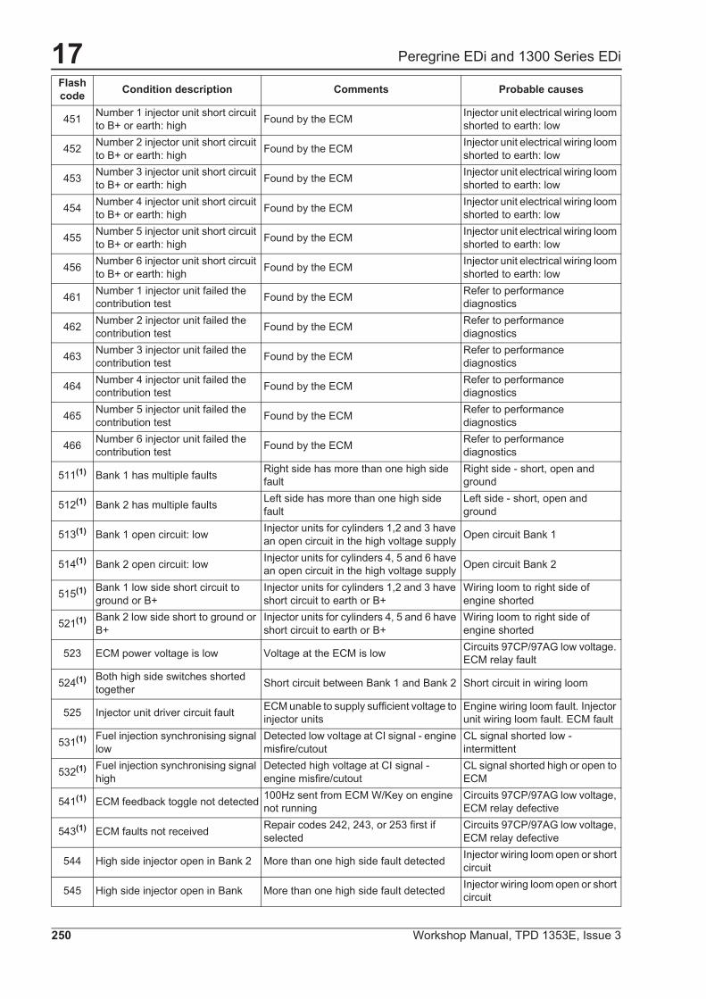
451 Number 1 injector unit short circuit to B+ or earth: high Found by the ECM Injector unit electrical wiring loom
shorted to earth: low
452 Number 2 injector unit short circuit to B+ or earth: high Found by the ECM Injector unit electrical wiring loom
shorted to earth: low
453 Number 3 injector unit short circuit to B+ or earth: high Found by the ECM Injector unit electrical wiring loom
shorted to earth: low
454 Number 4 injector unit short circuit to B+ or earth: high Found by the ECM Injector unit electrical wiring loom
shorted to earth: low
455 Number 5 injector unit short circuit to B+ or earth: high Found by the ECM Injector unit electrical wiring loom
shorted to earth: low
456 Number 6 injector unit short circuit to B+ or earth: high Found by the ECM Injector unit electrical wiring loom
shorted to earth: low
461 Number 1 injector unit failed the contribution test Found by the ECM Refer to performance
diagnostics
462 Number 2 injector unit failed the contribution test Found by the ECM Refer to performance
diagnostics
463 Number 3 injector unit failed the contribution test Found by the ECM Refer to performance
diagnostics
464 Number 4 injector unit failed the contribution test Found by the ECM Refer to performance
diagnostics
465 Number 5 injector unit failed the contribution test Found by the ECM Refer to performance
diagnostics
466 Number 6 injector unit failed the contribution test Found by the ECM Refer to performance
diagnostics
511(1) Bank 1 has multiple faults Right side has more than one high side fault
Right side - short, open and ground
512(1) Bank 2 has multiple faults Left side has more than one high side fault
Left side - short, open and ground
513(1) Bank 1 open circuit: low Injector units for cylinders 1,2 and 3 have an open circuit in the high voltage supply Open circuit Bank 1
514(1) Bank 2 open circuit: low Injector units for cylinders 4, 5 and 6 have an open circuit in the high voltage supply Open circuit Bank 2
515(1) Bank 1 low side short circuit to ground or B+
Injector units for cylinders 1,2 and 3 have short circuit to earth or B+
Wiring loom to right side of engine shorted
521(1) Bank 2 low side short to ground or B+
Injector units for cylinders 4, 5 and 6 have short circuit to earth or B+
Wiring loom to right side of engine shorted
523 ECM power voltage is low Voltage at the ECM is low Circuits 97CP/97AG low voltage. ECM relay fault
524(1) Both high side switches shorted together Short circuit between Bank 1 and Bank 2 Short circuit in wiring loom
525 Injector unit driver circuit fault ECM unable to supply sufficient voltage to injector units
Engine wiring loom fault. Injector unit wiring loom fault. ECM fault
531(1) Fuel injection synchronising signal low
Detected low voltage at CI signal - engine misfire/cutout
CL signal shorted low - intermittent
532(1) Fuel injection synchronising signal high
Detected high voltage at CI signal - engine misfire/cutout
CL signal shorted high or open to ECM
541(1) ECM feedback toggle not detected 100Hz sent from ECM W/Key on engine not running
Circuits 97CP/97AG low voltage, ECM relay defective
543(1) ECM faults not received Repair codes 242, 243, or 253 first if selected
Circuits 97CP/97AG low voltage, ECM relay defective
544 High side injector open in Bank 2 More than one high side fault detected Injector wiring loom open or short circuit
545 High side injector open in Bank More than one high side fault detected Injector wiring loom open or short circuit
Flash code Condition description Comments Probable causes
17
Workshop Manual, TPD 1353E, Issue 3 251
Peregrine EDi and 1300 Series EDi
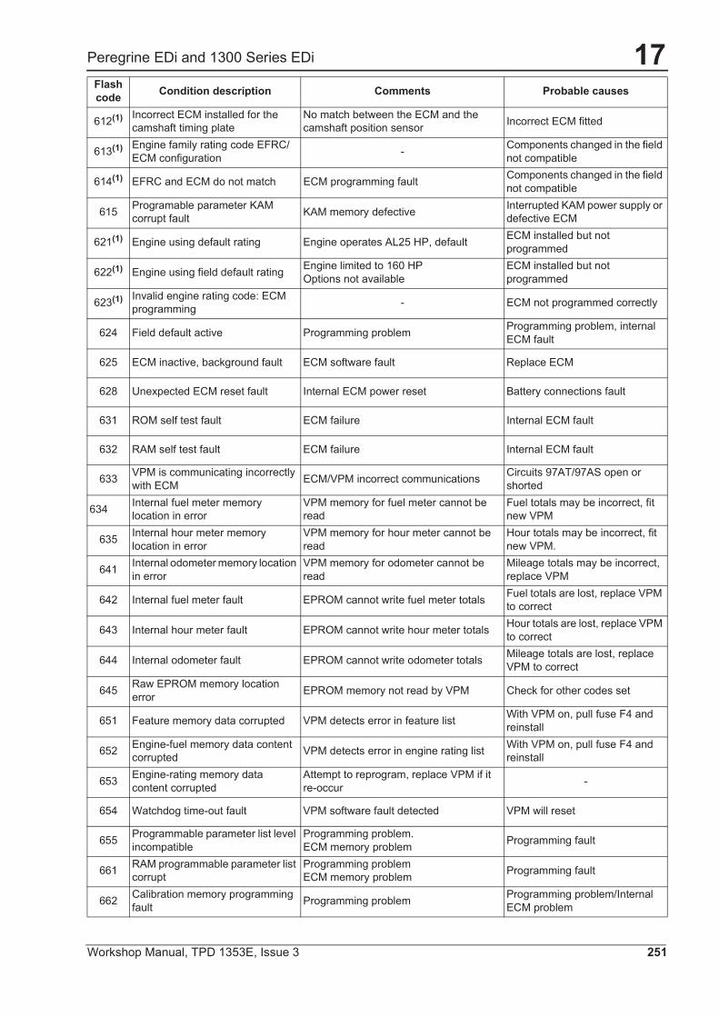
612(1) Incorrect ECM installed for the camshaft timing plate
No match between the ECM and the camshaft position sensor Incorrect ECM fitted
613(1) Engine family rating code EFRC/ECM configuration - Components changed in the field
not compatible
614(1) EFRC and ECM do not match ECM programming fault Components changed in the field not compatible
615 Programable parameter KAM corrupt fault KAM memory defective Interrupted KAM power supply or
defective ECM
621(1) Engine using default rating Engine operates AL25 HP, default ECM installed but not programmed
622(1) Engine using field default rating Engine limited to 160 HPOptions not available
ECM installed but not programmed
623(1) Invalid engine rating code: ECM programming - ECM not programmed correctly
624 Field default active Programming problem Programming problem, internal ECM fault
625 ECM inactive, background fault ECM software fault Replace ECM
628 Unexpected ECM reset fault Internal ECM power reset Battery connections fault
631 ROM self test fault ECM failure Internal ECM fault
632 RAM self test fault ECM failure Internal ECM fault
633 VPM is communicating incorrectly with ECM ECM/VPM incorrect communications Circuits 97AT/97AS open or
shorted
634 Internal fuel meter memory location in error
VPM memory for fuel meter cannot be read
Fuel totals may be incorrect, fit new VPM
635 Internal hour meter memory location in error
VPM memory for hour meter cannot be read
Hour totals may be incorrect, fit new VPM.
641 Internal odometer memory location in error
VPM memory for odometer cannot be read
Mileage totals may be incorrect, replace VPM
642 Internal fuel meter fault EPROM cannot write fuel meter totals Fuel totals are lost, replace VPM to correct
643 Internal hour meter fault EPROM cannot write hour meter totals Hour totals are lost, replace VPM to correct
644 Internal odometer fault EPROM cannot write odometer totals Mileage totals are lost, replace VPM to correct
645 Raw EPROM memory location error EPROM memory not read by VPM Check for other codes set
651 Feature memory data corrupted VPM detects error in feature list With VPM on, pull fuse F4 and reinstall
652 Engine-fuel memory data content corrupted VPM detects error in engine rating list With VPM on, pull fuse F4 and
reinstall
653 Engine-rating memory data content corrupted
Attempt to reprogram, replace VPM if it re-occur -
654 Watchdog time-out fault VPM software fault detected VPM will reset
655 Programmable parameter list level incompatible
Programming problem.ECM memory problem Programming fault
661 RAM programmable parameter list corrupt
Programming problemECM memory problem Programming fault
662 Calibration memory programming fault Programming problem Programming problem/Internal
ECM problem
Flash code Condition description Comments Probable causes
17
252 Workshop Manual, TPD 1353E, Issue 3
Peregrine EDi and 1300 Series EDi
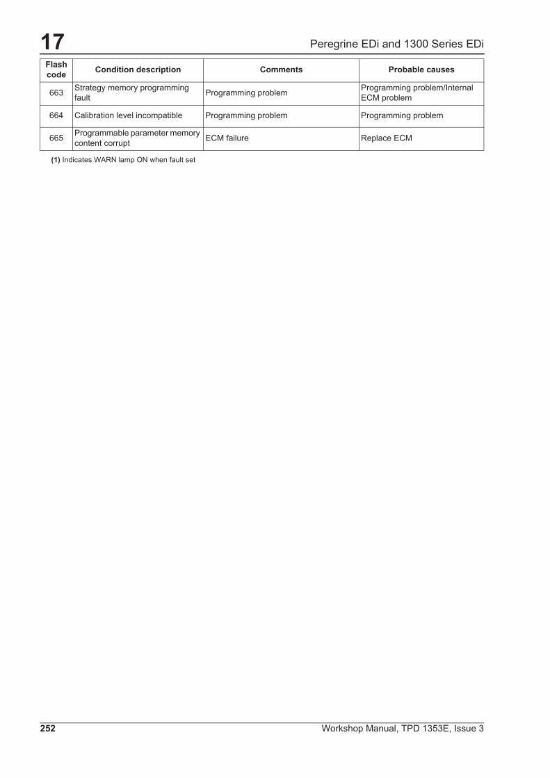
(1) Indicates WARN lamp ON when fault set
663 Strategy memory programming fault Programming problem Programming problem/Internal
ECM problem
664 Calibration level incompatible Programming problem Programming problem
665 Programmable parameter memory content corrupt ECM failure Replace ECM
Flash code Condition description Comments Probable causes


05/05/2009 - PAG. 2 (5)
CODE INDEX
ITALIANO ENGLISH DEUTSCH CODEELETrROMAGNETE PER STARTER STARTER ELECTROMAGNET ELEKTROMAGNET FÜR ANLASSER EMSELETrROVALVOLA SOLENOID VALVE ELEKTROVENTIL EVELETfROVALVOLA BENZINA GASOLINE SOLENOID VALVE BENZIN-ELEKTROVENTIL EVBELETrROVALVOLA GPL LPG SOLENOID VALVE GAS-ELEKTROVENTI EVGFUSIBILE FUSE SICHERUNG FFUSIBILE (02A) FUSE (02A) SICHERUNG (02A) FO2AFUSIBILE (WA) FUSE (10?.) SICHERUNG (1OA) FIOAFUSIBILE(15A) FUSE (15A) SICHERUNG (15A) FI5AFUSIBILE (1A) FUSE (1A) SICHERUNG (1A) FIAFARO ILLUMINAZIONE HEADLIGHT LAMPE FI---F4FUSIBILE (25A) FUSE (25A) SICHERUNG (25A) F25AFUSIBILE (2A) FUSE (2A) SICHERUNG (2A) F2AFUSIBILE (SOA) FUSE (SOA) SICHERUNG (30A) F3OAFUSIBILE (50A) FUSE (50A) SICHERUNG (50A) F5OAFUSIBILE (SA) FUSE (SA) SICHERUNG ( 5A) F5AFUSIBILE (7,5A) FUSE (7,5A) SICHERUNG (7,5A) F75AFUSIBILE (BOA) FUSE (BOA) SICHERUNG (BOA) FBOAFUSIBILE (BA) FUSE (BA) SICHERUNG (BA) F8AGALLEGGIANTE FUEL SENDER SCHWIMMER / TANKGEBER GECM: SPIA ANOMALIA ECM ECM: FAULT-WARNING LIGHTS ECM: ANOMALIE WARNLAMPEN HISPIAANOMALIA FAULT-WARNING LIGHTS ANOMALIEWARNLAMPEN HI I H2ECM: SPIA ANOMALIA ECM ECM: FAULT-WARNING LIGHTS ECM: ANOMALIE WARNLAMPEN H2SPIA PREAWISO DI ALLARME - 1’ STADIO ALARM FOREWARNING LAMP - I STADIUM ALARM VORWARNUNGSLICHT - 1. STADIUM HASPIA ALLARME -2’ STADIO ALARMS LAMP -2’ STADIUM ALARM WARNLICHT -2. STADIUM HAASPIA BATTERIA WARNING LIGHT BAHERY WARNLICHT BAIrERIE HBSPIA CANDELETTE GLOW PLUG WARNING LIGHT WARNLICHT GLUHZEIT HGSPIA DIAGNOSTICA DIAGNOSTIC WARNING LIGHT DIAGNOSE WARNLICHT HDSPIA GENERATORE IN FUNZIONE GENERATOR RUNNING LIGHT WARNLICHT AGGREGAT IN BETRIEB HGSPIA ANOMALIA QUO TEMPERATURA OIL-TEMPERATURE WARNING LIGHT WARNLICHT OLTEMPERATUR HO I HTSPIA RISERVA CARBURANTE FUEL LEVEL WARNING LIGHT WARNLICHT KRAFTSTOFFSTAND IN TANK HRSPIA 5OVRAVELOCITA’ OVER5PEED WARNING LAMP WARNLICHT UBERGESCHWINDIGKEIT HSVFREQUENZIMETRO FREQUENCYMETER FREQUENZMESSER HZINDICATORE LIVELLO CARBURANTE (STRUMENTO) FUEL GAUGE KRAFTSTOFFME55ER ICPULSANTE DI SICUREZZA COPERCHIO APERTO SAFETY SWITCH FOR OPEN DECK SICHERHEITDRUCKSCHALTER FÜR HAUBENDECKEL ICCINSERITORE CANDELETTE / TERMOAWIATORE GLOW-PLUGS INSERTER! THERMOSTARTER GLÜHKERZEN-ANLASSER / THERMOSTARTER ICTINTERRUTrORE DIFFERENZIALE GROUND FAULT INTERRUPTER Fl - SCHALTER IDINVERTITORE DI FASE PHASE INVERSING PHASEN WENDESCHALTER IDFSONDA INTASAMENTO FILTRO ARIA AIR FILTER OBSTRUCTION PROBE LUFTFILTER-VERSCHMUTZUNGS5ONDE IFINTERRUT~ORE ACCENSIONE PUNTO LUCE LAMP SWITCH-ON LAMPEN-SCHALTER IL
-a
05/05/2009 - PAG. 1(5)
CODE INDEX
ITALIANO ENGLISH DEUTSCH CODE
SELETTORE BENZINA(0) - GPL(1) SWITCH SELECTOR GASOLINE(0) - LPG(1) BENZIN (0) - PROPHANGA5 (1) SCHALTER 3B
AMPEROMETRO AMMETER AMPEREMETER A
CIRCUITO ELETTRONICO Dl PROTEZIONE MOTORE ENGINE PROTECTION CIRCUIT ELEKTRONISCHER STROMKREIS FÜR AAOI LC
MOTORSICHERUNGATTUATORE ACTUATOR ACTUATOR ACTU
ALTERNATORE DI RICARICA ENGINE-ALTERNATOR LICHTMASCHINE ALR
REGOLATORE ELET~RONICO (ALTERNATORE) ALTERNATOR ELECTRONIC REGULATOR ELEKTRONISCHER GENERATORREGLER AVR I SR7
I UVR6
BATrERIA BATTERY BATTERIE BA
BLOCCHETTO CHIAVI AWIAMENTO KEYSTARTING SWITCH STARTSCHLOSS (non usare COMMUTATORE DAW.) BC
BOBINA DI SGANCIO SHUNT TRIP UNTERBRECHUNG5SpULE BS
COMMUTATORE DI ESCLUSIONE RELE’ DI SELECTION SWITCH TO EXCLUDE INSULATION HALTEISOLAMENTO MONITORING RELAY SC R FUR ISOLATIONSRELAIS AUSSCHALTUNG C 0-1
CONNETTORI CONNECTIONS ANSCHLUSSE Cl CN
CARICA BATTERIA BATTERY CHARGER BATTERIELADEGERAT CB
ECM: CONNETrORE DIAGNOSTICA ECM: DIAGNOSTIC CONNECTOR ECM: DIAGNOSE-ANSCHLU5S CD
COMMUTATORE DI VOLTAGGIO PHASE SELECTION SWITCH PHASEN-UMWANDLER CDV
CONNETrORE “EASY LINK’ ‘EASY LINK” CONNECTION “EASY LINK” ANSCHLUSS CEL
CONTROLLO DELL UNITN D’ INTERFACCIA CONTROL INTERFACE UNIT KONTROLLE DER SCHNITTSTELLE-EINHEIT CIU
COMMUTATORE MOTORIZZATO “ SOCOMEC” CHANGEOVER SWITCH” SOCOMEC” “ SOCOMEC “MOTORISIERTER UMWANDLER CMS
CONTAORE HOURMETER BETRIEBSSTUNDENZAHLER CO
CANDELETTE DI PRERISCALDO PRE-HEATER GLOW PLUG VORWARMUNGSGLCJHKERZEN CP
COMMUTATORE VOLTMETRICO VOLTMETER SELECTION SWITCH SPANNUNGSANZEIGER-UMWANDLER CV
DIODO / COPIIA DIODI DIODE / DIODES SET DIODE / DIODENSATZ D
DISPOSITIVO DI ANTICIPO AWIO A FREDDO COLD START ADVANCE KALT-START VORSCHUSS DA
RELE DIFFERENZIALE (TE 802) DIFFERENTIAL RELAY FI-RELAIS DeTta4RELE’ DIFFERENZIALE (Z804) DIFFERENTIAL RELAY FI-RELAIS DER2RELE’ VOLTMETRICO TRIFASE DI MIN-MAX TENSIONE THREE-PHASE MIN-MAX VOLTAGE CONTROL RELAY DREIPHASIGER UNTER-UND DRV3
ÜBERSPANNUNGSWACHTERECM: CETRALINA ELETTRONICA DI GESTIONE ECM: ELECTRONIC BOX FOR PERKINS ENGINE- ECM: ELEKTRONIK FÜR PERKINS-MOTOR5TEUERUNG ECMMOTORE PERKINS MANAGMENTEDC: CENTRALINA ELETTRONICA DI GESTIONE EDC: ELECTRONIC BOX FOR ENGINE-MANAGMENT EDC: ELEKTRONIK FÜR MOTORSTEUERUNG (VOLVO - EDCMOTORE (VOLVO - IVECO) (VOLVO- IVECO) IVECO)EDC: CENTRALINA ELETTRONICA DI GESTIONE EDC: ELECTRONIC BOX FOR IVECO ENGINE- EDC: ELEKTRONIK FÜR IVECO-MOTORSTEUERUNG EDCMOTORE IVECO MANAGMENTELETTROVALVOLA FLUSSO CARBURANTE FUEL FILL UP SOLENOID VALVE KRAFTSTOFF-UMFULLUNGSLLEKTROVENTIL EFCELEmROMAGNETE DI STOP STOP ELECTROMAGNET STOP-MAGNET EMEMR: CETRALINA ELETrRONICA DI GESTIONE ELECTRONIC BOX FOR DEUTZ ENGINE-MANAGMENT ELEKTRONIK FÜR DEUTZ-MOTORSTEUERIJNG EMRMOTORE DEUTZ
05105/2009 - PAG. 3 (5)
CODE INDEX
ITALIANO ENGLISH DEUTSCH CODE
INTERRUTTORE MAGNETOTERMICO CIRCUIT BREAKER LEITUNGSSCHUTZSCHALTER IM I 1M2INTERRUTrORE MAGNETOTERMICO COMPRESSORE COMPRESSOR CIRCUIT BREAKER KOMPRE5SOR LEITUNG55CHUTZ5CHALTER IMCINTERRUTORE MAGNETOTERMICO DIFFERENZIALE RESIDUAL CURRENT CIRCUIT BREAKERS WITH FEHLERSTROM - LEITUNGSSCHUTZSCHALTER IMD
INTEGRAL OVERCURRENT PROTECTION (RCBO)INTERRUTTORE MAGNETOTERMICO FARI HEADLIGHTS CIRCUIT BREAKER LAMPEN LEITUNGSSCHUTZSCHALTER IMFI-IMF4INDICATORE PRE55IONE OLIO (STRUMENTO) OIL PRESSURE GAUGE OLDRUCKMESSER IPINTERRUTrORE SCALDIGLIA HEATER SWITCH HEIZGERAT-SCHALTER IRINDICATORE DI TEMPERATURA (STRUMENTO) TEMPERATURE GAUGE TEMPERATURMESSER IT
RELE ACCENSIONE GAS GAS IGNITION RELAY GAS-ZONDRELAI5 KAGRELE’ RELAY RELAIS KAVRELE’ PER BOBINA DI SGANCIO SHUNT TRIP RELAY RELAIS FÜR UNTERBRECHUNG55PULE KBSRELE DIFFERENZIALE EARTH-LEAKAGE RELAY FI-RELAIS KDFRELE ELETrROVALVQLA GAS GAS SOLENOID VALVE RELAY GAS ELEKTROVENTIL RELAIS KEVGRELE’ MIN - MAX GIRl MOTORE ENGINE SPEED MIN. - MAX. RELAY MINJMAX MOTORDREHZAHL RELAIS KGMRELE PER LAWIAMENTO STARTING RELAY ANLASSER-RELAIS KMRELE DI PRERISCALDO CANDELETTA RELAY OF PRE-HEATING GLOW PLUG RELAIS FÜR GLUHKERZEN -VORWARMUNG KRRELE RISCALDATORE FILTRO COMBUSTIBILE HEATER RELAY FOR FUEL FILTER WARMER RELAIS FÜR KRAFTSTOFF-FILTER KRCCENTRALINA PRERISCALDO CANDELETrE GLOW CARD VORWARMUNGS-EINHEIT KRGRELE’ LIVELLO OLIO COMBUSTIBILE OIL FUEL LEVEL RELAY KRAFTSTOFFNIVEAUX RELAY (OL) KROCRELE VOLTMETRICO VOLTMETER RELAY VOLTMETER RELAIS KVCONTATORE UTIF POWER-COUNTER STROMZAHLER KWHRELE’ DI STOP STOP RELAY ABSCHALT - RELAIS KYLAMPADA SPIA WARNING LIGHT WARNLAMPE LSONDA LIVELLO CARBURANTE FUEL-LEVEL PROBE KRAFTSTOFFSTANDANZEIGER-SONDE LCLIMITATORE DI FUMO IN AWIAMENTO START SMOKE LIMITER RAUCHBESCHRANKER IM ANTRIEB LFMORSETFIERA TORRE ILLUMINAZIONE LIGHTING TOWER TERMINAL BOX LICHTMAST KLEMMKASTEN LTMOTORINO D’AWIAMENTO STARTING ENGINE STARTERMOTOR (OPPURE ANLASSER) MAMORSETrIERA TERMINAL CONNECTIONS KLEMMBRETT MCMOTORE DEL COMPRESSORE (x torre ilium.) COMPRESSORS ENGINE ( for lighting tower) KOMPRESSOR-MOTOR (fur Lichtmast) MCOECM: CONNESSIONI PER MODULO ECM: CONNECTIONS ECM: ANSCHLUSSE MECMEDC: CONNESSIONI PER MODULO EDC: CONNECTIONS EDC: ANSCHLUSSE MEDCMORSETTIERA ALTERNATORE ALTERNATOR TERMINAL CONNECTIONS GENERATOR KLEMMBRETT MGRESISTENZE PER VARIAZIONE GIRl MOTORE (50/ RESISTANCE FOR RPM CHANGE WIDERSTANDSMODUL/MOMENT MRHz)MOTORE ROTAZIONE FARI ENGINE FOR LIGHTS ROTATION MOTOR FUR LAMPEN-UMDREHUNG MRFMOTORE ELEITRICO PER VENTOLA RADIATORE ELECTRIC ENGINE FOR RADIATOR FAN ELEKTRISCHER MOTOR FUR KUHLERLUFTER MVNEUTRO NEUTRAL ( WIRE) NULL-LEITER NECM: PULSANTE ALIMENTAZIONE MANUALE ECM: MANUAL POWER PUSH BUTTON ECM: HANDZUFOHRUNG-DRUCKTASTE PAE
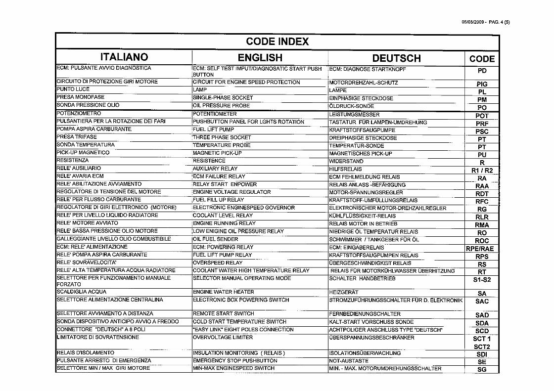
05/05/2009 - PAG. 4 (5)
CODE INDEX
ITALIANO ENGLISH DEUTSCH CODE
ECM: PULSANTE AWIO DIAGNOSTICA ECM: SELF TEST IMPUT/DIAGNOSATIC START PUSH ECM: DIAGNOSE STARTKNOPF PDBUTTON
CIRCUITO DI PROTEZIONE GIRl MOTORE CIRCUIT FOR ENGINE SPEED PROTECTION MOTORDREHZAHL-SCHUTZ PIGPUNTO LUCE LAMP LAMPE PLPRESA MONOFASE SINGLE-PHASE SOCKET EINPHASIGE STECKDOSE PMSONDA PRESSIONE OLIO OIL PRESSURE PROBE OLDRUCK-SONDE P0POTENZIOMETRO POTENTIOMETER LEISTUNGSMESSER POTPULSANTIERA PER LA ROTAZIONE DEl FARI PUSHBUTTON PANEL FOR LGHTS ROTATION TASTATUR FÜR LAMPEN-UMDREHUNc3 PRFPOMPAASPIRACARBURANTE FUEL LIFT PUMP KRAFTSTOFF5AUGPUMPE p5iPRESA TRIFASE THREE PHASE SOCKET DREIPHASIGE STECKDOSE PTSONDA TEMPERATURA TEMPERATURE PROBE TEMPERATUR-SONDE PTPICK-UP MAGNETICO MAGNETIC PICK-UP MAGNETISCHES PICK-UP pIJRESISTENZA RESISTENCE WIDERSTAND RRELE AUSILIARIO AUXILIARY RELAY HILFSRELAIS RI I R2RELE’ AVARIA ECM ECM FAILURE RELAY ECM FEHLMELDUNG RELAIS pARELE’ ABILITAZIONE AWIAMENTO RELAY START ENPOWER RELAIS ANLASS -BEFAHIGUNG RAAREGOLATORE DI TENSIONE DEL MOTORE ENGINE VOLTAGE REGULATOR MOTOR-SPANNUNGSREGLER - RDTRELE PER FLUSSO CARBURANTE FUEL FILL UP RELAY KRAFTSTOFF-UMFULLUNGSRELAIS RFCREGOLATORE DI GIRl ELETTRONICO (MOTORE) ELECTRONIC ENGINESPEED GOVERNOR ELEKTRONISCHER MOTOR-DREHZAHLREGLER RGRELE’ PER LIVELLO LIQUIDO RADIATORE COOLANT LEVEL RELAY KCJHLFLUSSIGKEIT-RELAI5 RLRRELE MOTOREAWIATO ENGINE RUNNING RELAY RELAIS MOTOR IN BETRIEB RMARELE BASSA PRESSIONE OLIO MOTORE LOW ENIGINE OIL PRESSURE RELAY NIEDRIGE OL TEMPERATUR RELAIS ROGALLEGGIANTE LIVELLO OLIO COMBUSTIBILE OIL FUEL SENDER SCHWIMMER / TANKGEBER FÜR OL ROCECM: RELE’ ALIMENTAZIONE ECM: POWERING RELAY ECM: EINGABERELAIS RPEIRAERELE’ POMPAASPIRACARBURANTE FUEL LIFT PUMP RELAY KRAFTSTOFFSAUGPUMPEN RELAIS RPSRELE SOVRAVELOCITA’ OVERSPEED RELAY UBERGESCHWINDIGKEIT RELAIS RSRELE ALTA TEMPERATURA ACQUA RADIATORE COOLANT WATER HIGH TEMPERATURE RELAY RELAIS FÜR MOTORKOHLWASSER UBERHITzUNG RTSELETTORE PER FUNZIONAMENTO MANUALE SELECTOR MANUAL OPERATING MODE SCHALTER HANDBETRIEB SI -52FORZATOSCALDIGLIA ACQUA ENGINE WATER HEATER HEIZGERAT SASELETTORE ALIMENTAZIONE CENTRALINA ELECTRONIC BOX POWERING SWITCH STROMZUFQHRUNGSSCHALTER FÜR D. ELEKTRONIK SAC
SELETrORE AWIAMENTO A DISTANZA REMOTE START SWITCH FERNBEDIENUNGSCHALTER SADSONDA DISPOSITIVO ANTICIPO AWIO A FREDDO COLD START TEMPERATURE SWITCH KALT-START VORSCHUSS SONDE SDACONNETTORE “DEUTSCHM AS POLl “EASY LINK” EIGHT POLES CONNECTION ACHTPOLIGER ANSCHLUSS TYPE wDEUTSCH SCDLIMITATORE DI SOVRATENSIONE OVERVOLTAGE LIMITER UBERSPANNUNGSBESCHRANKER SCT I
SCT2RELAIS DISOLAMENTO INSULATION MONITORING ( RELAIS) ISOLATIONSÜBERWACHUNG SDIPULSANTE ARRESTO DI EMERGENZA EMERGENCY STOP PUSHBUTTON NOT-AUSTASTE SESELETTORE MIN / MAX GIRl MOTORE MIN-MAX ENGINESPEED SWITCH MIN. - MAX. MOTORUMDREHUNGSSCHALTER SG
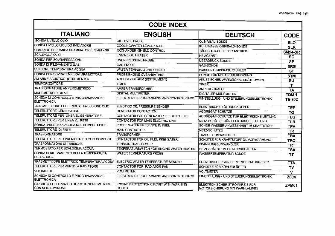
05/05/2009- PAG. 5(5)
CODE INDEXITALIANO ENGLISH DEUTSCH CODE
SONDA LIVELLO OLIO OIL LEVEL PROBE OL NIVEAU SONDE SLOSONDA LIVELLO LIQUIDO RADIATORE COOLINGWATER-LEVELPROBE KÜHLWASSER-NIVEAUX-SONDE SLRCOMANDO SERRANDA SCAMBIATORE SM24 - SR EXCHANGER -SHIELD CONTROL TAUSCHER-SCHIEBER ANTRIEB SM24-SRSCALDIGLIA OLIO ENGINE OIL HEATER HEIZGERAT soSONDA PER SOVRAPRESSIONE OVERPRESSURE PROBE UBERDRUCK SONDE
SONDA DI RILEVAMENTO GAS GAS PROBE GAS-SONDE SRGSENSORE TEMPERATURA ACQUA WATER TEMPERATURE FEELER WASSERTEMPERATURFUF-iLER STSONDA PER SOVRATEMPERATURA MOTORE PROBE ENGINE OVERHEATING SONDE FÜR MOTORQBERHITZUNG STMALLARME ACUSTICO (STRUMENTO) ACOUSTIC ALARM (INSTRUMENT) AKUSTISCHES WARNSIGNAL (INSTRUMENT) SuTEMPORIZZATORE TIMER TIMER TTRASFORMATORE AMPEROMETRICO AMPER-TRAN5FORMER AMPERE-TRAFO TAMULTIMETRO DIGITALE DIGITAL MULTIMETER DIGITALER MULTIMETER TDM ISCHEDA DI CONTROLLO E PROGRAMMAZIONE ELECTRONIC PROGRAMMING AND CONTROL CARD EINSTELLUNG.- UND STEUERUNGSELEKTRONIK TE 802ELETTRONICATRASMETflTORE ELETTRICO DI PRESSIONE OLIO ELECTRIC OIL PRESSURE SENDER ELEKTRISCHER OLDRUCKGEBER TEPTELERUTTORE GENERATORE GENERATOR CONTACTOR AGGREGAT-SCHUTZE TGTELERUTTORE PER LINEA EL.GENERATORE CONTACTOR FOR GENERATOR ELECTRIC LINE AGGREGAT-SCHOTZE FÜR ELEKTRISCHE LEITUNG TLG —
TELERUTTORE PER LINEA EL. RETE CONTACTOR FOR MAIN ELECTRIC LINE NETZ-SCHUTZE GOR ELEKTRISCHE LEITUNG TLRSONDA PRESENZA ACQUA NEL COMBUSTIBILE PROBE WATER PRESENCE IN FUEL SONDE WASSER-ANWESENHEIT IM KRAFTSTOFF TPATELERUTTORE DI RETE MAIN CONTACTOR NETZ-SCHUTZE TRTRASFORMATORE TRANSFORMER TRAFO I UMWANDLER TRATELERUTTORE PER PRERI5CALDO OLIO COMBUST. CONTACTOR FOR OIL FUEL PREHEATER SCHQTZE FÜR KRAFTSTOFF-OL VORWARMUNG TROTRASFORMATORE DI TENSIONE TENSION TRASFORMER SPANNUNGSUMWANDLER TRTTERMOSTATO PER SCALDIGLIAACQUA TEMPERATURSWITCH FOR ENGINE WATER HEATER HEIZGERATSTEMPERATURSCHALTER TSASONDA DI RILEVAMENTO DELLA TEMPERATURA WATER TEMPERATURE PROBE WASSERTEMPERATUR-SONDE TTDELL’ACQUATRASMETTITORE ELETTRICO TEMPERATURA ACQUA ELECTRIC WATER TEMPERATURE SENDER ELEKTRISCHER WASSERTEMPERATURGEBER TTATELERUTrORE PER VENTOLA RADIATORE CONTACTOR FOR RADIATOR-FAN SCHUTZE FÜR KUHLERLUFTER TVVOLTMETRO VOLTMETER VOLTMETER VSCHEDA DI CONTROLLO E PROGRAMMAZIONE ELECTRONIC PROGRAMMING AND CONTROL CARD EINSTELLUNG.- UND STEUERUNGSELEKTRONIK Z804ELETrRONICACIRCUITO ELETTRONICO DI PROTEZIONE MOTORE ENGINE PROTECTION CIRCUIT WITH WARNING ELEKTRONISCHER STROMKREIS FÜR ZPMOICON SPIE LUMINOSE LIGHTS MOTORSICHERUNG MIT WARNLAMPEN