performance modelsperformance models - arctic cat · ’s manual cfr 800 cfr 1000 f5 lxr f570 f6...
TRANSCRIPT

Operato
r’s
Manual
CFR 800CFR 1000F5 LXRF570F6 Sno ProF8 EXT/LXR/Sno Pro/LTDZ1/LXR/Sno ProZ1 Turbo/EXT/LXR/Sno Pro/LTD
Performance ModelsPerformance Models
SHARE OUR PASSION.TM
2011
Limited Warranty Arctic Cat Inc. (hereinafter referred to as Arctic Cat) extends a limited warranty on each new Arctic CatSnowmobile it assembles and on each part and accessory assembled or sold by Arctic Cat. Thewarranty is extended to the original retail purchaser only on parts and accessories sold through anauthorized Arctic Cat Snowmobile dealer. Warranty on snowmobiles is extended to the original retailpurchaser; however, the balance of the unused warranty may be transferred to another party. Warrantycoverage is only available in the country in which the original retail purchase occurs to the original retailpurchaser resident in that country or to a transferee resident in that country of the balance of the unusedwarranty.
Arctic Cat warrants only the products it assembles and/or sells and does not warrant that other productswill function properly when used with an Arctic Cat Snowmobile or will not damage the Arctic CatSnowmobile. Arctic Cat does not assume any liability for incidental or consequential damages.
Arctic Cat will repair or replace, at its option, free of charge (including any related labor charges), anyparts that are found to be warrantable in material or workmanship. This repair work MUST be done by anauthorized Arctic Cat Snowmobile dealer. No transportation charges, rental charges, or inconveniencecosts will be paid by Arctic Cat. The warranty is validated upon examination of said parts by Arctic Cat oran authorized Arctic Cat Snowmobile dealer. Arctic Cat reserves the right to inspect such parts at itsfactory for final determination if warranty should apply.
The warranty periods are as follows:
1. For snowmobiles used for recreational purposes:—If purchased between May 1 and November 30, warranty expires ONE (1) YEAR from December1 of the current year.—If purchased between December 1 and April 30, ONE (1) YEAR from the date of sale.
2. For snowmobiles used for commercial purposes (including rental operations), ONE (1) YEAR fromthe date of invoice and/or 5000 MILES whichever comes first (non-transferable).
3. THIRTY (30) DAYS from date of sale of snowmobile on Arctic Cat supplied batteries.4. THIRTY (30) DAYS from date of sale for all dealer installed genuine Arctic Cat service parts and
accessories.5. UNTIL EXPIRATION OF THE NEW PRODUCT WARRANTY (paragraphs 1 and 2 above) for all
eligible replacement parts on new product.Exclusions to this warranty include normal wear, abuse (i.e. a track run on marginal snowconditions without proper lubrication or additional idler wheels), and the following parts:
Fuel Filter Light Bulbs Windshield Torn or Punctured UpholsteryDrive Belt Wear Bars Water Pump Belt Brake PadsFan Belt Spark Plugs Wear Strips Drive Clutch/Driven Pulley Wear Parts
The following will VOID Arctic Cat’s warranty:
1. Failure to perform the proper break-in procedure and all related maintenance, storage procedures (ifstored for extended periods), and/or service as recommended in the Operator’s Manual.
2. Repairs and/or adjustments by anyone other than an authorized Arctic Cat Snowmobile dealer.3. Use of an improper fuel mixture ratio.4. Use of improper carburetor main jets.5. Use of improper gasoline, lubricating oils, or spark plugs.6. An accident or subjecting the snowmobile to misuse, abuse, or negligent operation.7. Any modification, addition, or removal of parts unless instructed to do so by Arctic Cat.8. Use of the snowmobile in any way for racing purposes.9. Removal of the engine for use in another vehicle.
10. Removal or mutilation of the Vehicle Identification Number or Engine Serial Number.11. Use of parts not sold or approved by Arctic Cat.12. Track and tunnel damage resulting from either ice stud or hooker plate installation.13. Damage due to improper transportation.In consideration of the foregoing, any implied warranty is limited in duration to the various warrantyperiods set forth. This warranty gives you specific legal rights, and you may also have other rights whichvary from state/province to state/province and country to country. Some jurisdictions do not allowlimitations on how long an implied warranty lasts, so the above limitations may not apply to you.
Table of ContentsLimited Warranty........................ Inside Front CoverForeword............................................................... 1Declaration of Conformity ..................................... 2Snowmobile Safety Rules ..................................... 3General Information ......................................... 4-23Snowmobile Identification ....................................... 4Control Locations.................................................... 4Gasoline-Oil ............................................................ 5Engine Break-In ...................................................... 6Drive Belt Break-In.................................................. 7Cold Drive-Away Function (Z1/Z1 Turbo Models) ... 7Speedometer/Tachometer ...................................... 8Diagnostic Codes.................................................. 13Handlebar Tilt ....................................................... 14Exhaust System.................................................... 15Air-Intake Silencer ................................................ 15Cooling System (CFR/F5/F6/F8/Z1/Z1 Turbo Models) ............................................................... 16
Battery (Electric Start) .......................................... 16Jump-Starting (Z1/Z1 Turbo Models) .................... 16Drive Clutch and Driven Pulley ............................. 17Drive Clutch/Driven Pulley Alignment ................... 18Fuel Pump ............................................................ 18Shock Absorbers .................................................. 18Standard-Lug Track .............................................. 19Deep-Lug Track .................................................... 19Track Studs ........................................................... 19Reverse Operation................................................ 20Towing................................................................... 21Removable/Adjustable Seat (F5/F6/F8/Z1 LXR/Z1 Turbo Models) ................................................ 21
Arctic Power Valve (APV) System (CFR/F6/F8 Models) ............................................................... 22
Exhaust Controlled Timing (ECT) System (CFR/F6/F8 Models) ........................................... 23
Operating Instructions.................................... 24-29Starting and Stopping Engine............................... 24Braking.................................................................. 26Emergency Stopping ............................................ 27Throttle/Ignition Monitor Switch ............................ 27Varying Altitude Operation.................................... 29
Lubrication ..................................................... 30-33ACT Drive Gear Case ...........................................30Front Suspension ..................................................32Rear Suspension...................................................32
Maintenance .................................................. 34-60Periodic Maintenance Checklist ............................34Air Cleaner/Filter (Z1 Turbo Models) .....................35Fuel System ..........................................................35Checking Engine Oil Level (Z1/Z1 Turbo Models) ..........................................37
Changing Engine Oil/Filter (Z1/Z1 Turbo Models) ..........................................37
Coolant Level ........................................................38Adjusting/Calibrating Carburetors (F570 Model) ...39Spark Plugs...........................................................42Checking/Adjusting Valve Clearance (Z1/Z1 Turbo Models) ..........................................44
Checking/Adjusting APV Cables (CFR/F6/F8 Models)................................................................44
Battery (Electric Start)...........................................45Fuses ....................................................................47Brake System........................................................48Drive Belt...............................................................50Track Tension ........................................................52Track Alignment.....................................................53Suspension ...........................................................54Lights.....................................................................57Ski Wear Bars .......................................................59Adjusting Ski Stance (CFR Models)......................60Rail Wear Strips ....................................................60
Performance Tips........................................... 61-63Preparation for Storage.................................. 64-65Preparation after Storage.................................... 66U.S. EPA Emission Control Statement/Warranty
Coverage (U.S. Only) ...................................... 68Change of Address, Ownership, or Warranty
Transfer............................................................ 69Warranty Procedure/Owner
Responsibility ......................... Inside Back Cover
Reference InformationWrite the appropriate information for your Arctic Cat Snowmobile in the spacesbelow.
Always use these numbers when referring to your snowmobile.
Model: _________________________________________________Date of Purchase: ________________________________________Vehicle Identification Number: _______________________________Engine Serial Number: _____________________________________Your Arctic Cat Dealer: ___________________________________Address: _______________________________________________Phone: _________________________________________________
! WARNINGA snowmobile is a very high performance vehicle. Because it does acceler-ate rapidly and is capable of very high speeds, it should not be operated by anovice or an inexperienced operator. Never accelerate rapidly or drive athigh speed beyond the limits of visibility or without being totally familiarwith the terrain and what lies in front of you. Obey speed limits and neveroperate at speeds that do not allow adequate maneuvering and stopping dis-tances. Read and study the entire Operator’s Manual and Safety Handbook.Failure to follow this warning could result in personal injury to yourself orothers.
Personal Injury• To avoid injury to yourself and others, NEVER operate the snowmobile without
first reading and understanding this manual and the Snowmobile Safety Hand-book; then follow the instructions and heed the warnings given.
• USE COMMON SENSE.• DON’T DRINK and DRIVE.• STAY IN CONTROL at ALL TIMES.• TELL YOUR FRIENDS. If you see a friend operating a snowmobile recklessly, at
excessive speeds, while intoxicated, or in other unsafe ways, don’t wait until it istoo late to warn of the consequences of snowmobile misuse. Such conductendangers everyone. TAKE AN ACTIVE ROLE IN THE SAFETY OF YOUR-SELF AND OTHERS.
Parts and AccessoriesWhen in need of replacement parts, oil, or accessories for your Arctic Cat Snowmo-bile, be sure to only use GENUINE ARCTIC CAT PARTS, OIL, AND ACCESSO-RIES. Only genuine Arctic Cat parts, oil, and accessories are engineered to meet thestandards and requirements of your Arctic Cat Snowmobile. For a complete list ofaccessories, refer to the current Arctic Cat Accessory Catalog. To aid in service andmaintenance procedures on these snowmobiles, an Illustrated Parts Manual and aService Manual are available through your local Arctic Cat Snowmobile dealer.

1
ForewordCongratulations! You have chosen a quality Arctic Cat Snowmobile designed andassembled to give dependable service. Be sure, as the owner/operator of an ArcticCat Snowmobile, to become thoroughly familiar with its basic operation, mainte-nance, and off-season storage procedures. Read this manual and the accompanyingSnowmobile Safety Handbook before operating the snowmobile to learn safe andproper use of your new Arctic Cat Snowmobile. Always operate the snowmobilewithin your level of skill and current terrain conditions.
The Operator’s Manual, Snowmobile Safety Handbook, and Snowmobile Decalsdisplay the words Warning, Caution, and Note to emphasize important information.The symbol ! WARNING identifies personal safety-related information. Besure to follow the directive because it deals with the possibility of serious personalinjury or even death. A CAUTION identifies unsafe practices which may resultin snowmobile-related damage. Follow the directive because it deals with the possi-bility of damaging part or parts of the snowmobile. The symbol NOTE: identi-fies supplementary information worthy of particular attention.
This manual covers operator-related maintenance, operating instructions, and off-season storage instructions. If major repair or service is ever required, contact anauthorized Arctic Cat Snowmobile dealer for professional service.
At the time of publication, all information and illustrations were technically cor-rect. Some illustrations used in this manual are used for clarity purposes only andare not designed to depict actual conditions. Because Arctic Cat Inc. constantlyrefines and improves its products, no retroactive obligation is incurred.
This Operator’s Manual should be considered a permanent part of the snowmobileand must remain with the snowmobile at the time of resale. If the snowmobilechanges ownership more than once, contact Arctic Cat Inc., Service Department,P.O. Box 810, Thief River Falls, MN 56701, for proper registration information.This manual was prepared by the Product Service and Warranty Department ofArctic Cat Inc.
Every Arctic Cat Snowmobile meets or exceeds the standards of the SnowmobileSafety and Certification Committee and displays the SSCC decal. Arctic Cat Inc.endorses and encourages the safe use of all snowmobiles. Always wear a helmetand eye protection. Drive with caution, observe all state and local regulations, andrespect the rights of others. ISMA members like Arctic Cat do their part to improvetrails, sponsor events, and generally support the sport of snowmobiling. As a mem-ber of the National Snowmobile Foundation, Arctic Cat Inc. promotes snowmobil-ing through education, charity, and research programs.
© 2010 Arctic Cat Inc.
Printed in U.S.A.

2
Declaration of ConformityApplication of council directives:Issued by European Commission.
EMC Directive 89/336/EECEC Machinery Directive 98/37/EC
Type of Equipment: SnowmobileBrand Name: Arctic CatModel Numbers:
S2011Z1NEBUSG S2011Z1NLPUSG S2011F5DFCUSG S2011F5CLXUSG
S2011F6DEPUSG S2011F8HXEUSG S2011F8HLXUSG S2011F8HEPUSG
S2011F8HLEUSG S2011CFHRCUSW S2011Z1NTPUSO S2011CFLRCUSW
S2011Z1NTSUSG S2011Z1NLXUSG S2011Z1NLXUSO S2011Z1NTSUSO
S2011Z1NTXUSG S2011Z1NTPUSG S2011F5DFCUSO S2011F5CLXUSO
S2011F6DEPUSO S2011F8HEPUSO S2011F8HLXUSO S2011Z1NLPUSO
Standards to which conformity is declared:EMC:MACHINERY:
EN 55012, EN 61000-6-0EN 292-1, EN 292-2, EN 953, EN 1050, EN 954-1
Manufacturer (if not issuing agent): Arctic Cat Inc.601 Brooks Ave. S.Thief River Falls, MN56701 USA

3
Snowmobile Safety Rules
4
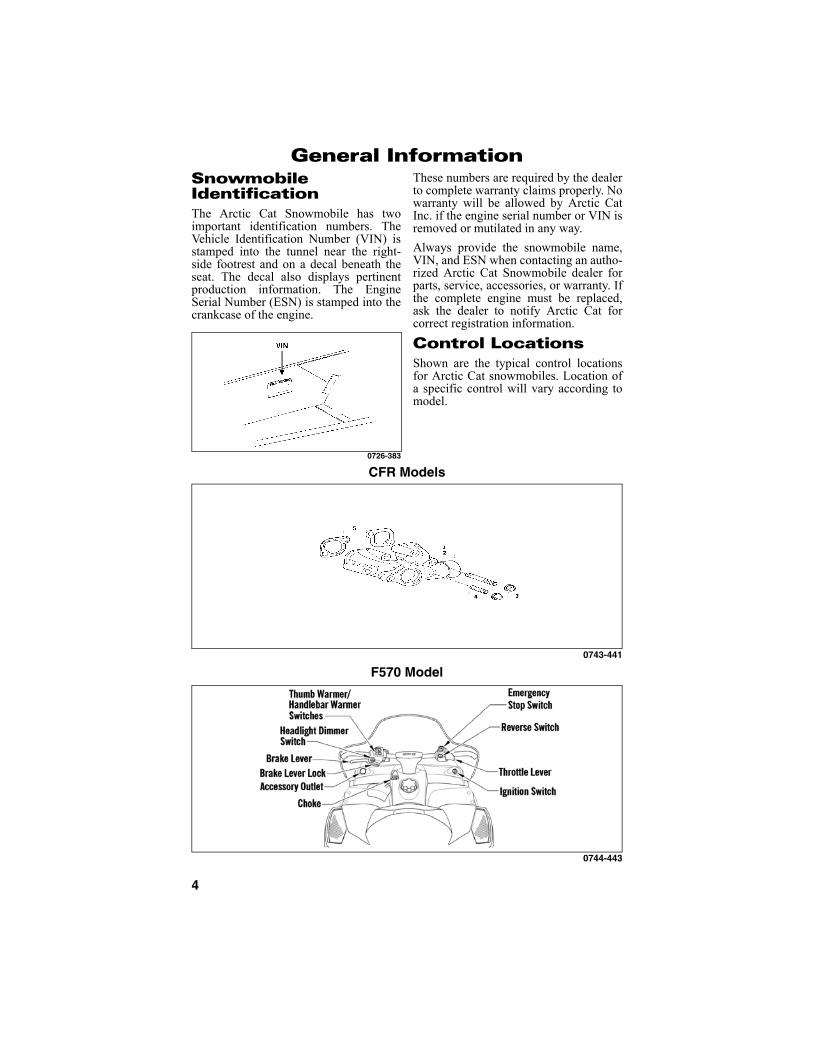
General InformationSnowmobile IdentificationThe Arctic Cat Snowmobile has twoimportant identification numbers. TheVehicle Identification Number (VIN) isstamped into the tunnel near the right-side footrest and on a decal beneath theseat. The decal also displays pertinentproduction information. The EngineSerial Number (ESN) is stamped into thecrankcase of the engine.
0726-383
These numbers are required by the dealerto complete warranty claims properly. Nowarranty will be allowed by Arctic CatInc. if the engine serial number or VIN isremoved or mutilated in any way.
Always provide the snowmobile name,VIN, and ESN when contacting an autho-rized Arctic Cat Snowmobile dealer forparts, service, accessories, or warranty. Ifthe complete engine must be replaced,ask the dealer to notify Arctic Cat forcorrect registration information.
Control LocationsShown are the typical control locationsfor Arctic Cat snowmobiles. Location ofa specific control will vary according tomodel.
CFR Models
0743-441
F570 Model
0744-443

5
F5/F6/F8/Z1/Z1 Turbo Models
0745-213
Gasoline-OilRecommended Gasoline (CFR 1000/F5/F570/F6/Z1/Z1 Turbo Models)
The recommended gasoline to use inthese snowmobiles is 87 octane regularunleaded. In many areas, oxygenates(either ethanol or MTBE) are added tothe gasoline. Oxygenated gasolines con-taining up to 10% ethanol or up to 15%MTBE are acceptable gasolines; how-ever, on the F570 model whenever usingoxygenated gasolines, the carburetormain jet must be one size larger than themain jet required for regular unleadedgasoline. For example, if a 220 main jetis recommended for regular unleadedgasoline, a 230 main jet must be installedif using an oxygenated gasoline.
NOTE: The Z1 Turbo models willdetect lower octane gasoline andreduced engine performance willresult. It is recommended that 91octane (minimum) gasoline be usedin these models.
When using ethanol blended gasoline, it isnot necessary to add a gasoline antifreezesince ethanol will prevent the accumula-tion of moisture in the fuel system.
NOTE: On the 2-stroke models foroptimum performance, do notexceed the recommended 87 octanegasoline. Using a higher octane gas-oline will not increase overall perfor-mance.
Recommended Gasoline (CFR 800/F8 Models)
The only recommended gasoline to use inthese snowmobiles is 91 octane (mini-mum).
NOTE: For optimum performance,use only 91 octane (minimum) gaso-line.
In many areas, oxygenates (either ethanolor MTBE) are added to the gasoline.Oxygenated gasolines containing up to10% ethanol or up to 15% MTBE areacceptable gasoline. Do not use gasolinescontaining methanol.
CAUTIONDo not use white gas or gasolinescontaining methanol. Only ArcticCat approved gasoline additivesshould be used.
CAUTIONIf a situation arises wherein 91octane gasoline is not available, 87octane gasoline can be substituted;however, do not prolong the usageof 87 octane gasoline as it will causepoor engine performance.
CAUTIONDo not use white gas or gasolinecontaining methanol. Only ArcticCat approved gasoline additivesshould be used.

6
Recommended Injection Oil (CFR/F-Series Models)
The recommended oil to use in the oil-injection system is Arctic Cat Formula 50Injection Oil (p/n 5639-475 - qt) or (p/n5639-476 gal.) for F5 and F570 modelsor either Arctic Cat APV Synthetic 2-Cycle Oil (p/n 4639-349 - qt) or (p/n5639-469 - gal.) or Forumla SS Semi-Synthetic Oil (p/n 5639-470 - qt) or (p/n5639-471 - gal.) for CFR, F6, and F8models. These oils are specially formu-lated to be used either as an injection oilor as a pre-mix oil (for break-in) andmeets all of the lubrication requirementsof the Arctic Cat snowmobile engine.
Recommended Engine Oil (Z1/Z1 Turbo Models)
The recommended oil to use is Synthetic0W-40 Oil (p/n 5639-172 - qt) or (p/n5639-173 - gal.).
After the engine break-in period, theengine oil should be changed every 2500-3000 miles on the non-turbo models or1500-2000 miles on the turbo model andbefore prolonged storage.
Filling Gas Tank
Since gasoline expands as its temperatureincreases, the gas tank must be filled toits rated capacity only. Expansion roommust be maintained in the tank particu-larly if the tank is filled with cold gaso-line and then moved to a warm area.
Also, if the snowmobile is to remain on atrailer after filling the gas tank, the bed ofthe trailer must be maintained level toprevent gasoline from draining outthrough the gas tank vent hose.
Break-In Gas/Oil Mixing Instructions (CFR/F-Series Models)
Before mixing gasoline and oil, make surethe oil is at room temperature (20° C/68°F). Use a U.L. approved 22.7 l (6 U.S. gal.)gasoline container for mixing the gasolineand oil. To properly mix the fuel at a 100:1ratio, use the following procedure:
1. Pour gasoline into the gasoline con-tainer until approximately half full.
2. Pour 236 ml (8 fl oz) of the recom-mended 2-cycle oil into the gasolinecontainer.
3. Install cap on gasoline container andshake the mixture vigorously.
4. Fill the gasoline container with gaso-line; then cap the gasoline containerand shake the mixture vigorously.
5. Using a fine-mesh screened funnel,pour the fuel mixture from the gaso-line container into the snowmobilegas tank.
Engine Break-InThe Arctic Cat engine (when new orrebuilt) requires a short break-in periodbefore the engine is subjected to heavyload conditions.
CAUTIONAny oil used in place of the recom-mended oil could cause seriousengine damage.
! WARNINGAlways fill the gas tank in a well-ven-tilated area. Never add gasoline tothe snowmobile gas tank near anyopen flames or with the engine run-ning. DO NOT SMOKE while fillingthe gas tank. Do not sit on the snow-mobile without first installing the gastank cap.
CAUTIONNever mix oil and gasoline in thesnowmobile gas tank.
! WARNINGAlways fill the gas tank in a well-ven-tilated area. Never add gasoline tothe snowmobile gas tank near anyopen flames or with the engine run-ning. DO NOT SMOKE while mixingfuel or filling the gas tank.

7
CFR/F-Series Models
Arctic Cat requires that the first tankfulof fuel be premixed at a 100:1 ratio in alloil-injection models.
During the break-in period, a maximumof 1/2 throttle is recommended; however,brief full-throttle accelerations and varia-tions in driving speeds contribute to goodengine break-in. After one (1) tankfulbreak-in period, the snowmobile may betaken to an authorized Arctic Cat Snow-mobile dealer for a checkup. Thischeckup is at the discretion and theexpense of the snowmobile owner.
Z1/Z1 Turbo Models
This engine does not require any pre-mixed fuel during the break-in period.
To ensure trouble-free operation, carefuladherence to the following break-inguidelines will be beneficial.
* With occasional full-throttle operation.To ensure proper engine break-in, ArcticCat recommends that the engine oil andfilter be changed after 500 miles. Thisservice is at the discretion and expense ofthe snowmobile owner.
Drive Belt Break-InDrive belts require a break-in period ofapproximately 25 miles. Drive the snow-mobile for 25 miles at 3/4 throttle or less.By revving the engine up and down (butnot exceeding 60 mph), the exposed cordon the side of a new belt will be worndown. This will allow the drive belt togain its optimum flexibility and willextend drive belt life.
NOTE: Before starting the snowmo-bile in extremely cold temperatures,the drive belt should be removed andwarmed up to room temperature.Once the drive belt is at room temper-ature, install the drive belt (see DriveBelt sub-section in the Maintenancesection).
Cold Drive-Away Function (Z1/Z1 Turbo Models)On these models, there is a “cold drive-away” function incorporated within theengine.
NOTE: On models with a StandardGauge when cold-starting theengine, the coolant temperaturewarning icon will illuminate and thereadout screen will display TEMP.With the engine in this temperaturerange, the RPM “limit” of the enginewill be below drive system engage-ment speed. As the engine warms,the TEMP display will go out, thecoolant temperature warning iconwill begin to flash, and the RPM“limit” of the engine will increaseallowing the snowmobile to movewithout full-throttle operation. Whenthe engine reaches proper operatingtemperature, the coolant tempera-ture warning icon will go out.
CAUTIONDO NOT exceed the one (1) tankfullimitation of a 100:1 gas/oil break-inmixture. Continuous use of a gas/oilmixture, unless consistently operat-ing in extremely cold conditions (-26°C/-15°F or colder), could causespark plug fouling and excessivecarbon buildup. A 100:1 gas/oil mix-ture must be used in conjunctionwith the oil-injection system toensure adequate engine lubricationin extremely cold conditions.
CAUTIONDO NOT use premixed fuel in thesnowmobile gas tank. Engine dam-age will occur.
0-200 miles 1/2 Throttle (45 MPH-max)
200-400 miles 1/2-3/4 Throttle
400-600 miles 1/2-3/4 Throttle *
CAUTIONNever run the engine with the drivebelt removed. Excessive revving ofthe engine could result in seriousengine damage and drive clutch fail-ure.

8
NOTE: On models with a DeluxeGauge when cold-starting theengine, the coolant temperaturewarning icon will illuminate and theTEMP display on the readout screenwill begin to flash. With the engine inthis temperature range, the RPM“limit” of the engine will be belowdrive system engagement speed. Asthe engine warms, the coolant tem-perature warning icon will begin toflash, the TEMP display will continueto flash, and the RPM “limit” of theengine will increase allowing thesnowmobile to move without full-throttle operation. When the enginereaches proper operating tempera-ture, the coolant temperature warn-ing icon and the TEMP display willgo out.
Speedometer/TachometerThese snowmobiles are equipped withdifferent speedometer/tachometer styles.Determine which style your model isequipped with and use the appropriatefollowing information.
Indicator Icons (Standard Gauge)
Certain models are equipped with a stan-dard gauge combination speedometer/tachometer. Indicator icons are incorpo-rated within the speedometer/tachome-ter. Also incorporated into thespeedometer/tachometer is a digital read-out screen.
FZ003C
A. Oil Pressure/Low Oil
B. Coolant Temperature
C. Low Fuel
D. Fuel Level
E. Service
F. High Beam
G. Charging System (Z1/Z1 TurboModels)
RPM/MPH (kph)
By pushing the left button once, the RPMand MPH will be displayed (one on thereadout screen and one with the needle).By pushing the button once again, thefunctions will be reversed.
By pushing the left button (with speedbeing displayed) for more than two sec-onds, the display will change betweenstandard mph or metric kph. Release thebutton when desired display appears.
With RPM displayed on the readoutscreen by pushing and holding the leftbutton, maximum RPM will be displayedon the readout screen. The maximumRPM readout will reset when the rightbutton is pushed (while maximum RPMis displayed).
Odometer/Trip-Meter (1)/Trip-Meter (2)/Hour-Meter/Clock
NOTE: The clock is available onelectric start models only.
By pushing the right button, the readoutscreen will display odometer, trip-meter(1), trip-meter (2), hour-meter, and clock.To reset the trip meter with the trip meterdisplayed, push and hold the right buttonuntil the display is cleared. The hour-meter readout will not reset.
CAUTIONIt is extremely important that theengine is properly warmed up beforesubjecting the engine to high speedoperation or heavy loads. Theengine should be allowed to idle atleast 3-4 minutes before it is oper-ated at more than 1/2 throttle. Inextremely cold conditions, thewarm-up time will be longer. Coldseizure and piston scuffing causedby insufficient warm-up will not becovered by warranty. Also, do notidle the engine for excessively longperiods of time.
9
Clock (Electric Start)
With the clock selected on the readoutscreen by pushing and holding the rightbutton for two seconds, the option ofselecting the 12-hour or 24-hour clock isavailable. Push the left button for 12-hourdisplay; push the right button for 24-hourdisplay. At this point, the hours and min-utes will begin to flash. Push the left but-ton to change the hour display; push theright button to change the minute display(either tap the buttons for individual num-ber display or push and hold the buttonsfor rapid number display).
NOTE: During clock setting if nei-ther button (left, right) is pushedwithin a 5-second time period, theclock-setting mode will be exitedwith changes saved.
Service Icon
On electric start models, the icon shouldilluminate each time the key is turned toRUN or START, and it should go outwhenthe engine starts. If the icon stays illumi-nated (on electric start models) or it illumi-nates while the engine is running, thesystem is receiving input that is outside ofits established parameters. If the icon illu-minates indicating an error, take the snow-mobile to an authorized Arctic CatSnowmobile dealer for service. If notunder warranty, this service is at the dis-cretion and expense of the snowmobileowner.
Coolant Temperature Warning Icon
NOTE: On the Z1/Z1 Turbo modelswhen cold-starting the engine, thecoolant temperature warning icon willilluminate, the readout screen willdisplay TEMP, and engine RPM limitwill be below drive system engage-ment speed.
When the engine reaches proper operat-ing temperature, the coolant temperaturewarning icon and TEMP display willcease to flash.
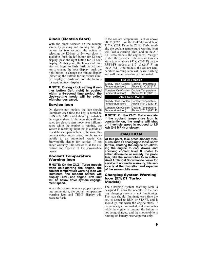
If the coolant temperature is at or above80° C (176° F) on the F5/F6/F8 models or115° C (239° F) on the Z1/Z1 Turbo mod-els, the coolant temperature warning iconwill flash a warning (alert) and on the Z1/Z1 Turbo models, the engine will “surge”to alert the operator. If the coolant temper-ature is at or above 93° C (200° F) on theF5/F6/F8 models or 117° C (243° F) onthe Z1/Z1 Turbo models, the coolant tem-perature warning icon will cease flashingand will remain constantly illuminated.
NOTE: On the Z1/Z1 Turbo modelsif the coolant temperature icon isconstantly on, the engine will shutoff if vehicle speed is reduced to 1.5kph (0.9 MPH) or slower.
Charging System Warning Icon (Z1/Z1 Turbo Models)
The Charging System Warning Icon isdesigned to warn the operator if the bat-tery charging system is not functioning.The icon should illuminate each time thekey is turned to RUN or START, and itshould go out when the engine starts. Ifthe icon stays illuminated or it illuminateswhile the engine is running, the battery isnot being charged, and the snowmobile isrunning on battery reserve power only.
F5/F6/F8 ModelsSteady Flash (Coolant Temperature Icon)
Coolant Temperature Above 80° C (176° F).
Constant On (Coolant Temperature Icon)
Coolant Temperature Above 93° C (200° F).
Z1/Z1 Turbo ModelsSteady Flash (Coolant Temperature Icon)
Coolant Temperature Above 115° C (239° F).
Constant On (Coolant Temperature Icon)
Coolant Temperature Above 117° C (243° F).
CAUTIONAt this point, take precautionary mea-sures such as changing to loose snowterrain, shutting the engine off (allow-ing the engine to cool down), andchecking coolant level. If unable toeither determine or remedy the prob-lem, take the snowmobile to an autho-rized Arctic Cat Snowmobile dealer forservice. If not under warranty, this ser-vice is at the discretion and expenseof the snowmobile owner.
10
If the Charging System Warning Iconilluminates, you should, as soon as possi-ble, take the snowmobile to an authorizedArctic Cat Snowmobile dealer for ser-vice. If not under warranty, this service isat the discretion and expense of thesnowmobile owner. The engine WILLNOT RUN without battery power.
Low Oil Warning Icon (F5/F6/F8 Models)
The Low Oil Warning Icon is designed toalert the snowmobile operator when theoil in the oil injection reservoir gets belowa prescribed level; however, it is highlyrecommended that a visual verification ofthe oil level in the reservoir be done priorto operating the snowmobile. Once theLow Oil Warning Icon illuminates duringoperation of the snowmobile, the operatormust periodically monitor the level of oilin the reservoir and must fill the reservoirthe next time gasoline is added to the gastank. The “alert level” of the Low OilWarning Icon is approximately equal to 1tankful of gasoline under normal operat-ing conditions.
Oil Pressure Warning Icon (Z1/Z1 Turbo Models)
The Oil Pressure Warning Icon indicatesengine oil pressure, not the oil level;however, if the oil level is low, it mayaffect oil pressure.
The icon should illuminate each time theignition switch is turned to RUN orSTART, and it should go out when theengine starts. If the icon illuminateswhile the engine is running, oil pressurehas been lost and the engine will auto-matically shut off.
If oil pressure is lost, use the followingprocedure to check the oil level:
1. With the engine off, remove theengine oil level stick and wipe itclean. Without screwing it in, set thestick back in the oil tank. Remove itand observe the oil level on thestick. If the oil level is at or belowthe ADD mark on the oil level stick,add only enough recommended oilto raise the level to the NORMALrange. DO NOT overfill the reser-voir with oil.
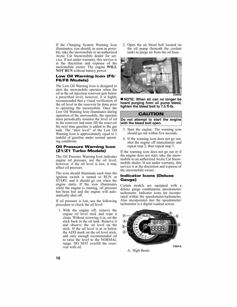
2. Open the air bleed bolt located onthe oil pump (beneath the coolanttank) to purge air from the oil hose.
ZJ004A
NOTE: When air can no longer beheard purging from oil pump bleed,tighten the bleed bolt to 7.5 ft-lb.
3. Start the engine. The warning iconshould go out within five seconds.
4. If the warning icon does not go out,shut the engine off immediately andrepeat step 2; then repeat step 3.
If the warning icon does not go out or ifthe engine does not start, take the snow-mobile to an authorized Arctic Cat Snow-mobile dealer. If not under warranty, thisservice is at the discretion and expense ofthe snowmobile owner.
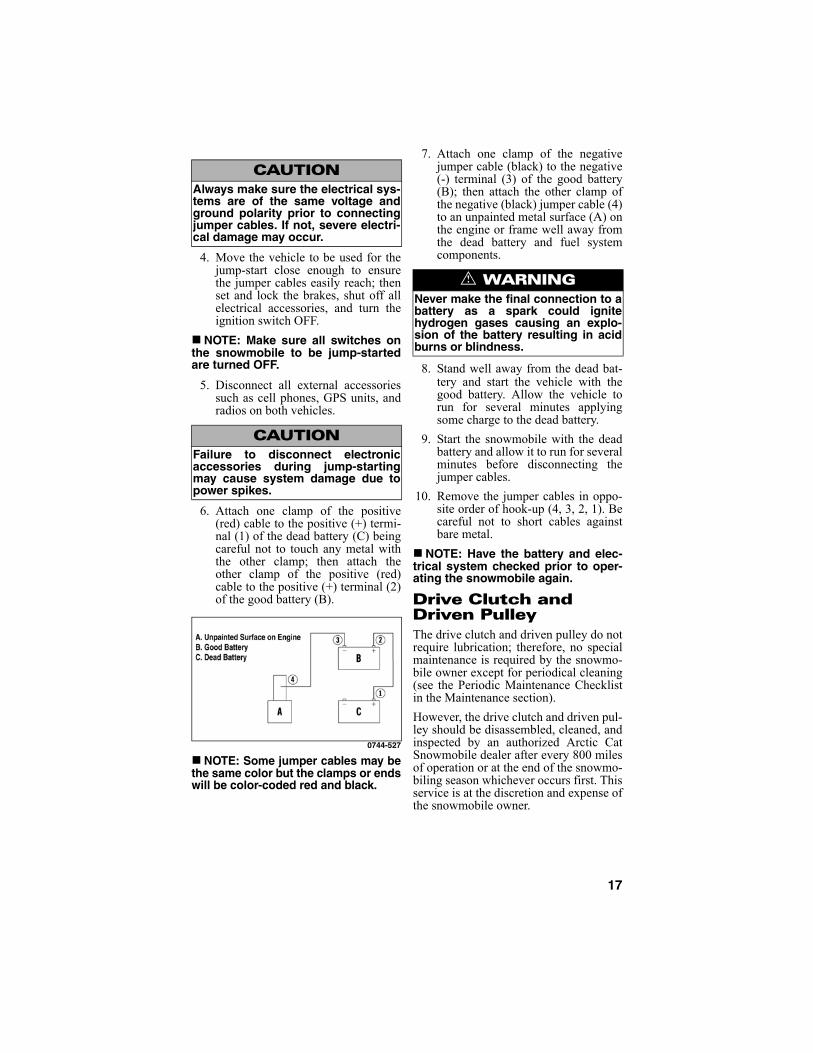
Indicator Icons (Deluxe Gauge)
Certain models are equipped with adeluxe gauge combination speedometer/tachometer. Indicator icons are incorpo-rated within the speedometer/tachometer.Also incorporated into the speedometer/tachometer is a digital readout screen.
FZ001A
A. High Beam
CAUTIONDo not attempt to start the enginewith the bleed bolt open.

11
B. Oil Pressure/Low Oil
C. Coolant Temperature
D. Increment Button
E. Select Button
F. Decrement Button
G. Service
H. Charging System (Z1/Z1 TurboModels)
RPM/MPH (kph)
By pushing the increment button once,the RPM and MPH will be displayed(one on the readout screen and one withthe needle). By pushing the button onceagain, the functions will be reversed.
By pushing the increment button (withspeed being displayed) for more than twoseconds, the display will change betweenstandard mph or metric kph.
With RPM displayed on the readoutscreen by pushing and holding the incre-ment button, maximum RPM will be dis-played on the readout screen. Themaximum RPM readout will reset whenthe decrement button is pushed (whilemaximum RPM is displayed).
Odometer/Trip-Meter (1)/Trip-Meter (2)/Hour-Meter
By pushing the decrement button, thereadout screen will display odometer,trip-meter (1), trip-meter (2), and hour-meter. To reset the trip meter with the tripmeter displayed, push and hold the decre-ment button until the display is cleared.The hour-meter readout will not reset.
Clock/Altimeter
By pushing the select button, the readoutscreen will display clock, altimeter, andmaximum altimeter.
With clock selected on the display bypushing and holding the select button fortwo seconds, the option of selecting the12-hour or 24-hour clock mode is avail-able. Push the increment button to togglebetween the 12-hour display and the 24-hour display. When desired mode is dis-played, push the select button.
At this point, the hours display will beginto flash. Push the increment button toincrease the hours; push the decrementbutton to decrease the hours. Pushing andholding a button will accelerate the num-ber display. When desired hour number isdisplayed, push the select button.
At this point, the minutes display willbegin to flash. Push the increment buttonto increase the minutes; push the decre-ment button to decrease the minutes.Pushing and holding a button will accel-erate the number display. When desiredminute number is displayed, push theselect button.
NOTE: During clock setting if nobutton (increment, decrement,select) is pushed within a 5-secondtime period, the clock-setting modewill be exited with changes saved.
The altimeter readout is based off baro-metric pressure and may require calibra-tion as weather conditions change.
To calibrate the altimeter to an estab-lished altitude with altimeter selected onthe display screen by pushing and hold-ing the select button for a minimum oftwo seconds, the acronym CAL will bedisplayed on the readout screen for onesecond; then the altitude value will flash.Push the increment button to increase thedisplayed altitude; push the decrementbutton to decrease the displayed altitude.Pushing and holding a button will accel-erate the number display.
NOTE: If MPH has been selected inthe speed readout, the altitude valuewill be displayed in feet. If kph has beenselected in the speed readout, the alti-tude value will be displayed in meters.
To reset the maximum altimeter readoutwith the maximum altimeter displayed,push and hold the select button for a min-imum of two seconds.

12
Service Icon
On electric start models, the icon shouldilluminate each time the key is turned toRUN or START, and it should go outwhenthe engine starts. If the icon stays illumi-nated (on electric start models) or it illumi-nates while the engine is running, thesystem is receiving input that is outside ofits established parameters. If the icon illu-minates indicating an error, take the snow-mobile to an authorized Arctic CatSnowmobile dealer for service. If not underwarranty, this service is at the discretionand expense of the snowmobile owner.
Coolant Temperature Warning Icon
NOTE: On the Z1/Z1 Turbo modelswhen cold-starting the engine, thecoolant temperature warning icon willilluminate, the readout screen willdisplay TEMP, and engine RPM limitwill be below drive system engage-ment speed.
When the engine reaches proper operat-ing temperature, the coolant temperaturewarning icon and TEMP display willcease to flash.
If the coolant temperature is at or above80° C (176° F) on the CFR/F5/F6/F8models or 115° C (239° F) on the Z1/Z1Turbo models, the coolant temperaturewarning icon will flash a warning (alert)and on the Z1/Z1 Turbo models, theengine will “surge” to alert the operator. Ifthe coolant temperature is at or above 93°C (200° F) on the CFR/F5/F6/F8 modelsor 117° C (243° F) on the Z1/Z1 Turbomodels, the coolant temperature warningicon will cease flashing and will remainconstantly illuminated.
NOTE: On the Z1/Z1 Turbo modelsif the coolant temperature icon isconstantly on, the engine will shutoff if vehicle speed is reduced to 1.5kph (0.9 MPH) or slower.
Charging System Warning Icon (Z1/Z1 Turbo Models)
The Charging System Warning Icon isdesigned to warn the operator if the bat-tery charging system is not functioning.The icon should illuminate each time thekey is turned to RUN or START, and itshould go out when the engine starts. Ifthe icon stays illuminated or it illumi-nates while the engine is running, the bat-tery is not being charged, and thesnowmobile is running on battery reservepower only.
If the Charging System Warning Iconilluminates, you should, as soon as possi-ble, take the snowmobile to an authorizedArctic Cat Snowmobile dealer for ser-vice. If not under warranty, this service isat the discretion and expense of thesnowmobile owner. The engine WILLNOT RUN without battery power.
CFR/F5/F6/F8 ModelsSteady Flash (Coolant Temperature Icon)
Coolant Temperature Above 80° C (176° F).
Constant On (Coolant Temperature Icon)
Coolant Temperature Above 93° C (200° F).
Z1/Z1 Turbo ModelsSteady Flash (Coolant Temperature Icon)
Coolant Temperature Above 115° C (239° F).
Constant On (Coolant Temperature Icon)
Coolant Temperature Above 117° C (243° F).
CAUTIONAt this point, take precautionarymeasures such as changing to loosesnow terrain, shutting the engine off(allowing the engine to cool down),and checking coolant level. If unableto either determine or remedy theproblem, take the snowmobile to anauthorized Arctic Cat Snowmobiledealer for service. If not under war-ranty, this service is at the discre-tion and expense of the snowmobileowner.

13
Low Oil Warning Icon (CFR/F5/F6/F8 Models)
The Low Oil Warning Icon is designed toalert the snowmobile operator when theoil in the oil injection reservoir gets belowa prescribed level; however, it is highlyrecommended that a visual verification ofthe oil level in the reservoir be done priorto operating the snowmobile. Once theLow Oil Warning Icon illuminates duringoperation of the snowmobile, the operatormust periodically monitor the level of oilin the reservoir and must fill the reservoirthe next time gasoline is added to the gastank. The “alert level” of the Low OilWarning Icon is approximately equal to 1tankful of gasoline under normal operat-ing conditions.
Oil Pressure Warning Icon (Z1/Z1 Turbo Models)
The Oil Pressure Warning Icon indicatesengine oil pressure, not the oil level;however, if the oil level is low, it mayaffect oil pressure.
The icon should illuminate each time theignition switch is turned to RUN orSTART, and it should go out when theengine starts. If the icon illuminateswhile the engine is running, oil pressurehas been lost and the engine will auto-matically shut off.
If oil pressure is lost, use the followingprocedure to check the oil level:
1. With the engine off, remove theengine oil level stick and wipe itclean. Without screwing it in, set thestick back in the oil tank. Remove itand observe the oil level on thestick. If the oil level is at or belowthe ADD mark on the oil level stick,add only enough recommended oilto raise the level to the NORMALrange. DO NOT overfill the reser-voir with oil.
2. Open the air bleed bolt located onthe oil pump (beneath the coolanttank) to purge air from the oil hose.
ZJ004A
NOTE: When air can no longer beheard purging from oil pump bleed,tighten the bleed bolt to 7.5 ft-lb.
3. Start the engine. The warning iconshould go out within five seconds.
4. If the warning icon does not go out,shut the engine off immediately andrepeat step 2; then repeat step 3.
If the warning icon does not go out or ifthe engine does not start, take the snow-mobile to an authorized Arctic Cat Snow-mobile dealer. If not under warranty, thisservice is at the discretion and expense ofthe snowmobile owner.
Diagnostic Codes Diagnostic codes are activated by theECU and may be displayed on the read-out screen for a number of reasons.
If a code is displayed while the engine isrunning, the ECU is receiving input thatis outside of its established parameters. Ifa code has been activated, take the snow-mobile to an authorized Arctic Cat Snow-mobile dealer for service. If not underwarranty, this service is at the discretionand expense of the snowmobile owner.
CFR/F5/F6/F8 Models
Additional codes are displayed on thereadout screen. Refer to the followingchart for diagnostic codes.
CAUTIONDo not attempt to start the enginewith the bleed bolt open.

14
* On certain models.
Z1/Z1 Turbo Models
These diagnostic codes are displayed onthe readout screen incorporated withinthe speedometer/tachometer. Refer to thefollowing chart for diagnostic codes.
* Turbo models
Handlebar TiltF-Series/Z1 Turbo - STD Models
The handlebar can be adjusted to theoperator’s preference. To adjust the han-dlebar, use the following procedure:
1. Loosen the four cap screws and locknuts securing the handlebar caps to theriser and the riser to the steering post.
744-439A
2. Adjust the handlebar to operator’sdesired tilt, tighten the lock nuts/capscrews evenly to 25 ft-lb, and checksteering for maximum right/leftturning capabilities.
NOTE: Do not rotate the handlebarto a position that allows air to enterthe brake system.
Cam Lever Style
The handlebar can be adjusted to theoperator’s preference. To adjust the han-dlebar, use the following procedure:
Code Trouble
2 Failure in injector(s).
4 Open or short circuit in barometric pressure sensor.
5 Open or short circuit in intake air tem-perature sensor.
6 Open or short circuit in water tempera-ture sensor.
7 Open or short circuit in throttle position sensor.
12 Failure in ignition coil.
16* Incorrect adjustment/failure in APV cable.
17* Failure in exhaust temperature sensor.
18* Failure in servomotor.
21* Failure in knock sensor.
OCTN* Low octane gasoline.
Code Trouble1 Failure in the fuel system.
2 Failure in injector (PTO).
3 Failure in injector (MAG).
4 Failure in barometric pressure sensor.
5 Open or short circuit in intake manifold air temperature sensor.
6 Open or short circuit in water tempera-ture sensor.
7 Open or short circuit in throttle position sensor.
8 Open or short circuit in manifold air pressure sensor.
9 Failure in crankshaft position sensor.
11 Failure in speed sensor.
12 Failure in coil (MAG).
13 Failure in coil (PTO).
14 Failure in ISC valve.
15 Failure in oxygen sensor.
19 Failure in camshaft position sensor.
21 Failure in knock sensor.
22* Failure in Injector (PTO secondary).
23* Failure in Injector (MAG secondary).
25 Failure in shifting system/gear position switch (relay).
26 Malfunction in air pressure sensor.
29 Failure in shifting system/gear selec-tion switch (reverse button).
OCTN* Low octane gasoline.
! WARNINGTighten lock nuts according to speci-fications to prevent unexpected“movement” of the handlebar duringoperation over rough terrain. DO NOTposition the handlebar so steering(maximum right/left turning capabili-ties) or throttle and brake controlsare affected.
Code Trouble

15
1. Press inward on the lock pin torelease the cam lever and “flip” thecam lever up.
741-427A
2. Adjust the handlebar up or down and/or rotate the handlebar to operator’sdesired position; then press down onthe cam lever until it “locks” in place.Check steering for maximum right/left turning capabilities.
NOTE: At this point, gently lift thecam lever without pressing in on thelock pin. If the cam lever cannot belifted, the lock pin is secure.
NOTE: Do not rotate the handlebarto a position that allows air to enterthe brake system.
3. Test the handlebar to ensure that itdoes not rotate within the riserblock. If it does not rotate, proceedto step 4. If it does rotate, release thecam lever and rotate the cam leverclockwise; then press down on thecam lever until the lock pin is prop-erly positioned and locked. Repeatthis procedure until the handlebar isproperly secured.
4. After the handlebar is “locked” inposition, release the cam lever androtate it one turn clockwise; thenpress down on the cam lever until it“locks” in place.
NOTE: At this point, gently lift thecam lever without pressing in on thelock pin. If the cam lever cannot belifted, the lock pin is secure.
Exhaust SystemThe exhaust system is designed to reducenoise and to improve the total perfor-mance of the engine. If any exhaust sys-tem component is removed from theengine and the engine is run, severeengine damage will result.
Air-Intake SilencerUsed in conjunction with the fuel intakesystem is a specially designed air-intakesilencer. The purpose of the silencer is toquiet the intake of fresh air. Since the fuelintake system is calibrated with the air-intake silencer in place, the engine mustnever be run with the silencer removed.Performance will not be improved if theair-intake silencer is removed. In con-trast, severe engine damage will occur.
CAUTIONIf at any time the lock pin will notengage into the locked position, doNOT operate the snowmobile. Take thesnowmobile to an authorized ArcticCat Snowmobile dealer for service.
! WARNINGCare must be taken to securely lockthe handlebar cam lever to preventunexpected “movement” of the han-dlebar during operation over roughterrain. DO NOT position the handle-bar so steering (maximum right/leftturning capabilities) or throttle andbrake controls are affected.
CAUTIONThese snowmobiles are notdesigned to be operated in dustyconditions. Operating the snowmo-bile in dusty conditions will result insevere engine damage.

16
Cooling System (CFR/F5/F6/F8/Z1/Z1 Turbo Models)These snowmobiles are equipped with aclosed liquid cooling system for enginecooling. The cooling system should beinspected daily for leakage and damage.Also, the coolant level should be checkeddaily. If leakage or damage is detected,take the snowmobile to an authorizedArctic Cat Snowmobile dealer for ser-vice. If not under warranty, this service isat the discretion and expense of thesnowmobile owner.
When filling the cooling system reser-voir, use an ethylene glycol-based cool-ant/water mixture which will satisfy thecoldest anticipated weather conditions ofyour area in accordance with the coolantmanufacturer’s recommendations.
For checking/filling cooling system, referto Coolant Level sub-section in the Main-tenance section.
Battery (Electric Start)It is extremely important that the batterybe maintained at full charge at all timesand that the battery connections be cleanand tight. If charging the battery becomesnecessary, refer to Battery sub-section inthe Maintenance section.
Jump-Starting (Z1/Z1 Turbo Models)
NOTE: Arctic Cat does not recom-mend jump-starting a snowmobilewith a dead battery but rather toremove the battery, service it, andcorrectly charge it; however, in anemergency, it may be necessary tojump-start a snowmobile. If so, usethe following procedure to carefullyand safely complete this procedure.
1. On the snowmobile to be jump-started,slide any terminal boots away.
2. Inspect the battery for any signs ofelectrolyte leaks, loose terminals, orbulging sides. Leaking or bulgingbattery cases may indicate a frozenor shorted battery.
3. Inspect the vehicle to be used forjump-starting to determine if voltageand ground polarity are compatible.The vehicle must have a 12-volt DC,negative ground electrical system.
CAUTIONOn the Z1/Z1 Turbo models, alwaysturn the ignition switch key to theOFF position when the snowmobileis not being used. Leaving the igni-tion switch in the ON position willresult in discharging the battery andpossible damage to the battery.
! WARNINGImproper handling or connecting ofa battery may result in severe injuryincluding acid burns, electricalburns, or blindness as a result of anexplosion. Always remove rings andwatches.
! WARNINGAny time service is performed on abattery, the following must beobserved: keep sparks, open flame,cigarettes, or any other flame away.Always wear safety glasses. Protectskin and clothing when handling abattery. When servicing a battery inan enclosed space, keep the areawell-ventilated.
! WARNINGIf any of these conditions exist, DONOT attempt to jump-start, boost, orcharge the battery. An explosioncould occur causing serious injury.
17
4. Move the vehicle to be used for thejump-start close enough to ensurethe jumper cables easily reach; thenset and lock the brakes, shut off allelectrical accessories, and turn theignition switch OFF.
NOTE: Make sure all switches onthe snowmobile to be jump-startedare turned OFF.
5. Disconnect all external accessoriessuch as cell phones, GPS units, andradios on both vehicles.
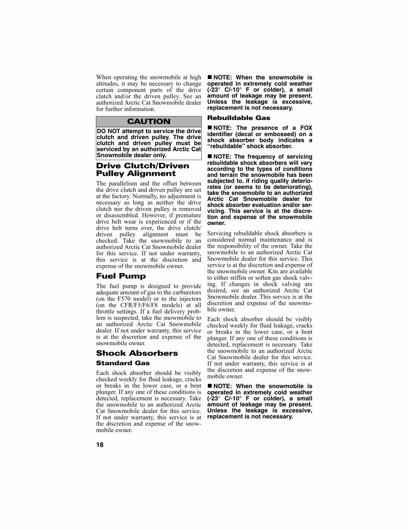
6. Attach one clamp of the positive(red) cable to the positive (+) termi-nal (1) of the dead battery (C) beingcareful not to touch any metal withthe other clamp; then attach theother clamp of the positive (red)cable to the positive (+) terminal (2)of the good battery (B).
0744-527
NOTE: Some jumper cables may bethe same color but the clamps or endswill be color-coded red and black.
7. Attach one clamp of the negativejumper cable (black) to the negative(-) terminal (3) of the good battery(B); then attach the other clamp ofthe negative (black) jumper cable (4)to an unpainted metal surface (A) onthe engine or frame well away fromthe dead battery and fuel systemcomponents.
8. Stand well away from the dead bat-tery and start the vehicle with thegood battery. Allow the vehicle torun for several minutes applyingsome charge to the dead battery.
9. Start the snowmobile with the deadbattery and allow it to run for severalminutes before disconnecting thejumper cables.
10. Remove the jumper cables in oppo-site order of hook-up (4, 3, 2, 1). Becareful not to short cables againstbare metal.
NOTE: Have the battery and elec-trical system checked prior to oper-ating the snowmobile again.
Drive Clutch and Driven PulleyThe drive clutch and driven pulley do notrequire lubrication; therefore, no specialmaintenance is required by the snowmo-bile owner except for periodical cleaning(see the Periodic Maintenance Checklistin the Maintenance section).
However, the drive clutch and driven pul-ley should be disassembled, cleaned, andinspected by an authorized Arctic CatSnowmobile dealer after every 800 milesof operation or at the end of the snowmo-biling season whichever occurs first. Thisservice is at the discretion and expense ofthe snowmobile owner.
CAUTIONAlways make sure the electrical sys-tems are of the same voltage andground polarity prior to connectingjumper cables. If not, severe electri-cal damage may occur.
CAUTIONFailure to disconnect electronicaccessories during jump-startingmay cause system damage due topower spikes.
! WARNINGNever make the final connection to abattery as a spark could ignitehydrogen gases causing an explo-sion of the battery resulting in acidburns or blindness.
18
When operating the snowmobile at highaltitudes, it may be necessary to changecertain component parts of the driveclutch and/or the driven pulley. See anauthorized Arctic Cat Snowmobile dealerfor further information.
Drive Clutch/Driven Pulley AlignmentThe parallelism and the offset betweenthe drive clutch and driven pulley are setat the factory. Normally, no adjustment isnecessary as long as neither the driveclutch nor the driven pulley is removedor disassembled. However, if prematuredrive belt wear is experienced or if thedrive belt turns over, the drive clutch/driven pulley alignment must bechecked. Take the snowmobile to anauthorized Arctic Cat Snowmobile dealerfor this service. If not under warranty,this service is at the discretion andexpense of the snowmobile owner.
Fuel PumpThe fuel pump is designed to provideadequate amount of gas to the carburetors(on the F570 model) or to the injectors(on the CFR/F5/F6/F8 models) at allthrottle settings. If a fuel delivery prob-lem is suspected, take the snowmobile toan authorized Arctic Cat Snowmobiledealer. If not under warranty, this serviceis at the discretion and expense of thesnowmobile owner.
Shock AbsorbersStandard Gas
Each shock absorber should be visiblychecked weekly for fluid leakage, cracksor breaks in the lower case, or a bentplunger. If any one of these conditions isdetected, replacement is necessary. Takethe snowmobile to an authorized ArcticCat Snowmobile dealer for this service.If not under warranty, this service is atthe discretion and expense of the snow-mobile owner.
NOTE: When the snowmobile isoperated in extremely cold weather(-23° C/-10° F or colder), a smallamount of leakage may be present.Unless the leakage is excessive,replacement is not necessary.
Rebuildable Gas
NOTE: The presence of a FOXidentifier (decal or embossed) on ashock absorber body indicates a“rebuildable” shock absorber.
NOTE: The frequency of servicingrebuildable shock absorbers will varyaccording to the types of conditionsand terrain the snowmobile has beensubjected to. If riding quality deterio-rates (or seems to be deteriorating),take the snowmobile to an authorizedArctic Cat Snowmobile dealer forshock absorber evaluation and/or ser-vicing. This service is at the discre-tion and expense of the snowmobileowner.
Servicing rebuildable shock absorbers isconsidered normal maintenance and isthe responsibility of the owner. Take thesnowmobile to an authorized Arctic CatSnowmobile dealer for this service. Thisservice is at the discretion and expense ofthe snowmobile owner. Kits are availableto either stiffen or soften gas shock valv-ing. If changes in shock valving aredesired, see an authorized Arctic CatSnowmobile dealer. This service is at thediscretion and expense of the snowmo-bile owner.
Each shock absorber should be visiblychecked weekly for fluid leakage, cracksor breaks in the lower case, or a bentplunger. If any one of these conditions isdetected, replacement is necessary. Takethe snowmobile to an authorized ArcticCat Snowmobile dealer for this service.If not under warranty, this service is atthe discretion and expense of the snow-mobile owner.
NOTE: When the snowmobile isoperated in extremely cold weather(-23° C/-10° F or colder), a smallamount of leakage may be present.Unless the leakage is excessive,replacement is not necessary.
CAUTIONDO NOT attempt to service the driveclutch and driven pulley. The driveclutch and driven pulley must beserviced by an authorized Arctic CatSnowmobile dealer only.

19
Standard-Lug TrackAccelerated wear strip wear caused byoperating on hard-packed snow condi-tions is NOT covered under Arctic CatInc. warranty policy.
Deep-Lug TrackSome models are equipped with a deep-lug track which is specially designed foruse in powder snow riding conditions.When the deep-lug track is operated inhard-packed snow conditions, it will runslightly slower than a standard-lug trackand it will accelerate wear strip wear. Todecrease the amount of wear strip wear,slower speeds must be maintained whenoperating on hard-packed trails. Acceler-ated wear strip wear caused by operatinga deep-lug track on hard-packed snowconditions is NOT covered under ArcticCat Inc. warranty policy.
NOTE: If operating on ice or hard-packed snow conditions, it is recom-mended that Ice Scratchers (p/n4639-958) be installed to reducewear strip and engine overheating.
Track Studs NOTE: Stud or hooker plate installa-tion will void track and tunnel warranty.
NOTE: Stud installation can be per-formed by the snowmobile owner ifqualified to do so. If the owner doesnot feel qualified, take the snowmo-bile to an authorized Arctic Cat Snow-mobile dealer for this service. Thisservice is at the discretion andexpense of the snowmobile owner.
NOTE: To prevent tunnel damagefrom the studs, Tunnel Protector Kit(p/n 4639-771) for the F570 model or(p/n 4639-968) for CFR models mustbe installed.
For proper installation, use the followingprocedure:
1. Using the stud template (see chart),mark the desired stud pattern to beused.
2. Using the proper-sized stud holedrill bit, drill out the stud holes.
3. Push the stud through the hole frominside the track; then place thedomed support plate and lock nut onthe exposed stud.
4. Using a wrench to secure the stud,tighten the lock nut on the exposed stud.
It is also recommended that wheneverstuds are installed on a track, carbidewear bars should be installed on the skis.Carbide wear bars complement the trackstuds to balance steering control underthese conditions. The length of the car-bide on the wear bars should be propor-tionate to the number of track studs (i.e.small number of track studs — shortlength of carbide...many track studs —long length of carbide). The proper pro-portion between the number of studs andcarbide length on the wear bar will main-tain steering balance.
! WARNINGWhen installing studs on a single-plytrack, it is important to use ArcticCat-approved studs (proper headdiameter). If approved studs (properhead diameter) are not used, studscould tear free of the track causingpossible injury or even death. Con-sult an authorized Arctic Cat Snow-mobile dealer for information.
CAUTIONIf installing studs on the CFR mod-els, a short Snowflap (p/n 5639-232)must be installed or component dam-age will occur.
Stud Template ChartTrack Length p/n
128 in. 4639-443144 in. 5639-160
! WARNINGAlways balance the snowmobile withthe proper proportion between thenumber of studs and carbide lengthon the wear bars. Do not “over drive”conditions; use common sense in alloperating conditions.

20
Reverse OperationCFR/F570/F8 Models
The engine reverse function offers theoperator the convenience of being able toback up the snowmobile rather than hav-ing to turn the snowmobile around byhand. This feature, under most situations,should not be used to free a stuck snow-mobile as it will tend to dig the skisdeeper into the snow. Always use mini-mal speed when operating in reverse andcome to a complete stop before shiftingfrom either forward to reverse or reverseto forward.
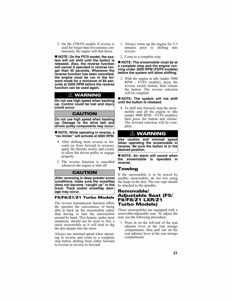
Shifting Into Reverse
741-438A
NOTE: Correct drive belt tension(deflection) is important for thereverse function to operate properly.If the belt is too tight, difficulty inengaging reverse will be experi-enced (the reverse function willmake up to three attempts to engageinto reverse, and if the function isnot completed after the thirdattempt, the engine will shut down).
1. Always warm up the engine for 2-3minutes prior to shifting intoreverse. The reverse function is can-celled when engine temperature isbelow -22° F (-30° C) or above 176°F (80° C).
2. Shift only with the engine at idleRPM and the snowmobile com-pletely stopped. The reverse func-tion will not engage if engine speedis above 4000 RPM.
NOTE: If attempting to shift intoreverse at too high engine RPM(above 4000 RPM), the reverse func-tion will be cancelled and the coolanttemperature warning icon will flash.This indicates the reverse switchbutton was pressed at too high RPM.The operator must reduce engineRPM below 4000 and press the but-ton a second time.
3. Upon pressing the reverse switchbutton, the reverse function willmake up to three attempts to engageinto reverse. If the function is notcompleted after the third attempt,the engine will shut down.
Operating in Reverse
1. When reverse is engaged, a reverseicon will illuminate in the speedom-eter/tachometer and a reverse alarmwill sound.
2. If the throttle lever is compressedbefore complete reverse engage-ment, the engine may shut down.Always wait for the reverse icon toilluminate and the reverse alarm tosound before backing up.
CAUTIONDo not use studs that are more than9.525 mm (0.375 in.) longer than thetrack lug height.
! WARNINGDo not operate a snowmobile withloose studs as they may be thrownfrom the track. Always use a shieldedsafety stand whenever performingany maintenance or adjustments.
! WARNINGDO NOT stand behind the snowmo-bile or near the rotating track.NEVER run the track at high speedwhen the track is suspended.
CAUTIONNever shift into reverse while thesnowmobile is moving forward as itis hard on the driven pulley torquebracket and the cam rollers.
CAUTIONNever engage the electric starter orpull the recoil starter rope when theengine is running or when operatingin reverse. Damage to the engine and/or either the electric start or recoilstart system will occur.
21
3. On the CFR/F8 models if reverse isused for longer than five minutes con-tinuously, the engine will shut down.
NOTE: On the F570 model, the sys-tem will not shift until the button isreleased. Also, the reverse functionwill cancel if operated in reverse lon-ger than 45 seconds. Whenever thereverse function has been cancelled,the engine must be run in the for-ward mode for a minimum of 60 sec-onds at 2000 RPM before the reversefunction can be used again.
NOTE: While operating in reverse, a“rev-limiter” will activate at 6000 RPM.
4. After shifting from reverse to for-ward (or from forward to reverse),apply the throttle slowly and evenlyto allow the driven pulley to engageproperly.
5. The reverse function is cancelledwhenever the engine is shut off.
F5/F6/Z1/Z1 Turbo Models
The reverse transmission function offersthe operator the convenience of beingable to back up the snowmobile ratherthan having to turn the snowmobilearound by hand. This feature, under mostsituations, should not be used to free astuck snowmobile as it will tend to digthe skis deeper into the snow.
Always use minimal speed when operat-ing in reverse and come to a completestop before shifting from either forwardto reverse or reverse to forward.
1. Always warm up the engine for 2-3minutes prior to shifting intoreverse.
2. Come to a complete stop.
NOTE: The snowmobile must be ata complete stop and the engine run-ning under 3000 RPM (F5/F6 models)before the system will allow shifting.
3. With the engine at idle (under 3000RPM - F5/F6 models), press thereverse switch button; then releasethe button. The reverse selectionwill be complete.
NOTE: The system will not shiftuntil the button is released.
4. To shift into forward, stop the snow-mobile and all the engine to idle(under 3000 RPM - F5/F6 models);then press the button and release.The forward selection will be com-plete.
NOTE: An alarm will sound whenthe snowmobile is operated inreverse.
TowingIf the snowmobile is to be towed byanother snowmobile, do not tow usingthe loops in the skis. The tow rope shouldbe attached to the spindles.
Removable/Adjustable Seat (F5/F6/F8/Z1 LXR/Z1 Turbo Models)These snowmobiles are equipped with aremovable/adjustable seat. To adjust theseat, use the following procedure:
1. Press in on the left-end of the seatadjuster lever at the rear storagecompartment; then pull out on theseat adjuster lever at the rear storagecompartment.
! WARNINGDo not use high speed when backingup. Control could be lost and injurycould occur.
CAUTIONDo not use high speed when backingup. Damage to the drive belt anddriven pulley components may occur.
CAUTIONAfter reversing in deep powder snowconditions, make sure the snowflapdoes not become “caught up” in thetrack. Track and/or snowflap dam-age may occur.
! WARNINGUse caution and minimal speedwhen operating the snowmobile inreverse. Be sure the button is in thedesired position.

22
0744-465
2. Lift up on the back of the seat; thenmove the front of the seat up ordown into one of the seven availablepositions.
3. Press down on the rear of the seat;then secure the seat by releasing theseat adjuster lever.
To remove the seat, use the followingprocedure:
1. Adjust the seat to the lowest posi-tion; then while lifting on the topforward part of the seat, remove theself-tapping screw from the rightside of the seat support assembly.
741-718A
2. Press in on the left-end of the seatadjuster lever at the rear storagecompartment; then pull out on theseat adjuster lever.
3. Lift on the back of the seat and moveit forward and upward to remove itfrom the chassis.
To install the seat, use the following pro-cedure:
1. With the seat adjuster lever pulled out,slide the front of the seat into positionon the chassis; then with seat positionselected, lower the rear of the seatonto the rear storage compartment.
2. Press down on the rear of the seat;then secure the seat by releasing theseat adjuster lever.
3. With the seat adjusted to the lowestposition, install the self-tappingscrew into the right side of the seatsupport assembly.
Arctic Power Valve (APV) System (CFR/F6/F8 Models)
This RPM controlled servomotor (servo)actuated system adjusts the size of theexhaust ports to provide peak perfor-mance throughout the RPM range.
The system consists of an exhaust valveassembly mounted to the exhaust side ofeach cylinder and connected by adjust-able cables to an electronic servomounted beneath the hood.
NOTE: The mounting location of theservo will vary from model to model.
CAUTIONDo not use the adjuster lever to liftthe seat.
! WARNINGMake sure the seat is securelylocked in place or personal injurymay result.
CAUTIONDo not use the adjuster lever to liftthe seat.
! WARNINGMake sure the self-tapping screw issecurely tightened and the seat issecurely locked in place or personalinjury may result.
CAUTIONThe recommended engine oil to useis either Arctic Cat APV Synthetic 2-Cycle Oil or Formula SS Semi-Syn-thetic Oil (see Gasoline-Oil - Recom-mended Injection Oil sub-section inthis section). Any substitute maycause an APV malfunction.

23
739-152F
At low RPM, the exhaust valves are heldin the DOWN position by return springs.This gives the engine a “low port”exhaust design calibrated to providemaximum low RPM power and improvefuel economy at trail speeds.
739-152G
At high RPM, the exhaust valves areraised. This creates a “high port” exhaustdesign calibrated to provide maximumperformance at high RPM.
739-152H
NOTE: The RPM ranges will varyfrom model to model.
NOTE: If the servomotor cyclesthree times and then shuts down, theexhaust valve cables are notadjusted correctly. The exhaustvalves may also be sticking.
NOTE: APV cleaning may be doneby the snowmobile owner if qualifiedto do so. If the owner does not feelqualified, take the snowmobile to anauthorized Arctic Cat Snowmobiledealer for this service. This serviceis at the discretion and expense ofthe snowmobile owner.
Exhaust Controlled Timing (ECT) System (CFR/F6/F8 Models)This system automatically adjusts theignition timing to provide maximum per-formance through a variety of operatingconditions. The ECU receives input onengine RPM (demand) and exhaust pipetemperature (engine condition) andadjusts the ignition timing accordingly.This system is not adjustable and is main-tenance free.
If a system fault is suspected, use an ohm-meter to check continuity of the exhaustpipe temperature sensor located in theexpansion chamber. A reading of either 0ohm or infinity indicates a failed sensor.
0737-314
NOTE: A disabled ECT systemWILL NOT cause engine damage;however, a failed ECT system willhave slower throttle response andmay produce slightly less top-endperformance.
24
Operating InstructionsStarting and Stopping EngineIt is imperative that the brake system bechecked for wear and proper operation andthat all safety checks found in the accom-panying Snowmobile Safety Handbook beperformed before attempting to start theengine. Also, on the F570 model, be surethe correct carburetor main jets for theoperating temperature, altitude, andgasoline are being used. After the enginehas been started, check the headlights(high and low beam), taillight, and brake-light to be sure they are working properlyand adjusted correctly. Make sure all lightsare clean to provide maximum illumina-tion. The headlight and taillight must beclean and must be illuminated wheneverthe engine is running.
1. Test the operation of the brake sys-tem by compressing the brake lever.The brake lever must feel firm whencompressed; then while holding thebrake lever in the compressed posi-tion, measure the distance betweenthe brake lever and the handlebar.The distance must be greater than2.54 cm (1 in.).
741-328C
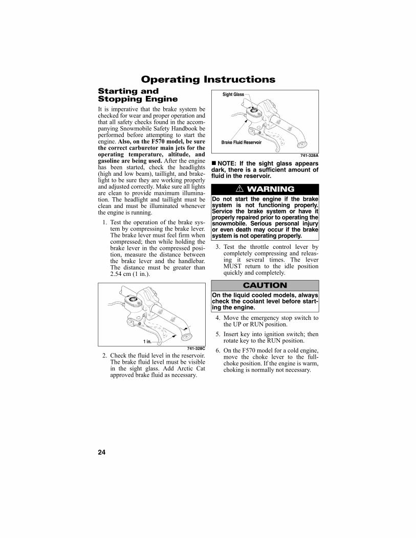
2. Check the fluid level in the reservoir.The brake fluid level must be visiblein the sight glass. Add Arctic Catapproved brake fluid as necessary.
741-328A
NOTE: If the sight glass appearsdark, there is a sufficient amount offluid in the reservoir.
3. Test the throttle control lever bycompletely compressing and releas-ing it several times. The leverMUST return to the idle positionquickly and completely.
4. Move the emergency stop switch tothe UP or RUN position.
5. Insert key into ignition switch; thenrotate key to the RUN position.
6. On the F570 model for a cold engine,move the choke lever to the full-choke position. If the engine is warm,choking is normally not necessary.
! WARNINGDo not start the engine if the brakesystem is not functioning properly.Service the brake system or have itproperly repaired prior to operating thesnowmobile. Serious personal injuryor even death may occur if the brakesystem is not operating properly.
CAUTIONOn the liquid cooled models, alwayscheck the coolant level before start-ing the engine.

25
0725-001
NOTE: On the F570 model whenthe engine is being started with aidof the choke, DO NOT COMPRESSTHE THROTTLE CONTROL LEVER. Ifthe throttle control lever is com-pressed, the engine will not startbecause the gas/air mixture will betoo lean. To start a warm engine,however, the throttle control levermay have to be compressed slightly.
NOTE: On the CFR/F5/F6/F8 mod-els when a cold engine is beingstarted, DO NOT COMPRESS THETHROTTLE CONTROL LEVER. If thethrottle control lever is compressed,the engine will not start because thefuel/air mixture will be too lean.
NOTE: On the CFR/F5/F6/F8 mod-els when a warm engine is beingstarted, the throttle control lever mayhave to be compressed slightly.
7. On models with manual start, pullthe recoil handle slowly until resis-tance is felt; then give a short quickpull. Repeat until the engine starts.
NOTE: On large-diasplacementengines in extremely cold weather, pullthe recoil handle slowly two to threetimes to begin the starting procedure.
NOTE: On electric start models,rotate the key to the START position;then when the engine starts, releasethe key.
8. On the F570 model when the enginestarts, allow it to warm up forapproximately 30 seconds with thechoke lever in the full-choke posi-tion. After the 30-second warm-up,move the choke lever to the middleposition. The choke lever should bemoved to the OFF position whenengine is warm. Slight throttle con-trol lever compression may be nec-essary after the engine starts andduring warm-up. Idle the engineseveral minutes until the engine hasreached normal operating tempera-ture.
NOTE: On the CFR/F5/F6/F8 mod-els when the engine starts, allow it towarm up properly. Idle the engineseveral minutes until the engine hasreached normal operating tempera-ture. Do not idle the engine forexcessively long periods of time.
9. On the Z1/Z1 Turbo models, there isa “cold drive-away” function incor-porated within the engine. This func-tion is active until the engine reachesoperating temperature (see ColdDrive-Away Function sub-section inthe General Information section).
CAUTIONTo avoid damaging the recoil starter,DO NOT pull the recoil rope to itslimit or release the recoil handlefrom an extended position. Allow therope to rewind slowly.
CAUTIONDo not continuously run the starterfor more than 5 seconds at a time.
CAUTIONIt is extremely important that theengine is properly warmed up beforesubjecting the engine to high speedoperation or heavy loads. Theengine should be allowed to idle atleast 3-4 minutes before it is oper-ated at more than 1/2 throttle. Inextremely cold conditions, thewarm-up time will be longer. Coldseizure and piston scuffing causedby insufficient warm-up will not becovered by warranty. Also, do notidle the engine for excessively longperiods of time.
26
10. Flooding — On the F570 model ifthe engine does not start when thechoke is being used but seems readyto start, move the choke lever to theOFF position. Engage the brakelever lock; then compress the throt-tle control lever fully and try to startthe engine. When the engine starts,release the throttle control leverimmediately. After the warm-up,release the brake lever lock.
NOTE: Continued choking willcause the engine to flood more.
NOTE: On the F570 models if theengine fails to start during theattempt with the throttle control levercompressed, remove the spark plugsand clean and dry them thoroughly orinstall a new set of properly gapped,recommended spark plugs.
11. Flooding — On the CFR/F5/F6/F8/Z1/Z1 Turbo models if the enginedoes not start but seems ready tostart, engage the brake lever lock;then compress the throttle controllever fully and try to start the engine.When the engine starts, release thethrottle control lever immediately.After the warm-up, release the brakelever lock.
NOTE: On the CFR/F5/F6/F8 mod-els if the engine fails to start duringthe attempt with the throttle controllever compressed, remove the sparkplugs and clean and dry them thor-oughly or install a new set of properlygapped, recommended spark plugs.
NOTE: On the Z1/Z1 Turbo modelsif spark plugs must be replaced, takethe snowmobile to an authorizedArctic Cat Snowmobile dealer forinspection and service. This serviceis at the discretion and expense ofthe snowmobile owner.
12. To shut off the engine, turn the igni-tion key to the OFF position or pushthe emergency stop switch to theDOWN position.
BrakingThe following items are items that theoperator must be familiar with whenoperating this snowmobile and itshydraulic brake system. Important addi-tional information on the proper mainte-nance of the brake system is found in theMaintenance section.
1. Use the brakes wisely. Each time thebrakes are applied in all hydraulicbrake systems (including automotiveapplications), heat is transferred tothe brake fluid. The amount of heattransferred during high speed stopsand/or repetitive use may be highenough to boil the brake fluid andcause the brakes to either fade or maycause an unexpected loss of brakes.
If this occurs, the brake fluid requiresa cool-down period before the brakeswill again function properly. Thiscool-down period will vary depend-ing upon the ambient air temperatureand the temperature of the brakefluid. If loss of brakes has occurredbecause of high fluid temperatures,do not operate the snowmobile untilthe cool-down period has expired andbrake lever firmness has returned.
CAUTIONOn the Z1/Z1 Turbo models, alwaysturn the ignition switch key to theOFF position when the snowmobileis not being used. Leaving the igni-tion switch in the ON position willresult in discharging the battery andpossible damage to the battery.
! WARNINGExcessive repetitive use of thehydraulic brake for high speed stopswill cause overheating of the brakefluid and premature brake pad wearwhich will result in an unexpectedloss of brakes.

27
2. Be sure to maintain the brake fluid atthe proper level and take care not toget any moisture in the system asmoisture in the brake fluid lowers theboiling point. If the brake fluid is everboiled (by high speed stops or repeti-tive use) or if moisture is allowed toenter the system, it must be changed.Never substitute or mix different typesor grades of brake fluid.
3. Never ride the brake. Even main-taining minimal pressure on thebrake lever will cause the brake padsto drag on the disc and may overheatthe brake fluid.
4. The brake lever lock is not a parkingbrake and should not be applied forperiods exceeding 5 minutes.NEVER OPERATE THE SNOW-MOBILE WITH THE BRAKELEVER LOCK ENGAGED.
5. Pumping the brake lever is permissi-ble; however, if pumping the brakelever more than twice is necessary toobtain the necessary stopping power,immediately take the snowmobile toan authorized Arctic Cat Snowmo-bile dealer for service. If not underwarranty, this service is at the discre-tion and expense of the snowmobileowner.
6. When new brake pads are installed, a“burnishing” process is required. Drivethe snowmobile slowly and compressthe brake lever several times until thepads just start to heat up; then allowthem to thoroughly cool down. Thisprocess stabilizes the pad material andextends the life of the pads.
Emergency StoppingThere are several methods of stopping orslowing the snowmobile under a varietyof situations. Identified in the followingchart are the ways a snowmobile may bebrought to a stop and the effectivenessunder normal conditions.
Throttle/Ignition Monitor SwitchThe throttle control is equipped with amonitor switch for safety purposes whichwill stop the engine when a loss of returnspring force occurs. If ice forms in thethrottle system or if there is some othermalfunction of the throttle system result-ing in a loss of return spring force, themonitor switch will stop the engine whenthe throttle control lever is released.
If the snowmobile engine stops abruptlywhen the throttle control lever is releasedand the activation of the monitor switch issuspected, use the following procedure:
! WARNINGUse only Arctic Cat approved brakefluid. Never substitute or mix differ-ent types or grades of brake fluid.Brake loss can result. Check brakefluid level and pad wear before eachuse. Brake loss can result in severeinjury or even death.
! WARNINGThe brake lever lock is not a parkingbrake and should not be applied forperiods exceeding 5 minutes. Thebrake lever lock maintains the brakelever in the compressed position andmaintains pressure against thebrake disc; however, after a period oftime, the pressure applied to thebrake disc may relax below theamount required to hold the snow-mobile stationary.
Item Function Condition
Emergency Stop Switch
interrupts igni-tion circuit
ALL
Throttle/Ignition Monitor Switch
interrupts igni-tion circuit
ALL
Ignition Switch interrupts igni-tion circuit
ALL
Brake slows the ACT drive
ALL
Choke (F570 model)
floods the engine 1/2 throt-tle or less
! WARNINGIf any malfunction of the throttle sys-tem occurs (such as freezing in fluffysnow) and the monitor switch doesnot shut off the engine, press downon the emergency stop switch IMME-DIATELY to stop the engine. DO NOTstart the engine until the malfunctionin the throttle system has beenlocated and corrected.

28
1. Rotate the ignition key to the OFFposition.
2. Remove ice and snow from thethrottle system and wait 5-10 min-utes for the engine heat to thaw icefrom the throttle system.
3. Test the throttle control lever bycompressing and releasing it severaltimes. The lever MUST return to theidle position quickly and completely.
NOTE: If the throttle control leveroperates properly and the enginedoes not start, compress the throttlelever slightly (approximately 1/8throttle) and try starting the engine.If the engine now starts and stopswhen the throttle lever is released,take the snowmobile to an autho-rized Arctic Cat Snowmobile dealerfor service. If not under warranty,this service is at the discretion andexpense of the snowmobile owner.
4. If the throttle control lever operatesproperly, rotate the ignition key tothe RUN position and go throughnormal starting procedures.
NOTE: On the F570 model if thethrottle control lever operates prop-erly and the engine does not start,either a malfunctioning monitorswitch or a misadjusted magneticcarburetor switch may be the prob-lem. Take the snowmobile to anauthorized Arctic Cat Snowmobiledealer for service. If not under war-ranty, this service is at the discretionand expense of the snowmobileowner. However, if a dire emergencyexists wherein the engine must bestarted, disconnect the carburetorsafety switch connectors. If discon-nection of the carburetor safetyswitch connectors is needed to startthe engine, take the snowmobile toan authorized Arctic Cat Snowmo-bile dealer for service as soon aspossible. If not under warranty, thisservice is at the discretion andexpense of the snowmobile owner.
NOTE: To access the switch connec-tors, open the left-side access paneland remove the belt guard; thenlocate the switch on the left-side ofthe carburetor and trace the wire tothe connector.
0743-448
NOTE: On the CFR/F5/F6/F8/Z1/Z1 Turbo models if the throttle con-trol lever operates properly and theengine does not start, a malfunction-ing monitor switch may be the prob-lem. Take the snowmobile to anauthorized Arctic Cat Snowmobiledealer for service. If not under war-ranty, this service is at the discretionand expense of the snowmobileowner. However, if a dire emergencyexists wherein the engine must bestarted, disconnect the throttle mon-itor switch located in the right-sidehandlebar control.
NOTE: On the CFR/F5/F6/F8/Z1/Z1Turbo models if disconnection of thethrottle monitor switch is needed tostart the engine, take the snowmobileto an authorized Arctic Cat Snowmo-bile dealer for service as soon aspossible. If not under warranty, thisservice is at the discretion andexpense of the snowmobile owner.
! WARNINGIf the throttle control lever does notwork properly, DO NOT ATTEMPT TOSTART THE ENGINE.

29
NOTE: The monitor switch is nowbypassed. All other ignition/electricalfeatures (ignition switch, emergencystop switch, headlight, taillight, andbrakelight) will operate properly.
Varying Altitude OperationOperating a snowmobile at varying alti-tudes requires changes in performancecomponents. These changes affect drivetrain components (on certain models) andcarburetion components (F570 models).
The altitude information decal is locatedon the belt guard of the snowmobile (F-Series models) or beneath the hood of thesnowmobile (CFR models). On the F570model, the information is incorporatedinto the Carburetor Jet Chart decal on thebelt guard.
NOTE: Just as important as cali-brating the snowmobile for higheraltitudes is recalibrating the snow-mobile when going to lower alti-tudes.
NOTE: Carburetion and drive trainchanges can be made by the snow-mobile owner if qualified to do so. Ifthe owner does not feel qualified,take the snowmobile to an autho-rized Arctic Cat Snowmobile dealerfor this service. This service is at thediscretion and expense of the snow-mobile owner.
! WARNINGUnder no circumstances should dis-connection of the throttle control wir-ing harness be used as a substitutefor the monitor switch during normaloperation of the snowmobile. Per-sonal injury and damage could occurif the throttle system malfunctions orif the operator is unable to stop theengine in an emergency. If the snow-mobile must be operated with a dis-connected throttle control wiringharness, EXTREME CAUTION MUSTBE TAKEN. NEVER EXCEED 10 MPHWITH THE THROTTLE CONTROLWIRING HARNESS DISCONNECTED.
CAUTIONOn the F570 model, carefully followthe Carburetor Jet Chart recommen-dations for proper altitude calibra-tion.

30
LubricationACT Drive Gear CaseIt is very important that the gear case beflushed and the lubricant be replacedafter each season of use. Arctic Cat rec-ommends that the flushing and replacingbe done prior to off-season storage.
NOTE: Flushing the gear case andreplacing the lubricant can be doneby the snowmobile owner if qualifiedto do so. If the owner does not feelqualified, take the snowmobile to anauthorized Arctic Cat Snowmobiledealer for this service. This serviceis at the discretion and expense ofthe snowmobile owner.
To flush the gear case and replace thelubricant, use the following procedure:
NOTE: Gear case profiles will varyfrom model to model. Determinewhich style is being serviced andrefer to the appropriate illustration.
1. Open the left-side access panel; thenremove the panel and the belt guard.
2. Remove the drive belt (see Drive Beltsub-section in the Maintenance sec-tion); then remove the driven pulley.
NOTE: If excessive oil deposits arenoticed, take the snowmobile to anauthorized Arctic Cat Snowmobiledealer for service. If not under war-ranty, this service is at the discretionand expense of the snowmobileowner.
3. Using Handlebar Stand (p/n 5639-152) or a suitable substitute, tip thesnowmobile onto its right side.
NOTE: It is recommended that thegas tank be nearly empty (less than1/4 full) when tipping the snowmo-bile.
4. Remove the drain plug from the gearcase; then install a drain adapter fit-ting with hose into the drain plughole.
744-133D
0743-456
0741-334
NOTE: To aid in draining the lubri-cant, it is advisable to fashion a drainadapter by acquiring a fitting - GearCase Drain Fitting (p/n 0644-552) - anda length of 3/8-in. hose.
5. Tip the snowmobile back to theupright position; then place a drainpan on the floor next to the drainhose and tip the snowmobile towardits left side far enough to allow thelubricant to drain from the gear caseinto the drain pan.
NOTE: It is critical that the snow-mobile is on a level surface toensure the lubricant drains properlyand completely.
6. Secure the snowmobile in this posi-tion until the lubricant is completelydrained.
CFR Models
F570/F8Models
F5/F6/Z1/Z1Turbo Models

31
7. When the lubricant has completelydrained from the gear case, tip thesnowmobile back to the upright posi-tion, remove the drain adapter, andinstall and securely tighten the drainplug; then remove the check/fill plug.
8. Pour Arctic Cat ACT Drive FlushFluid (p/n 4639-333) into the check/fill hole; then install the plug.Tighten securely.
9. Install the driven pulley; then installthe drive belt (see Drive Belt sub-section in the Maintenance section)and the belt guard.
10. Install the left-side access panel;then close the access panel.
11. Position the tips of the skis against awall; then using a shielded safetystand, raise the rear of the snowmo-bile off the floor making sure thetrack is free to rotate.
12. Start the engine and accelerateslightly. Use only enough throttle toturn the track several revolutions.SHUT ENGINE OFF.
13. Open the left-side access panel; thenremove the panel and the belt guard.
14. Remove the drive belt (see Drive Beltsub-section in the Maintenance sec-tion); then remove the driven pulley.
15. Using Handlebar Stand (p/n 5639-152) or a suitable substitute, tip thesnowmobile onto its right side.
16. Remove the drain plug from the gearcase; then install the drain adapter fit-ting with hose into the drain plug hole.
17. Tip the snowmobile back to theupright position; then place a drainpan on the floor next to the drainhose and tip the snowmobile towardits left side far enough to allow theflush fluid to drain from the gearcase into the drain pan.
18. Secure the snowmobile in this posi-tion until the flush fluid is com-pletely drained.
19. When the fluid has completelydrained from the gear case, tip thesnowmobile back to the upright posi-tion, remove the drain adapter, andinstall and securely tighten the drainplug; then remove the check/fill plug.
20. Pour the exact amount of Arctic CatSynthetic ACT Gear Case Fluid intothe check/fill hole; then install theplug. Tighten securely.
CAUTIONIt is critical that all of the old lubri-cant be drained from the gear caseprior to flushing the gear case.
CAUTIONDo not add more or less than therecommended amount (6 fl oz) offlush fluid to the gear case.
! WARNINGThe tips of the skis must be posi-tioned against a wall or similar object.
! WARNINGDO NOT stand behind the snowmo-bile or near the rotating track.NEVER run the track at high speedwhen the track is suspended.
CAUTIONIt is critical that all of the flush fluidbe drained from the gear case priorto filling with new lubricant.
CAUTIONThe correct lubricant to use in thegear case is Arctic Cat SyntheticACT Gear Case Fluid (see chart).Any substitute may cause seriousdamage to the drive system.
Gear Case Lubricant
Model p/n Amount
F5/F6/Z1/Z1 Turbo
4639-628 354 ml (12 fl oz)
CFR/F570/F8 5639-219 444 ml (15 fl oz)
CAUTIONDo not add more or less than therecommended amount of lubricantto the gear case or damage to thegear case will occur. Oil level shouldbe at the Oil Fill Level on the gearcase cover.

32
21. Install the driven pulley; then installthe drive belt (see Drive Belt sub-section in the Maintenance section)and the belt guard.
22. Install the left-side access panel;then close the access panel.
Front SuspensionNOTE: Arctic Cat recommendsthat Arctic Cat All-Temp Grease (p/n4639-365) be used for this proce-dure.
It is very important that the front suspen-sion is greased on a monthly basis usingall-temperature grease. The front suspen-sion should also be greased after traile-ring the snowmobile on an open trailer.Pump grease into the spindle grease fit-ting (both sides) until grease is notedcoming out of the top and bottom of thespindle. Wipe excess grease from thespindle.
0737-294
741-335A
On the CFR models, pump grease intothe upper steering shaft grease fitting(located on each side of the snowmobiledirectly below the inner cap screw secur-ing the upper A-arm to the chassis) untilgrease is noted coming out of the bottomof the shaft. Wipe excess grease from theshaft.
0743-219
On the F-Series/Z1/Z1 Turbo models,turn the handlebar to the right; then fromthe right side, pump grease into the steer-ing arms until grease is noted coming outof either end of the arms. Wipe excessgrease from the arms.
0741-440
Rear SuspensionThis procedure should be done every 40operating hours.
NOTE: Arctic Cat recommendsthat Arctic Cat All-Temp Grease (p/n4639-365) be used for this proce-dure.
NOTE: Illustrated are the generallocations of grease fittings. Actuallocations will vary from model tomodel.
1. Shut engine off and wait for all mov-ing parts to stop.
2. With the gas tank nearly empty (lessthan 1/4 full) and using HandlebarStand (p/n 5639-152) or a suitablesubstitute, lay the snowmobile on itsleft side.
3. Remove ice and snow buildup fromthe skid frame to expose the greasefittings.
CFR Models
F-Series/Z1/Z1 TurboModels
CFR Models
F-Series/Z1/Z1 Turbo Models

33
0741-376
4. Lubricate the grease fittings with all-temperature grease.

34
MaintenancePeriodic Maintenance Checklist
Item Interval Page RemarksBrake System Daily 48 Check for binding, leakage, and proper operation;
lever firmness, travel, caliper, disc, and padsCooling System - Liquid Daily 16,38 Check for leakage, damage, obstructions, coolant
levelOil System Daily — Check for leakage, damage, and injection/engine
oil levelEngine Oil (Z1 Models) 2500 Mi/
Seasonal37 Change oil and filter
Engine Oil (Z1 Turbo Models) 2000 Mi/Seasonal
37 Change oil and filter
Battery Daily 16,45 Check for proper charge and tight connectionsStop Switch Daily — Check for proper operationHoses Daily — Check for damage, leakage, and wearHeadlight & Taillight/Brakelight Daily 57-59 Check for proper operation and cleanlinessSteering System Daily — Check for proper operation, tightness of bolts,
and bindingThrottle Control System Daily 27 Check for binding, sticking, proper operation,
throttle cable tension, and wearDrive Belt Daily
Monthly50 Check for wear, cracks, and fraying
Check length and width dimensionsSki Wear Bars Daily 59 Check for wear and damageCarburetors (F570 Model) Seasonal 39-42 Inspect/clean as necessaryElectrical Wiring Weekly — Check for wear, damage, and tight connectionsExhaust System Weekly 15 Check for damage, leakage, and obstructionsNuts, Bolts, Fasteners Weekly — Check tightness Recoil Starter Weekly — Check rope for wear, fraying, and proper operationShock Absorbers Weekly 18,55 Check for fluid leakage and damageand air pres-
sure (Fox Air Shocks)Spark Plugs (CFR/F-Series Mod-els)
Weekly 42 Check center electrode insulator color, carbon, and gap
Valve Clearance (Z1/Z1 Turbo Models)
5000 Mi/Seasonal
44 Check/adjust
Suspension Weekly 54 Check for damage, loose components, and proper adjustment
Track Tension/Alignment Weekly 52,53 Check/adjust as necessaryWear Strips Weekly 60 Check for wear and damageWires & Cables Weekly — Check for wear, damage, and frayingFuel System - Tank, Pump, In-Line Filter, & Vent Hose
Weekly — Check for damage, wear, obstructions, and leak-age
Fuel Filter (Z1/Z1 Turbo Models) 5000 Mi/2 years
— Replace
Air Silencer (CFR/F-Series Mod-els)
Seasonal — Inspect/Clean
Air Cleaner/Filter (Z1 Turbo Mod-els)
Weekly/Seasonal
35 Check/Replace
ACT Drive Gear Case Seasonal 30 Flush and change drive fluid prior to storageHeat Exchangers Monthly — Check for wear, leakage, and damageDrive Clutch/Driven Pulley Monthly 17,18 Check for damage, binding, and wear/remove
drive belt, clean drive clutch/driven pulley with compressed air, and clean sheaves with suitable parts-cleaning solvent
Front & Rear Suspension Monthly 32 Grease

35
The longevity and safety of the snowmo-bile can be increased by making periodicchecks of the items in the precedingchecklist.
If, at any time, abnormal noises, vibra-tions, or improper working conditions ofany component of this snowmobile aredetected, DO NOT OPERATE THESNOWMOBILE. Take the snowmobileto an authorized Arctic Cat Snowmobiledealer for inspection and adjustment orrepair. If not under warranty, this serviceis at the discretion and expense of thesnowmobile owner.
The snowmobile should be taken to anauthorized Arctic Cat Snowmobile dealerat the end of each snowmobiling seasonfor general inspection and for off-seasonstorage servicing. This inspection andservicing is at the expense of the snow-mobile owner.
Air Cleaner/Filter (Z1 Turbo Models)The air filter inside the air cleaner hous-ing must be kept clean to provide goodengine power and gas mileage. If thesnowmobile is used under normal condi-tions, inspect the filter weekly andreplace the filter at the intervals speci-fied. If operated in adverse conditions,inspect and service the filter more fre-quently. Use the following procedure toremove the filter and to inspect and/orreplace it.
1. Remove the air cleaner cover; thenremove the air filter.
2. Inspect the air filter for dirt or dam-age.
3. Clean any debris from inside the airintake plenum.
4. Place the new filter (if necessary)into the plenum; then secure the aircleaner cover onto the plenum.
Fuel System
In-Line Fuel Filter (F570 Model)
Arctic Cat recommends that the in-linefuel filter be checked weekly. The in-linefuel filter is located just in front of thefuel pump inlet fitting. The filter must beclean to allow the fuel hose to transmitthe amount of gasoline required.
If the in-line fuel filter is obstructed, gas-oline flow will be restricted; therefore,the filter must be replaced. To removeand install the in-line fuel filter, use thefollowing procedure:
1. Pinch off the fuel hose between thegas tank and fuel filter.
2. Remove and discard the clamps;then pry the fuel hoses off the in-linefuel filter and remove the filter.
NOTE: The in-line fuel filter mustbe replaced if obstructed. Filters areavailable from an authorized ArcticCat Snowmobile dealer.
CAUTIONFailure to inspect the air filter fre-quently if the snowmobile is used inadverse conditions can damage theturbocharger/engine.
CAUTIONDo not use compressed air in anattempt to clean the filter. Damage tothe filter may occur. If the filter isdirty, it must be replaced.
CAUTIONA torn air filter can cause damage tothe turbocharger/engine. Contami-nants may get inside the turbo-charger/engine if the filter is torn.Carefully examine the filter for holesor tears. Replace the filter with a newone if it is torn.
CAUTIONDo not run the engine without the airfilter installed. Severe damage to theturbocharger/engine will occur.
! WARNINGWhenever any maintenance orinspection is made on the fuel sys-tem in which there may be fuel leak-age, there should be no welding,smoking, open flames, etc., in thearea.

36
3. Install the new in-line fuel filter (ifnecessary) in the fuel hose so thearrow on the filter points toward thefuel pump. Make sure the fuel hosesfit tightly on the filter. If the existingfuel hose does not fit tightly on thefilter, cut 6 mm (1/4 in.) from the endof the fuel hose; then install on thefilter and secure with new clamps.
728-272B
In-Line Fuel Filter (Z1/Z1 Turbo Models)
Arctic Cat recommends that the in-linefuel filter be replaced every 5000 miles.The in-line fuel filter is located justinside the left-side access panel. The fil-ter must be clean to allow the fuel hose totransmit the amount of gasoline required.
If the in-line fuel filter is obstructed, gas-oline flow will be restricted; therefore,the filter must be replaced. To removeand install the in-line fuel filter, use thefollowing procedure:
NOTE: Before removing the fuel fil-ter, take note of the filter inlet andoutlet for installing purposes.
1. Open the left-side access panel; thenremove the fuel filter from the bracket.
NOTE: On the Z1 Turbo models toaccess the fuel filter, remove thescrew (A) securing the left-side rearspar to the gas tank; then removethe screws (B) securing the left-sideknee pad.
744-463A
2. Remove the hose clamps and discard;then slowly remove the fuel hosesfrom the fuel filter. Dispose of theexcess fuel from the filter properly.
3. Inspect the fuel hoses thoroughly forany signs of cracking, cuts, or wearpoints.
4. Place the new hose clamps on thefuel hoses; then with the fuel pumpinlet and outlet noted, connect thefuel hoses to the fuel filter. Securewith the hose clamps.
5. Secure the new fuel filter to the fuelfilter bracket; then start the engineand inspect the fuel hoses and filterfor any signs of leaks.
Gasoline Additives
Fuel de-icer can be used for all models.Also, periodic use of an injector cleanerfor CFR/F5/F6/F8/Z1/Z1 Turbo modelsis recommended especially in the lasttank of gasoline before storage. ArcticCat Fuel Stabilizer (p/n 0436-907) shouldalso be added to the last tank of gasolinebefore storage.
! WARNINGThe fuel hoses must fit tightly on thefuel filter. If the fuel hose lengthdoesn’t permit this procedure, replacethe fuel hose. Also, after installing thefuel hoses on the filter, check to besure that the fuel hoses do not contactany hot or rotating components.
! WARNINGSince the fuel supply hose may beunder pressure, always wear safetyglasses; then remove the hoseslowly to release the pressure. Placean absorbent towel around the con-nection to absorb the fuel.

37
Fuel Pickup Valves
The CFR/F5/F6/F8 models are equippedwith fuel pickup valves in the gas tank. Ifever there is a restricted fuel flow and apickup valve is suspected, take the snow-mobile to an authorized Arctic Cat Snow-mobile dealer for this service. If not underwarranty, this service is at the discretionand expense of the snowmobile owner.
Checking Engine Oil Level (Z1/Z1 Turbo Models)
1. Park the snowmobile on a level sur-face; then start the engine and allowit to warm up for 5-10 minutes, or ifthe snowmobile was operated, allowthe engine to idle for approximately30 seconds.
NOTE: The snowmobile must beon a level surface for this procedure.
2. Shut the engine off; then remove theoil level stick from the oil reservoir.Wipe the stick clean.
ZJ002A
3. Insert the oil level stick into the oilreservoir without threading it in andremove. Read the oil level shown onthe stick. The oil level should be nearthe middle of or on the high end ofthe NORMAL range on the stick.
0741-490
NOTE: To attain an accurate oillevel reading, do not thread the stickinto the reservoir.
4. If step 1 was followed and the oillevel is at or below the ADD mark,add up to 1/2 qt of recommendedengine oil.
NOTE: Care must be taken not toover-fill the reservoir with oil.
5. Repeat steps 3-4 until the oil level iswithin the recommended range onthe oil level stick.
Changing Engine Oil/Filter (Z1/Z1 Turbo Models)
NOTE: Recycle or properly dis-pose of the used engine oil.
1. Using a putty knife, remove thebelly pan plug.
2. Park the snowmobile on a level sur-face; then start the engine and allowit to warm up for 5-10 minutes, or ifthe snowmobile was operated, allowthe engine to idle for approximately30 seconds.
3. Shut the engine off; then place drainpans beneath both engine oil drainplugs (crankcase and oil reservoir).
ZJ003A
4. Remove the drain plugs and allowthe oil to drain completely.
NOTE: At this point, remove thestrainer from the oil reservoir toallow the oil to drain completely.
! WARNINGCare must be taken if a hot drainplug is removed by hand. Burningcould occur.

38
5. After the oil has drained completely,install the oil strainer, drain plugs,and washers and tighten to 16 ft-lb.
NOTE: Always install a new OilPan Drain Plug Gasket (p/n 3402-011)and a new Reservoir Drain Plug O-Ring (p/n 1670-926) when changingthe oil.
6. Install a new belly pan plug.
7. Using Oil Filter Wrench (p/n 0644-389), loosen (but do not remove) theoil filter and allow the oil to drainfrom the filter; then remove the fil-ter.
8. Apply a light coat of fresh engine oilto the seal of the new oil filter.
9. Install the new oil filter by turningthe oil filter by hand until the sealhas contacted the oil filter mountingsurface; then tighten the oil filter to15 ft-lb.
10. Pour 2.9 l (3 U.S. qt) of the recom-mended engine oil into the oil reser-voir.
11. Open the air bleed bolt located onthe oil pump (beneath the coolanttank) to purge air from the oil hose.
ZJ004A
NOTE: When air can no longer beheard purging from oil pump bleed,tighten the bleed bolt to 7.5 ft-lb.
12. Without starting the engine, placethe handlebar emergency stopswitch to the RUN position and theignition switch to the ON position.The Oil Pressure Warning Iconshould illuminate.
NOTE: If the warning icon does notilluminate, take the snowmobile toan authorized Arctic Cat Snowmo-bile dealer for service. If not underwarranty, this service is at the dis-cretion and expense of the snowmo-bile owner.
13. If the warning icon illuminates(from step 12), start the engine. Thewarning icon should go out withinfive seconds. If it does, proceed tostep 14.
NOTE: If the warning icon does notgo out, shut the engine off immedi-ately and repeat step 11; then placethe ignition switch to the ON posi-tion and repeat step 13. If the warn-ing icon does not go out, take thesnowmobile to an authorized ArcticCat Snowmobile dealer for service. Ifnot under warranty, this service is atthe discretion and expense of thesnowmobile owner.
14. Shut the engine off and pour theremaining amount (0.9 l or 1 U.S.qt) of recommended oil into the oilreservoir; then proceed to theChecking Engine Oil Level sub-sec-tion in this section to verify andfinalize the procedure.
Coolant LevelNOTE: Use a good quality, ethyl-ene glycol-based, automotive-typecoolant.
CFR/F5/F6/F8 Models
NOTE: Always check the coolantlevel with the engine cold.
Locate the appropriate FULL mark onthe coolant reservoir. If coolant is belowthe FULL mark, add coolant to the FULLmark.
On the F-Series models if adding coolant,the console must be removed. For remov-ing/installing the console, use the follow-ing procedure.
1. Remove the two torx-head screwssecuring the console to the chassis;then lift up the rearward end of theconsole and disconnect the consoleharness plug-in.
CAUTIONDo not attempt to start the enginewith the bleed bolt open.

39
0743-777
2. Remove the console.
3. Place the console into position onthe headlight support bracket; thenconnect the console harness connec-tor.
4. Secure the console to the chassiswith the two torx-head screws.
Z1/Z1 Turbo Models
NOTE: Always check the coolantlevel with the engine cold.
NOTE: The hood must be removedfor this procedure.
Locate the FULL COLD mark on thecoolant reservoir (located in the forwardengine compartment below the hoodhinge bracket).
If the coolant is below the FULL COLDmark, add coolant to the reservoir until atthe FULL COLD mark.
Adjusting/Calibrating Carburetors (F570 Model)
0745-141
The carburetors have been adjusted/cali-brated at the factory for average ridingconditions; however, altitude, tempera-ture, and general wear may necessitatecertain carburetor adjustments.
Carburetor adjustments critically affectengine performance; therefore, the fol-lowing three external adjustments andtwo internal calibrations can be made oneach carburetor.
NOTE: The following external car-buretor adjustments may be done bythe snowmobile owner if qualified todo so. If the owner does not feelqualified, take the snowmobile to anauthorized Arctic Cat Snowmobiledealer for this service. This serviceis at the discretion and expense ofthe snowmobile owner.
CAUTIONAfter operating the snowmobile forthe initial 5-10 minutes, stop theengine, allow the engine to cooldown, and check the coolant level.Add coolant as necessary.
CAUTIONIf the coolant is below the FULLCOLD mark and if coolant has beenadded, immediately inspect for leak-age and/or damage. If leakage ordamage is detected, take the snow-mobile to an authorized Arctic CatSnowmobile dealer for service. If notunder warranty, this service is at thediscretion and expense of the snow-mobile owner.
CAUTIONFor information on altitude opera-tion, see Varying Altitude Operationsub-section in the OperatingInstructions section.
CAUTIONMake sure to perform these adjust-ment/calibration procedures on bothcarburetors.

40
Adjusting Choke Cable (External)
1. Be sure the ignition switch key is inthe OFF position and the brake leverlock is set.
2. Slide the insulators away from theadjusters; then loosen the jam nutsecuring each choke cable adjuster.Rotate each choke cable adjusterclockwise until free-play is noted inthe choke lever.
3. Slowly rotate one choke cableadjuster counterclockwise whilechecking the choke lever for free-play. As soon as all free-play hasbeen removed from the end of thelever, stop rotating the adjuster.
4. With free-play removed from the lever,slowly rotate each choke cable adjusteronce again clockwise while checkingthe choke cable lever for free-play.Adjust until 3 mm (1/8 in.) free-playbetween front bottom edge of lever andhousing is attained. Securely tightenthe adjuster jam nut; then slide theinsulators onto the adjusters.
732-848B
NOTE: If a carburetor choke cableis adjusted too tight when the enginereaches operating temperature, theair/fuel mixture will be incorrect andthe engine will idle poorly and mayoperate only on one cylinder.
Synchronizing Throttle Cable/Piston Valves (External)
1. Remove the air-intake silencer bootsfrom the silencer to access the intakebores.
2. Rotate the idle speed screws coun-terclockwise until all spring tensionis removed.
3. Slide the insulators away from theadjusters; then loosen the jam nutsecuring each throttle cable adjuster.Rotate each adjuster clockwise untileach piston valve bottoms in the pis-ton valve bore.
4. In turn on each carburetor, place afinger lightly against the side of thepiston valve; then rotate the carbure-tor adjuster counterclockwise untilslight upward movement of thevalve is noted.
5. Check to make sure the valves startto open at the exact same moment byplacing a thumb and finger againstthe valves; then lightly compress thethrottle lever.
NOTE: If an individual piston valvestarts to open before another, rotatethe adjuster on the valve which islifting first clockwise, just enough tosynchronize the valves. Recheck byrepeating steps 2-5.
6. With the piston valves synchronized,tighten the adjuster jam nutssecurely; then slide the insulatorsonto the adjusters.
NOTE: There must be free-play inthe throttle lever.
7. In turn on each carburetor, place afinger against the piston valve.Rotate the idle speed screw clock-wise until it contacts the valve.
8. Compress the throttle lever to thefull-open position; then rotate eachidle speed screw clockwise 2 com-plete turns. Release the throttlelever.
NOTE: There must be 0.75-1.5 mm(0.030-0.060 in.) free-play betweenthe throttle lever and the controlhousing.
! WARNINGBe sure to tighten the adjuster jamnuts securely. If an adjuster jam nutis not tightened, the adjuster canrotate out of the carburetor capcausing the piston valve not toreturn to the full-closed position.

41
9. At this point, there must be 0.75-1.5mm (0.030-0.060 in.) of cable free-play gap in the throttle lever. If thereis no cable free-play in the throttlelever, the throttle safety switches willnot function properly, and the enginewill cut out in the idle position.
0741-518
NOTE: If cable free-play gap is notcorrect, rotate each adjuster anequal amount until recommendedfree-play is achieved. Each pistonvalve must be resting against the tipof its idle speed screw.
NOTE: If throttle cable free-play isincorrect, the carburetor safetyswitches will be activated prema-turely and the engine will not start.
Fine-Tuning Pilot Air Screws and Idle Speed Screws (External)
1. While counting the rotations, care-fully rotate the pilot air screwsclockwise until lightly seated.
2. Rotate the pilot air screws counter-clockwise the exact number of rota-tions ± 1/4 turn from the seatedposition as an initial setting.
3. Install the air-intake silencer bootstaking care that the boots are properlypositioned and that the boots are not“folded” in the air-intake silencercausing a restriction of air flow.
4. With the snowmobile on a shieldedsafety stand, start the engine, releasethe brake lever lock, and thoroughlywarm up.
NOTE: Make engine idle adjust-ment only after the engine hasreached running temperature. Sincethe idle speed screws have not beenfine-tuned, slight throttle pressuremay be necessary to keep the enginerunning. Allow engine to warm up for2-3 minutes.
5. After the engine has been thor-oughly warmed up, fine-tune thepilot air screws (equally) and theidle speed screws (equally) until theengine runs smoothly.
NOTE: Engine idle should bewithin a range of 1600-1700 RPM.
6. Test the throttle control lever bycompressing and releasing it severaltimes. The lever must return to theidle position quickly and completely.
CAUTIONDo not force a pilot air screw whenrotating it clockwise; damage to thepilot air screw needle tip will result.
! WARNINGDO NOT stand behind the snowmo-bile or near the rotating track.NEVER run the track at high speedwhen the track is suspended.
! WARNINGIf a tachometer is not available, caremust be taken not to adjust engineidle speed too high.
CAUTIONIt is important that the pilot airscrews are adjusted equally and thatthe idle speed screws are adjustedequally.
! WARNINGDO NOT operate the snowmobilewhen any component in the throttlesystem is damaged, frayed, kinked,worn, or improperly adjusted. If thesnowmobile is operated when thethrottle system is not functioningproperly, personal injury couldresult.

42
Calibrating Main Jets/Pilot Jets/Jet Needle E-Clips (Internal)
Altitude, temperature, and the use of oxy-genated gasoline affect the carburetionneeded for optimum engine performance.The carburetor main jets must bechanged in conjunction with changes inoperating altitude, oxygenated gasolineusage, and temperature. Also, the pilotjets and jet needle E-clip positions mayhave to be changed with changes in oper-ating altitude. To change pilot jets and E-clip positions, the carburetors must beremoved and disassembled (float cham-ber, etc.). Arctic Cat highly recommendsthat this service be done by an authorizedArctic Cat Snowmobile dealer only.
NOTE: The following internal car-buretor calibrations may be done bythe snowmobile owner if qualified todo so. If the owner does not feelqualified, take the snowmobile to anauthorized Arctic Cat Snowmobiledealer for this service. This serviceis at the discretion and expense ofthe snowmobile owner.
As the ambient temperature rises or asthe snowmobile is operated at a higheraltitude, the main jets must be replacedwith leaner main jets. The original equip-ment (production) main jets may need tobe changed (depending on the type ofgasoline you are using, your operatingaltitude, and temperature). A CarburetorJet Chart decal is located on the beltguard of the snowmobile. It should benoted that when selecting the propermain jets, it is better to be too rich ratherthan too lean. To change carburetor mainjets, use the following procedure:
NOTE: Refer to Illustration 0745-141 in this section for location ofcomponents.
1. Loosen each carburetor flangeclamp and remove each carburetorfrom the intake flange and boot.
2. Remove each drain screw and O-ring from the carburetor float cham-ber and drain the gas into a smallcontainer or shop towels.
3. Using the main jet wrench (from thetool kit), thread the main jet out ofeach carburetor. Account for the baf-fle ring. Install the new main jet andthe existing baffle ring. Tighten themain jet securely.
4. Install each drain screw and O-ring;then tighten securely.
5. Install and secure the carburetors.
Spark PlugsZ1/Z1 Turbo Models
NOTE: If spark plugs must bereplaced, take the snowmobile to anauthorized Arctic Cat Snowmobiledealer for inspection and service.This service is at the discretion andexpense of the snowmobile owner.
CAUTIONFor information on altitude opera-tion, see Varying Altitude Operationsub-section in this manual.
! WARNINGWhenever any maintenance is per-formed on the fuel system, thereshould be no welding, smoking,open flames, etc., in the area.
CAUTIONUse only GENUINE Mikuni brassmain jets. Also, if using an oxygen-ated gasoline (up to 10% ethanol orup to 15% MTBE), the carburetormain jet must be one size larger thanthe main jet required for regularunleaded gasoline.
CAUTIONA main jet which is too small willcause severe engine damage.Engine damage caused by lean jet-ting WILL NOT BE covered by ArcticCat Inc. warranty policy.

43
CFR/F-Series Models
NOTE: Always use the recom-mended spark plugs in the engine.See the appropriate specificationschart for correct spark plug gap.
Varying terrain conditions and operatingusage may require spark plugs of a differ-ent heat range. For example, sustainedcross-country riding will usually requirecolder heat-range spark plugs while trailriding or other continual slow speedoperation will usually require hotter heat-range spark plugs.
Removing/Installing Spark Plugs (CFR Models)
1. Remove the springs securing theexpansion chamber to the exhaustmanifold and resonator.
2. Move the expansion chamber out ofthe way to access the spark plugs.
3. Remove the spark plug caps fromthe plugs.
4. Using a spark plug wrench, removethe plugs.
5. Install the plugs and finger-tighten.
6. Tighten the spark plugs to 19 ft-lb;then install the spark plug caps.
7. Place the expansion chamber intoposition and secure to the exhaustmanifold and resonator with thesprings.
Removing/Installing Spark Plugs (F-Series Models)
NOTE: On the F570 model, theconsole does not have to beremoved. Proceed to steps 3-6.
1. Remove the two torx-head screwssecuring the console.
0743-777
2. Lift the rearward end of the consoleand disconnect the main/hood harnessconnector; then remove the console.
3. Remove the spark plug caps fromthe plugs.
4. Using a spark plug wrench, removethe plugs.
5. Install the plugs and finger-tighten.
6. Tighten the spark plugs to 19 ft-lb;then install the spark plug caps.
7. Place the console into position onthe headlight support bracket keep-ing the rearward end slightly ele-vated; then connect the main/hoodharness connector.
8. Lower the rearward end of the con-sole into position; then install the twotorx-head screws. Tighten securely.
Checking Spark Plugs
To see if the spark plugs being used are ofthe proper heat range (after the snowmo-bile has been operated under normal driv-ing conditions), remove the spark plugsand examine the condition of the centerelectrode insulator of each spark plug.
AO352A
A. TAN or LIGHT BROWN insula-tor indicates correct spark plugs(heat range).
B. LIGHT GRAY or WHITE insula-tor indicates over-heating of theengine. This condition is caused bya too lean condition or incorrectspark plugs (heat range too hot).
C. BLACK insulator indicates fuelin the combustion chamber is notburning completely. This condi-tion is caused by a too rich con-dition, too much oil, or incorrectspark plugs (heat range too cold).

44
NOTE: If the center electrode insu-lators are light gray, white, or blackand if the carburetor adjustments(F570 model),oil-injection pump syn-chronization, and ignition timing arecorrect, different heat-range sparkplugs may be necessary. AuthorizedArctic Cat Snowmobile dealers havedetailed spark plug information. Con-sult a dealer before changing sparkplugs, as incorrect heat-range sparkplugs could cause poor engine per-formance or engine damage.
Checking/Adjusting Valve Clearance (Z1/Z1 Turbo Models)After 5000 miles or prior to seasonalstorage, valve clearance should bechecked and adjusted as necessary.
NOTE: Take the snowmobile to anauthorized Arctic Cat Snowmobiledealer for inspection and service.This service is at the discretion andexpense of the snowmobile owner.
Checking/Adjusting APV Cables (CFR/F6/F8 Models)Proper cable adjustment is critical to theoperation of the APV system. Althoughinspecting cable adjustment is recom-mended every 1000-2000 miles, the cableshould not need adjustment often. Tocheck the cable adjustment, use the fol-lowing procedure:
742-209A
741-635A
1. Using a small needle-nose pliers,remove the servomotor retainingclip (800/1000 cc models) and thecable holder.
0744-489
2. Using an adjustable wrench, rotatethe servomotor actuator counter-clockwise to loosen the cable; thenpull the cable housings down andout of the servomotor.
NOTE: For installing purposes,note the side that the servomotorcables are installed on.
3. Slide each cable drum out of the slotof the servomotor actuator.
CAUTIONIf a spark plug is light gray, white, orblack and another is tan or lightbrown, take the snowmobile to anauthorized Arctic Cat Snowmobiledealer for inspection and service. Ifnot under warranty, this service is atthe discretion and expense of thesnowmobile owner.
CAUTIONIt is critical that the checking/adjust-ing valve clearance be done at therecommended intervals or severeengine damage may occur.
CAUTIONDo not use the nut securing the pul-ley to the servomotor to rotate theactuator.
CFR Models
F6/F8 Models

45
4. While holding the cable housingfirmly, pull the cable as far out as itwill go; then release. Repeat three tofour times. The cable/exhaust valveshould move freely without binding.
NOTE: If the cable/exhaust valvedoes not move freely, the exhaustvalve assembly will need to beremoved for further inspection. Takethe snowmobile to an authorizedArctic Cat Snowmobile dealer forthis service.
NOTE: When measuring the cables,they are to be routed as close to theirinstalled position as possible.
5. While holding the cable housing,lightly pull on one cable end toremove any slack; then measure theamount of exposed cable from thecable housing to the end of the cable(cable drum).
0735-516
NOTE: The two cable measure-ments must be equal in length orless than 0.5 mm (0.020 in.) differ-ence in length from each other.
NOTE: Repeat steps 4 and 5 for eachcable; then compare the measure-ments to the APV Cable Length chart.
NOTE: The measurements must bewithin the specifications from thechart. If the measurements arewithin specifications, no adjustmentis necessary (proceed to step 8). Ifthey are not within specifications,proceed to step 6.
6. Loosen the jam nut on the cable tobe adjusted; then using the adjustingnuts, lengthen or shorten the housingas needed.
7. Once the proper length has beenattained, hold the adjusting nut inplace and tighten the jam nutsecurely.
8. Place the cable housings into posi-tion in the servomotor. Secure thecable housings with the cable holderand retaining clip (800/1000 ccmodels).
Battery (Electric Start)These standard and sealed batteries afterbeing in service require regular cleaningand recharging in order to deliver peakperformance and maximum service life.The following procedures are recom-mended for cleaning and maintainingstandard and sealed batteries. Alwaysread and follow instructions providedwith battery chargers and battery prod-ucts.
NOTE: Battery maintenance maybe done by the snowmobile owner ifqualified to do so. If the owner doesnot feel qualified, take the snowmo-bile to an authorized Arctic CatSnowmobile dealer for this service.This service is at the discretion andexpense of the snowmobile owner.
To remove and charge the battery, use thefollowing procedure:
APV CABLE LENGTH
ENGINE CENTER ± 0.039 in.600 cc 1.417 in.
800 cc 1.377 in.
1000 cc 1.319 in.
CAUTIONAssure the cables are rotated andsecured properly to avoid contact-ing exhaust components.
! WARNINGAny time service is performed on abattery, the following must beobserved: Keep sparks, open flame,cigarettes, or any other flame away.Always wear safety glasses. Protectskin and clothing when handling bat-teries. When servicing battery inenclosed space, keep the area well-ventilated. Make sure battery ventingis not obstructed.

46
1. Remove the negative battery cable;then remove the positive cable andon the standard battery, the batteryvent tube. Remove the battery fromthe snowmobile. Care should betaken not to damage the vent tube.
2. Thoroughly wash the battery withsoap and water.
NOTE: If battery posts or cableends have a build-up of white/greenpowder residue, apply water andbaking soda to neutralize acid; thenflush off with warm soapy water.
3. Using a wire brush, clean the batteryposts and cable ends removing allcorrosive buildup. Replace dam-aged cables or cable ends.
4. On a standard battery, add clean dis-tilled water to bring fluid level to theUPPER level line.
5. Using a multimeter, test the batteryvoltage. The meter must read no lessthan 12.5 DC Volts for a fullycharged battery.
NOTE: At this point if the meterreads as specified, the battery maybe returned to service (see step 9).
6. If the meter reads less than specifiedvoltage, charge the battery using thefollowing guidelines.
A. When using an automatic batterycharger, always follow the char-ger manufacturer’s instructions.
B. When using a constant-currentbattery charger, use the follow-ing Battery Charging Chart.
! WARNINGBattery posts, terminals, and relatedaccessories contain lead and leadcompounds, chemicals known to thestate of California to cause cancerand reproductive harm. Wash handsafter handling.
! WARNINGAvoid spillage and contact with skin,eyes, and clothing.
CAUTIONDo not charge the battery while it isin the snowmobile with the batteryterminals connected.
CAUTIONDo not remove seal strip on a sealedbattery.
! WARNINGBattery acid is harmful if it contactseyes, skin, or clothing. Care must betaken whenever handling a battery.
CAUTIONNever use electrolyte (sulfuric acid)to “top off” the battery. Use only dis-tilled water or severe battery dam-age may occur.
CAUTIONNever exceed the standard chargingrate.
! WARNINGAn overheated battery could explodecausing severe injury or death.Always monitor charging times andcharge rates carefully. Stop chargingif the battery becomes very warm tothe touch. Allow it to cool beforeresuming charging.
Battery Charging Chart (Constant-Current Charger)
Battery Voltage
(DC)
ChargeState
Charge Time Required
(at 1.5-2.0 Amps)
12.5(minimum)
100% None
12.2-12.4 75%-99% 3-6 hours
12.0-12.2 50%-74% 5-11 hours
11.0-11.9 25%-49% 13 hours (minimum)
11.5 or less 0-24% 20 hours (minimum)

47
NOTE: If the battery voltage is 11.5DC Volts or less, some chargers may“cut off” and fail to charge. If thisoccurs, connect a fully chargedbooster battery in parallel (positiveto positive and negative to negative)for a short period of time with thecharger connected. After 10-15 min-utes, disconnect the booster batteryleaving the charger connected andthe charger should continue tocharge. If the charger “cuts off,”replace the battery.
7. After charging the battery for thespecified time, remove the batterycharger and allow the battery to sitfor 1-2 hours.
8. Connect the multimeter and test thebattery voltage. The meter shouldread no less than 12.5 DC Volts. Ifthe voltage is as specified, the bat-tery is ready for service.
NOTE: If voltage in step 8 is belowspecifications, charge the battery anadditional 1-5 hours; then retest.Recheck electrolyte level (standardbattery) and the battery is ready forservice.
9. Place the battery into position in thesnowmobile; then coat the batteryposts and cable ends with a lightcoat of multi-purpose grease.
10. Connect the battery cables (positivecable first).
FusesFuses protect the snowmobile electricalsystem from overloading. If electricalparts in the snowmobile are not working,the system may have been overloaded andcaused a blown fuse. Before repairing orreplacing any electrical part, check theappropriate fuses. If a fuse blows (opens acircuit), all the parts of the snowmobilethat use that circuit will not work.
Once which fuse to check has been deter-mined, perform the following steps:
1. Open the right-side access panel;then on the Z1/Z1 Turbo models,remove the fuse panel cover (thefuse panel is located behind the bat-tery). On the CFR/F-Series models,remove the fuse holder cover anddisconnect the fuse.
IO001A
ZJ306A
NOTE: On the Z1/Z1 Turbo models,there are spare fuses inside the fusepanel.
CAUTIONBefore installing the battery, makesure the ignition switch is in the OFFposition.
CAUTIONConnecting cables in reverse (posi-tive to negative and negative to pos-itive) can cause serious damage tothe electrical system.
Z1/Z1 Turbo Models
CFR/F-Series Models

48
IO002A
2. Remove the suspected fuse.
3. Look through the clear side of thefuse to see if the metal wire inside isseparated. If it is, the fuse is blownand should be replaced with a fuse ofthe correct amperage rating.
4. On the Z1/Z1 Turbo models, install thefuse panel cover and close the right-side access panel. On the CFR/F-Series models, install the fuse holdercover.
Even after replacing a fuse, it may con-tinue to blow if the cause of the overloadis not determined. If the fuse continues toblow, take the snowmobile to an autho-rized Arctic Cat Snowmobile dealer forservice. If not under warranty, this ser-vice is at the discretion and expense ofthe snowmobile owner.
Brake SystemArctic Cat recommends that the brakesystem (brake lever, fluid reservoir, hose,caliper, pads, and brake disc) be checkeddaily for fluid leakage, wear, or damageand for proper operation. Also, the brakefluid level must be checked every timebefore starting the engine. The brakefluid must be visible in the sight glass.
Checking/Adding Brake Fluid
1. With sight glass reservoir in a levelposition, check the fluid level. Thebrake fluid level must be visible inthe sight glass.
NOTE: If the sight glass appearsdark, there is a sufficient amount offluid in the reservoir.
741-328A
2. If the brake fluid is not visible in thesight glass, remove the reservoir coverand add Arctic Cat approved brakefluid until the fluid is at the recom-mended level. Install and secure thereservoir cover. Do not allow moistureto contaminate the brake system.
! WARNINGAlways replace a fuse with one hav-ing the same specified amperage rat-ing. Using a fuse with a higher ratingcan cause severe wire damage andcould start a fire.
! WARNINGDO NOT operate the snowmobilewhen the brake lever lock is engagedor when any component in the brakesystem is damaged, worn, oradjusted improperly. If the snowmo-bile is operated and the brake sys-tem is not functioning properly,severe personal injury could result.
CAUTIONBrake fluid is highly corrosive. Donot spill brake fluid on any surfaceof the snowmobile.
! WARNINGDo not overfill the brake fluid reser-voir. Overfilling the reservoir maycause the brake system to hydrauli-cally lock. Use only Arctic Catapproved brake fluid. Never substi-tute or mix different types or gradesof brake fluid. Brake loss can result.Brake loss can result in severe injuryor even death.

49
Changing Brake Fluid
The brake fluid must be changed on aregular basis and whenever the brakefluid has been overheated or contami-nated. The brake fluid should be changedevery 1000 miles or at the end of thesnowmobiling season, whichever occursfirst. Take the snowmobile to an autho-rized Arctic Cat Snowmobile dealer forthis service. This service is at the discre-tion and expense of the snowmobileowner.
Checking Brake Lever Travel
Before each use, check the brake levertravel using the following procedure:
1. Compress the brake lever fully.
NOTE: Do not pump the brakelever as it will produce an inaccuratereading.
2. Measure the distance between thebrake lever and the handlebar. Thedistance must be greater than 2.54cm (1 in.).
741-328B
3. If the resultant distance is less thanspecified, take the snowmobile to anauthorized Arctic Cat Snowmobiledealer for service. If not under war-ranty, this service is at the discretionand expense of the snowmobileowner.
Bleeding Brake System
If the brake lever feels spongy whenapplied, the brake system may need to bebled. To bleed the brake, use the follow-ing procedure:
NOTE: The brake system may bebled by the snowmobile owner ifqualified to do so. If the owner doesnot feel qualified, take the snowmo-bile to an authorized Arctic CatSnowmobile dealer for this service.This service is at the discretion andexpense of the snowmobile owner.
1. Remove the reservoir cover and fillthe reservoir with Arctic Catapproved brake fluid.
2. Slide a piece of flexible tubing overthe ball of the bleeder valve anddirect the other end into a container.
739-269B
3. Slowly compress the brake lever andhold. Open the bleeder valve torelease the fluid and air. When thefluid stops, close the bleeder valve;then release the brake lever.
4. Repeat step 3 until the brake fluidflows free of air bubbles.
NOTE: It may be necessary to refillthe reservoir during the bleedingprocess.
! WARNINGDo not operate the snowmobile if thecompressed distance between thebrake lever and the handlebar is lessthan 2.54 cm (1 in.). Brake loss mayoccur. Brake loss can result insevere personal injury.
CAUTIONBrake fluid is highly corrosive. Donot spill brake fluid on any surfaceof the snowmobile.
! WARNINGUse only Arctic Cat approved brakefluid. Any substitute may result in aloss of brakes.

50
5. When the brake fluid is free of all airand the brake lever feels firm whencompressed, fill the reservoir; theninstall and secure the cover. Removethe tube from the bleeder valve.
Checking/Changing Brake Pads
The condition of the brake pads must bechecked daily and changed if worn ordamaged. To check and change the brakepads, use the following procedure:
NOTE: The brake pads may bechanged by the snowmobile owner ifqualified to do so. If the owner doesnot feel qualified, take the snowmo-bile to an authorized Arctic CatSnowmobile dealer for this service.This service is at the discretion andexpense of the snowmobile owner.
NOTE: When installing new brakepads, always install them as a set.Never install just one pad or usebrake pads which have been used inanother snowmobile.
1. Measure the thickness of both brakepads. The brake pad thickness mustbe greater than 5.0 mm (0.20 in.). Ifthe brake pad thickness is less thanspecified, replacement of both padsis necessary.
0739-269
2. Remove the pin/hairpin clip secur-ing the brake pads to the caliperassembly.
3. Remove the brake fluid reservoircover; then remove most of thebrake fluid from the reservoir. Installthe cover.
NOTE: The above procedure willallow room for the fluid from the cali-per when the pistons are pushedinto the caliper for installing newbrake pads. Replacing the cover willprevent fluid spillage.
4. Using a pair of pliers, pull one brakepad out of the caliper assembly.
NOTE: Changing one pad at a timewill prevent one piston from pushingout the other piston from the caliper.
5. Using a flat-blade tool, slowly and care-fully push the piston into the caliper.
6. Position the new brake pads into thecaliper.
7. Repeat steps 4-6 for the other pad;then secure the pads with the pin/hairpin clip.
8. Remove the reservoir cover andremove the remaining fluid; then fillthe reservoir with fresh fluid andinstall the cover.
9. Pump the brake lever to ensure cor-rect positioning of the brake pads;then release.
10. Remove the reservoir cover and fillthe reservoir to the proper level withfresh brake fluid; then install thecover.
NOTE: When new brake pads areinstalled, a “burnishing” process isrequired. Drive the snowmobile slowlyand compress the brake lever severaltimes until the pads just start to warmup; then allow them to cool down. Thisprocedure stabilizes the pad materialand extends the life of the pads.
Drive BeltThe drive belt transfers power from thedrive clutch to the driven pulley. If thebelt is worn, cracked, or stretched, maxi-mum power will not be transmitted andthe belt could also fail and therefore mustbe replaced. Periodic checks (at leastonce a month under normal usage) of twodrive belt specifications are essential.
1. Measure the outside circumferenceof the drive belt. The belt should bewithin the recommended range incircumference.

51
2. Measure the outside width of thedrive belt. The belt should be withinthe recommended range in width.
3. Check the belt for cracking, fraying,etc.
If any of the specifications or conditionsare unsatisfactory, replace the drive belt.
NOTE: Drive belts should be pur-chased from an authorized ArcticCat Snowmobile dealer, as Arctic Catdrive belts are made to exact specifi-cations and of quality material. Beltsmade by other manufacturers maynot be of the same specifications orquality and, therefore, usage couldresult in poor performance and pre-mature belt failure.
NOTE: Before starting the snowmo-bile in extremely cold temperatures,the drive belt should be removed andwarmed up to room temperature.Once the drive belt is at room temper-ature, install the drive belt.
Also, new drive belts have a break-inperiod of approximately 25 miles. Afterinstalling a new drive belt, drive thesnowmobile for 25 miles at 3/4 throttle orless. By revving the engine up and down(but not exceeding 60 mph), the exposedcord on the side of a new belt will beworn down.This will allow the drive beltto gain its optimum flexibility and willextend drive belt life.
Checking/Adjusting Drive Belt Deflection
0743-319
The drive belt must have the proper fit inthe drive clutch and driven pulley. Tocheck for proper drive belt fit, use thefollowing procedure.
1. Place a straightedge on the top of thedrive belt. The straightedge shouldreach from the drive clutch to the topof the driven pulley.
NOTE: Make sure the drive belt isall the way out in the driven pulleybefore checking drive belt fit.
2. Using a stiff ruler centered betweenthe drive clutch and driven pulley,push down on the drive belt justenough to remove all slack and notethe amount of deflection. Thedeflection should be within therange of 28.5-31.8 mm (1 1/8-1 1/4in.).
3. To correct drive belt deflection,remove the sheave adjuster from thepulley, remove or add shim washersto the adjuster, and install theadjuster.
NOTE: Adding shim washers willdecrease belt deflection and remov-ing shim washers will increase beltdeflection. Available shim washersfrom Arctic Cat are p/n 0648-714(0.090 in.) - one included in the toolkit, p/n 0648-715 (0.030 in.), and p/n0648-716 (0.060 in.).
NOTE: Removing/adding shimwashers may be done by the snow-mobile owner if qualified to do so. Ifthe owner does not feel qualified,take the snowmobile to an autho-rized Arctic Cat Snowmobile dealerfor this service. This service is at thediscretion and expense of the snow-mobile owner.
Removing Drive Belt
NOTE: Changing a drive belt canbe done by the snowmobile owner ifqualified to do so. If the owner doesnot feel qualified, take the snowmo-bile to an authorized Arctic CatSnowmobile dealer for this service.This service is at the discretion andexpense of the snowmobile owner.
1. Turn ignition key to the OFF positionand wait for all moving parts to stop.
CAUTIONNever run the engine with the drivebelt removed. Excessive revving of theengine could result in serious enginedamage and drive clutch failure.
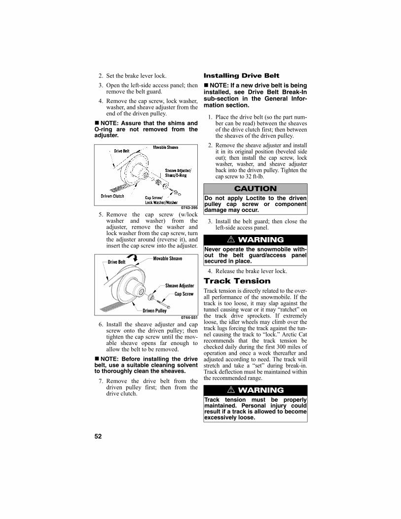
52
2. Set the brake lever lock.
3. Open the left-side access panel; thenremove the belt guard.
4. Remove the cap screw, lock washer,washer, and sheave adjuster from theend of the driven pulley.
NOTE: Assure that the shims andO-ring are not removed from theadjuster.
0743-395
5. Remove the cap screw (w/lockwasher and washer) from theadjuster, remove the washer andlock washer from the cap screw, turnthe adjuster around (reverse it), andinsert the cap screw into the adjuster.
0744-551
6. Install the sheave adjuster and capscrew onto the driven pulley; thentighten the cap screw until the mov-able sheave opens far enough toallow the belt to be removed.
NOTE: Before installing the drivebelt, use a suitable cleaning solventto thoroughly clean the sheaves.
7. Remove the drive belt from thedriven pulley first; then from thedrive clutch.
Installing Drive Belt
NOTE: If a new drive belt is beinginstalled, see Drive Belt Break-Insub-section in the General Infor-mation section.
1. Place the drive belt (so the part num-ber can be read) between the sheavesof the drive clutch first; then betweenthe sheaves of the driven pulley.
2. Remove the sheave adjuster and installit in its original position (beveled sideout); then install the cap screw, lockwasher, washer, and sheave adjusterback into the driven pulley. Tighten thecap screw to 32 ft-lb.
3. Install the belt guard; then close theleft-side access panel.
4. Release the brake lever lock.
Track TensionTrack tension is directly related to the over-all performance of the snowmobile. If thetrack is too loose, it may slap against thetunnel causing wear or it may “ratchet” onthe track drive sprockets. If extremelyloose, the idler wheels may climb over thetrack lugs forcing the track against the tun-nel causing the track to “lock.” Arctic Catrecommends that the track tension bechecked daily during the first 300 miles ofoperation and once a week thereafter andadjusted according to need. The track willstretch and take a “set” during break-in.Track deflection must be maintained withinthe recommended range.
CAUTIONDo not apply Loctite to the drivenpulley cap screw or componentdamage may occur.
! WARNINGNever operate the snowmobile with-out the belt guard/access panelsecured in place.
! WARNINGTrack tension must be properlymaintained. Personal injury couldresult if a track is allowed to becomeexcessively loose.

53
Checking Track Tension
1. Remove excess ice and snow buildupfrom the track, track drive sprockets,and the inside of the skid frame.
2. Elevate the snowmobile on ashielded safety stand high enough touse a spring scale.
3. At mid-point of the track (on thebottom side), hook a spring scalearound a track clip; then pull downon the scale to the recommendedpressure. Measure the deflection(distance) between the bottom of thewear strip and the inside surface ofthe track clip. Compare the measure-ment with the chart.
0743-188
Adjusting Track Tension
NOTE: To ensure proper track ten-sion adjustment, perform all adjust-ments on both sides of thesnowmobile.
1. Loosen the rear idler wheel adjust-ing bolt jam nuts.
739-636B
2. If the deflection (distance betweenthe bottom of the wear strip and theinside of the track) exceeds specifi-cations, tighten the adjusting bolts totake up excessive slack in the track.
3. If the distance between the bottom ofthe wear strip and the inside surfaceof the track is less than specified,loosen the adjusting bolts to increasethe slack in the track.
4. Check track alignment (see TrackAlignment sub-section in this sec-tion).
5. When proper track tension isobtained, tighten the adjusting boltjam nuts against the axle housings.
NOTE: Since track tension andtrack alignment are interrelated,always check both even if only oneadjustment seems necessary.
Track AlignmentProper track alignment is obtained whenthe rear idler wheels are equal distancefrom the inner track drive lugs. Excessivewear to the idler wheels, drive lugs, andtrack will occur if the track is improperlyaligned. Arctic Cat recommends that thetrack alignment be checked once a weekor whenever the track tension is adjusted.
! WARNINGDO NOT attempt to check or adjusttrack tension with engine running.Turn ignition key to the OFF position.Personal injury could result fromcontact with a rotating track.
Model Setup Tension
After Break-In Tension
All Models @ 20 lb 44-51 mm(1 3/4-2 in.)
51-57 mm(2-2 1/4 in.)
! WARNINGIf jam nuts are not tightened prop-erly, the adjusting bolts could loosencausing the track to becomeextremely loose and, under someoperating conditions, allow the idlerwheels to climb over the track lugsforcing the track against the tunnelcausing the track to “lock.” If a track“locks” during operation, severe per-sonal injury could result.

54
Checking Track Alignment
1. Remove excess ice and snow buildupfrom the track, track drive sprockets,and the inside of the skid frame.
2. Position the tips of the skis against awall; then using a shielded safetystand, raise the rear of the snowmo-bile off the floor making sure thetrack is free to rotate.
3. Start the engine and accelerateslightly. Use only enough throttle toturn the track several revolutions.SHUT ENGINE OFF.
NOTE: Allow the track to coast to astop. DO NOT apply the brakebecause it could produce an inaccu-rate alignment condition.
4. When the track stops rotating, checkthe relationship of the rear idlerwheels and the inner track drive lugs.If the rear idler wheels are centeredbetween the inner track drive lugs, noadjustment is necessary.
725-070A
5. If the idler wheels are not centeredbetween the inner track drive lugs,an adjustment is necessary.
Adjusting Track Alignment
1. On the side of the track which has theinner track drive lugs closer to therear idler wheel, loosen the adjustingbolt jam nut; then rotate the adjustingbolt clockwise 1 to 1 1/2 turns.
739-636B
2. Check track alignment and continueadjustment until proper alignment isobtained.
NOTE: Make sure correct tracktension is maintained after adjust-ing track alignment (see Track Ten-sion sub-section in this section).
3. After proper track alignment isobtained, tighten the adjusting boltjam nut against the axle housing.
4. Field test the track under actual con-ditions.
5. After the field test, check the align-ment of the track. If additional adjust-ment is necessary, repeat AdjustingTrack Alignment procedure.
SuspensionThe suspension should be adjusted forthe operational needs and riding prefer-ence of the operator.
! WARNINGMake sure the ignition key is in theOFF position and the track is notrotating before checking or adjustingtrack alignment. Personal injurycould result if contact is made with arotating track.
! WARNINGThe tips of the skis must be posi-tioned against a wall or similar object.
! WARNINGDO NOT stand behind the snowmo-bile or near the rotating track.NEVER run the track at high speedwhen the track is suspended.
! WARNINGIf a jam nut is not tightened properly,the adjusting bolt could loosen causingthe track to become dangerously loose.
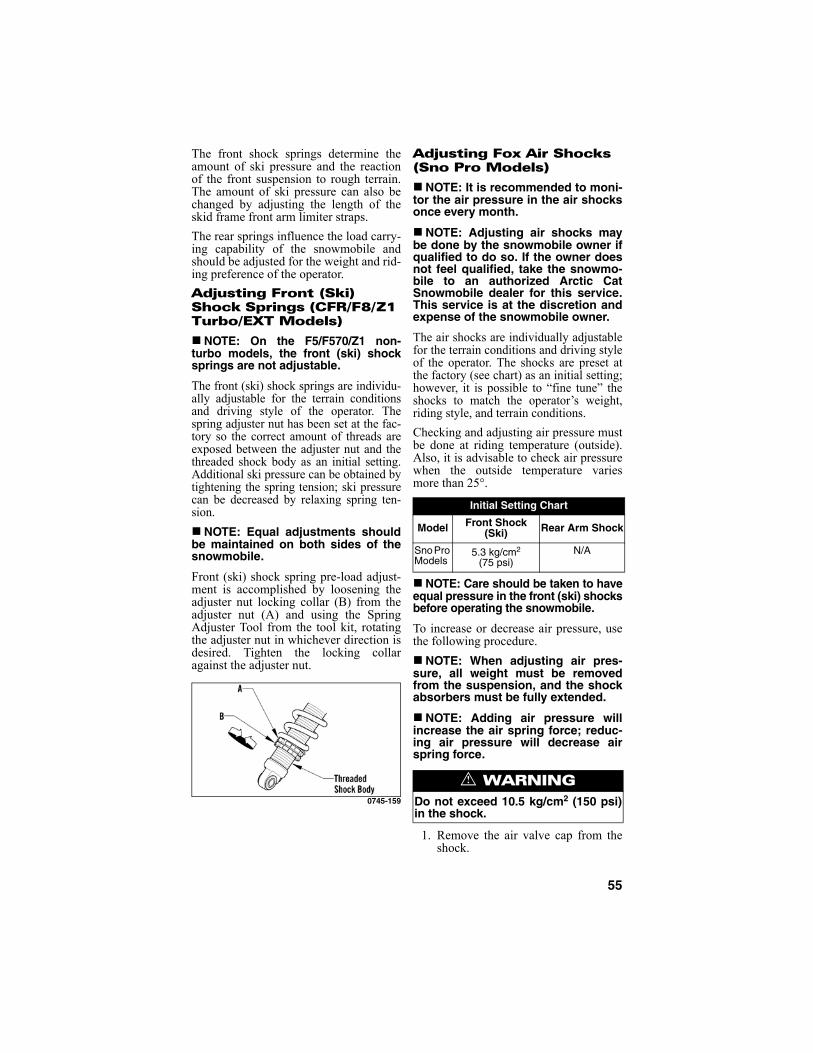
55
The front shock springs determine theamount of ski pressure and the reactionof the front suspension to rough terrain.The amount of ski pressure can also bechanged by adjusting the length of theskid frame front arm limiter straps.
The rear springs influence the load carry-ing capability of the snowmobile andshould be adjusted for the weight and rid-ing preference of the operator.
Adjusting Front (Ski) Shock Springs (CFR/F8/Z1 Turbo/EXT Models)
NOTE: On the F5/F570/Z1 non-turbo models, the front (ski) shocksprings are not adjustable.
The front (ski) shock springs are individu-ally adjustable for the terrain conditionsand driving style of the operator. Thespring adjuster nut has been set at the fac-tory so the correct amount of threads areexposed between the adjuster nut and thethreaded shock body as an initial setting.Additional ski pressure can be obtained bytightening the spring tension; ski pressurecan be decreased by relaxing spring ten-sion.
NOTE: Equal adjustments shouldbe maintained on both sides of thesnowmobile.
Front (ski) shock spring pre-load adjust-ment is accomplished by loosening theadjuster nut locking collar (B) from theadjuster nut (A) and using the SpringAdjuster Tool from the tool kit, rotatingthe adjuster nut in whichever direction isdesired. Tighten the locking collaragainst the adjuster nut.
0745-159
Adjusting Fox Air Shocks (Sno Pro Models)
NOTE: It is recommended to moni-tor the air pressure in the air shocksonce every month.
NOTE: Adjusting air shocks maybe done by the snowmobile owner ifqualified to do so. If the owner doesnot feel qualified, take the snowmo-bile to an authorized Arctic CatSnowmobile dealer for this service.This service is at the discretion andexpense of the snowmobile owner.
The air shocks are individually adjustablefor the terrain conditions and driving styleof the operator. The shocks are preset atthe factory (see chart) as an initial setting;however, it is possible to “fine tune” theshocks to match the operator’s weight,riding style, and terrain conditions.
Checking and adjusting air pressure mustbe done at riding temperature (outside).Also, it is advisable to check air pressurewhen the outside temperature variesmore than 25°.
NOTE: Care should be taken to haveequal pressure in the front (ski) shocksbefore operating the snowmobile.
To increase or decrease air pressure, usethe following procedure.
NOTE: When adjusting air pres-sure, all weight must be removedfrom the suspension, and the shockabsorbers must be fully extended.
NOTE: Adding air pressure willincrease the air spring force; reduc-ing air pressure will decrease airspring force.
1. Remove the air valve cap from theshock.
Initial Setting Chart
Model Front Shock (Ski) Rear Arm Shock
Sno Pro Models
5.3 kg/cm2
(75 psi)N/A
! WARNINGDo not exceed 10.5 kg/cm2 (150 psi)in the shock.

56
2. Thread the valve of Shock AbsorberAir Pump (p/n 2603-614) onto theshock air valve approximately sixrotations.
NOTE: As the pump is being attachedto the shock, the hose will fill with air.This will result in a lower gauge pres-sure 0.14-3.52 kg/cm2 (2-5 psi).
3. To decrease air pressure in theshock, press the black bleed valvebutton half way down and hold untildesired pressure is attained.
NOTE: Pressing the button fullydown and releasing it will allow onlya small amount of air to escape(micro-adjust).
4. To increase air pressure in the shock,pump until desired pressure isattained.
5. Remove the pump valve from theshock air valve.
NOTE: As the pump valve is beingremoved from the shock, the soundof air loss is from the pump hose,not from the shock.
6. Install the air valve cap onto theshock.
Adjusting Skid Frame Front Arm
NOTE: On the F5/F570/Z1 non-turbo models, the front arm shockspring is not adjustable.
The skid frame front arm shock spring ten-sion and the limiter straps are adjustable.However, Arctic Cat recommends that theshock spring be maintained at the factorypreset of 1/8-1/4 in. preload. Tighteningthe skid frame front arm shock spring maycause improper balance and may ruin thehandling features of the snowmobile.
The length adjustment of the front armlimiter straps determines the weight dis-tribution between the front of the skidframe and the skis. Tightening the limiterstrap (shortening the strap) will pull upon the front of the skid frame and willincrease ski pressure. Loosening the lim-iter strap (lengthening the strap) lowersthe front of the skid frame and decreasesski pressure.
When customizing the amount of skipressure, be sure to adjust both strapsequally and do not over-adjust the limiterstraps to adversely affect steering andoperator control of the snowmobile.Some experimentation may be requireduntil the proper adjustment for the opera-tor’s individual style is obtained.
NOTE: If the limiter straps areadjusted, it is highly recommendedthat at least a minimum of 1/8 in. pre-load on the shock spring be main-tained.
Adjusting Rear Spring Pre-Load
Proper adjustment of rear spring pre-loadis necessary to get the most desirableride. The chart is designed to help in set-ting up rear spring pre-load; however,riding style is the single greatest factor indetermining rear spring requirements.
NOTE: These cam position set-tings are suggestions only. Personalriding style will greatly influencecam position settings. Spend time todetermine setting preferences.
Rear spring pre-load adjustment isaccomplished by rotating the adjustingcams. Position 3 provides the stiffestride, and position 1 is for the light driveror slow-speed trail riding. Position 2 isfor the average operator under normalconditions. Always rotate the cam fromthe lighter position to the heavier posi-tion.
! WARNINGDo not adjust the front arm limiterstraps to a point at which steeringand operator control of the snowmo-bile are adversely affected.
Rider Weight (lb) Cam Position
Up to 180 1
180-240 2
Over 240 3
CAUTIONNever force the adjustment camsfrom the low position to the highposition. Cam damage may occur.

57
741-450A
To rotate an adjusting cam, use the sparkplug wrench from the tool kit. Rotate thewrench until the cam is in the desiredposition. To stiffen the ride, rotate the camso as to raise the spring end. Make theappropriate adjustment on the other cam.
LightsFor the correct headlight bulb and/or tail-light/brakelight LED, see the appropriatespecifications sheet.
Removing and Installing Taillight/Brakelight
These models are equipped with an LEDtaillight/brakelight. If the LED fails, itmust be replaced. To remove and installthe LED, use the following procedure.
NOTE: To access the harness con-nector and the two self-tappingscrews securing the taillight to thesnowflap, compress the two flangedtabs (located on the under-side ofthe tunnel) and carefully pry up onthe front of the taillight/snowflap.
0744-462
1. Disconnect the taillight harness con-nector.
2. Remove the two self-tapping screwssecuring the taillight to the snowflap.
3. Secure the taillight to the snowflapwith the two self-tapping screws;then connect the taillight connector.
4. Secure the front of the snowflap tothe tunnel by carefully tapping thesnowflap until the two flanged tabssnap into place.
Removing Headlight Bulb (CFR Models)
NOTE: The bulb portion of headlightis fragile. HANDLE WITH CARE. Whenreplacing the headlight bulb, the bulbassembly must first be removed fromthe housing. Do not touch the glassportion of the bulb. If the glass istouched, it must be cleaned with a drycloth before installing.
To access the headlight bulbs, use the fol-lowing procedure:
1. With the hood closed, loosen theheadlight adjustment knobs.
2. Carefully push the headlight lensesrearward far enough to remove thetorx-head screws securing the airsilencer plenum to the hood.
3. Open the hood; then remove the O-rings securing the air silencer ple-num to the hood and remove the airsilencer plenum to access the bulbs.
4. Remove the bulb from the headlighthousing and disconnect the wiringharness from the bulb.
0740-462
Installing Headlight Bulb (CFR Models)
1. Plug the wiring harness into theheadlight bulb.
CAUTIONDo not touch the glass portion of thebulb. If the glass portion is touched,it must be cleaned with a dry clothbefore installing.

58
2. Insert the bulb into the headlighthousing.
3. Press the air silencer plenum intoplace on the hood and secure withthe O-rings; then close the hood.
4. Carefully push the headlight lensesrearward far enough to install thetorx-head screws. Tighten thescrews securely.
5. Tighten the headlight adjustmentknobs.
6. Check headlight aim (see AdjustingHeadlight Aim in this sub-section).
Removing Headlight Bulb (F-Series/Z1/Z1 Turbo Models)
NOTE: The bulb portion of head-light is fragile. HANDLE WITH CARE.When replacing the headlight bulb,the bulb assembly must first beremoved from the housing. Do nottouch the glass portion of the bulb. Ifthe glass is touched, it must becleaned with a dry cloth beforeinstalling.
To access the headlight bulbs, use the fol-lowing procedure:
1. Remove the two torx-head screwslocated to the outside of the head-light adjustment knobs; then removethe single torx-head screw frombeneath the console (locatedbetween the headlights).
743-439A
2. Remove the cap screw and lock nutsecuring the front of the headlightassembly to the air-intake silencer.
3. Lift the front of the console enoughto allow the headlight housing to beremoved; then remove the housing.
4. Remove the bulb from the headlighthousing and disconnect the wiringharness from the bulb.
741-329A
Installing Headlight Bulb (F-Series/Z1/Z1 Turbo Models)
1. Plug the wiring harness into theheadlight bulb.
2. Insert the bulb into the headlighthousing.
3. Lift the front of the console enoughto allow the headlight housing to beinstalled; then install the housingmaking sure the forks of the housinggo into the grommets on top of theair-intake silencer. Secure with thecap screw and lock nut.
743-439A
! WARNINGDo not operate the snowmobileunless headlight beam is adjustedproperly. An incorrectly adjustedbeam will not provide the operatorthe optimum amount of light.
CAUTIONDo not touch the glass portion of thebulb. If the glass portion is touched,it must be cleaned with a dry clothbefore installing.

59
4. Position the console onto the air-intake silencer; then secure with thesingle torx-head screw beneath theconsole (located between the head-lights).
5. Install the two torx-head screwslocated to the outside of the head-light adjustment knobs; then tightensecurely.
6. Check headlight aim (see AdjustingHeadlight Aim in this sub-section).
Adjusting Headlight Aim
The headlight can be adjusted for verticalaim of the HIGH/LOW beam. The geo-metric center of HIGH beam zone is to beused for vertical aiming.
1. Position the snowmobile on a levelfloor so the headlight is approxi-mately 8 m (25 ft) from an aimingsurface (wall or similar surface).
NOTE: There should be an “aver-age” operating load on the snowmo-bile when adjusting headlight aim.
2. Measure the distance from the floorto midpoint of the headlight.
3. Using the measurement obtained instep 2, make a horizontal mark onthe aiming surface.
4. Make a vertical mark which inter-sects the horizontal mark on the aim-ing surface directly in front of theheadlight.
5. Engage the brake lever lock and startthe engine. Move the headlight dim-mer switch to the HIGH beam posi-tion. DO NOT USE LOW BEAM.
6. Observe the headlight beam aim.Proper aim is when the most intensebeam is centered on the vertical mark5 cm (2 in.) below the horizontalmark on the aiming surface.
0741-448
7. Adjust the headlight using theadjustment knobs until correct aim isobtained. Shut the engine off; thendisengage the brake lever lock.
Ski Wear BarsThe ski wear bar is a replaceable barattached to the underside of the ski. Thepurpose of the wear bar is to assist inturning the snowmobile, to minimize skiwear, and to maintain good steering con-trol. If the snowmobile is operated pri-marily in deep snow, ski wear bar wearwill be minimal; however, if the snow-mobile is operated on terrain where thesnow cover is minimal, the ski wear barwill wear faster. To maintain positivesteering characteristics, Arctic Cat rec-ommends that the ski wear bars bechecked before each use and replaced ifworn beyond 1/2 of the original diameter.Ski wear bars are available from anauthorized Arctic Cat Snowmobiledealer.
Removing Ski Wear Bars
NOTE: Determine which type ofwear bar is being replaced andremove and install accordingly.
1. Remove ice and snow buildup fromthe ski.
2. Using a suitable safety stand or lift,elevate the front of the snowmobile.
3. Remove the lock nuts securing thewear bar to the ski.
! WARNINGDo not operate the snowmobileunless headlight beam is adjustedproperly. An incorrectly adjustedbeam will not provide the operatorthe optimum amount of light.
! WARNINGOperating the snowmobile withexcessively worn ski wear bars mayresult in a loss of steering control.
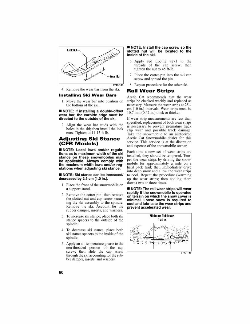
60
0743-185
4. Remove the wear bar from the ski.
Installing Ski Wear Bars
1. Move the wear bar into position onthe bottom of the ski.
NOTE: If installing a double-offsetwear bar, the carbide edge must bedirected to the outside of the ski.
2. Align the wear bar studs with theholes in the ski; then install the locknuts. Tighten to 11-15 ft-lb.
Adjusting Ski Stance (CFR Models)NOTE: Local laws and/or regula-tions as to maximum width of the skistance on these snowmobiles maybe applicable. Always comply withthe maximum width laws and/or reg-ulations when adjusting ski stance.
NOTE: Ski stance can be increased/decreased by 2.5 cm (1.0 in.).
1. Place the front of the snowmobile ona support stand.
2. Remove the cotter pin; then removethe slotted nut and cap screw secur-ing the ski assembly to the spindle.Remove the ski. Account for therubber damper, inserts, and washers.
3. To increase ski stance, place both skistance spacers to the outside of thespindle.
4. To decrease ski stance, place bothski stance spacers to the inside of thespindle.
5. Apply an all-temperature grease to thenon-threaded portion of the capscrew; then slide the cap screwthrough the ski accounting for the rub-ber damper, inserts, and washers.
NOTE: Install the cap screw so theslotted nut will be located to theinside of the ski.
6. Apply red Loctite #271 to thethreads of the cap screw; thentighten the nut to 45 ft-lb.
7. Place the cotter pin into the ski capscrew and spread the pin.
8. Repeat procedure for the other ski.
Rail Wear StripsArctic Cat recommends that the wearstrips be checked weekly and replaced asnecessary. Measure the wear strips at 25.4cm (10 in.) intervals. Wear strips must be10.7 mm (0.42 in.) thick or thicker.
If wear strip measurements are less thanspecified, replacement of both wear stripsis necessary to prevent premature trackclip wear and possible track damage.Take the snowmobile to an authorizedArctic Cat Snowmobile dealer for thisservice. This service is at the discretionand expense of the snowmobile owner.
Each time a new set of wear strips areinstalled, they should be tempered. Tem-per the wear strips by driving the snow-mobile for approximately a mile on ahard pack trail; then immediately driveinto deep snow and allow the wear stripsto cool. Repeat the procedure (warmingup the wear strips; then cooling themdown) two or three times.
NOTE: The rail wear strips will wearrapidly if the snowmobile is operatedon terrain on which the snow cover isminimal. Loose snow is required tocool and lubricate the wear strips andprevent accelerated wear.
0743-189

61
Performance TipsOperating a high performance snowmo-bile requires a special attention that is notrequired by a low performance snowmo-bile. Often, a minor adjustment willresult in a large increase in performance.This section is intended to highlightminor conditions that adversely affectperformance and the adjustments neededto correct them. Be sure, however, tothoroughly read and understand thisentire manual especially the section onspark plugs, track tension and alignment,and suspension.
DRIVE BELT — This link between theengine and drive train is often the mostneglected component. The drive belt musthave the proper fit in the drive clutch anddriven pulley. Proper fit is when the topsurface of the drive belt is flush with thetop or up to 1/16 in. higher than the drivenpulley sheaves (with the sheaves fullyclosed). If drive belt deflection is abovespecification, the snowmobile will bog andlack power at engagement and will have aslower maximum speed. For good perfor-mance, proper belt deflection is critical. Tocorrect this condition, first determine if thedrive belt is within specifications (seeDrive Belt sub-section) and replace ifworn or too long. Always run the drivebelt in the same direction. Installing thedrive belt so the part number can be readwill ensure that the drive belt is alwaysrun the same direction.
DRIVE BELT DEFLECTION — Drivebelt length, condition, and deflection areall important for peak performance. Tocheck and adjust drive belt deflection,remove the belt guard; then use the fol-lowing procedure.
NOTE: It may be necessary toremove a shim washer from betweenthe driven pulley sheaves to allow thedriven pulley to close tighter. Addingshim washers will decrease beltdeflection and removing shim wash-ers will increase belt deflection. Avail-able shim washers from Arctic Cat arep/n 0648-714 (0.090 in.) - one includedin the tool kit, p/n 0648-715 (0.030 in.),and p/n 0648-716 (0.060 in.).
NOTE: Removing/adding shimwashers may be done by the snow-mobile owner if qualified to do so. Ifthe owner does not feel qualified,take the snowmobile to an autho-rized Arctic Cat Snowmobile dealerfor this service. This service is at thediscretion and expense of the snow-mobile owner.
1. Turn the engine off; then open theaccess panel.
2. Make sure the drive belt is sitting atthe top of the driven pulley sheaves.
3. Place a straightedge on top of thedrive belt. The straightedge shouldreach from the driven clutch to thetop of the driven pulley.
4. Using a stiff ruler centered betweenthe drive clutch and driven pulley,push down on the drive belt justenough to remove all slack. Note theamount of deflection on the ruler atthe bottom of the straightedge. Thedeflection should be at 1 1/4 in.
0743-319
NOTE: Push down on the belt withthe ruler only until the bottom of thebelt flexes upward; then read theamount of deflection.
5. To correct drive belt deflection,remove the sheave adjuster from thepulley, remove or add shim washersto the adjuster, and install theadjuster.
NOTE: Adding shim washers willdecrease belt deflection; removingshim washers will increase beltdeflection.
6. Install the belt guard; then close theaccess panel.

62
DRIVE CLUTCH AND DRIVENPULLEY — Keeping the drive clutchand driven pulley clean should be the pri-mary consideration of the operator. Thedrive clutch and driven pulley can becleaned of any drive belt accumulationusing compressed air. The sheaves can becleaned using a clean cloth and parts-cleaning solvent.
DRIVE CLUTCH/DRIVEN PULLEYOFFSET — If premature drive belt wearis experienced or if the drive belt turnsover, offset must be checked. Also, offsetmust be checked whenever either thedrive clutch or driven pulley is serviced.
NOTE: For checking offset, it isnecessary to use Clutch AlignmentBar (p/n 0644-496). This special toolcan be purchased from an autho-rized Arctic Cat snowmobile dealer.
To check offset, use the following proce-dure.
1. Open the left-side access panel; thenremove the belt guard.
2. Install the clutch alignment barbetween the drive clutch sheaves.
3. Allow the bar to rest on the driveclutch shaft and against the outsideedge of the driven pulley stationarysheave.
NOTE: The alignment bar mustextend beyond the front edge of thedrive clutch.
4. With the bar against the outside edgeof the driven pulley stationarysheave at points A and B, the barshould just clear the inside edge ofthe stationary sheave of the driveclutch and rest on the stationaryshaft at point C with a maximum0.060 in. clearance at point C. Atthis point, measurement betweenpoints A and C should be 1.507 in.(with a maximum 0.060 in. clear-ance). If the bar either will not clearthe inside edge or is more than thespecified amount, the offset must becorrected.
0745-177
NOTE: If the offset is out of speci-fication, take the snowmobile to anauthorized Arctic Cat Snowmobiledealer for drive system evaluationand/or servicing. This service is atthe discretion and expense of thesnowmobile owner.
DRIVE CLUTCH/DRIVEN PULLEYPARALLELISM — If premature drivebelt wear is experienced or if the drivebelt turns over, parallelism must bechecked. Also, parallelism must bechecked whenever either the drive clutchor driven pulley is serviced.
NOTE: For checking parallelism, itis necessary to use Clutch Align-ment Bar (p/n 0644-509). This specialtool can be purchased from anauthorized Arctic Cat Snowmobiledealer.
To check parallelism, use the followingprocedure.
1. Remove the drive belt; then open thedriven sheaves and place clutchalignment bar between the sheaves.Release the sheaves.
2. Check the parallelism of the driveclutch/driven pulley using the paral-lelism bar and reference points Xand Y with the parallelism barbetween the driven sheaves. Using acaliper or a machinist’s scale, mea-sure X and Y from the back side ofthe parallelism bar to the back sideof the drive clutch sheave. Measure-ment Y must be 0.060 in. ± 0.020 in.more than measurement X, but Ymust not exceed measurement X bymore than 0.100 in.

63
0744-609
3. If parallelism is not within specifica-tions, the parallelism must be cor-rected by first loosening all theengine mounting bolts (left side,front, and right top rear). Then, prythe front of the engine towards theMAG-side of the engine compart-ment. Next tighten the left-sidemounting bolts followed by the frontand right-top rear bolts. Re-checkthe parallelism. If still out of specifi-cation, repeat correction procedure.
CARBURETOR MAIN JETS(F570 Model) — Proper carburetion isabsolutely necessary to obtain peak per-formance. Since ambient temperature andoperating altitude both affect the main jetsize needed for optimum engine perfor-mance, the main jets MUST be changedwhenever the temperature changes 20° For whenever operating altitude varies bymore than 1000 feet. The Carburetor JetChart on the belt guard of the snowmo-bile identifies the proper main jets to useunder all operating temperatures and alti-tudes. Follow the Carburetor Jet Chartcarefully to obtain peak engine perfor-mance and avoid engine damage.
GASOLINE — On the CFR 1000/F570/F5/F6 models for optimum performance,it is not necessary to exceed the recom-mended 87 octane gasoline. Using ahigher octane gasoline will not increaseoverall performance. It is recommendedthat 91 octane (minimum) gasoline beused in the CFR 800/F8 models.
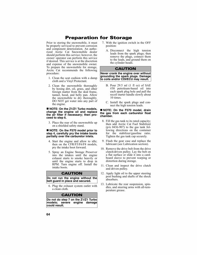
64
Preparation for StoragePrior to storing the snowmobile, it mustbe properly serviced to prevent corrosionand component deterioration. An autho-rized Arctic Cat Snowmobile dealershould perform this service; however, theowner/ operator can perform this serviceif desired. This service is at the discretionand expense of the snowmobile owner.To prepare the snowmobile for storage,Arctic Cat recommends the followingprocedure:
1. Clean the seat cushion with a dampcloth and a Vinyl Protectant.
2. Clean the snowmobile thoroughlyby hosing dirt, oil, grass, and otherforeign matter from the skid frame,tunnel, hood, and belly pan. Allowthe snowmobile to dry thoroughly.DO NOT get water into any part ofthe engine.
NOTE: On the Z1/Z1 Turbo models,change the engine oil and replacethe air filter if necessary; then pro-ceed to step 6.
3. Place the rear of the snowmobile upon a shielded safety stand.
NOTE: On the F570 model prior tostep 4, carefully pry the intake bootspartially over the carburetor inlets.
4. Start the engine and allow to idle;then on the CFR/F5/F6/F8 models,pry the intake boot forward.
5. Spray an Engine Storage Preserverinto the intakes until the engineexhaust starts to smoke heavily oruntil the engine starts to drop inRPM. Turn engine off. Install theintake boots.
6. Plug the exhaust system outlet witha clean cloth.
7. With the ignition switch in the OFFposition:
A. Disconnect the high tensionleads from the spark plugs; thenremove the plugs, connect themto the leads, and ground them onthe cylinder heads.
B. Pour 29.5 ml (1 fl oz) of SAE#30 petroleum-based oil intoeach spark plug hole and pull therecoil starter handle slowly about10 times.
C. Install the spark plugs and con-nect the high tension leads.
NOTE: On the F570 model, drainthe gas from each carburetor floatchamber.
8. Fill the gas tank to its rated capacity;then add Arctic Cat Fuel Stabilizer(p/n 0436-907) to the gas tank fol-lowing directions on the containerfor the stabilizer/gasoline ratio.Tighten the gas tank cap securely.
9. Flush the gear case and replace thelubricant (see Lubrication section).
10. Remove the drive belt from the driveclutch/driven pulley. Lay the belt ona flat surface or slide it into a card-board sleeve to prevent warping ordistortion during storage.
11. Clean and inspect the drive clutchand driven pulley.
12. Apply light oil to the upper steeringpost bushing and shafts of the shockabsorbers.
13. Lubricate the rear suspension, spin-dles, and steering arms with all-tem-perature grease.
CAUTIONDo not run the engine without thebelt guard in place and secured.
CAUTIONDo not do step 7 on the Z1/Z1 Turbomodels; severe engine damagecould result.
CAUTIONNever crank the engine over withoutgrounding the spark plugs. Damageto coils and/or CDI/ECU may result.
65
14. Tighten all nuts, bolts, and capscrews making sure all nuts, bolts,and cap screws are tightenedsecurely. Make sure all rivets hold-ing the components together aretight. Replace all loose rivets.
15. Clean and polish the hood, console,and chassis with Arctic Cat Hoodand Windshield Cleaner/ Polish (p/n4639-559). DO NOT USE SOL-VENTS OR SPRAY CLEANERS.THE PROPELLANT WILL DAM-AGE THE FINISH.
NOTE: On electric start models,disconnect the battery cables mak-ing sure to disconnect the negativecable first; then clean the batteryposts and cables. Charge the bat-tery.
16. If possible, store the snowmobileindoors. Raise the track off the floorby blocking up the back end makingsure the snowmobile is secure.Loosen the track adjusting bolts toreduce track tension. Cover thesnowmobile with a machine cover ora heavy tarpaulin to protect it fromdirt and dust.
17. If the snowmobile must be storedoutdoors, position the snowmobileout of direct sunlight; then block theentire snowmobile off the groundmaking sure the snowmobile issecure. Loosen the track adjustingbolts to reduce track tension. Coverwith a machine cover or a heavy tar-paulin to protect it from dirt, dust,and rain.
CAUTIONSealed batteries require charging ifleft for extended non-start periods.Arctic Cat recommends tricklecharging once a month. Follow themanufacturer’s instructions andcautions.
CAUTIONAvoid storing in direct sunlight andusing a plastic cover as moisturemay collect on the snowmobilecausing corrosion.

66
Preparation after StorageTaking the snowmobile out of storageand correctly preparing it for another sea-son will assure many miles and hours oftrouble-free snowmobiling. Arctic Catrecommends the following procedure:
1. Clean the snowmobile thoroughly.Polish the exterior of the snowmobile.
2. Clean the engine. Remove the clothfrom the exhaust system. Checkexhaust system and air-intakesilencer for obstructions.
3. Inspect all control wires and cablesfor signs of wear or fraying. Replaceif necessary. Use cable ties or tape toroute wires and cables away fromhot or rotating parts.
4. Inspect the drive belt for cracks andtears. Check belt specifications.Replace if damaged or worn. Installthe drive belt.
NOTE: If the old belt is worn but inreasonable condition, retain it withthe snowmobile as a spare in case ofemergency.
NOTE: On the F570 model, inspectthe in-line fuel filter and replace ifnecessary.
5. Inspect all fuel hoses and oil hosesfor deterioration or cracks; replace ifnecessary. Make sure all connectionsare tight; then on the CFR/F-Seriesmodels, fill the oil-injection reser-voir with the recommended 2-cycleoil (see Gasoline-Oil - Recom-mended Injection Oil sub-section inthe General Information section).
NOTE: After prolonged storage ofthe CFR/F-Series models, Arctic Catrecommends one tankful of 100:1gas/oil mixture be used in conjunc-tion with the oil-injection system toensure proper lubrication.
6. On the F-Series models,inspect thespark plugs. Replace, gap, or cleanas necessary.
7. Verify the condition of and theadjustment of the carburetors andchoke cable (on the F570 model)and throttle cable (on all models).
8. Tighten all nuts, bolts, and capscrews making sure all nuts, bolts,and cap screws are tightenedsecurely.
9. If not done during preparation forstorage, lubricate the rear suspen-sion, spindles, and steering armswith all-temperature grease.
10. On the liquid-cooled models,check the coolant level and all cool-ant hoses and connections for deteri-oration or cracks. Add properlymixed coolant as necessary.
11. On the F570 model, clean theengine cooling fins and vents.
12. On electric start models, charge thebattery until fully charged (see Bat-tery sub-section in the Maintenancesection); then connect the batterycables making sure to connect thepositive cable first. Test the electricstart system.
13. Inspect the entire brake system, allcontrols, headlight, taillight, brake-light, ski wear bars, and headlightaim; adjust or replace as necessary.
14. Adjust the track to the proper ten-sion and alignment (see Track Ten-sion and Track Alignment sub-sections in the Maintenance sec-tion).
CAUTIONOn the F570 model if the gas in eachcarburetor float chamber was notdrained prior to storage, the carbu-retors must be cleaned before start-ing the engine.
! WARNINGOn the F570 model, be sure totighten the swivel adapter jam nutssecurely. If a jam nut isn’t tightened,the adjuster can rotate out of the car-buretor cap causing the throttlevalve not to return to the full-closedposition.

67
NOTES

68
U.S. EPA Emission Control Statement/Warranty Coverage (U.S. Only)
STATEMENT/WARRANTYArctic Cat warrants to the original retail purchaser, and each subsequent purchaser, that all U.S. EPA-certified Arctic Cat snowmobiles are designed, built, and equipped to conform to all U.S. EPA EmissionControl Regulations. Please read the following information completely.
Your authorized Arctic Cat snowmobile dealer will repair or replace any defective emission-relatedcomponent at no cost to you during the warranty period. You may have non-warranty service performedby any repair establishment that uses equivalent components. The regulations provide significant civilpenalties for tampering that causes your snowmobile to no longer meet U.S. EPA emission standards.
Arctic Cat further warrants that the engine and its emission-related components are free from defects inmaterials or workmanship that could cause the engine to fail to comply with applicable regulationsduring the warranty period.
If you have any questions about this information, or the emission warranty coverage statement, contactyour local authorized Arctic Cat snowmobile dealer.
WARRANTY PERIODThe emission warranty period for this snowmobile begins on the same date as the standard warrantycoverage and continues for 30 months or 2500 miles, whichever comes first.
COMPONENTS COVEREDThe emissions warranty covers major emissions control components and emission-related componentslisted as follows:
Engine Management and Sensors Fuel/Air SystemBarometric Pressure Sensor Fuel InjectorsCamshaft Position Sensor Fuel Pressure RegulatorEngine Control Unit (ECU) Fuel PumpEngine Coolant Temperature Sensor Carburetor(s)Intake Air Temperature Sensor Turbocharger AssemblyManifold Absolute Pressure Sensor Air Bypass ValveOxygen Sensor Turbo Waste Gate Control ValveThrottle Position Sensor Crankcase Ventilation System
ISC Valve
Ignition System Miscellaneous Items Used in Aforementioned Systems
Ignition Coil ConnectorsKnock Sensor System SwitchesCrankshaft Position Sensor GrommetsExhaust Temperature Sensor ClampsCapacitive Discharge Ignition (CDI) Module HosesMagneto Pick-Up Ties
GasketsWiring
OWNER'S RESPONSIBILITIESThe owner of any snowmobile warranted under this Arctic Cat Emission Control Statement isresponsible for the proper maintenance and use of the snowmobile as stated in the Operator's Manual.Proper maintenance generally includes replacement and service, at the owner's choosing, such itemsas air filter, oil and oil filter, or any other part, item, or device related to emissions control as specified inthe Operator's Manual. It is the owner's responsibility to ensure that the snowmobile is used in a mannerfor which it was designed.

69
Change of Address, Ownership, or Warranty Transfer
Arctic Cat Inc. keeps on file the current name and address of theowner of this snowmobile. This will allow Arctic Cat to reach thecurrent owner with any important safety information which maybe necessary to protect customers from personal injury orproperty damage. Please make sure a copy of this form iscompleted and returned to Arctic Cat Inc. if you move or if thesnowmobile is sold to another party.
This form may also be used to transfer the unused portion of theoriginal warranty to a second party. In order to transfer warranty,fill out this form completely; then return a copy of this form toArctic Cat Inc. Arctic Cat will then process the application andissue warranty for the balance of the time remaining of theoriginal warranty.
Address Change
Ownership Change
Warranty Transfer
CHANGE OF ADDRESS/OWNERSHIP/WARRANTY TRANSFER TO:
Name ________________________________________
Address ______________________________________
City/State (Province)/Zip Code (Postal Code) __________
Phone # ( ) __________________________________
Year and Model Snowmobile ______________________
Vehicle Identification Number (VIN) _________________
Fold Back Once
CHANGE OF ADDRESS/OWNERSHIP
ARCTIC CAT INC.PRODUCT SERVICE AND
WARRANTY DEPT.P.O. BOX 810
THIEF RIVER FALLS, MN 56701
PlaceStampHere

Warranty Procedure/Owner Responsibility
At the time of sale, an Owner Registration form is to be completed by the sellingdealer and consumer. The receipt of the registration form by Arctic Cat is a condi-tion precedent to warranty coverage. It is the selling dealer’s responsibility to retainand/or submit the appropriate copies of the form to the appropriate place(s) to initi-ate warranty coverage.
The dealer will furnish to the consumer a signed copy of the form which must bepresented to the dealer when requesting warranty service. The registration form isthe consumer’s proof of ownership and warranty eligibility. The form is usedby the dealer to validate the warranty claim. Retain your copy of the form andkeep it in a safe place.
When warranty repair is suspected, the snowmobile should be taken to the sellingdealer, who has the primary responsibility to perform warranty repairs. Subject tothe limitations set forth in the Limited Warranty, in the event the selling dealer hasceased to do business, you have moved, or you are in a location away from yourselling dealer, warranty may be performed by any authorized Arctic Cat Snowmo-bile dealer.
The authorized Arctic Cat Snowmobile dealer will examine the snowmobile or partto determine if, in his opinion, a warrantable condition exists. If a warrantable con-dition appears to exist, the dealer will repair or replace, at Arctic Cat’s option, freeof charge, including any related labor costs, all parts that are found to be warrant-able and any other parts which the warrantable part caused to be damaged. You, theconsumer, will then be asked to sign a warranty form to ensure Arctic Cat that thewarranty work was actually performed.
It is the consumer’s responsibility to maintain and service the snowmobile in accor-dance with Arctic Cat’s recommendations in the Operator’s Manual. To protectyourself and your snowmobile, follow all safety and service tips. Arctic Cat willNOT warrant repairs required as a result of not performing standard operatormaintenance, storage procedures, and service as outlined in the Operator’sManual.
Should you have any questions concerning the warranty, contact an authorized Arc-tic Cat Snowmobile dealer.
Arctic Cat Inc., P.O. Box 810, Thief River Falls, MN 56701 (218) 681-8558
Printed in U.S.A. Trademarks of Arctic Cat Inc. Thief River Falls, MN 56701 p/n 2258-796Phone: (218) 681-9851 - U.S./(204) 982-1656 - Canada
®TM
ARCTIC CAT®