performance investigation and multi-objective …umpir.ump.edu.my/13160/1/fkm - syeda najiha masood...
TRANSCRIPT

PERFORMANCE INVESTIGATION AND MULTI-OBJECTIVE OPTIMIZATION
OF END MILLING OF ALUMINIUM ALLOY 6061 T6 WITH COATED AND
UNCOATED CARBIDE TOOLS UNDER VARIOUS COOLING CONDITIONS
SYEDA NAJIHA MASOOD
Thesis submitted in fulfilment of the requirements
for the award of the degree of
Doctor of Philosophy in Mechanical Engineering
Faculty of Mechanical Engineering
UNIVERSITI MALAYSIA PAHANG
November 2015

vi
ABSTRACT
Application of cutting fluids as cooling and lubricating media is considered essential in
manufacturing practices on account of providing lubrication, heat transfer capabilities,
corrosion minimization as well as flushing away of metal chips and debris. On account
of sizable costs, increasing eco-awareness, implementation of sustainability indices in
manufacturing units and strict regulations due to detrimental effects of cutting fluids to
the environment and the human exposure, economically viable substitutes to cutting
fluids are being explored. Minimum quantity lubrication (MQL) technique offers a near-
term solution to the problem. The objectives of this study are to investigate the machining
performance and to develop multi-objective optimization model in end milling of
aluminium alloy AA6061-T6 with conventional MQL and nanofluid-MQL techniques.
Uncoated tungsten carbide (WC-Co 6.0%) and PVD TiAlN and TiAlN+TiN coated
carbide cutting tools are considered using 23.4-54.0 ml/hr flow rate of commercial
mineral oil for MQL machining with different combinations of input cutting parameters.
Nanofluid % volume fraction is varied from 0.5 %-4.5 %. Response surface methodology
(RSM) with central composite design approach is used for the design of experiments.
Second order mathematical models are developed for machining performance measures
with different cooling conditions and validated statistically. The developed models show
good agreement (< 5 % error) with the experimental results. PVD coated carbide tools
outperformed uncoated tool in terms of tool damage and surface quality and uncoated
tool is selected for the nanofluid MQL machining. The effectiveness of MQL is compared
with conventional flooded conditions. Nanofluid-MQL exhibits superior performance
compared to flooded and conventional MQL in terms of surface roughness and tool wear.
For material removal rate results are almost similar in all cases. Tool damage is
characterized by SEM micrographs and EDX patterns. Adhesion, edge chipping and
coating damage for uncoated and coated tools are observed with higher feed rate, higher
depths of cut and lower MQL flow rate. The major benefit from the water-based nanofluid
MQL is shown in the edge integrity, which is attributed to the cooling effect produced
due to latent heat of vaporization of water. Experimental results show the prospective
utilization of water-based TiO2 nanofluid as MQL cooling medium. Comprehensive
multi-objective optimization model using genetic algorithm is developed to optimize
machining performance measures under different MQL conditions, based on Pareto
optimal design approach. As a result of optimization, the resultant improvements in
surface roughness and flank wear in conventional MQL machining for uncoated tungsten
carbide tool are 74.2 % and 58.4 %; for PVD TiAlN coated tools are 16.9 % and 73.6 %;
for PVD TiAlN+TiN coated tool are 60 % and 41.4 %, respectively. For nanofluid-MQL
machining, the optimum nanofluid volume concentration is 2.64 %. Promising results of
the study in terms of process performance, compared with traditional practices, highly
advocate the use of MQL technique with water-based nanofluid in industrial machining
application as well as academia activities.

vii
ABSTRAK
Aplikasi bendalir pemotong sebagai medium penyejukan dan pelinciran amat penting
dalam pembuatan yang melibatkan jumlah pelincir, kebolehtahanan pertukaran haba,
pengurangan karat dan juga pembuangan cip logam and minyak. Disebabkan oleh faktor
kos, peningkatan kesedaran-eco, perlaksanaan konsep kelestarian dalam unit pembuatan
dan peraturan yang ketat berkaitan dengan kesan bendalir pemotongan terhadap
persekitaran dan pendedahan kepada amanusia, secara ekonominya perlu diganti dan
bendalir pemotongan perlu dikaji. Kaedah pelinciran kuantiti minimum (MQL)
menawarkan penyelesaian kepada masalah ini. Objektif kajian ini adalah menyiasat
persembahan pemesinan dan pembangunan model objektif optimum pelbagai dalam
proses pemesinan logam aluminium AA6061-T6 dengan menggunakan MQL
konvensional dan teknik MQL-bendalir-nano. Alatan pemotong tunsten karbida tanpa
salutan (WC-Co 6.0%) dan karbida bersalut PVD digunakan menggunakan kadar aliran
23.4-54.0 ml/hr minyak mineral komersial untuk pemesianan MQL dengan kepelbagaian
parameter masukan pemesinan. Jumlah peratusan pecahan bendalir nano dipelbagaikan
dari 0.5 hingga 4.5 %. Kaedah tindakan permukaan dengan pendekatan rekabentuk
komposit berpusat digunakan untuk rekabentuk eksperimen. Model matematik kedua
dibangunkan untuk mengukur persembahan pemesinan dengan keadaan pelbagai
penyejukan dan ditentushakan secara statistik. Model yang dibangunkan menunjukkan
persetujuan yang baik (ralat kurang 5 %) dengan keputusan eksperimen. Alatan PVD
bersalut karbida mengatasi persembahan alatan tidak bersalut pada kerosakan alat dan
kemasan permukaan, maka alatan tidak bersalut digunakan unutk pemesinan MQL
bendalir-nano. Keberkesanan MQL dibandingkan dengan keadaan keadaan
konvensioanal penyejukkan banjir. Bendalir-nano MQL menunjukkan persembahan
cemerlang berbanding dengan penyejukkan banjir dan konvensional MQL pada kemasan
permukaan dan kehausan alatan. Untuk kadar pembuangan bahan menunjukkan
keputusan yang sama bagi semua kes. Kerosakan alatan diselidiki dengan mikro geraf
SEM and corak EDM. Pelekatan, serpihan sisi dan kerosakan salutan untuk alatan
bersalut dan tidak bersalut diperhatikan pada kadar masukan yang tinggi dan kadar aliran
MQL yang rendah. Kelebihan yang besar diperolehi dari MQL bendalir nano berasaskan
air ditunjukkan pada integriti sisi, yang mana disebabkan oleh kesan penyejukkan yang
terhasil daripada pemeluapan haba laten air. Keputusan eksperimen menunjukkan
prospek penggunaan bendalir nano berasaskan air TiO2 sebagai medium penyejukan
MQL. Model objektif optimum pelbagai yang komprehensif menggunakan algoritma
genetik dibangunkan untuk mengoptimumkan persembahan pemesinan diukur pada
kelainan keadaan MQL, berasaskan kaedaan optimal rekabentuk Pareto. Hasil keputusan
pengoptimuman, menunjukkan penambahan kemasan permukaan dan kehausan rusuk
pada pemesinan konvensional MQL untuk alatan karbida tunsten yang tidak bersalut
adalah 74.2 % dan 58.4 %; untuk alatan bersalut PVD TiAlN adalah 16.9 % dan 73.6 %;
untuk alatan bersalut PVD TiAlN+TiN masing-masing adalah 60 % dan 41.4 %. Untuk
pemesinan bendalir nano MQL, kepekatan isipadu bendalir nano yang optimum adalah
2.64 %. Harapan keputusan daripada kajian ini dalam persembahan proses, berbanding
dengan praktikal tradisional, penggunaan kaedah MQL dengan bendalir nano berasaskan
air sangat dicadangkan dalam industri aplikasi pemesinan dan juga aktiviti-aktiviti
akademik.

viii
TABLE OF CONTENTS
Page
SUPERVISOR’S DECLARATION ii
STUDENT’S DECLARATION iii
DEDICATION iv
ACKNOWLEDGEMENTS v
ABSTRACT vi
ABSTRAK vii
TABLE OF CONTENTS viii
LIST OF TABLES xii
LIST OF FIGURES xv
LIST OF SYMBOLS xxii
LIST OF ABBREVIATIONS xxv
CHAPTER 1 INTRODUCTION
1.1 Introduction 1
1.2 Problem Statement 3
1.3 Objectives of the Study 6
1.4 Scope of the Study 6
1.5 Organization of Thesis 7
CHAPTER 2 LITERATURE REVIEW
2.1 Introduction 8
2.2 Cutting Fluids in Sustainable Manufacturing 8
2.3 Sustainable Machining Systems 10
2.3.1 Dry Machining 12
2.3.2 High Pressure Coolant Technique 13
2.3.3 Solid Lubricant Technique 14
2.3.4 Air, Vapor and Gas Coolant 15
2.3.5 Cryogenic Coolants 16
2.3.6 Minimum Quantity Lubrication 17
2.4 Nanofluids 25

ix
2.4.1 Nanofluids as Coolants 26
2.4.2 Nanofluids as Lubricants 27
2.5 Properties of Nanofluids 28
2.5.1 Thermal Conductivity 28
2.5.2 Convective Heat Transfer Coefficient 28
2.5.3 Viscosity of Nanofluids 30
2.6 Nanofluids in Machining Applications 32
2.7 Multi-Objective Optimization in Machining 36
2.8 Tool Wear with Aluminium and Aluminium Alloys 39
2.9 Summary 43
CHAPTER 3 EXPERIMENTAL WORK AND OPTIMIZATION
MODELLING
3.1 Introduction 44
3.2 Flow Chart of the Study 44
3.3 Materials 45
3.3.1 Workpiece Material 45
3.3.2 Cutting Fluids 46
3.3.3 Cutting Tool and Inserts 48
3.4 Machining Parameters 50
3.4.1 Process Parameters 51
3.4.2 Performance Parameters 53
3.5 Experimental Details 58
3.5.1 Design of Experiments 58
3.5.2 Experimental Setup 60
3.5.3 MQL System 62
3.6 Mathematical Modelling 64
3.6.1 Model Development 64
3.6.2 Analysis of Variance 66
3.7 Preparation of Nanofluid 67
3.8 Properties of Nanofluid 69
3.8.1 Density 69
3.8.2 Thermal Conductivity Measurement 70
3.8.3 Viscosity and pH of TiO2 Nanofluid 71
3.9 Multi-Objective Optimization 72
3.9.1 Optimization Modelling 74
3.9.5 Optimization Algorithm 76

x
3.9.6 Multi-Criteria Decision Making 79
3.10 Modelling and Optimization Tools 80
3.11 Summary 81
CHAPTER 4 RESULTS AND DISCUSSION
4.1 Introduction 82
4.2 Mathematical Modelling 82
4.2.1 Material Removal Rate 83
4.2.2 Surface Roughness 90
4.2.3 Flank Wear 98
4.3 Confirmation Runs 99
4.4 Effects of Input Parameters on Response Variables 101
4.4.1 Material Removal Rate 102
4.4.2 Surface Roughness 107
4.4.3 Flank Wear 125
4.4.4 Wear Maps 144
4.5 Performance Comparison 151
4.6 Wear Mechanisms 154
4.6.1 Uncoated Tungsten Carbide Insert 154
4.6.2 TiAlN Coated Insert 163
4.6.3 TiAlN+TiN Coated Insert 172
4.6.4 Energy Dispersive X-Ray Analysis 182
4.7 Tool Wear for Nanofluid-MQL Conditions 187
4.8 Surface Roughness as a Measure of Flank Wear 213
4.9 Machining Performance of the Tools 216
4.10 Optimization Performance 218
4.10.1 Uncoated Tungsten Carbide Insert in Conventional MQL 218
4.10.2 TiAlN Coated Insert in Conventional MQL 221
4.10.3 TiAlN+TiN Coated Insert in Conventional MQL 224
4.10.4 Uncoated Tungsten Carbide Insert in Nanofluid-MQL 224
4.11 Selection of Best Solutions 228
4.12 Confirmation Runs for Optimization 229
4.13 Summary 230

xi
CHAPTER 5 CONCLUSIONS AND RECOMMENDATIONS
5.1 Introduction 232
5.2 Summary of Findings 232
5.2.1 Modelling of Machining Performance Measures 232
5.2.2 Performance Analysis 233
5.2.3 Optimization 235
5.3 Contributions of the Study 236
5.4 Recommendations for Future Work 237
REFERENCES 238
LIST OF PUBLICATIONS 264
APPENDICES
A1 Measured values of average surface roughness in flooded conditions
266
A2 Measured values of material removal rate (MRR) in flooded conditions
267
A3 Measured values of flank wear in flooded conditions
268
A4 Measured values of average surface roughness in conventional MQL
conditions
269
A5 Measured values of average surface roughness with uncoated carbide insert 270
in nanofluid MQL conditions
A6 Measured values of material removal rate in conventional MQL conditions
271
A7 Measured values of material removal rate with uncoated carbide insert in 272
nanofluid-MQL conditions
A8 Measured values of flank wear in conventional MQL conditions
273
A9 Measured values of flank wear with uncoated carbide insert in nanofluid 274
MQL conditions

xii
LIST OF TABLES
Table No. Title Page
2.1 Thermal conductivity enhancement in TiO2–water nanofluids 29
2.2 Summary of convective heat transfer properties of nanofluids 31
2.3 Volume fraction dependent viscosity of nanofluids
31
3.1 The alloy composition of the AA6061-T6 46
3.2 Physical, thermal and mechanical properties of AA6061-T6 46
3.3 Composition, properties and dimensions of end mill inserts 49
3.4 Levels assigned to the input cutting parameters for flooded, 60
conventional MQL and nanofluid-MQL cooling
3.5 Specifications of the HAAS-VF6 vertical machining center 62
3.6 Measured values of viscosity and pH for different fractions of 72
nanofluid
3.7 Software tools used in the research 80
4.1 Estimated regression coefficients for material removal rate with 84
different cooling conditions for uncoated tungsten carbide insert
4.2 ANOVA for material removal rate with uncoated tungsten carbide 85
insert with different cooling conditions
4.3 Estimated regression coefficients for material removal rate with 86
different cooling conditions for TiAlN coated tungsten carbide
insert
4.4 ANOVA for material removal rate with TiAlN coated tungsten 87
carbide insert with different cooling conditions
4.5 Estimated regression coefficients for material removal rate with 88
different cooling conditions for TiAlN+TiN coated tungsten
carbide insert
4.6 ANOVA for material removal rate with TiAlN+TiN coated carbide 89
insert with different cooling conditions
xiii
Table No. Title Page
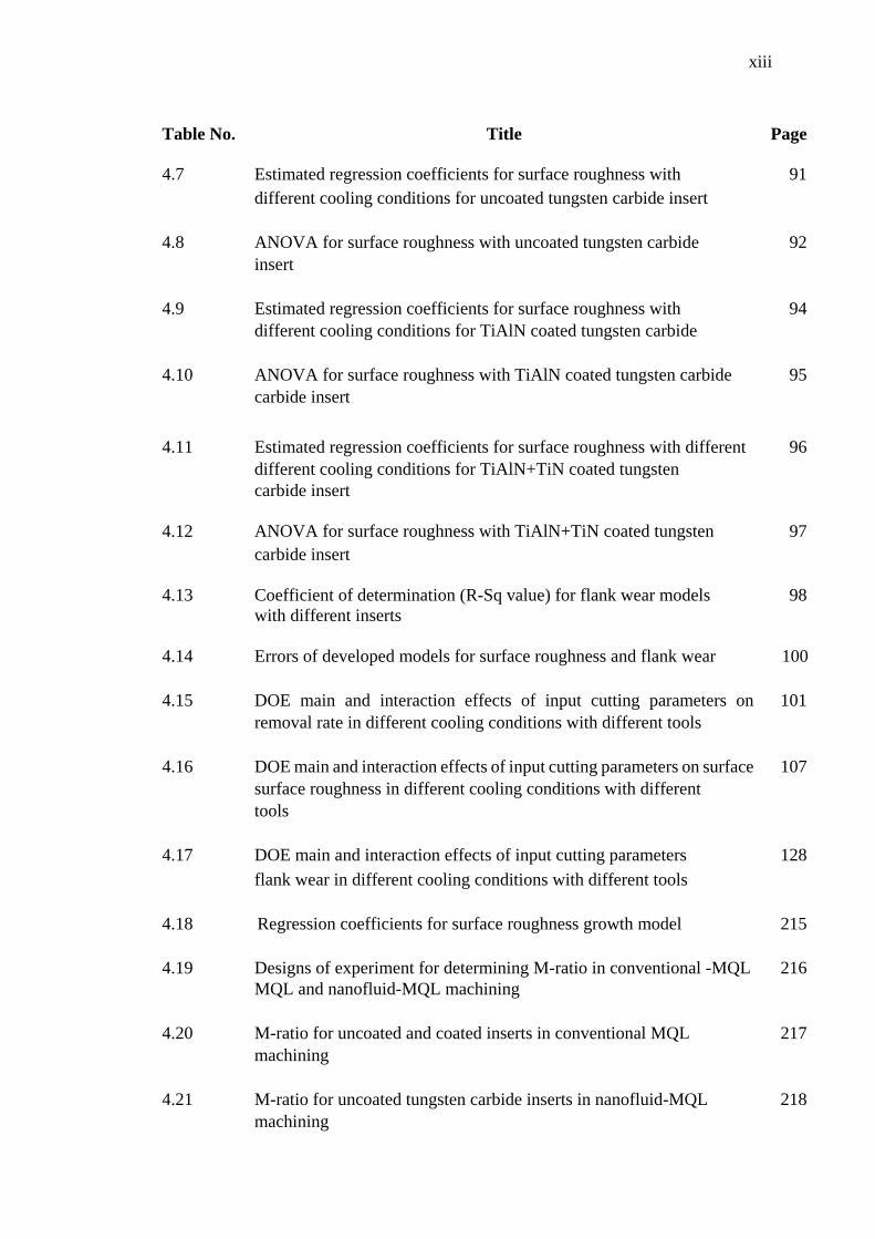
4.7 Estimated regression coefficients for surface roughness with 91
different cooling conditions for uncoated tungsten carbide insert
4.8 ANOVA for surface roughness with uncoated tungsten carbide 92
insert
4.9 Estimated regression coefficients for surface roughness with 94
different cooling conditions for TiAlN coated tungsten carbide
insert
4.10 ANOVA for surface roughness with TiAlN coated tungsten carbide
insert
95
carbide insert
4.11 Estimated regression coefficients for surface roughness with different
cooling conditions for TiAlN+TiN coated tungsten carbide insert
96
different cooling conditions for TiAlN+TiN coated tungsten
carbide insert
4.12 ANOVA for surface roughness with TiAlN+TiN coated tungsten 97
carbide insert
4.13 Coefficient of determination (R-Sq value) for flank wear models 98
with different inserts
4.14 Errors of developed models for surface roughness and flank wear 100
4.15 DOE main and interaction effects of input cutting parameters on
material
101
removal rate in different cooling conditions with different tools
4.16 DOE main and interaction effects of input cutting parameters on surface 107
surface roughness in different cooling conditions with different
tools
4.17 DOE main and interaction effects of input cutting parameters 128
flank wear in different cooling conditions with different tools
4.18 Regression coefficients for surface roughness growth model 215
4.19 Designs of experiment for determining M-ratio in conventional -MQL 216
MQL and nanofluid-MQL machining
4.20 M-ratio for uncoated and coated inserts in conventional MQL 217
machining
4.21 M-ratio for uncoated tungsten carbide inserts in nanofluid-MQL 218
machining
xiv
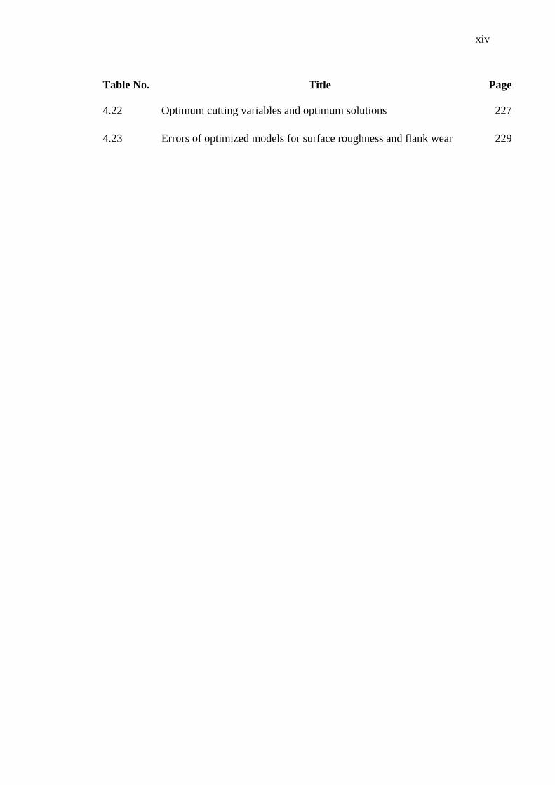
Table No. Title Page
4.22 Optimum cutting variables and optimum solutions 227
4.23 Errors of optimized models for surface roughness and flank wear 229
xv
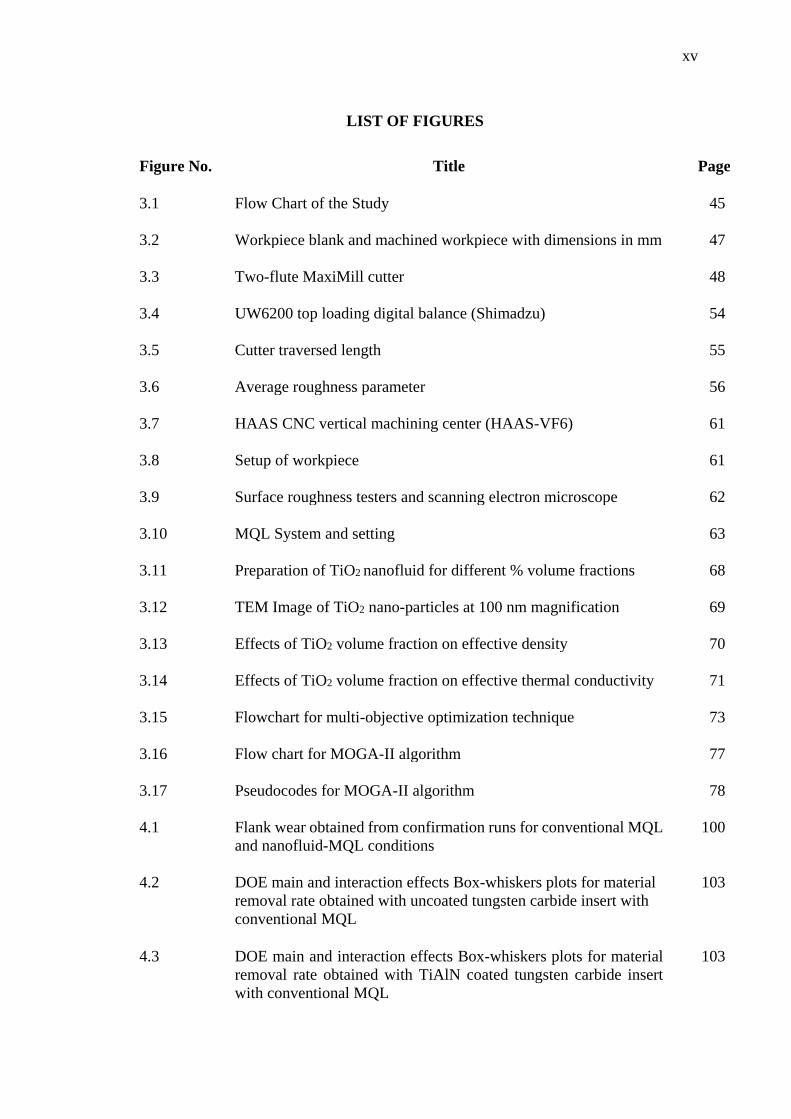
LIST OF FIGURES
Figure No. Title Page
3.1 Flow Chart of the Study 45
3.2 Workpiece blank and machined workpiece with dimensions in mm 47
3.3 Two-flute MaxiMill cutter 48
3.4 UW6200 top loading digital balance (Shimadzu) 54
3.5 Cutter traversed length 55
3.6 Average roughness parameter 56
3.7 HAAS CNC vertical machining center (HAAS-VF6) 61
3.8 Setup of workpiece 61
3.9 Surface roughness testers and scanning electron microscope 62
3.10 MQL System and setting 63
3.11 Preparation of TiO2 nanofluid for different % volume fractions 68
3.12 TEM Image of TiO2 nano-particles at 100 nm magnification 69
3.13 Effects of TiO2 volume fraction on effective density 70
3.14 Effects of TiO2 volume fraction on effective thermal conductivity 71
3.15 Flowchart for multi-objective optimization technique 73
3.16 Flow chart for MOGA-II algorithm 77
3.17 Pseudocodes for MOGA-II algorithm 78
4.1 Flank wear obtained from confirmation runs for conventional MQL
and nanofluid-MQL conditions
100
4.2 DOE main and interaction effects Box-whiskers plots for material
removal rate obtained with uncoated tungsten carbide insert with
conventional MQL
103
4.3 DOE main and interaction effects Box-whiskers plots for material
removal rate obtained with TiAlN coated tungsten carbide insert
with conventional MQL
103

xvi
Figure No. Title Page
4.4 DOE main and interaction effects Box-whiskers plots for material
removal rate obtained with TiAlN+TiN coated tungsten carbide
insert with conventional MQL
104
4.5 DOE main and interaction effects Box-whiskers plots for material
removal rate for uncoated tungsten carbide insert with nanofluid
MQL
104
4.6 Significance of input parameters for material removal rate for
different cutting tools with different cooling conditions
105
4.7 Variations of material removal rate against depth of cut and feed
rate
106
4.8 DOE main and interaction effects Box-whiskers plots for surface
roughness for uncoated tungsten carbide insert with conventional
MQL
108
4.9 DOE main and interaction effects Box-whiskers plots for surface
roughness for TiAlN coated tungsten carbide insert with
conventional MQL
108
4.10 DOE main and interaction effects Box-whiskers plots for surface
roughness for TiAlN+TiN coated tungsten carbide insert with
conventional MQL
109
4.11 DOE main and interaction effects Box-whiskers plots for surface
roughness for uncoated tungsten carbide insert with nanofluid-
MQL
109
4.12 Significance of input parameters for surface roughness
for various cutting tools with different cooling conditions
111
4.13 Variations of surface roughness against input cutting parameters
with uncoated tungsten carbide insert in conventional MQL
113
4.14 Variations of surface roughness against input cutting parameters
with uncoated tungsten carbide insert in nanofluid-MQL
115
4.15 Variations of surface roughness against input cutting parameters
with TiAlN coated carbide insert in conventional MQL
118
4.16 Variations of surface roughness against input cutting parameters
with TiAlN+TiN coated carbide insert in conventional MQL
120

xvii
Figure No. Title Page
4.17 DOE main and interaction effects Box-whiskers plots for flank wear
obtained with uncoated tungsten carbide insert with conventional
MQL
126
4.18 DOE main and interaction effects Box-whiskers plots for flank wear
obtained with TiAlN coated tungsten carbide insert with
conventional MQL
126
4.19 DOE main and interaction effects Box-whiskers plots for flank wear
obtained with TiAlN+TiN coated tungsten carbide insert with
conventional MQL
127
4.20 DOE main and interaction effects Box-whiskers plots for flank wear
obtained with uncoated tungsten carbide insert with nanofluid MQL
127
4.21 Significance of input parameters for flank wear for various
cutting tools with different cooling conditions
129
4.22 Variations of flank wear against input cutting parameters with
uncoated tungsten carbide insert in conventional MQL
130
4.23 Variations of flank wear against input cutting parameters with
TiAlN coated insert in conventional MQL
132
4.24 Variations of flank wear against input cutting parameters with
TiAlN+TiN coated insert in conventional MQL
133
4.25 Variations of flank wear against input cutting parameters with
uncoated tungsten carbide insert in nanofluid-MQL
135
4.26 Wear maps for uncoated tungsten carbide insert in flooded and
conventional MQL
145
4.27 Wear maps for uncoated tungsten carbide insert in nanofluid-MQL
machining
146
4.28 Wear maps for TiAlN coated inserts in flooded and conventional
MQL
148
4.29 Wear maps for TiAlN+TiN coated inserts in flooded and 150
conventional MQL
4.30 Performance comparison of three inserts in conventional MQL
machining
152

xviii
Figure No. Title Page
4.31 SEM micrographs of uncoated tungsten carbide in conventional
MQL conditions at speed=5300 RPM, feed rate = 440 mm/min,
MQL flow rate = 0.83 ml/min
155
4.32 SEM micrographs of uncoated tungsten carbide in conventional
MQL conditions speed=5400 RPM, feed rate = 379 mm/min, MQL
flow rate = 0.65 ml/min.
157
4.33 SEM micrographs of uncoated tungsten carbide insert for
conventional MQL at depth of cut = 2.0 mm
159
4.34 SEM micrographs of uncoated tungsten carbide insert for
conventional MQL at speed=5500 rpm and depth of cut =3.0 mm
160
4.35 SEM micrographs of uncoated tungsten carbide insert for
conventional MQL after machining at depth of cut = 3.0 mm,
speed = 5300 rpm, feed rate = 318 mm/min
160
4.36 Comparison of tool damage in flooded and MQL machining
conditions for uncoated tungsten carbide insert for conventional
MQL
162
4.37 SEM micrographs of TiAlN coated carbide insert for conventional
MQL at speed=5300 rpm, feed rate = 440 mm/min, MQL flow
rate = 0.83 ml/min
164
4.38 SEM micrographs TiAlN coated carbide insert for conventional
MQL speed=5400 rpm, feed rate = 379 mm/min, MQL flow
rate = 0.65 ml/min
166
4.39 SEM micrographs of TiAlN coated carbide insert for conventional
MQL depth of cut = 2.0 mm
167
4.40 SEM images of TiAlN coated carbide insert for conventional MQL
at speed = 5500 rpm
169
4.41 SEM micrographs of TiAlN coated carbide insert after machining
at depth of cut = 3.0 mm, speed = 5300 RPM, feed
rate = 318 mm/min
169
4.42 Comparison of tool damage in flooded and MQL machining
conditions for Tool coated with TiAlN
171
4.43 SEM micrographs of TiAlN+TiN coated carbide insert for
conventional MQL at speed=5300 rpm, feed rate = 440 mm/min,
MQL flow rate = 0.83 ml/min
173

xix
Figure No. Title Page
4.44 SEM micrographs of TiAlN+TiN coated carbide insert for
conventional MQL at speed=5400 rpm, feed rate = 379 mm/min,
MQL flow rate = 0.65 ml/min
174
4.45 SEM micrographs of TiAlN+TiN coated carbide insert for
conventional MQL with depth of cut = 2.0 mm
177
4.46 SEM micrographs of TiAlN+TiN coated carbide insert for
conventional MQL at speed=5500 rpm
179
4.47 SEM micrographs of TiAlN+TiN coated carbide insert for
conventional MQL after machining at depth of cut = 3.0 mm,
speed = 5300 rpm, feed rate = 318 mm/min
180
4.48 Comparison of catastrophic tool damage in flooded and MQL
machining conditions for TiAlN+TiN coated insert in conventional
MQL
181
4.49 EDX spectrums for unused tools 184
4.51 EDX spectrums of tools for Set -1 in conventional MQL conditions 185
4.52 EDX spectrums of tools for set -2 in conventional MQL conditions 186
4.53 SEM micrographs and EDX patterns for the machining condition
with speed = 5400 rpm, feed rate = 370 mm/min, depth of
cut = 2.25 mm, MQL flow rate = 0.65 ml/min, nanofluid-volume
fraction = 0.5%
188
4.54 SEM micrographs and EDX patterns for the machining condition
with speed = 5300 rpm, feed rate = 300 mm/min, depth of
cut = 3.0 mm, MQL flow rate = 0.48 ml/min, nanofluid-volume
fraction = 1.5%
189
4.55 SEM micrographs and EDX patterns for the machining condition
with speed = 5300 rpm, feed rate = 440 mm/min, depth of
cut = 3.0 mm, MQL flow rate = 0.83 ml/min, nanofluid-volume
fraction = 1.5%.
191
4.57 SEM and EDX patterns for the machining conditions with
speed = 5500 rpm, feed rate = 440 mm/min, depth of cut = 1.5 mm,
MQL flow rate = 0.83 ml/min, nanofluid-volume fraction = 1.5%
195
4.58 SEM micrographs and EDX patterns for the machining condition
with speed = 5500 rpm, feed rate = 440 mm/min, depth
of cut = 1.5 mm, MQL flow rate = 0.48 ml/min, nanofluid-volume
fraction = 3.5%
197

xx
Figure No. Title Page
4.59 SEM micrographs and EDX patterns for the machining condition
with speed = 5500 rpm, feed rate = 300 mm/min, depth of
cut = 3.0 mm, MQL flow rate = 0.48 ml/min, nanofluid-volume
fraction = 3.5%
199
4.60 SEM micrographs and EDS patterns for the machining condition
with speed = 5500 RPM, feed rate = 440 mm/min, depth of
cut = 3.0 mm, MQL flow rate = 0.48 ml/min, nanofluid-volume
fraction = 1.5%
200
4.61 SEM micrographs and EDX patterns for the machining condition
with speed = 5200 rpm, feed rate = 370 mm/min, depth
of cut = 2.25 mm, MQL flow rate = 0.65 ml/min, nanofluid-volume
fraction = 2.5%
201
4.62 SEM micrographs and EDX patterns for the machining condition
with speed = 5600 rpm, feed rate = 370 mm/min, depth of
cut = 2.25 mm, MQL flow rate = 0.65 ml/min, nanofluid-volume
fraction = 2.5%
203
4.63 SEM micrographs and EDX patterns for the machining condition
with speed = 5400 rpm, feed rate = 510 mm/min, depth of
cut = 2.25 mm, MQL flow rate = 0.65 ml/min, nanofluid-volume
fraction = 2.5%
205
4.64 SEM micrographs and EDX patterns for the machining condition
with speed = 5400 rpm, feed rate = 370 mm/min, depth of
cut = 2.25 mm, MQL flow rate = 0.65 ml/min, nanofluid-volume
fraction = 4.5%
207
4.65 SEM micrographs and EDX patterns for the machining condition
with speed = 5400 rpm, feed rate = 370 mm/min, depth of
cut = 2.25 mm, MQL flow rate = 1.0 ml/min, nanofluid-volume
fraction = 2.5%
208
4.67 SEM micrographs and EDX patterns for the machining condition
with feed rate = 370 mm/min, depth of cut = 3.75 mm, MQL flow
rate = 0.65 ml/min, nanofluid volume fraction = 2.5%
212
4.68 Deepest dimension extending into the tool body for determining
volumetric flank wear of uncoated tungsten carbide insert in
conventional MQL and nanofluid-MQL machining
219
4.69 Deepest dimension extending into the tool body for
determining volumetric flank wear of TiAlN and TiAlN+TiN
coated inserts in conventional MQL machining
220

xxi
Figure No. Title Page
4.70 Bubble chart showing Pareto designs distribution with input
parameters for uncoated tungsten carbide insert in conventional
MQL machining
222
4.71 Bubble chart showing Pareto designs distribution with input
paramters for TiAlN coated carbide insert in conventional MQL
machining
223
4.72 Bubble chart showing Pareto designs distribution with depth of cut
for TiAlN+TiN coated carbide insert in conventional MQL
machining
225
4.73 Bubble chart showing Pareto designs distribution with input
parameters for uncoated tungsten carbide insert in nanofluid-MQL
machining
226
4.74 Flank wear obtained from confirmation runs for conventional
MQL and nanofluid-MQL conditions
230

xxii
LIST OF SYMBOLS
Symbol Description
A0, β0, C0 Constant
Ai, Aii, Aij Regression coefficient
AISI 1040 A type of steel alloy
Al2O3 Aluminium oxide
Bi, Bii, Bij Regression coefficient
βi, βij, βii Regression coefficient
BCBN Binder-less Cubic Boron Nitride
Ci, Cii, Cij Regression coefficient
CBN Cubic Boron Nitride
Co Cobalt
C45 A type of steel alloy
CuO Copper oxide
CNT Carbon nanotube
ε Experimental error
f Function
F-ratio Fisher distribution
HAAS HAAS Automation, Inc.
K20 Tool grade
k Thermal conductivity
MSR-10D Type of Tribotest
Lc Tool extent

xxiii
Symbol Description
mm Millimeter
min Minute
MOGA-II Multi-Objective Genetic Algorithm (II)
NiTi Nickel-Titanium alloy
NAK80 40 HRC pre-Hardened, high performance, high precision, mold steel
PCD Polycrystalline Diamond
PCBN Polycrystalline Boron Nitride
Density
Ra Average roughness parameter
R2 Coefficient of Determination
SiO2 Silicon dioxide
t Time
T6 A type of heat treatment
TiAlN Titanium Aluminium Nitride
TiN Titanium Nitride
Ti6A14V A type of Titanium-Aluminium-Vanadium alloy
TiO2 Titanium dioxide
TNT Titanate tubes
UNS S34700 Grade 347 austenitic stainless steel
VDI-3198 Hardness test method
WC Tungsten carbide
wt % Weight %
ZnO Zinc oxide

xxiv
Symbol Description
xmax Maximum value of the variable
xmin Minimum value of the variable
y Response
42CrMo4 A type of soft steel

xxv
LIST OF ABBREVIATIONS
AA Aluminum alloy
ANOVA Analysis of Variances
ASME American Society for Mechanical Engineers
BUE Built Up Edge
CCD Central composite design
CNC Computer Numerical Control
DLC Diamond-like-carbon
DOE Design of experiment
FESEM Field Emission Scanning Electron Microscope
FW Flank Wear
G-ratio Grinding ratio
HPJAM High Pressure Jet-Assisted Machining
HPC High Pressure Coolants
ISO International Standards Organization
MCDM Multi-Criteria Decision Making
MQL Minimum quantity lubrication
MWF Metal working fluids
MVO Minimum volume of oil
MRR Material Removal Rate
M-ratio Machining Ratio
NACFAM National Council for Advanced Manufacturing
NIOSH National Institute for Occupational Safety and Health
PVD Physical vapor deposition

xxvi
rpm Revolutions per minute
RSM Response surface methodology
SAE Society of Automotive Engineers
SEM Scanning Electron Microscope
SR Surface Roughness
TEM Transmission Electron Microscope
UHPC Ultra-High Pressure Cooling

CHAPTER 1
INTRODUCTION
1.1 INTRODUCTION
Minimum quantity lubrication (MQL) refers to the application of a miniscule
quantity of coolant, typically of a flow rate of 10 to 100 ml/hour (Kamata and Obikawa,
2007). Reducing the environmental impacts of machining are required in order to attain
the sustainable and cleaner production. As developing alternative manufacturing process
technologies for machining is still a prohibitive task, preventing the negative
environmental impact of machining can be achieved essentially by operating modification
of existing processes (Hanafi et al., 2012). As the manufacturing world is in a continuous
pursuit of investigating the methods in order to increase the process performance and to
reduce the production costs, in addition to the growing environmental concerns (Fratila,
2013), minimum quantity lubrication process can offer the near-term solution to the
problem. Driven by pressure from international environmental protection agencies,
energy consumption and natural resources conservation laws enforced by public
authorities, manufacturing industry and the concerned research centers are forced to focus
their efforts on researching alternative production processes, creating technologies to
minimize the use and production of environmentally hostile residues. MQL has
demonstrated as a successful near-dry machining technique as well as a globally-
acknowledged option compared to complete dry and wet cutting conditions from the
perspective of cost, ecological, human health issues and machining process performance
(Lawal et al., 2013). MQL is a sustainable manufacturing approach which is vital in the
current scenario of manufacturing industry as it incorporates all the issues related to
sustainability. The cost of cutting fluids range from 7 to 17% of the total machining cost
while another estimate gives this cost as 15-20 % of total machining cost compared to the

2
tool cost which ranges from 2 to 4% (Attanasio et al., 2006; Lawal et al., 2013; Li et al.,
2014). Therefore, the minimization of metal working fluids can serve as a direct gauge of
sustainable manufacturing.
Machining with MQL has been extensively applied in many machining processes
such as drilling (Filipovic and Stephenson, 2006; Davim et al., 2007), milling (Lacalle et
al., 2006; Liao and Lin, 2007), turning (Davim, 2007; Kamata and Obikawa, 2007) and
MQL grinding (Silva et al., 2005; Shen et al., 2008). Since no huge power consuming
auxiliary equipment such as compressors, chillers and pumps are required as compared
to flooded machining, hence a marked reduction in energy consumption in MQL
machining. The use of empirical approach together with the implementation of
experimental design techniques as well as application of statistical data analysis
techniques are gaining recognition on account of the simplicity involved in the model
making procedure and the accuracy of the prediction obtained for the specific cutting
conditions domain (Kannan and Baskar, 2013).
Aluminium alloys are the most machinable amongst the metals with a wide range
of applications due to mechanical and corrosion resistance with lower cutting forces as
well as low cutting temperatures (Kelly and Cotterell, 2002; Ariff et al., 2012). However,
due to highly adhesive characteristics of aluminium and its alloys more effective
lubrication is required for these alloys although these are not hard and difficult-to-cut
especially with alloys containing hard inclusions such as aluminium oxide, silicon
carbide, or free silicon (Kelly and Cotterell, 2002; Wakabayashi et al., 2007). On the other
hand, machining of aluminium alloys results in the generation of very fine metallic
particles in the form of ultrafine dust particles with longer air-borne suspension time
hence harmful for the health of the operator (Songmene et al., 2011).
Significance of machining processes optimization arises from the prerequisite for
an economic and feasible performance of the machining processes. Practical
manufacturing processes are illustrated by conflicting and often incompatible measures
of performance such as quality and productivity (Kumar and Chhabra, 2014). The multi-
objective optimization techniques are used to find out the trade-offs among the conflicting
performance measures in a machining process in order to achieve performance