performance evaluation for plas a sp ay aski g tape
TRANSCRIPT

L
1 INCH-POUNDI
MIL-STD-181915 September 1992
MILITARY STANDARD
PERFORMANCE EVALUATION FORPLASMA SPRAY MASKING TAPE
AMSC No. N/A AREA: MFFP
‘L-. . .
~ Appruved fa put)]ic ~ie~: &srn~ti~ is u~imi~.
Downloaded from http://www.everyspec.com
... , .. .. .
MIL-STD-1819-
DEPARTMENT OF DEFENSEWASHINGTON DC 20301 -8(XY3
PERFORMANCE EVALUATION FOR PLASMA SPRAY MASKING TAPE
1. This military standard is approved for use by all Departments and Agencies of theDepartment of Defense.
2. Beneficial comments (recommendations, additions, deietions) and any pertinent datawhich may be of use in improving this document, should be addressed to: ASC/ENES,Wright-Patterson AFB OH 45433-6503 by using the self-addressed Standardization DocumentImprovement Proposal (DD Form 1426) appearing at the end of this document, or by letter.
w
Downloaded from http://www.everyspec.com

—.
. . .
MIL-STD-1819
-.
FOREWORD
The variety of grit blasting and thermal spray processes prevents one tape from being the idealtape for all applications. ThIS standard has been developed to establish the requirements andperformance evaluation process for plasma spray masking tapes used for thermal sprayapplications.
L-
. . .111
Downloaded from http://www.everyspec.com
PAGE
MxbsTD-1819
CONTENTS
PAGE
I
1.1.11.2
2.2.12.1.12.22.3
3.
4.4.14.1.14.1.24.1.34.1.44.1.54.1.64.1.74.1.84.1.94.1.104.1,11
5.5.15.25.35.45.55.6
6.6.16.26.3
SCOPE . . . . . . . . . . . . . . . . . . . . . . . . . . . . . . . . . . . . . . . . . . . . . . . . . . .1scope . . . . . . . . . . . . . . . . . . . . . . . . . . . . . . . . . . . . . . . . . . . . . . . . ...-...1Classification . . . . . . . . . . . . . . . . . . . . . . . . . . . . . . . . . . . . . . . . . . . . ...--..1
APPLICABLE DOCUMENTS . . . . . . . . . . . . . . . . . . . . . . . . . . . . . .--.....1Governrnentdocuments . . . . . . . . . . . . . . . . . . . . . . . . . . . . . . . . . . . . . . . ...-1Specifications, standards, andhandbooks . . . . . . . . . . . . . . . . . . . . . . . . . . ...1Non430vemment publications . . . . . . . . . . . . . . . . . . . . . . . . . . . . . . . . . . ...2Order of Precedence . . . . . . . . . . . . . . . . . . . . . . . . . . . . . . . . . . . . - . . . . . . ...2
DEFINITIONS . . . . . . . . . . . . . . . . . . . . . . . . . . . . . . . . . . . . . . . . . . . . . . . ...2
GENERAL REQUIREMENTS . . . . . . . . . . . . . . . . . . . . . . . . . . . . . . . . . . ...3Tape . . . . . . . . . . . . . . . . . . . . . . . . . . . . . . . . . . . . . . . . . . . . . . . . . . . . . . ...3Materials . . . . . . . . . . . . . . . . . . . . . . . . . . . . . . . . . . . . . . . . . . . . . . .-3Adhesive . . . . . . . . . . . . . . . . . . . . . . . . . . . . . . . . . . . . . . . . . . . . . . . . . . . . ..SRolls . . . . . . . . . . . . . . . . . . . . . . . . . . . . . . . . . . . . . . . . . . . . . . . . . ..,..3Width . . . . . . . . . . . . . . . . . . . . . . . . . . . . . . . . . . . . . . . . . . . . . . . . . . . . . ...3 _Thickness . . . . . . . . . . . . . . . . . . . . . . . . . . . . . . . . . . . . . . ...3Peel adhesion . . . . . . . . . . . . . . . . . . . . . . . . . . . . . . . . . . . . . . . . ...--.3Tensilestrength . . . . . . . . . . . . . . . . . . . . . . . . . . . - . . . . . . . . . . . ...-.3Marking ofrolls . . . . . . . . . . . . . . . . . . . . . . . . . . . . . . . . . . . . . . . . . . . ...-.3Packaging . . . . . . . . . . . . . . . . . . . . . . . . . . . . . . . . . . . . . . . . . . . . . . . . . . ...3Shelf like . . . . . . . . . . . . . . . . . . . . . . . . . . . . . . . . . . . . . . . . . . . . -....3Storage requirements . . . . . . . . . . . . . . . . . . . . . . . . . . . . . . . . . . . . . . . ...3
DETAILED REQUIREMENTS . . . . . . . . . . . . . . . . . . . . . . . . . . . .- ...-.4Tape application . . . . . . . . . . . . . . . . . . . . . . . . . . . . . . . . . . . . . . . .-......4Test substrate . . . . . . . . . . . . . . . . . . . . . . . . . . . . . . . . . . . . . . . . . . . . . . . ...-4Gntblaating . . . . . . . . . . . . . . . . . . . . . . . . . . . . . . . . . . . . . . . . . . . . --5Plasma spray operations . . . . . . . . . . . . . . . . . . . . . . . . . . . . . . . . . . . . . . ...-5Tape removal operations . . . . . . . . . . . . . . . . . . . . . . . . . . . . . . . . . . ...6Tape disposal . . . . . . . . . . . . . . . . . . . . . . . . . . . . . . . . . . . . . . . . . . ...-....6
NOTES . . . . . . . . . . . . . . . . . . . . . . . . . . . . . . . . . . . . . . . . . . . . . . . . . .-...7Intended use . . . . . . . . . . . . . . . . . . . . . . . . . . . . . . . . . . . . . . . - . . ...-....7Acquisition requtiments ..,.. . . . . . . . . . . . . . . . . . . . . . . . . . . . ..-.-..-7Keywords . . . . . . . . . . . . . . . . . . . . . . . . . . . . . . . . . . . . . . . . . . . . . -. -....7
iv
Downloaded from http://www.everyspec.com

—.
. . . . . . . ,,.
MIL-STD-1819
..-
Commm
FIGURRS
1.2.3.
Testsubstrate . . . . . . . . . . . . . . . . . . . . . . . . . . . . . . . . . . . . . . . . . . . . . . . . ...4Sample tapeapplication . . . . . . . . . . . . . . . . . . . . . . . . . . . . . . . . . . . . . . . . ...5Plasma arc spraygun . . . . . . . . . . . . . . . . . . . . . . . . . . . . . . . . . . . . . . . . . . ...6
L.
-.
v
Downloaded from http://www.everyspec.com

---
MIL-STD-1M9
1. SCOPE
1.1 Scope This standaxd establishes the mqdrements for evaluating tkrmal spray maskingtapes subject to grit blasting and plasma spraying o p e ti o m .
1.2 Classification
1.2.1 The thermal spray masking tapes covered by this standard include the composite tapes
-----
listed below:
12.1.1 Layup No. 1.
1.2.1.2 Layup No. 2.
L2.1.3 Layup No. 3.
1.2.1.4 Layup No. 4.
1.2.1.5 Layup No. 5
Silicone adhesiveGlass cloth backingSilicone acihtxive
Metallic foilGlass cloth backingSilicone adhesive
Silicone rubber topcoatGlass cloth bacldngSilicone adhesive
Glass cloth backingSilicone adhesive
Synthetic rubber topcoatGlass cloth backingSynthetic rubber adhesive
1.2.2 Other tape configurations may be evaluated under this standard, if specified by theacquisition achvity (see 6.2.3).
2. APPLICABLE DOCUMENTS
2.1 Government documents
2.1.1 Specifications, standards, and handbooks. The foliowing specifications, standards, andhandbooks form a part of this document to the extent specified herein. Unless otherwisespecified, the issues of - documents are those listed in the issue of the Department ofDefense Index Specifications and Standards (DoDISS) and supplement thereto, cited in thesolicitation (see 6.2).
SPECIFICATIONS
Federal
PPP-T-680 Tape, Pressure-Sensitive Adhesive: Packaging and Packing of
(Unless otherwise indicated, copies of federal and military specifications, standards, and\ hmdbmks am available from the Naval %b!ieanows and Forms Center, Smdmdization
DocumenLs Order Desk, Bldg 4D, 700 Robbins Avenue, Philadelphia PA 1911 1-5094.)
1
Downloaded from http://www.everyspec.com

MIL-STD-1819-
2.2 Non-Government publications The following documents form a part of this document tothe extent spedied herein. Unless othawiae spedied, the issues of the d=umcnk which areDoD adopted me those listed in the issue of the DoDISS cited in the solicitation. Unlessotherwise specified, the issues of documents not listed in the DoDISS are the issues of thedocuments cited ]n the solicitation (see 6.2).
AMERICAN SOCIETY FOR TESTLNG AND MATERIALS (ASTM)
ASTM D3330 Standard Test Methods for Peel Adhesion of Pressure-Sensitive Tapeat 180 Degree Angle
ASTM D3652 Standard Test Method for Thiclmess of Pressure-Sensitive andGummed Tapes (DoD adopted)
ASTM D3715 Standard Prachce for Quality Assurance of Pressure-SensitiveTapes (DoD adopted)
ASTM D3759 Standard Test Method for Tensile Strength and Elongation ofPressure-Sensitive Tapes (DoD adopted)
ASTM D3811 Standard Test Method for Unwind Force of Pressure-Sensitive Tapes
(Application for copies should be addressed to the American Society for Testing and Materials,1916 Race Street, Philadelphia PA 19103 -1187.)
(Non-Government standards and other publications are normally available horn theorganizations that prepare or distribute the documents. These documents also may be availablein or through libraries or other information services.)
2.3 Order of Precedence, In the event of a conflict between the text of this document and thereferences cited herein (except for related associated detail specifications, specification sheets, orMS standards), the text of this document takes precedence. Nothing in this document, however,supersedes applicable laws and regula~ons unless a specific exemption has been obtained.
3.0 DEFINITIONS
3.1 Grit blasting. Forceful direction of abrasive particles against the surface of a workpiece, toremove the surface layer and produce an absohJtel y clean surface.
3.2 Overspray. The excess spray material that is not deposited on the part being sprayed.
3.3 Plasma. An electrically neutral, tngh temperature lomzed gas composed of Ions, electrons,and neutral particles.
3.4 Plasma spraying, Producing a coating by passing a material in powder form through aplasma flame and depositing the subsequently heat-softened particles onto a base material orsubstrate.
3.5 Substrate. The material, workpiece, or substance on which the coating is deposited.
2
Downloaded from http://www.everyspec.com
MIL-STD-1819---
3.6 l%- spray. Any coating process in which partids are heated to a molten or plasticstate and propelled onto a substrate to form a coating. Thermal spy includes combustion spray,
I plasma spay, and electric arc spray. Feed stock may be wire, powder, or rod.
1 4.0 GENERAL REQUIREMEN’IY31
4.1 Thpe The tape furnished shall be a product which meets the requirements specifiedin 4.1.1 through 4.11, and the Quality Assurance requirements of ASTM D37 15. ‘Ihe tapshall be tested and meet the rwp.irements specified in section 5.
4.1.1 Materials. The materials used in the manufacturing of the tape shall emsum perfOnn-of the tape,rn accmda.nce with the requirements of this standard.
4.1.2 Adhesive The tape adhesive shall be able to withstand the rigors of both grit blastingand plasma spraying.
4.1.3 Rolis. The tape shall be evenly and uniformly wound, adheswe side on cores made ofpaper or plastic. The core shall have a rigidity which prevents distortion of the roll under normalconditions of transportation, storage, or use. A release liner should be used with tapes requiringexcessive unwind force, or if specified by the acquisition activity (see 6.2.4).
4.1.4 Width. The width of the tape shall be 0.25,0.50, 0.75, 1.00, 1.50, 2.00, or 3.00 inches, o~‘+ other commercially available widths, as specified by the acquisition activity (see 6.2.5). A
tolerance of ~ 0.03 inches shall be acceptable.
4.L5 Thickness. The tape thickness shall be measured in accordance with ASTM D3652.
4.1.6 Peel adhesion. The tape’s adhesion shall be measured in accordance with ASTM D3330.
4.1.7 ‘lbsile strength.ASTM D3759.
4.1.8 Marking of rolls.of the core:
The tape’s tensile slrength shall be measured in accordance with
The rolls shall be marked with the following information on the inside
4.1.8.1
4.1.8.2
4.1.8.3
4.1.8.4
4.1.8.5
Manufacturer’s name
Manufacture’s stock number.
Tape width and length.
Date of manufacture.
Date of expiration.
4.1.9 Packaging. The tape, upon manufacture, shall be packaged in plastic as specified inPPP-T-680.
L- 4.1.10 Shelf life. Shelf life shall be a minimum of 12 months. Shelf life is defined as being thespan of time from the date of manufacture to the date of expiration.
3
Downloaded from http://www.everyspec.com
MIIATD-1819
I -
4.1.11 Storage requiremen& ~~sk~kswdti titi~p~k~g, tiac~ilocation. The tspe shsll not be stmed clase to bt sources, such ss steam pipes, radis~ sndfurnaces. Storage conditions of approximately seventy degrees Fahrenheit and forty to fiftypercent relative humidity are considered optimum.
5.0 DETAILED REQUIREMENTS
5.1 ‘Ihpe application. Two layem of the tape shall be applied to the test substrate.
5.L1 Unwind force. If a tape does not include a release liner, the tape shall peel off the rollreadily, requiring an unwind force of less than 3 Ibfm. Unwind force shall be detmmined inaccmhmce with ASTM D38 11.
5.1.2 Release liner. If a release liner is included in the tape packaging, it shall readily separatehorn the tape during appbcation.
5.1.3 Adherence. The tape shall readily adhere to the test specimen and conform to curves andsharp comers.
5.1.4 Rejection criteria. Failure to meet any of the above criteria shall be cause for rejection.
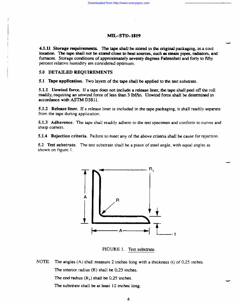
5.2 Test substrate. The test substrate shall be a piece of steel angle, with equal angles asshown on figure 1.
RI
R
‘./ ; +
+ ’—--+
FIGURE 1. Test substrate.
T- t
NOTE: The angles (A) shall measure 2 inches long with a thickness (t) of 0.25 inches.
The interior radius (R) shall be 0.25 inches.
The end radms (Rl) shall be 0.25 inches.
The substrate shall be at least 12 inches long.
4
-
Downloaded from http://www.everyspec.com

MIL-STD-1819
-.52.1 Within one hour after completing decreasing operations, the sample tape shaII be appliedonto the substrate as shown on figure 2. Tape shall be burnished (rubbed down) with a squeegee,spatula, or other device to insure maximum adhesion of the adhesive.
APPLY 2 PIECES OF TAPEON FIAT PORTIONOF SU8STRATE
,. .;..,. ..::..,:,.t,.,:.,. ::. .;... . ..::.....:,.. ,
WRAP 3 PIECES OF TAPETO THE TEST SUBSTRATE II
APPLY 2 PIECES OF TAPEOVER ANGLE EDGES
FIGURE 2. Sample tape application.
L-
5.2.2 Within one hour after applying the tape to the substrate, the taped substrate shall besubjected to grit blasting and to plasma spraying operations as specified in sections 5.3 and 5.4.
53 Grit blasting. The tape applied to the test substrate shall be subjected to the followingparameters.
53.1 Virgin 20 to 30 aluminum oxide grit shall be used.
5,.3.2 Nozzle pressure of 80 pounds per square inch shall be used.
5.3.3 Nozzle to part stand off distance shall be 5 inches.
5.3.4 All exposed areas of the substrate shall be blasted to clean white metal.
53.5 Failure to completely protect the covered area born grit blasting shall be cause forrejection. Failure shall include tearing of the tape, loss of tape adhesion, grit blast mediapenetration, abrasion of edges, and separation of laminations.
5.4 Plasma spray operations
L 5.4.1 M&r - t&e prewioua Asps, the tape shall be au&md to the folkmng plasmaspraying conditions (see figure 3).
J
Downloaded from http://www.everyspec.com

MIL-STD-1819
I
\ WATER COOLING
‘Ill
?POWOER
~ “ i
PIASMA \.,. ... 141
TUNGSTEN‘“III
(PtASMA ‘
f
~~”” ~ ~~
J4COATING -
)
sUBSTRATE 1
FIGURE 3. Plasma arc spray gun.
5.4.1.1 Composite nickel aluminum powder conforming to GEB50TF56, PWA 1337,METCO 450, or equivalent (see 6.4), shall tE used.
5.4.1.2 The nozzle to part standoff distance shall be 5 inches.
5.4.1.3 The taped substrate shall be exposed for 30 seeonds or for a deposihon ttuckness of0.050 inches, whichever is the longest. Edges, inside and outside diameters, and flat sechons ofth e test substrate shall be exposed.
5.4.2 Failure to complete] y protect the part from plasma spraying shall be cause for rejectionF~lure shall include exposure of the test speeimen due to tape tearing, burning, lifting,shrinkage, edge loss, or separation of laminates.
5.5 Tape removal operations
5.5.1 The tape exposed to the above gritblasting and piasma spray operations shall readily beremoved from the test specimen without tearing, with no adhesive residue remaining.
5.5.2 Edges shall be sharp, unifomn, with no overspray.
5.5.3 Faihrre to meet the above criteria shall be cause for rejection.
w
5.6 Tape disposal. The UWI ta p e shall not create a hazardous waste disposal problem. If thetape is deemed iner4 yet the plasma spray coating overspray is deemed hazardous, the agencycontaminating the tape shall dispose of the tape in accordance with federal, state, and bea! -environmental regulations.
6
Downloaded from http://www.everyspec.com

MIL-STD-1819L
6. NOTES
(This section contains information of a general or explanatmy nature that maybe helpful, but isnot mandatory.)
6.1 Intended use. ‘l%eperformance evaluation requirements for plasma spray masking tapecovered by this standard is intended for use by tape manufacturers, and government or industrythermal spray tape evaluators.
6.2 Acquisition requirements Acquisition documents shall specifj the following:
6.2.1 Title, number, and date of the standmd.
6.2.2 Issue of DoDISS to be cited in the solicitation, and if required, the specific issue ofindividual documents referenced (see 2.1.1 and 2.2).
6.2.3 Whether other tape configurations are to be evaluated (see 1.2.2).
6.2.4 Whether a release liner is required (see 4. 1.3).
6.2.5 Thewidth of the tape (see 4. 1.4).
6.3 Subject term (key word) listing.
+plasma spray
tape evaluation
thermal spray
Custodian:my -MR&r Force- 11Navy - SH
Review activities:Ai.r Force- 71,82
Preparing activity:Mr Force -11
Project No. MFFP-0506
Downloaded from http://www.everyspec.com
)- ,.
I
L-
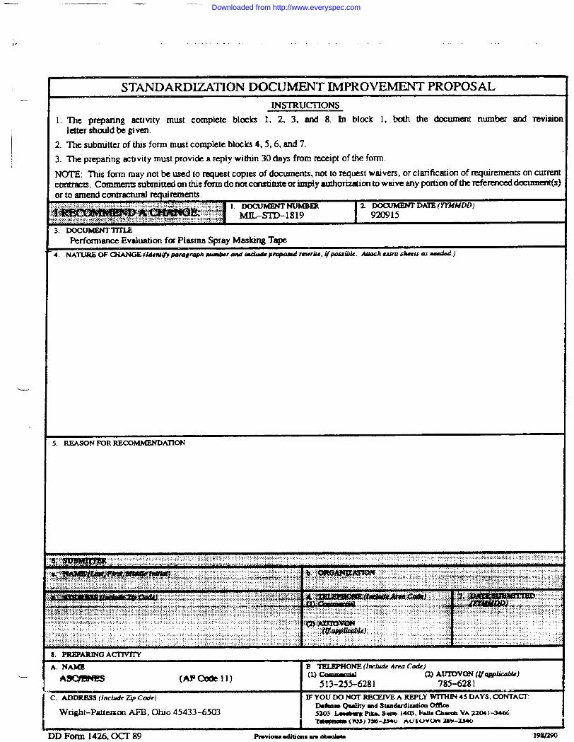
STANDARXXZATION DOCUMENT IMPROVEMENT PROPOSALINSTRUCITONS
1. ~e preparingactivity must complete blocks 1, 2, 3, and 8. In block 1, both the document number and Tovisimletter should be given.
2. ‘he submitter of this form must complete blocks 4,5,6, and 7.3. The preparing activity must provide a reply within 30 days from nxeipt of the form
NOTE: ~s form may not be used to request copies of documents, not to request waivers, or clarification of requirements on curnmcmmxxs. Comments submitted on this form donotcu!stitute orixnp!y authorization to waive any portion of the referenced d~(~jor to amend conuactural requirements.
z DoCUMDW DATE (YYMMDD)
3. DcMxJMENTT1’rUPerformanceEvaluation for Plasma SprayMaskingTape
4. NATURKOF C3iANOE(kient@p amgmph nuatbramd iuhd8 prqmnd mvrk, ~~ibk. A&kachulm skis w nuddd.)
5. REASON FOR RECQMMENDKXION
PREPAIUNG ACtTWIY
,.NAME B TELWHONB (hdude Area Cd)
MJQENE8 (nPOXJell) (1)c Al Q) AUK3VDN (#q@able)
513-255-6281 785-6281>.ADDRESS (Inckte 247 Ccklt) lFYOUDONOTRECEWE A REPLY -IN 45 DAYS, CONTA~
Wnght-Patkmon AFB, Ohio 45433-6503!
IMhm Qualllymd Standudizatkm OflkaS203 Ianbq F’Iko.Sum M03. Faih Chmwb VA 2204 )-3466“1~ (VW) “75B-M4U Au”tuvcnv Z5Y-Z.YUJ
1
IDForm 14= OCT 89 P19viowOdMmsU8Obw 19MZ!XI
Downloaded from http://www.everyspec.com