performance analysis of wlan mac algorithms
TRANSCRIPT

MEE10:91
Performance Analysis of WLAN MACalgorithms
Author:Ramaz Samhan
Amer Khoulani
Supervisor:Dr. Jorgen Nordberg
A Thesis Presented in partial fulfillment of the requirements for the degreeof Master of Science in Electrical Engineering with specialization in
Telecommunication
Blekinge Institution of TechnologyNovember 30, 2010

Abstract
Lately, researchers were trying to put a lot of effort to enhance the perfor-mance of Wireless LANs. IEEE 802.11 algorithm, DCF, was an interestingsubject for studies. Most studies were concentrating on avoiding collisions,packets loss, decreasing transmission delay and enhancing the overall per-formance of the network. Double Increment Double Decrement (DIDD) wasintroduced as a solution that enhance the performance by applying somechanges in the algorithm. The main changes were applied on the ContentionWindow (CW). IEEE 802.11e introduced a new algorithm (EDCA) that in-troduce a QoS to the performance and though improves the overall perfor-mance of the WLAN This thesis aim is to study the performance of threedifferent MAC algorithms by applying two different scenarios on legacy DCF,DIDD and EDCA. Analyzing different output results and checking the QoSof each algorithm. Simulations are implemented in Network Simulator 2(ns-2) to simulate the network and communication procedures. By deducingand analyzing the output results of the main simulation, DIDD shows im-provements that are slightly better than the legacy DCF, while EDCA showsbetter results from both DCF and DIDD. Though, EDCA shows a noticeableenhancement in the performance of the WLAN.

Contents
1 Introduction 41.1 Motivation . . . . . . . . . . . . . . . . . . . . . . . . . . . . . 41.2 Objective . . . . . . . . . . . . . . . . . . . . . . . . . . . . . 51.3 Organization . . . . . . . . . . . . . . . . . . . . . . . . . . . 6
2 Algorithm Description 82.1 Wireless LAN . . . . . . . . . . . . . . . . . . . . . . . . . . . 82.2 IEEE802.11 MAC Layer . . . . . . . . . . . . . . . . . . . . . 92.3 Distributed Coordination Function (DCF) . . . . . . . . . . . 9
2.3.1 CSMA/CA . . . . . . . . . . . . . . . . . . . . . . . . 102.3.2 Binary Exponential Backoff BEB . . . . . . . . . . . . 122.3.3 Disadvantages of DCF . . . . . . . . . . . . . . . . . . 13
2.4 Double Increment Double Decrement DIDD . . . . . . . . . . 132.4.1 DIDD Algorithm . . . . . . . . . . . . . . . . . . . . . 14
2.5 IEEE 802.11e . . . . . . . . . . . . . . . . . . . . . . . . . . . 152.5.1 EDCA . . . . . . . . . . . . . . . . . . . . . . . . . . . 15
3 Simulation 173.1 NS2 Structure . . . . . . . . . . . . . . . . . . . . . . . . . . . 17
3.1.1 The event scheduler . . . . . . . . . . . . . . . . . . . . 183.1.2 NS2 and Split Object Models . . . . . . . . . . . . . . 19
3.2 Simulation Scenario . . . . . . . . . . . . . . . . . . . . . . . . 203.2.1 Simulation Assumptions . . . . . . . . . . . . . . . . . 203.2.2 Scenario . . . . . . . . . . . . . . . . . . . . . . . . . . 20
4 Simulations Results 25
5 Conclusions 29
1

Appendices 32.1 Simulation-Scenario.tcl . . . . . . . . . . . . . . . . . . . . . . 33.2 NS2 modification for NS2 EDCF . . . . . . . . . . . . . . . . 40.3 NS2 modification for DIDD . . . . . . . . . . . . . . . . . . . 40.4 Perl code . . . . . . . . . . . . . . . . . . . . . . . . . . . . . . 40
2

List of Figures
2.1 MAC layer in the IEEE standard [9] . . . . . . . . . . . . . . . 92.2 CSMA/CA algorithm flow chart [8] . . . . . . . . . . . . . . . 112.3 DCF operation [10] . . . . . . . . . . . . . . . . . . . . . . . . 132.4 Difference between DIDD and BEB [6] . . . . . . . . . . . . . 142.5 EDCA in IEEE 802.11e [12] . . . . . . . . . . . . . . . . . . . 162.6 Backoff difference between EDCA and DCF [12] . . . . . . . . 16
3.1 Structure of NS2 [15]. . . . . . . . . . . . . . . . . . . . . . . . 183.2 NS2 C++/OTCL [15] . . . . . . . . . . . . . . . . . . . . . . . 193.3 The Simple Network Topology . . . . . . . . . . . . . . . . . . 213.4 The Complex Network Topology . . . . . . . . . . . . . . . . . 223.5 Trace File format . . . . . . . . . . . . . . . . . . . . . . . . . 24
4.1 The Average Throughput . . . . . . . . . . . . . . . . . . . . . 264.2 The Delivery Ratio . . . . . . . . . . . . . . . . . . . . . . . . 274.3 The Average Delay . . . . . . . . . . . . . . . . . . . . . . . . 274.4 The Average Throughput. . . . . . . . . . . . . . . . . . . . . 284.5 The Delivery Ratio . . . . . . . . . . . . . . . . . . . . . . . . 284.6 The Average Delay . . . . . . . . . . . . . . . . . . . . . . . . 28
3

Chapter 1
Introduction
1.1 Motivation
In the recent years, the use of wireless networks is increasing among the oldwired networks and wireless LANs are becoming a very interesting subjectfor researchers and developers. Also, customers are interested in wirelesstechnologies in their daily life due to its flexibility, ease of use and its perfor-mance.
Among many wireless access technologies, the use of the IEEE 802.11Wireless Local area Networks (WLAN) is becoming very popular due to itsease of installation , the free of charge availability in different circumstancesand its high performance [1].
The IEEE 802.11 technology has been widely used in other areas, suchas wireless sensor networks and wireless mesh networks. Also, the IEEE802.11 network has been considered as an important part in the future 4Gtelecommunication network, where customers may use voice or even videocommunication over the IEEE 802.11 network [1]. The great success of theIEEE 802.11 technology also motivates researchers to devote themselves toimproving the performance of the existing IEEE 802.11 technology. However,it has its own shortcomings: Its performance heavily depends on the selectionof interim hops. An ideal interim hop should have good radio channels withits preceding hop as well as its proceeding hop [2]. However, the availability ofsuch perfect interim hops cannot be always guaranteed in a practical wirelessnetwork [1]. The network resource may not be fully used in the wirelessmulti-hop network because only one pre-determined interim node is involved
4

in the traffic transfer within a particular segment along the entire multi-hoppath [2] . For example, in a two-hop segment, only the node acting as theinterim hop can forward the traffic to the next hop. While other nodes mayalso have good or even better radio channels, they cannot contribute to thetraffic delivery [1].
The IEEE 802.11 medium access control (MAC) is based on the Car-rier Sense Multiple Access with Collision Avoidance (CSMA/CA) princi-ple and The fundamental MAC layer access mechanism of the IEEE 802.11technology is DCF (Distributed Coordination Function); DCF is based onCSMA/CA backoff mechanism for channel access control, where each stationimplements its own backoff procedure for channel access. However, DCF canonly offer a best-effort channel access service, where all stations statisticallyshare the channel fairly but it cannot support QoS (quality of service) dif-ferentiation. The distributed coordination function (DCF) provides a simpleand flexible mechanism for sharing the network medium. DCF defines twomedia access techniques to be employed for frame transmission: The defaultscheme is a two-way handshaking technique called the basic access and anoptional four-way handshaking technique known as Request-To-Send/Clear-To-Send (RTS/CTS) mechanism [2].
DCF main description is to reduce the collision probability among multi-ple stations accessing the same medium. DCF adopts a slotted binary expo-nential backoff mechanism to select the random backoff interval. This ran-dom number is drawn from a uniform distribution over the interval [0, CW-I],where CW is the contention window size and its initial value is CWmin.Inthe case of an unsuccessful transmission, receiving no ACK frame, CW isdoubled. Once CW reaches CWmax, it will remain at this value.After asuccessful transmission, the CW value is reset to CWmin before the randombackoff interval is selected. Each station decrements its backoff counter everyt-SlotTime interval after the wireless medium is sensed to be idle for DlFStime. If the counter has not reached zero and the medium becomes busyagain, the station freezes its counter. When the counter finally reaches zero,the station starts its transmission [3].
1.2 Objective
Despite the the good performance offered by the IEEE 802.11, It can stillfaces some problems that affect its performance. Some of these problems are:
5

BEB scheme suffers from a fairness problem, due to the fact that the schemeresets the contention window of a successful sender to CWmin, while othernodes continue to maintain larger contention windows, thus reducing theirchances of seizing the channel and resulting in channel domination by thesuccessful nodes When the number of stations is low, small CW is desirablesince it reduces the number of empty unused slots [2] For a large number ofstations, larger CW offers better performance since it reduces the probabilityof collisions BEB suppose that the packets were corrupted because of collisiononly and cant differentiate it from the corruption caused by the noise. Thiswill lead to poor performance due to overload in the network [2].
The objective of the thesis work is to study the distributed coordinationfunction DCF performance. The performance will be deduced and analyzedby running a simulation and then compare it to the performance of theimproved DCFs (Learning BEB, DIDD). The study will show what improve-ments were done on this subject. The simulation will be implemented onthe network simulator NS2 and the scripting language used is OTCL (Toolcommand language with object oriented extension) while the mean platformis Linux. The work can be summarized in the following steps:Step-1: Implementing Standard DCF algorithm in NS2Step-2: Implementing Learning BEB and DIDD in NS2Step-3: Comparing the performance of the three algorithmsStep-4: Deducing the results of the improvements in the later two algorithmsStep-5: Suggesting some improvements
1.3 Organization
Our thesis report is structured into the following chapters:
Chapter 2
This chapter is to give first a background about the state of the arts andthen detailed description of DCF algorithm with comprehensive explanationabout its functionality. Also an introduction to DIDD and EDCA. In otherword, it will present a system modeling of DCF.
Chapter 3
6

First, this chapter gives a brief introduction about our simulation plat-form NS2. Also it shows with our assumptions in the available simulationenviroment . Then, it demonstrates the detailed flowchart of our simulationof the standard DCF and the other two algorithms.
Chapter 4
In this chapter, we analysis the results we deduced from our simulationresults. We start by showing the pros and cons of the performance of eachalgorithm. After that, we move to suggest some improvements that can leadto better performance of standard DCF. mentioned cases.
Chapter 5
This chapter summarizes our work during this thesis and initiates somefuture work to be run according to our results.
7

Chapter 2
Algorithm Description
This chapter presents an overview of the Wireless LAN IEEE 802.11 and anintroduction to the distributed coordination function DCF and the BinaryExponential Backoff BEB algorithm used by WLANs to prevent collisions.It also presents two of the modified techniques of DCF, DIDD (Double In-crement Double Decrement)and the Enhanced DCF.
2.1 Wireless LAN
The last two decades has seen an exponential growth in the demand for wire-less services. Wireless Local Area Networks became deployed everywherearound us in the offices, universities, and even our own homes. A wirelesslocal area network uses radio frequency (RF) technology to transmit and re-ceive data over the air medium. The Institute of Electrical and ElectronicsEngineers (IEEE) have established the IEEE 802.11 standard. Due to the lowcost infrastructure along with the ease to use and mobility, the IEEE 802.11is now the most accredited standard for WLANs [1]. The main differencebetween WLANs and LANs is the limited bandwidth and the varying topol-ogy because of the mobility of the nodes [2]. Roughly speaking, a wirelessLAN consists of nodes and access points. A node is usually a computer or aperipheral (such as a printer) with a wireless network adapter (antenna), inWLANs case with an antenna. While the access point will be the transceiver,transmitter and receiver, between the nodes or between the WLAN and an-other network like the Internet [2]. The IEEE 802.11a works in the 5GHZband with a maximum data rate of 54 Mbits per second. a standard uses the
8

same data link layer protocol and frame format as the original standard, butan OFDM based air interface (physical layer). 802.11b has a maximum rawdata rate of 11 Mbits per second. In June 2003, a third modulation standardwas launched: 802.11g. It works in the 2.4GHz with a maximum data rateof 54 Mbits per second [2]
2.2 IEEE802.11 MAC Layer
The 802.11 protocol covers the MAC and Physical layer. Actually, the MAClayer interacts with the three PHYSICALs [3]:
• Frequency Hopping Spread Spectrum in the 2.4 GHz band
• Direct Sequence Spread Spectrum in the 2.4 GHz band
• Infrared
802.11 operates two MAC function: The Point Coordination Function(PCF) and the Distributed Coordination Function (DCF). The PCF is re-sponsible for time-bounded service and the DCF is of asynchronous dataservice [4]. Figure 2.1 shows the MAC layer of an IEEE standard.
Figure 2.1: MAC layer in the IEEE standard [9] .
2.3 Distributed Coordination Function (DCF)
The Distributed Coordination Function (DCF) in the IEEE 802.11 standardis adopted in the Medium Access Control (MAC) layer for wireless local area
9

networks (WLANs). The DCF adopts Carrier Sense Multiple Access withCollision Avoidance (CSMA/CA) and retransmissions of collided frames aremanaged according to the Binary Exponential Backoff (BEB) rule. The DCFdefines two media access techniques to be employed for frame transmission.The default scheme is a two-way handshaking technique called basic accessmechanism. The other one is an optional four-way handshaking techniqueknown as Request-To-Send/Clear-To-Send (RTS/CTS) mechanism which isdefined to reduce the hidden terminal problem.
Before large packets are transmitted, the RTS/CTS scheme uses smallpackets to reserve the medium in order to reduce the duration of a collision.In addition to that, the RTS/CTS reservation scheme is used to reduce thehidden station problem.
2.3.1 CSMA/CA
The DCF method is based on the Carrier Sense Multiple Access with Col-lision Avoidance (CSMA/CA) mechanism. CSMA idea is to let the stationdesiring to transmit to sense the medium, if the medium is busy then thestation will postpone its transmission to later, if the medium is sensed freethen the station is allowed to start transmitting.
CSMA is very effective when the medium is not heavily loaded, since itallows stations to transmit with minimum delay but what if the stations aretransmitting at the same time, a collision will occur. In order to avoid thisproblem, 802.11 uses a Collision Avoidance mechanism [11].
The algorithm used in CSMA/CA depends on different time intervals.These intervals are as follows, (Short InterFrame Space) SIFS which is theshortest interval, followed by the slot time which is slightly longer. The(Priorty InterFrame Space) PIFS which is equal to SIFS plus one slot time.The (Distributed InterFrame Space) DIFS is equal to the SIFS plus two slottimes. The (Extended InterFrame Space) EIFS is much larger than any ofthe other intervals. It is used when a frame that contains errors is receivedby the MAC, allowing the possibility for the MAC frame exchanges to com-plete correctly before another transmission is allowed. So the algorithm ofCSMA/CA works as shown in figure 2.2, a station willing to transmit sensesthe medium, if the medium is busy then it waits, else If the medium is freefor a specified time DIFS, then the station is allowed to transmit. The re-ceiving station will check the received packet and send an acknowledgementpacket (ACK). Receipt of the acknowledgement will show that no collision
10
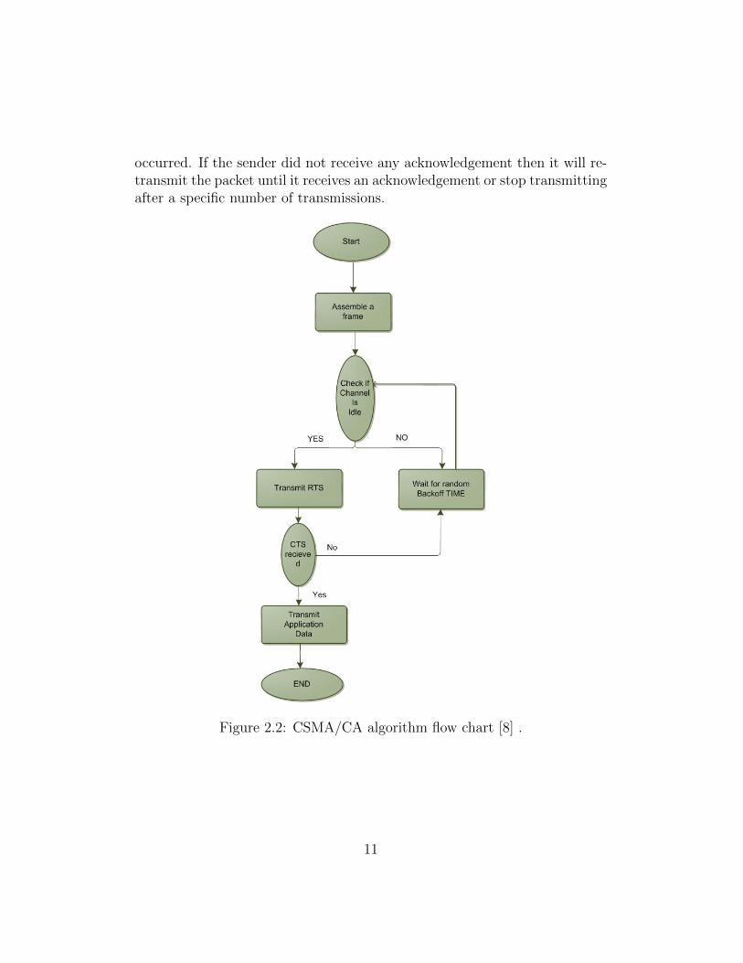
occurred. If the sender did not receive any acknowledgement then it will re-transmit the packet until it receives an acknowledgement or stop transmittingafter a specific number of transmissions.
Figure 2.2: CSMA/CA algorithm flow chart [8] .
11
2.3.2 Binary Exponential Backoff BEB
DCF is based on a CSMA/CA technique and employs a contention resolutionmethod, called Binary Exponential Backoff (BEB) in order to minimize theprobability of collisions. BEB reduces packet collisions due to the case of twoor more stations transmitting simultaneously [4]. Under BEB, the contentionwindow (CW) dynamically controls medium access and is doubled every timea station experiences a packet collision. Conversely, if a station successfullytransmits its packet, the CW is reset to the minimum value [3]. The backoffcounter for every station depends on the collisions that the packets haveexperienced in the past. The collision avoidance protocol procedures specifythat before transmitting, a station uniformly selects a random value for itsbackoff counter in the interval [0;Wi -1] where, ”Wi” is the current CW sizeand ”i” is the backoff stage [7]. The value of Wi is equal to Wi = 2i ∗ W ;i depends on the number of failed transmissions of a packet. At the firsttransmission attempt of a packet, W0 = CWmin = W that is the minimumCW size. If a packet collision occurs, Wi is doubled up to a maximum value,
Wm = CWmax = 2m ∗W, (2.1)
wherem = log2(CWmax/CWmin), (2.2)
identifies the number of backoff stages. Once Wi reaches CWmax; it willremain at this value until it is reset to CWmin after a successful packettransmission [7]. The DCF operation, shown in figure 2.3, works as follows,before a station start the transmission process; it has to sense the wirelessmedium. If the shared media is found idle for a minimum time equal to DIFS,the head-of-line MAC frame will be transmitted. Then the station entersinto backoff procedure and sets its backoff timer randomly within the rangeof Contention Window (CW). When the channel is sensed ”idle”, the backofftimer is decremented by one; when the medium is sensed ”busy” the backofftimer is frozen. When the backoff timer reaches zero, the station commencesthe frame transmission as the next consequence. When the delivered frame isreceived correctly, the receiver is required to send an acknowledgment (ACK)after a time equal to Short Inter Frame Space (SIFS). If no ACK is received,the sending station assumes either a collision or frame corruption, and thenit doubles its current CW, resets its backoff timer randomly, and retransmitsthe previous frame when the timer reaches zero again [4].
12

Figure 2.3: DCF operation [10] .
2.3.3 Disadvantages of DCF
Despite of its efficiency in avoiding packet collision, the legacy DCF still suf-fers from drawbacks in the performance. One of the problems is that thelegacy DCF cannot differentiate between corruptions happened in transmit-ting a packet and a collision in the packets. That issue affects the overallperformance of the system since the CW will be changed as there is a colli-sion while it could be a corruption. Another issue is fairness of transmittingpackets among the stations sharing the wireless medium.
2.4 Double Increment Double Decrement DIDD
BEB algorithm is used to reduce the probability of packet collisions but onthe other hand, it cannot eliminate collisions completely. Also, it suffers froma low throughput performance under high traffic load. The main reason forthat is because when the number of contending stations is high and a packetis being transmitted successfully after a number of collisions, resetting thecontention window CW to the minimum value will increase the probabilityof collisions [6]. From this problem, the idea of DIDD (Double IncrementDouble Decrement) came to gently decrease the CW after successful packet
13

transmissions and though enhancing the performance of the DCF.
2.4.1 DIDD Algorithm
DIDD is a backoff algorithm that works on enhancing the trends in the al-gorithm of the normal BEB since the normal BEB does not learn from thecollision experience and resets the CW to its minimum value after a success-ful packet transmission not taking into consideration the number of collisionsthe packet has encountered [6]. BEB works in a good manner when thereare only few stations competing on transmitting packets but when the num-ber of stations increases, the sudden reduction of the CW to CWmin willaffect the performance in a way that will lead to a degradation because itincrease the collision probability after every successful transmission. Thebackoff algorithm used in DIDD is used to have an easy decline of the CWafter a successful transmission of packets. In another word, if there is a colli-sion, DIDD acts the same as BEB and doubles the CW, though decrease theprobability of packet collisions. Meanwhile, if the packets were transmittedsuccessfully DIDD will reduce CW into half (CW/2), while BEB will reduceit to CWmin, in order to avoid future packet collisions [6]. Another enhance-ment in the DIDD algorithm is that when packets reach their maximumnumber of retransmission attempts will not be discarded as it goes in theBEB algorithm. The difference between DIDD and BEB scheme regardingthe algorithm used after a packet collision and after a successful transmissionis shown in figure 2.4 .
Figure 2.4: Difference between DIDD and BEB [6] .
14

2.5 IEEE 802.11e
In order to introduce Quality of service (QoS) to the performance of thestandard IEEE 802.11, an enhanced version was introduced called the IEEE802.11e. The IEEE 802.11e offers an enhanced level of assurance for consis-tent data delivery which introduced an improved QoS. IEEE 802.11e intro-duces fairness to stations where high priority traffic has a higher chance ofbeing sent than low priority traffic.
The access mechanism in the IEE802.11e is the Hybrid CoordinationFunction (HCF), which uses two modes the Enhanced Distributed ChannelAccess (EDCA) and the HCF Controlled Channel Access (HCCA). EDCA isa contention based Access Method, while HCCA is an optional polling basedaccess mechanism. EDCA is the enhanced version of the legacy DCF [12].
2.5.1 EDCA
EDCA has introduced a QoS to the WLAN by supporting priority service tostations. A four Access Categories (ACs),shown in figure 2.5, were added inorder to provide Prioritized QoS. These ACs provide delivery of the framesaccording to the user priority. The differentiation between priorities dependson the values of the AC parameters. These parameters are:
• Arbitrary Inter-frame space number (AIFSn): it is the minimum in-terval time between the medium of a WLAN becoming idle and thetransmission of a new frame.
• Contention Window (CW)
• Transmission Opportunity (TXOP) limit: it is the maximum time al-lowed for a QoS Station (QSTA) to transmit after obtaining a TXOP[12].
The Backoff time is calculated by a contention algorithm for each ACindependently and based on the AIFSn, a contention window and a randomnumber. The AC with the smallest backoff wins the internal contention andcontends externally to the wireless medium [12], see figure 2.6.
The only exception compared to the DCF algorithm is that in DCF thedeferral and backoff are constant while in the IEEE 802.11e the deferral andthe backoff are variables and the values are set according to the appropriateAC.
AIFS = SIFS + AIFSn ∗ aSlotT ime. (2.3)
15

Figure 2.5: EDCA in IEEE 802.11e [12] .
Figure 2.6: Backoff difference between EDCA and DCF [12] .
Where AIFSn depends on AC and the value of aSlotTime depends on thephysical layer of the IEEE 802.11e used. The Backoff procedure is uniformlydistributed between CWmin and CWmax [12].
Backoff = AIFS + random[CWmin : CWmax]. (2.4)
The coming chapter presents the simulation model and talks in details aboutthe simulation environment, showing some of the outcome.
16

Chapter 3
Simulation
NS2, Network Simulator 2, is an event driven network simulator launchedat the University of California at Berkeley. It supports different networkingprotocols like TCP, UDP, queuing management, and some traffic sourcing likeTelnet, CBR, and FTP. NS2 is written in C++ and OTCL, Object OrientedTool Command Language which was developed at Massachusets Institute ofTechnology [13].
3.1 NS2 Structure
Ns2 acts as a TCL interpreter where the end user should write the code inTCL and then pass it to NS2. NS2 is a packet-level simulator and essen-tially a centric discrete event scheduler to schedule the events such as packetreception and timer expiration. NS2 comes along with a simulation eventscheduler and network component object libraries and plumbing modules.
The term, plumbing, is referring here to the concept of plumbing thepossible data paths among the objects inside the network. The plumbingfacility is behind the strength popularity of NS2. Also, a main task for theprogrammer is to assign the start and end time for the traffic sources totransmit packets through the event scheduler.
The simulation output is a trace file, which includes all the detailed infor-mation of each packet. To analyze the trace file and conclude the results, aPerl script is used. Perl is designed for processing of text based data, eitherin files or data streams [15]. Perl reads the input a line at a time. A line isscanned for each pattern in the program, and for each pattern that matches,
17

the associated action is executed. The simulation results are sent to theNetwork animator (NAM) which is an animation tool for viewing networksimulation traces and real world packet traces. NAM supports topology lay-out, packet level animation, and various data inspection tools. The structureof NS2 is shown in figure 3.1.
Figure 3.1: Structure of NS2 [15].
3.1.1 The event scheduler
The event scheduler in NS2 is defined as a packet ID that is related to aunique packet with assigned finctionality time along with a pointer to theobject which will handle that event. The event scheduler main task is tokeep tracking of the elapsed simulation time and launch the queued eventsaccording to the required times [13]. Another usage of the event scheduler isbeing timer such as in case of transmitting two TCP packets with the samepacket number but with different NS packet ID. The network components arethe principal user of the event schedulers in packet-handling delay simulationor in timing issues. Figure 3.2 shows how every network component uses aunique event scheduler and handles only the events that it issued itself. Thedata path between the network objects is different from the event path [13].
18

3.1.2 NS2 and Split Object Models
In order to ensure the flexibility of the configuration and its efficiency, ns-2adopts the OTcl/C++ split object model which allows C++ and OTcl tointerpret and operate the data defined and also to link the C++ classes andOTcl classes. C++ is used to perform per packet action while OTcl is usedfor periodic or triggered action, and TclCL is used to link between C++ andOTcl.
Figure 3.2: NS2 C++/OTCL [15] .
Ns2 deals with two different kinds of work and for that it uses two pro-gramming languages (C++ and OTCL). A programming language that givesa detailed simulation of protocols and efficiently manipulates bytes, packetheaders and implements algorithms that runs over large data sets. Run-timespeed is more important than the turn-around time (run simulation, recom-pile, rerun). Another programming language that is easier to apply somechanges regarding the parameters, the configurations and the scenarios [15].In this case, iteration time (change the model and rerun) is more importantthan the run-time.
19

3.2 Simulation Scenario
The simulation is based on Ns2.34 where the legacy DCF is already defined.DIDD is implemented by applying some changes in the code and rewritingof the algorithm functions. On the other hand, EDCA is implemented byadding an extra patch and applying some changes in the code.
3.2.1 Simulation Assumptions
The assumptions made in this thesis are :
• Stations are in the transmission range of each other
• No hidden terminals
• Time is divided to slots and stations are synchronized to these slots
• Transmission can occur only at the beginning of the slot
• Ideal channel is assumed
• Frame loss is occurred only by collisions
• Frame length is the same for all stations
• Same data rate
3.2.2 Scenario
Two simulation scenarios are implemented, a simple one and another complexone. The simple scenario is based on an Ad hoc network consisting of 6 nodesfrom n(0) till n(5). The data rate is set to 11 Mbit/sec [13]. The idea of thescenario is to have nodes in motion in order to simulate the performance ofa network in motion. For the simple scenario, Nodes 0 and 4 are targetingnode 3 while nodes 2 and 4 are targeting node 1. Figure 3.3 shows a roughtopology of the simple network.
The complex scenario, shown in figure 3.4, was also implemented in orderto obtain more in depth analysis of DCF and its successors in case of largerwireless networks. So additional nine mobile nodes were added to the oldscenario. Where each of there of them is acting as a sink or receiver fortwo unique nodes. File Transfer protocol FTP application were chosen to
20

Figure 3.3: The Simple Network Topology .
be used. So now the network is consisting of fifteen mobile nodes: four ofthem are using CBR and six of them are using FTP. AODV is also set as therouting protocol. In this complex scenario, five nodes are moving to targetthe performance of the network in case of motion. The data rate was setto 11 Mbits/sec and the simulation time is also set to the standard of 900seconds [13].
The traffic generator used in the simulation is a CBR (Constant BitRate)traffic generator over TCP, which is generating traffic randomly bypicking up random node pairs as sources and destinations. The simulationtime is set to 900 seconds which is the standard simulation time for testingthe performance of wireless networks [13]. The routing protocol is set tobe AODV(Ad hoc On-demand Distance Vector Routing). AODV is a re-active routing protocol which means it starts a route to a destination onlyon demand. AODV does not need to know the complete path to the des-tination. In this case, nodes forward the packets to neighbor nodes of thedestination[14].
AODV has a unicast and a multicast routing capabilities. AODV is calleda distance vector routing protocol since it establishes a route to a destinationonly on demand. In AODV, the network is silent until a connection is needed.
21

Figure 3.4: The Complex Network Topology .
At that point the network node that needs a connection broadcast requestfor connection. Other AODV nodes forward this message, record the nodethat they heard it from, and create an explosion of temporary routes backto the needy node. When a node receives such a message and already has aroute to the desired node, it sends a message backwards through a temporaryroute to the requesting node. The node in need, begins using the route thathas the least number of hops through other nodes. Unused entries in therouting tables are recycled after a time [14].
After running the simulation, a simple plotting tool called GNUPLOTwas used in order to grab the observations. Gnuplot is a command-line pro-gram which is used to generate two- and three-dimensional plots of functions,data, and data fits.
At the beginning,the scenario was applied for the legacy DCF. As thelegacy DCF is already included in the NS2 as the initial function for thewireless LAN.
After that, the same scenario was applied for DIDD. In order to implementDIDD in Ns2, a change in the code was done. After a successful transmissionof data, a function called rst-cw() is called in order to reset the contentionwindows. The change was made in this specific function where when thisfunction is called it does not reset the contention window but it devides it
22

by two, so the value of CW0 will be:
CW0 =CW
2. (3.1)
A new patch was added to Ns2 to have the ability to implement the IEEE802.11e EDCA. The patch was developed by Sven Wiethlter and ChristianHoene at the Technical University of Berlin [17]. The patch replaces theoriginal MAC-802 11.cc in NS2 with a new 802.11e MAC layer access func-tionalities, and moves the corresponding physical layer functionalities, suchas carrier sense, transmission and reception of frames, out to two separatefiles [16]. The same scenario above was applied for EDCA and the resultswere conducted.
When each simulation is completed, NS2 produces an output file calledthe trace file. This file contains a detailed information about every packet wassent during the simulation time. The format of the trace file is very differentfrom wireless networks scenario to wired networks. In Wireless Networkscase, each row in the trace file presents a detailed information about a uniquepacket. The row consists of many fields. The first one defines the type ofthe action, whether it is sent or received or dropped packet. The second fieldstates the time that the action happened at. The next one defines which nodehosted the action. The fourth one defines which layer the action happenedat. It could be the application layer, the transport layer, or the physicallayer. Then the flags in case some flags of settings were defined in the code.The coming field contains the sequential number of the packet. The seventhfield defines the type of the packet whether it is a data streaming packet,routing packet, or link layer packet. Then the size of the packet according tothe layers because the size of the packet is different in the lower layers thanthe upper layers. Then one raw matrix contains the packet duration in theMAC layer, the source and destination MAC address, and the MAC type ofthe body. Another following array contains first the source node IP alongwith the port number. Then the destination IP followed by the header IPand the next hop IP.
By considering the following example:It can be interpreted as CBR data streaming packet with ID 900 and size
of 16 bytes was sent at the MAC layer at node 3 to node 0.A simple Perl script was developed to calculate the delivery ratio and
the average delay. This script investigates the trace file line by line. If thepacket is data streaming or CBR, it will check whether it is sent or received
23

Figure 3.5: Trace File format .
and then it will increment the relevant counter. So this script will count thetotal number of sent packets and the number of received packets. A simpleequation will produce the delivery ratio. Also the script reads in every linethe duration of each packet. The duration of each packet may be calculateddepending on more than one line since the line can be for a routed, queued,sent or received packets. The results are calculated as follows:
• Average delay is the summation of the delay of all packets divided bythe number of generated packets.∑nbrPackets−1
n=o Delay[n]
nbrPackets− 1(3.2)
• The delivery ratio is the number of received packets divided to thenumber of generated packets.
• The throughput is calculated using the following formula:
throughput =NbrRecievedBytes ∗ 8
SimulationT ime ∗ 1024Kbps. (3.3)
• The number of dropped packets is calculated as the number of packetsthat did not reach the receiver.
24

Chapter 4
Simulations Results
In the simulation scenario, a random environment was implemented. TheCBR traffic generators simulates voice calls in the real world. Also the nodemovement was introduced in the scenario in order to be more realistic. Thesimulation time is set to 900 seconds which is the standard time for network-ing simulation and analysis [13].
After running the simple scenario with the three different MAC protocols,three unique trace files were obtained with detailed information related tovery each packets. As mentioned in the previous chapter, three factors werechosen to analyze the results and deduce some states about the performanceimprovement.
Figure 4.1 shows the comparison between DCF, DIDD, and EDCA withrespect to the average throughput. There were two sinks in the simulationscenario: node 1 and node 3. The throughput at each node was measured.Then, the average throughput of the network is calculated by dividing thesum by two. The average throughput in DCF scenario was 0.77 Mbits whileit reached 1.33 Mbits in DIDD scenario. EDCA has achieved remarkableachievements by reaching an average throughput of 1.73 Mbits.
Figure 4.2 show the comparison between DCF, DIDD, EDCA with respectto the delivery ratio. As previously explained, the delivery ratio is the numberof received packets in percentage of the total transmitted packets. The legacyDCF achieved 74.2 , while the DIDD reached 74.4 and the EDCF exceededtill 76.4. So, it is noticeable that DIDD did not differ much from the legacyDCF and could not reduce the number of the lost packets. On the otherhand, EDCA has relatively reduced the number of lost packets by exceedingthe legacy DCF by the value 2.4 .
25

Figure 4.1: The Average Throughput .
Figure 4.3 shows the difference between between DCF, DIDD, and EDCAwith respect to the average delay in millisecond. The average delay wasexplained as the average of the transmission time of each packet that canbe read from the trace file. The legacy DCF had an average delay of 49.2millisecond, while DIDD has 39.8 millisecond. EDCA noticeably reduced theaverage delay time to 33.4 millisecond which can be seen as 32 improvement.
Figure 4.4 shows the comparison between DCF, DIDD, and EDCA withrespect to the average throughput in the complex scenario. There were fivesinks in the simulation scenario: node 1, node 3, node 7, node 10, and node11. The throughput at each node was measured. Then, the average through-put of the network is calculated by dividing the sum by five. The averagethroughput in DCF scenario was 0.15 Mbits while it reached 0.73 Mbits inDIDD scenario. EDCA has got better achievements by reaching an averagethroughput of 1.46 Mbits. Figure 4.5 shows the comparison between DCF,DIDD, EDCA with respect to the delivery ratio in the complex scenario.The legacy DCF achieved 0.70, while the DIDD reached 0.71 and the EDCFexceeded till 0.75. So, it is noticeable that DIDD did not differ much fromthe legacy DCF and could not reduce the number of the lost packets. On
26

Figure 4.2: The Delivery Ratio Figure 4.3: The Average Delay
the other hand, EDCA has relatively reduced the number of lost packets byexceeding a ratio of 75.
Figure 4.6 shows the difference between between DCF, DIDD, and EDCAwith respect to the average delay in the complex scenario. . The legacy DCFhad an average delay of 50.1 millisecond, while DIDD has 42.2 millisecond.EDCA noticeably reduced the average delay time to 37.3 millisecond.
By comparing the results of the two scenario, some observations can bededuced. The legacy DCF has much poorer performance in large networks.Also, Its delivery declined while its average delays sustained almost the sameperformance. The average throughput in case of DIDD has also decreasedby 44%. Its average delivery ratio declined by 4% while the average delayincreased by 2.4 milliseconds. The average throughput of EDCA in complexscenario reduced only by 0.27 Mbits. Its delivery ratio declined by less than2% and the average delay was raised by 4 milliseconds. In empirical view,the EDCA has proved much better performance than both legacy DCF andDIDD.
27

Figure 4.4: The Average Throughput.
Figure 4.5: The Delivery Ratio Figure 4.6: The Average Delay
28

Chapter 5
Conclusions
The Double Increment Double Decrement (DIDD) scheme slightly improvesthe performance of the the wireless network compared to the legacy DCF. Themain advantage is its simplicity since its based on an elementary conditionalprobability arguments. DIDD offers some enhancements to the performanceof WLANs but on the other hand, it attains higher packet delay values sinceit includes the time delay of the packets that otherwise should be discarded[6].
The IEEE 802.11e EDCA improves the overall performance of the WLANand it also offers some enhancements to the performance of high prioritytraffic. EDCA is still not that perfect since it is based on a random accesstechnology and it can not guarantee a quality level for high priority traffic.
Comparing the results of the average delay, throughput, jitter and thedelivery ratio of DCF, DIDD, and EDCA; The output results of EDCA haveshown better values and better performance but yet needs more research toachieve better Quality of Service (QoS).
Future work can be done by focusing on the enhancement of the through-put, decreasing the average delay and reducing disadvantages of performanceof EDCA. Though, improving packets transmission and eliminating packetsloss.
29

Bibliography
[1] Yu Zheng, Kejie Lu, Dapeng Wu, and Yuguang Fang, “PerformanceAnalysis of IEEE 802.11 DCF in Imperfect Channels,” Sep 2006..
[2] Dillip Kumar and Prof Bibhudatta Sahoo, “Performance Evaluation ofMAC DCF Scheme in WLAN,” Mar 2006..
[3] “IEEE Wireless LAN Medium Access Control (MAC) and Physi-cal Layer (PHY) Specifications,” (2007 revision). IEEE-SA., 12 June2007.10.1109/IEEESTD.2007...
[4] Andreadis, Alessandro Benelli, Giuliano Zambon, Riccardo, “PerceptualQuality of Internet Telephony over IEEE 802.11e Supporting EnhancedDCF and Contention Free Bursting,”, 19 March 2007....
[5] Kaveh Ghaboosi Student Member, IEEE, Matti Latva-aho, Senior Mem-ber, IEEE, Yang Xiao, Senior Member, IEEE, Babak H. Khalaj, Mem-ber, IEEE, “IEEE 802.11 Distributed Coordination Function ServiceTime and Queuing Delay Analysis using Parallel Space - Time MarkovChain,”, 2007....
[6] P. Chatzimisios, V. Vitsas, A. C. Boucouvalas and M. Tsoulfa., “Achiev-ing performance enhancement in IEEE 802.11 WLANs by using theDIDD backoff mechanism,”, 2007....
[7] S. Wietholter, C. Hoene, A. Wolisz , “Perceptual Quality of InternetTelephony over IEEE 802.11e Supporting Enhanced DCF and Con-tention Free Bursting,”,Berlin, September 27th, 2004....
[8] Miquel Oliver, Ana Escudero , “Study of different CSMA/CA IEEE802.11-based implementations,” Dept. Mat.Apl. i Telemtica, UniversitatPolitcnica de Catalunya (UPC), 1999....
30

[9] Behrouz A. Forouzan, “ MAC Sublayer, ” www.globalspec.com...
[10] Simon Soung, “ NS2 MAC 802.11, ” blog.chinaunix.net...
[11] Pablo Brenner, “A Technical Tutorial on the IEEE 802.11 Protocol , ”www.sss-mag.com...
[12] Prof. Rathnakar Acharya, Dr. V. Vityanathan, Dr. Pethur Raj Chellaih,“WLAN QoS Issues and IEEE 802.11e QoS Enhancement,”, 2010....
[13] Jae Chung, Mark Claypool, “ NS by Example, ” WPI, Worcester Poly-technic Institute...
[14] Ian D. Chakeres and Elizabeth M. Belding-Royer. ”AODV Routing Pro-tocol Implementation Design.” Proceedings of the International Work-shop on Wireless Ad Hoc Networking (WWAN), Tokyo, Japan, March2004
[15] Tommi Larsson, Yusheng Lui, “A Study of EDCA and DCF in MultihopAd Hoc Networks,”,Sweden, March 13, 2008..
[16] Sven Wiethlter, Christian Hoene , “ An IEEE 802.11e EDCA and CFBSimulation Model for ns-2, ” http://www.tkn.tu-berlin.de...
[17] Sven Wiethlter, Christian Hoene, “Design and Verification of an IEEE802.11e EDCF Simulation Model in ns-2.26,”,Telecommunication Net-works Group, Technische Universitt Berlin, November 2003..
31

Appendices
32

.1 Simulation-Scenario.tcl
Mac/802_11 set dataRate_ !1Mb
set val(chan) Channel/WirelessChannel ;# channel type
set val(prop) Propagation/TwoRayGround ;# radio-propagation model
set val(ant) Antenna/OmniAntenna ;# Antenna type
set val(ll) LL ;# Link layer type
set val(ifq) Queue/DropTail/PriQueue ;# Interface queue type
set val(ifqlen) 50 ;# max packet in ifq
set val(netif) Phy/WirelessPhy ;# network interface type
set val(mac) Mac/802_11 ;# MAC type
set val(nn) 15 ;# number of mobilenodes
set val(rp) AODV ;# routing protocol
set val(x) 800
set val(y) 800
# Creating simulation object
set ns [new Simulator]
#creating Output trace files
set f [open complexdcf.tr w]
$ns trace-all $f
set namtrace [open complexdcf.nam w]
$ns namtrace-all-wireless $namtrace $val(x) $val(y)
set f0 [open C_DCF_AT.tr w]
set topo [new Topography]
$topo load_flatgrid 800 800
# Defining Global Variables
create-god $val(nn)
set chan_1 [new $val(chan)]
# setting the wireless nodes parameters
$ns node-config -adhocRouting $val(rp) \
-llType $val(ll) \
-macType $val(mac) \
-ifqType $val(ifq) \
33

-ifqLen $val(ifqlen) \
-antType $val(ant) \
-propType $val(prop) \
-phyType $val(netif) \
-topoInstance $topo \
-agentTrace OFF \
-routerTrace ON \
-macTrace ON \
-movementTrace OFF \
-channel $chan_1 \
proc finish {} {
global ns f f0 namtrace# global variables
# Closing the trace files
$ns flush-trace
close $namtrace
close $f0
exec nam -r 5m complexdcf.nam & # Running the animator
exit 0
}
# Defining a procedure to calculate the througpout
proc record {} {
global sink1 sink3 sink7 sink10 sink11 f0
set ns [Simulator instance]
set time 0.5
set bw0 [$sink3 set bytes_]
set bw3 [$sink3 set bytes_]
set bw7 [$sink7 set bytes_]
set bw10 [$sink10 set bytes_]
set bw11 [$sink11 set bytes_]
set now [$ns now]
puts $f0 "$now [expr ($bw0+$bw3+$bw7+$bw10+$bw11)/$time*8/1000000]"
# Calculating the average throughput
34

$sink1 set bytes_ 0
$sink3 set bytes_ 0
$sink7 set bytes_ 0
$sink10 set bytes_ 0
$sink11 set bytes_ 0
$ns at [expr $now+$time] "record"
}
#Creating the wireless Nodes
for {set i 0} {$i < $val(nn) } {incr i} {
set n($i) [$ns node]
$n($i) random-motion 0 ;
}
#setting the initial position for the nodes
for {set i 0} {$i < $val(nn)} {incr i} {
$ns initial_node_pos $n($i) 30+i*100
}
for {set i 0} {$i < $val(nn)} {incr i} {
$n($i) set X_ 0.0
$n($i) set Y_ 0.0
$n($i) set Z_ 0.0
}
# making some nodes move in the topography
$ns at 0.0 "$n(0) setdest 100.0 100.0 3000.0"
$ns at 0.0 "$n(1) setdest 200.0 200.0 3000.0"
$ns at 0.0 "$n(2) setdest 300.0 200.0 3000.0"
$ns at 0.0 "$n(3) setdest 400.0 300.0 3000.0"
$ns at 0.0 "$n(4) setdest 500.0 300.0 3000.0"
$ns at 0.0 "$n(5) setdest 600.0 400.0 3000.0"
$ns at 0.0 "$n(6) setdest 600.0 100.0 3000.0"
$ns at 0.0 "$n(7) setdest 600.0 200.0 3000.0"
$ns at 0.0 "$n(8) setdest 600.0 300.0 3000.0"
$ns at 0.0 "$n(9) setdest 600.0 350.0 3000.0"
$ns at 0.0 "$n(10) setdest 700.0 100.0 3000.0"
$ns at 0.0 "$n(11) setdest 700.0 200.0 3000.0"
$ns at 0.0 "$n(12) setdest 700.0 300.0 3000.0"
35

$ns at 0.0 "$n(13) setdest 700.0 350.0 3000.0"
$ns at 0.0 "$n(14) setdest 700.0 400.0 3000.0"
$ns at 2.0 "$n(5) setdest 100.0 400.0 500.0"
$ns at 1.5 "$n(3) setdest 450.0 150.0 500.0"
$ns at 50.0 "$n(7) setdest 300.0 400.0 500.0"
$ns at 2.0 "$n(10) setdest 200.0 400.0 500.0"
$ns at 2.0 "$n(11) setdest 650.0 400.0 500.0"
#Creating receiving sinks with monitoring ability to monitor the incoming bytes
set sink1 [new Agent/LossMonitor]
set sink3 [new Agent/LossMonitor]
set sink7 [new Agent/LossMonitor]
set sink10 [new Agent/LossMonitor]
set sink11 [new Agent/LossMonitor]
$ns attach-agent $n(1) $sink1
$ns attach-agent $n(3) $sink3
$ns attach-agent $n(7) $sink7
$ns attach-agent $n(10) $sink10
$ns attach-agent $n(11) $sink11
# setting TCP as the transmission protocol over the connections
set tcp0 [new Agent/TCP]
$ns attach-agent $n(0) $tcp0
36

set tcp2 [new Agent/TCP]
$ns attach-agent $n(2) $tcp2
set tcp4 [new Agent/TCP]
$ns attach-agent $n(4) $tcp4
set tcp5 [new Agent/TCP]
$ns attach-agent $n(5) $tcp5
set tcp9 [new Agent/TCP]
$ns attach-agent $n(9) $tcp9
set tcp13 [new Agent/TCP]
$ns attach-agent $n(13) $tcp13
set tcp6 [new Agent/TCP]
$ns attach-agent $n(6) $tcp6
set tcp14 [new Agent/TCP]
$ns attach-agent $n(14) $tcp14
set tcp8 [new Agent/TCP]
$ns attach-agent $n(8) $tcp8
set tcp12 [new Agent/TCP]
$ns attach-agent $n(12) $tcp12
# Setting FTP connections
set ftp9 [new Application/FTP]
$ftp9 attach-agent $tcp9
$ftp9 set type_ FTP
set ftp13 [new Application/FTP]
$ftp13 attach-agent $tcp13
$ftp13 set type_ FTP
set ftp6 [new Application/FTP]
$ftp6 attach-agent $tcp6
37

$ftp6 set type_ FTP
set ftp14 [new Application/FTP]
$ftp14 attach-agent $tcp14
$ftp14 set type_ FTP
set ftp8 [new Application/FTP]
$ftp8 attach-agent $tcp8
$ftp8 set type_ FTP
set ftp12 [new Application/FTP]
$ftp12 attach-agent $tcp12
$ftp12 set type_ FTP
#connecting the nodes
$ns connect $tcp0 $sink3
$ns connect $tcp5 $sink3
$ns connect $tcp2 $sink1
$ns connect $tcp4 $sink1
$ns connect $tcp9 $sink7
$ns connect $tcp13 $sink7
$ns connect $tcp6 $sink10
$ns connect $tcp14 $sink10
$ns connect $tcp8 $sink11
$ns connect $tcp12 $sink11
# Defining CBR procedure with the required parametes
proc attach-CBR-traffic { node sink size interval } {
set ns [Simulator instance]
set cbr [new Agent/CBR]
$ns attach-agent $node $cbr
$cbr set packetSize_ $size
$cbr set interval_ $interval
38

$ns connect $cbr $sink
return $cbr
}
set cbr0 [attach-CBR-traffic $n(0) $sink3 1000 .015]
set cbr1 [attach-CBR-traffic $n(5) $sink3 1000 .015]
set cbr2 [attach-CBR-traffic $n(2) $sink1 1000 .015]
set cbr3 [attach-CBR-traffic $n(4) $sink1 1000 .015]
# Setting the begining and ending time of each connection
$ns at 0.0 "record"
$ns at 20.0 "$cbr0 start"
$ns at 20.0 "$cbr2 start"
$ns at 800.0 "$cbr0 stop"
$ns at 850.0 "$cbr2 stop"
$ns at 30.0 "$cbr1 start"
$ns at 30.0 "$cbr3 start"
$ns at 850.0 "$cbr1 stop"
$ns at 870.0 "$cbr3 stop"
$ns at 25.0 "$ftp6 start"
$ns at 25.0 "$ftp14 start"
$ns at 810.0 "$ftp6 stop"
$ns at 860.0 "$ftp14 stop"
$ns at 35.0 "$ftp9 start"
$ns at 35.0 "$ftp13 start"
$ns at 830.0 "$ftp9 stop"
$ns at 889.0 "$ftp13 stop"
$ns at 40.0 "$ftp8 start"
$ns at 40.0 "$ftp12 start"
$ns at 820.0 "$ftp8 stop"
$ns at 890.0 "$ftp12 stop"
$ns at 900.0 "finish"
# Runnning the simulation
puts "Start of simulation.."
$ns run
39

.2 NS2 modification for NS2 EDCF
The code modification in explained step by step in [17].
.3 NS2 modification for DIDD
Changes is done to the file mac-802_11.h and mac-802.11.cc
inline void rst_cw() { cw_ = phymib_.getCWMin(); }
inline u_int32_t getCWMin() { return(CW_ /2); }
.4 Perl code
#!/usr/bin/perl
use strict;
# Error Handling: Checking the command parameters
if($#ARGV<0){
printf("Usage: <trace-file>\n");
exit 1;
}
open(Trace, $ARGV[0]) or die "Corrupted TraceFile";
my $t = 0; # transmitting Counter
my $rc = 0; # Receiving Counter
while(<Trace>){
my @line = split; # Splitting the line to check it item by item
if($line[6] eq "cbr"){ # check if the packet is application one
if($line[0] eq "s"){ # check it if it is sent
$tc++;
}
if($line[0] eq "r"){ check if it is received
$rc++;
}
close(Trace);
if($rc > 0){
40

printf("Delivery ratio %f\n", $rc/$tc);
}
41