performance analysis of afpm generator · pdf fileperformance analysis of afpm generator...
TRANSCRIPT

PERFORMANCE ANALYSIS OF AFPM
GENERATOR DIRECT DRIVEN WIND TURBINE
WITH STORAGE SYSTEM
Thi Thi Soe1, Hla Myo Aung
2
1Renewable Energy Department, Myanmar Scientific and Technological Research Department, Ministry of
Science and Technology, Email: [email protected] 2Renewable Energy Department, Myanmar Scientific and Technological Research Department, Ministry of
Science and Technology, Email: [email protected]
Received Date: January 2, 2013
Abstract
Direct-drive type with no acceleration rare and the windmill blades attached to the disc surface of
Axial Flux Permanent Magnet generator (AFPM) realizes simple structure and omission of central
dynamic transformation achieves very high energy conversion efficiency of the generator. The
generator itself consists of two magnets rotors that return together directly coupled to the blades. In
this research study, one magnet rotor is on each side of the stator and each magnet rotor contains 16
Neodymim-Iron-Boron (NdFeB). The stator contains 12 coils wound with copper wire and cast into
plastic resin, in line with and between the paths of each magnet. The AFPM generator direct drive
wind turbine converts the mechanical energy by the rotating shaft as the wind pushing 3 wooden
blades into 3-phase alternating current (AC) electricity that varies in frequency. In order to get this
generated power into a battery bank, three-phase bridge rectifier is connected to the three terminals
of the machine. The alternator will start 48 volt charging batteries system at about 140 rpm in 4m/s
wind speed and reach rated output of 1.8 kW at 375 rpm in 10m/s wind speed. This machine is
specially designed for battery charging and it‟s probably quite useful and cost effective for remote
locations that are not connected to the national grids where conventional methods of energy supply
are expensive or impractical.
Keywords: AFPM Generator, Battery Charging, Bridge Rectifier, Direct-Drive Type, Wind
Speed
Introduction
Small-scale wind energy could help decrease our reliance on declining and costly supplies
of oil. Another benefit of wind energy is that, unlike oil, coal and nuclear energy, the wind
is not owned by major energy companies or controlled by foreign nations. Wind energy
can help nations reduce global warming and devastating changes in our climate. Wind is
also a free resource. The cost of wind is not subject to price increases. A typical small wind
turbine has rotor that is directly coupled to AFPM generator which produces electricity at
12/24/48 volt direct current for battery charging. AFPM machine is used direct driven
small wind generator application for stand alone system. This stand-alone tends to supply
power to private houses, farms and other remote area of Myanmar. This research of wind
generator is operated in a direct battery charging application where the wind generator is
directly connected to a rectifier-battery combination. In this study, 3Φ, 1.8 kW AFPM
generator for small wind turbine is constructed with the technical parameter of the
implemented design data.
ASEAN Engineering Journal Part A, Vol 4 No 1, ISSN 2229-127X p.48

Anatomy and Characteristics of AFPM Topologies
AFPM machines have been developed in a number of topologies, namely the single-sided
machine, the double-sided machine with twin external stators and internal rotor and the
double-sides machine with internal stator and twin external rotors. The double-sided
AFPM machine with the double outer PM-rotor has the highest torque production capacity
due to the higher volume of PM material used. The double-sided outer-rotor topology is
the coreless AFPM machine of choice for small-scale wind generator applications.
The AFPM machine is used in a direct-driven wind generator application which
requires a low operating speed. In order to maintain frequency at rotating speeds, high pole
numbers are required. The drawback of a low-speed direct-driven AFPM generator is that
it requires high torque which requires a larger diameter, which affects the material cost of
the machine. If the diameter of the wind generator is too large, it will disturb the airflow
around the turbine hub and have a negative effect on the cooling capabilities of the AFPM
generator.
In AFPM air-cored stator winding, the windings are not kept in position within iron
slots, but with the use of epoxy resin. Therefore, with the absence of stator teeth and the
stator back yoke there is no cogging torque and no iron losses in the stator. Slotless AFPM
machines can be regarded as high efficiency machines due to the absence of the rotor core
losses which are normally present in the rotor back yoke and permanent magnets. In
AFPM topology, permanent magnet material Nd-Fe-B is used. The magnetic field of the
AFPM is the axial flux direction. The magnets arranged in N-S-N-S pattern around the
circumference of the rotors. When opposite poles face each other, the path of the magnetic
flux travels from one magnet face, straight to the magnet face opposite. Then this travels
through the steel rotor plate to the next magnet and back across the gap to the coil of wire.
The field passing through this area is a “magnetic flux”.
The rotor of the AFPM machine consists of two interconnected steel disks with
permanent magnets attached on the outsides circumference on the inner surfaces of the
opposing rotor disks. The steel rotor disks are multifunctional, as the rigid steel
construction maintains the necessary air-gap length between the opposing magnet poles
while providing the flux return path between the rotor poles. As the iron losses in the rotor
are very small and can for all practical reasons be neglected, the rotor disks can be
manufactured from solid iron, as opposed to laminated iron. The combination of the
coreless stator and the permanent magnets, both having a permeability of close to unity,
creates a large effective air-gap. In order to maintain acceptable values of magnetic flux
within the large air-gap, a much higher volume of permanent magnet is required.
The permanent magnets can either be mounted on the surface of the rotor disks or be
embedded into the rotor disk. The AFPM generators discussed in this study are of the
surface-mounted topology. Surface mounting of permanent magnets is the preferred
placement type due to the ease of the manufacturing of the smooth rotor disks, thereby,
lowering the cost of the machine. Another advantage is that the surface-mounted
permanent magnets naturally act as fans which have a ventilation effect on the stator
windings at higher rotating speeds. The added cooling feature of the spinning permanent
magnets allow for higher stator current densities before excessive stator winding
temperatures damage or irreversibly demagnetize the permanent magnets. Besides, lower
centrifugal forces allows for the permanent magnets to be glued onto the surface of the
rotor disks, instead of requiring further mechanical means such as through- magnet
fastening screws when the direct-driven AFPM generator operates with low rotating speed.
ASEAN Engineering Journal Part A, Vol 4 No 1, ISSN 2229-127X p.49
In AFPM machines, there are various different pole shapes used, amongst which the
rectangular, circular and sector- shaped are the most popular. The rectangular permanent
magnet 16 pole shape is used in this study. The cost of permanent magnet is further
reduced as a result of the simpler manufacturing process of the rectangular shaped. A
popular coil shape for AFPM machines is the toroidal-shape coil wound around an iron
core. Due to the construction of the coreless AFPM machine it is possible to manufacture
the stator winding of the AFPM machines with the use of performance trapezoidal coils.
The advantage of the trapezoidal coil shaped is that it allows to maximum coil flux linkage.
The performed coils are packed in sequence, connected accordingly and placed in the
required physical position within the stator mould. The stator is cast with a composite
material of epoxy resin and hardener which provides the structural support required for the
flat, disk-shaped stator.
The concentrated coils of the non-overlapping stator winding lie entirely next to each
other in the same plane. Therefore, no bending of the end-windings is required during the
manufacturing process, reducing the length of the end-winding and reducing the total
volume of copper used. A reduction in copper results in a reduction in stator winding
copper losses and an increase in AFPM machine efficiency. Coils of wire are held steady
while the magnets spin past on the rotor in AFPM machine. Because the magnets were
arranged N-S-N-S, the direction of the field flips each time a magnet goes by. The set of 12
coils are wound for this AFPM study. The number of coils and magnet is matched to the
decision of the generating rating. The size and gauge of wire is selected to produce the
right voltage. Size and speed range of the windmill has been chosen, the selection of the
stator configuration can be proceed because the purpose of this machine is to charge
batteries.
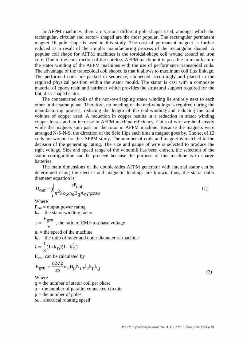
The main dimensions of the double-sides AFPM generator with internal stator can be
determined using the electric and magnetic loadings are known; thus, the stator outer
diameter equation is
3ηcosφmAgBsnwλk2π
outεPoutD (1)
Where
Pout = output power rating
kw = the stator winding factor
V
genEε , the ratio of EMF-to-phase voltage
ns = the speed of the machine
kD = the ratio of inner and outer diameter of machine
λ = )k)(1k(18
1 2DD
Egen, can be calculated by
dkpkalertNpBeω
ap
2q2genE
(2)
Where
q = the number of stator coil per phase
a = the number of parallel connected circuits
p = the number of poles
ωe = electrical rotating speed
ASEAN Engineering Journal Part A, Vol 4 No 1, ISSN 2229-127X p.50
Bp= the peak air-gap flux density
Nt = the number of turns per coil
re = the average adjust of the stator winding
la = the active length of the stator winding
kp = the pitch factor of the winding
kd = the distribution factor
In AFPM type of wind turbine, the design of the outer diameter is very important for
calculation of output power because the larger diameter is not reliable and stable for all the
system. According to the equation (1), the outer diameter of AFPM can be designed for
1.8kW. The RMS value of the sinusoidal phase voltage of the winding, E gen is calculated
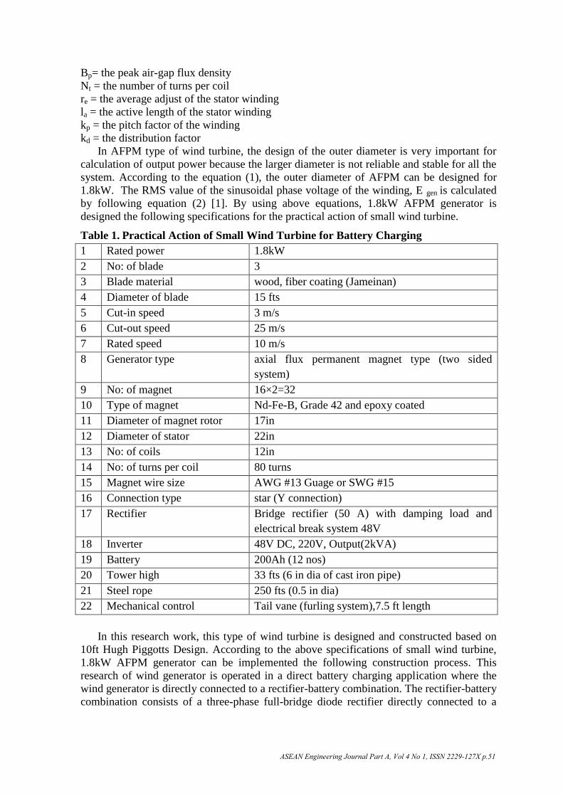
by following equation (2) [1]. By using above equations, 1.8kW AFPM generator is
designed the following specifications for the practical action of small wind turbine.
Table 1. Practical Action of Small Wind Turbine for Battery Charging
1 Rated power 1.8kW
2 No: of blade 3
3 Blade material wood, fiber coating (Jameinan)
4 Diameter of blade 15 fts
5 Cut-in speed 3 m/s
6 Cut-out speed 25 m/s
7 Rated speed 10 m/s
8 Generator type axial flux permanent magnet type (two sided
system)
9 No: of magnet 16×2=32
10 Type of magnet Nd-Fe-B, Grade 42 and epoxy coated
11 Diameter of magnet rotor 17in
12 Diameter of stator 22in
13 No: of coils 12in
14 No: of turns per coil 80 turns
15 Magnet wire size AWG #13 Guage or SWG #15
16 Connection type star (Y connection)
17 Rectifier Bridge rectifier (50 A) with damping load and
electrical break system 48V
18 Inverter 48V DC, 220V, Output(2kVA)
19 Battery 200Ah (12 nos)
20 Tower high 33 fts (6 in dia of cast iron pipe)
21 Steel rope 250 fts (0.5 in dia)
22 Mechanical control Tail vane (furling system),7.5 ft length
In this research work, this type of wind turbine is designed and constructed based on
10ft Hugh Piggotts Design. According to the above specifications of small wind turbine,
1.8kW AFPM generator can be implemented the following construction process. This
research of wind generator is operated in a direct battery charging application where the
wind generator is directly connected to a rectifier-battery combination. The rectifier-battery
combination consists of a three-phase full-bridge diode rectifier directly connected to a
ASEAN Engineering Journal Part A, Vol 4 No 1, ISSN 2229-127X p.51

battery bank. When rectifying the 3-phase power so that DC battery is charged, the current
is also much smoother for electrification in rural area.
Construction Feature of Direct Driven Wind Turbine
In this research work, three-phase axial flux permanent magnet (AFPM) generator direct
driven wind turbine is constructed for battery charging system in wind power application
in the rural electrification. . The arrangement of suitable machine is produced according to
the calculation of technical design parameter. To install 1.8 kW wind turbine, the
following procedure should be done 1.Magnet rotor 2.Casting stator 3.Assembly of the
alternator 4.Blades 5.Tail and 6.Raise the wind turbine step by step:
Magnet Rotors
Each magnet rotor is built on a steel disk made of magnetic material. The disk has holes to
mount it to the hub. Alignment of the rotors is critical in the operation of the alternator;
they must always go together the same way with alternating magnetic poles facing one
another. The first magnet is placed on the bottom magnet rotor. The template is pinned to it
and made of wood. But the magnet is strongly attracted to the steel disk [8]. There are 16
magnetic blocks (Nd-Fe-B, Grade 42) on each rotor and size of the one magnetic block is
3in× 1in× 0.5in. The 16 magnets for each disk need to be spaced around the disk with
alternating poles facing up to adjust the polarity (N S N S). The magnet rotors dropped into
the mould carefully. Then fiberglass resin is poured into the mould and over the tops of all
the magnets. When the resin is completely setup, the rotor can be removed from the mould.
Making magnet rotor is completely finished according to the construction procedure as
shown in Figure 1.
Figure 1. Construction of rotor discs
Casting Stator
The stator is the very important part of the wind turbine. It describes how to wind the coils
of enameled copper wire, and cast them in resin, using the jigs and moulds. This copper
wire has been coated with a very thin layer of insulating material. This means that when it
is wound into coils, the individual coils do not short-circuit one another where they touch.
In order to make an electrical contact with magnet wire, it is necessary to either scrape or
burn off the coating to expose the copper wire inside. The reel of winding wire is mounted
on an axle, then in line with the coil former. The wire should form an “S” bend as it winds
onto the coil. The first turn lies against the cheek piece on the side where the tail comes
out. The other turns lie against each other neatly, without crossing over. The coil is built up
in even layers and the number of turns is counted carefully [8].
ASEAN Engineering Journal Part A, Vol 4 No 1, ISSN 2229-127X p.52

In this study, there are 80 turns per coil and totally 12 coils. When the coil is
completed, a piece of sticky tape is passed under the coil on both sides and it is bind
tightly. The coils are soldered together and then a copper crimp is crimped on to add better
conductivity. Then, the coils is closed the mould, and when it has cured, the stator comes
out as one big disk with the coils encapsulated inside. All of the internal electrical
connections were made in advance. Either they selected one particular 3-phase connection
arrangement, or they have enough wires coming out to allow some external connection
changes. A more elegant solution is to wire up the coils for 3-phase operation. The
selection of size and gauge of wire (AWG#13gauge or SWG#15guage) are chosen, and
then the voltage is clamped to a specific value, 48V, depending on the charging system.
The selection of wire size allows the required current of AFPM design. The arrangement of
the coils is a star-shaped pattern in the flat mould. The coils also have fiberglass Matt
below them and small pieces of scrap fiberglass super glued to the coils, this is to prevent
them, individual wires from vibrating against one another from moving when fiberglass
resin is poured into the mould. C clamps are put on each sides of the mould to be tightened
until the resin is hard. While it is a bit flexible, C clamps are removed then; the stator is
removed from the mould. The casting stator is done the following steps as shown in Figure
2.
Figure 2. Stator coils casting from the mould
Assembly of Alternator
After finishing the magnet rotor and the stator, the alternator is assembled finally from all
the finished parts. The front rotor is raised safely and back off the alternator if necessary.
Each rotor also has a small mark (a divet made with a drill bit) so that the two rotors can be
aligned properly. The nuts/washers are used between the magnet rotors are the same high.
The back magnet rotor is taken and turned it so that the magnets face down on the beach.
The back of the hub is taken and put into the hole in the magnet rotor, such that the ends of
studs are poking into the 4 holes. The back magnet rotor is pickup by the studs and placed
it onto the spindle, up against the back bearing, and then the front bearing is inserted. The
washer is placed in front of the bearing, and then tightens the nut over the bearing. The
length of the airgap is 4mm gap clearance between the magnets and the stator, on both
sides. Next, the stator is mounted to the machine. Putting the assembly onto the wind
turbine, the studs should be fitted through the holes in the stator bracket. The back nut can
be adjusted with the fingers and set an approximately airgap between the stator and magnet
rotor [8]. The front magnet rotor is picked up by the jacking screws and placed it over the
studs sticking out the alternator. At this point, the alternator is assembled as shown in
Figure 3.
ASEAN Engineering Journal Part A, Vol 4 No 1, ISSN 2229-127X p.53

Figure 3. Alternator apparatus
The performance of alternator can be got according to run and measured DC voltage.
At around 140 rpm, this alternator will be produced „average‟ battery voltage. By using the
tachometer, v/rpm is tested to output through a rectifier and measured DC voltage at no
load condition as shown in Figure 4.
Figure 4. Relation between rpm and DC voltage of the alternator
The battery load is connected to rectifier output terminal. When the charging voltage
will rise to a peak level (about 10% above the battery‟s standard voltage, 48V) about rated
rpm, the current produced. In this test, higher wind speeds, the prop turns much faster and
provides more energy to overcome the heavy load, upwards of 1.8 kW.
Blades
The blades are also one of the important parts in the wind turbine that drives the generator.
The blades are made of wood because it‟s strong, lightweight, and reasonably inexpensive
and resist rot. These wind turbine blades have a simple airfoil like airplane wings. The
blades are twisted along their length this means that the blade pitch varies from shallow at
the tips to steep at the roots to approximate the correct angle of attack to the wind because
the tips of the blades are moving faster than the roots [7]. These blades are designed to run
at the tips speed ratio (TSR) between 6 and 7, and matched to the alternator. According to
the blade design, the diameter of blade is 15ft. The blade construction procedure is built
and referred by Hugh Piggott Design. The blades are coated with a few thick coating of
boiled linseed oil to protect the humid environments. The following Figure. 5 can be seen
how to construct the blades of wind turbine.
ASEAN Engineering Journal Part A, Vol 4 No 1, ISSN 2229-127X p.54

Figure 5. Making of Blades
Tail
The tail consists of three pieces: The tail boom, the tail bracket and the wooden tail vane.
The tail boom is a bit over 7.5 feet long, fabricated from steel pipe and steel stock. The tail
vain is made from high quality 3/8 in thick birch plywood to be strong, light weight and
resists fatigue cracking. Since it is wooden, it should be treated generously with linseed oil,
paint or stain to protect it from the elements. The hardware is supplied, and consists of 6 ×
5/16-18 bolts with washers, lock washers, and nuts use to attach the wooden tail vane to
the tail bracket. The assembly of tail can be seen as shown in Figure 6. The machine will
fold up and “furl” to reduce the effective swept area of the blades [7]. This protection
system called a “furling tail” is very simple in that it works simply by the geometry of the
machine‟s frame, requires no mechanical component like springs that can break, and
simply allows gravity to return the wind turbine back to normal operating position when
the wind drops back to normal levels (below 25m/s).
Figure 6. Tail vane bolted to the tail boom
Raise the Wind Turbine
In raising the tower, height of 33 fts and 6 in dia of cast iron pipe, the first step is to get the
machine up on the tower. The tower top has a stub of 2 ½in pipe, with a thick flat „washer‟
welded on the end. There is a plastic bushing on top of that, and then the machine simply
slips over the top of the tower and rests on the plastic bushing. According to this turbine
design to be available and flexible, the best standard wire grade (10 AWG) is selected for
the tower wiring. The wire goes straight through the tower, up through a hole in the wind
turbine, so as the machine turns the wire can twist. At the bottom of the tower there is a
heavy 3 prong locking plug that can be unplugged to occasionally allow the wire to untwist
if necessary. Then it is completely assembled and ready to go on the end of the tower.
In this position, the blades are balanced to be fitted to the alternator. To balance the
blades the heavy part is turned to the bottom (6 O‟clock). Then the heavy side is lifted to
the 3 O‟clock (or 9 O‟clock) position and added weight opposite it, until it seems to be
balance. These blades come out almost perfectly to add the hub [7]. There are two 6in
diameter steel hubs included, and one has a hole in the centre so that it can fit over the
grease cap on the alternator. The rotor will be clamped between these two hubs. The hub is
mounted with the hole on the alternator. Then the rotor is fitted to the alternator. The last
steel hub is put on over the blades. Each stud should get one lock washer and one nut to be
tightened. These blades are fastened tightly to the alternator and balanced while on the
tower stub in the lowered position. Before raise the tower up, he tail is fitted as a tilt up the
tower. After finishing the checking of the apparatus wind turbine, the tower is raised
slowly and gently adjusting the guy wires, turnbuckles, and etc. and tighten if needed. This
test raising tower procedure is shown in Figure 7.
ASEAN Engineering Journal Part A, Vol 4 No 1, ISSN 2229-127X p.55

Figure 7. Preparation to raise the wind turbine
Test Result
The implementation process of small wind turbines is installed between Shwe Thar
Layaung Mountain and Waibu Mountain, Kyaukse and tested within one week. This
research work is tested at there in the winter so that the wind speed can get about below
5m/s. Therefore, this research time, the relationship between wind speed and charging
current is shown in below the graph, Figure 8.
Figure 8. Relation between wind speed (m/s) and charging current (A)
In this research work, the cut in speed is needed about 10 m/s according to the design
parameter of 1.8 kW wind turbine construction and the rated speed is needed at least 10
m/s to get the rated power. This system is designed to charge a bank of batteries. The
inverter turns the battery voltage into AC that household appliances and lights can be used.
When the wind starts to blow and turns the blades at 2 m/s, the battery starts to be charged
with charging current, 2A. At the rated wind speed 10 m/s, the charging current is 30A to
be charged the battery bank using with 200Ah battery connected to 4 series 3 parallel. As a
result of this research work, the battery bank can be charged with 13.5A at 10m/s. If the
battery is charged with the rate of charging current (13.5A), the no; of 20 fluorescents, four
feet, is lighted about 4hr. On the other hand, if the location and the wind speed get better,
the higher charging current can stored to the more batteries attachment. Thus, if this
research wind turbine can be installed at the place which is situated at the average wind
speed is about 10 m/s, the charging current can be got the higher to the point at 30A to that
the four feet fluorescents (40Watt) is lighted and used about 50nos: in a remote building
ASEAN Engineering Journal Part A, Vol 4 No 1, ISSN 2229-127X p.56

with no power at all. The total power consuming power is 2 kW at the wind speed (10
m/s). The result detail data can be seen as shown in Figure.9.
Figure 9. Relation between wind speed (m/s) and power (Watt)
In accordance with the performance graph in Figure .9, the output power of AFPM
generator is 144W at the initial state (3m/s). When the wind speed gradually increase from
3m/s to 10m/s, the power also increase to about 1.62 kW. As these power data are
measured at battery load side, the generator generates to power output more than the rated
power, 1.62kW. If the cable loss is considered, the generator output can generate to 1.8kW
approximately. On the other hand, the calculation of wind turbine output can produce 3kW
according to the design at the rated wind speed 10m/s. In addition, when the output power
of battery load (1.8kW) including cable loss is ratio to the input power of wind turbine
(3kW) neglecting drive train losses, the overall efficiency is 60%. This type of wind
turbine has not seen in Myanmar wind turbine market. The efficiency of other wind
turbines can‟t be also found out in the technical data. To describe efficiency test data is
difficult in comparison to the existing commercially available wind turbines. Therefore, the
performance research work can be analyzed in the generator output for home lighting
system. The purpose of this construction of small-scale wind power system is not only to
get electrification but also to use cheaply for rural people. Therefore, it can supply the
energy requirements of Myanmar from one point.
Conclusions
In Myanmar, 70% of population lives in the rural areas. Therefore, this project work tends
to the rural electrification system for promoting the living standard and improving the
economy status of rural area by using wind energy. This research work of wind turbine
design is inexpensive and easy to construct for rural area because of homemade design.
However, the more output power mainly depends on the quality of the permanent magnet
type if so the more expensive of generator construction cost. Therefore, if the price of the
magnet can be got inexpensively in local area, Myanmar, this AFPM type of generator is
most suitable and variable for using the home lighting system in remote area.
For the cost benefit, this type of wind turbine does not need many construction area and
many labours cost to install it. To construct this wind turbine, all the equipments and
peripheral can be easily bought within local market and also less maintenance. The blades
made of wooden blades named Jameina which is easy to find, light, good strength and
cheap instead of teak. Especially, this turbine is quite easy to construct, operate and
maintain by users with a little technical experience. The whole cost for this type of wind
ASEAN Engineering Journal Part A, Vol 4 No 1, ISSN 2229-127X p.57

turbine is about $ 1570 without battery bank. The price can be able to construct to use
electricity cheaply for home lighting in rural area.
On the other hand, there are mainly two types of existing small scale wind turbine
technology such as axial type and radial type. Comparing to radial type, the cost benefit
per kW is not so different. The other comparing facts on advantage and disadvantage are
many points. However, the main point of the selecting this type is direct driven at low wind
speed. Direct driven operation is performed in order to minimize the mechanical losses in
the system by eliminating the use of gearbox. By removing the gearbox from the system,
the direct driven system can achieve higher performance with mass compared to a
generator gearbox combination. Moreover, this small wind turbine is more economical
than diesel engines for rural people in remote areas. By studying this research work, wind
power system is one type of renewable energy and small wind power system is widely
used as home-use system for rural electrification in low wind site, Myanmar.
References
[1] W. Rossous, Analysis and Design of AFPM Wind Generating System for Direct
Battery Charging Application, MSc Eng, Electrical and Electronic Engineering,
University of Stellenbosch, 2009.
[2] T.F. Chan, and L.L. Lai, “An Axial flux permanent-magnet synchronous generator for
a direct-coupled wind turbine system”, IEEE Transactions on Energy Conversion,
Vol. 22, No. 1, March 2007.
[3] Garrison F. Price. “Design and testing of a permanent magnet axial flux wind power
generator”, The 2008 IAJC-IJME International Conference, ISBN 978-1-60643-379-9.
[4] G. Tomassi, M. Topor, F. Marignetti, and I. Boldea, "Characterization of an axial flux
machine with non-overlapping winding as a generator", Electro Motion, Vol.13, pp.
73-79, 2006.
[5] A. Parviainen, and P. Kontkanen, Axial Flux Permanent Magnet Generator for Wind
Power Applications, Flux Magazine, pp.4-5, 2005.
[6] Bumby, J.R. Martin, M.A. Mueller, E. Spooner, N.L. Brown, and B.J. Chalmers,
"Electromagnetic Design of Axial Flux Permanent Magnet Machines", IEEE Proc. on
Power Applications, Vol. 151, No. 2, pp. 151-160, March 2004.
[7] “A Successful 17ft Wind Turbine Design by Dan Bartmann”, Available: www.other
power.com. [Accessed: December, 2010]
[8] “Hugh Piggott‟s Popular Design Manual”, Available: www.scoraigwind.com.
[Accessed: June, 2009]
ASEAN Engineering Journal Part A, Vol 4 No 1, ISSN 2229-127X p.58