afpm driving octane in an abstract - w. r. grace and … catalysts... · afpm 17‐75 driving...
TRANSCRIPT
AFPM 17‐75 Driving Octane in an Ultra‐Low Sulfur Gasoline Market
Andy Huang, Technical Service Representative, Grace Catalysts Technologies Gary Cheng, Technical Sales Manager, Grace Catalysts Technologies Ann Benoit, Technical Service Leader, Grace Catalysts Technologies
Bob Riley, Marketing Manager, Americas, Grace Catalysts Technologies
Abstract
Over the last two decades the refining industry has weathered a storm of volatile market conditions and increasingly stringent fuels regulations. These events and other variables have created a market environment that requires flexibility. The most flexible unit in a refinery is the FCC. Refiners need flexibility to operate with a dynamic feed slate of varying quality as well as flexibility to produce a wide range of products to meet market demand. In North America refiners are now, or will soon be, tasked with meeting challenging ultra‐low sulfur gasoline regulations (Tier 3). For many refineries meeting the sulfur limits will require operating adjustments, catalyst formulation changes, and/or capital investment. For others, the ABT credit trading program can provide a measure of relief for a fairly brief period of time. Many operating strategies that reduce sulfur may reduce gasoline octane, which is often undesirable due to refinery octane requirements. Incremental production from the alkylation complex can accomplish various goals; high octane value and low sulfur gasoline blend stock that compensates for octane loss due to more severe gasoline hydrotreating.
In this paper we will discuss octane fundamentals, the specifics of the Tier 3 regulations, and visit a number of refinery case studies and operating strategies for preserving octane, maximizing alkylation rates, and reducing sulfur to maintain regulatory compliance. Further, we will illustrate the value in each operational or catalytic route discussed using an example of a 50kbpd refinery against recent U.S. economics1.
Octane Drivers
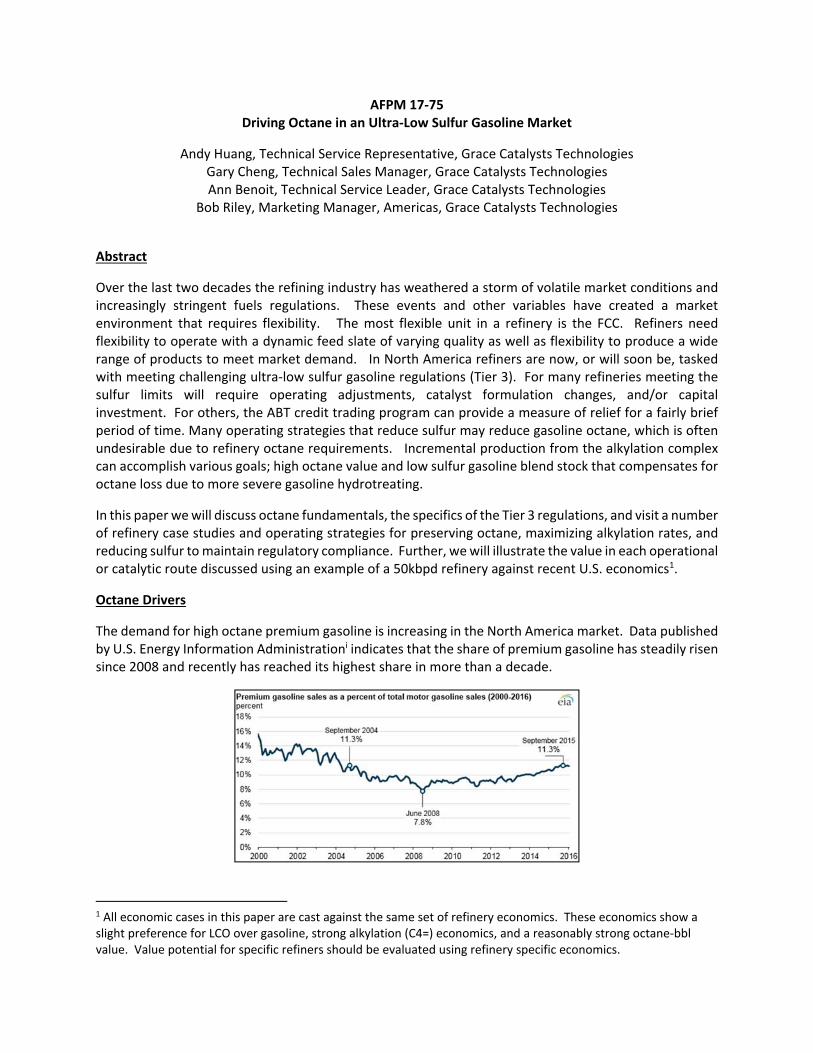
The demand for high octane premium gasoline is increasing in the North America market. Data published by U.S. Energy Information Administrationi indicates that the share of premium gasoline has steadily risen since 2008 and recently has reached its highest share in more than a decade.
1 All economic cases in this paper are cast against the same set of refinery economics. These economics show a slight preference for LCO over gasoline, strong alkylation (C4=) economics, and a reasonably strong octane‐bbl value. Value potential for specific refiners should be evaluated using refinery specific economics.
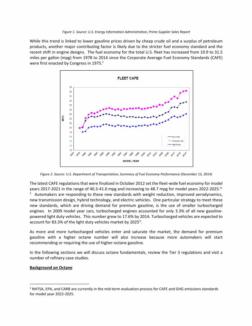
Figure 1. Source: U.S. Energy Information Administration, Prime Supplier Sales Report
While this trend is linked to lower gasoline prices driven by cheap crude oil and a surplus of petroleum products, another major contributing factor is likely due to the stricter fuel economy standard and the recent shift in engine designs. The fuel economy for the total U.S. fleet has increased from 19.9 to 31.5 miles per gallon (mpg) from 1978 to 2014 since the Corporate Average Fuel Economy Standards (CAFE) were first enacted by Congress in 1975.ii
Figure 2. Source: U.S. Department of Transportation, Summary of Fuel Economy Performance (December 15, 2014)
The latest CAFE regulations that were finalized in October 2012 set the fleet‐wide fuel economy for model years 2017‐2021 in the range of 40.3‐41.0 mpg and increasing to 48.7 mpg for model years 2022‐2025.iii, 2 Automakers are responding to these new standards with weight reduction, improved aerodynamics, new transmission design, hybrid technology, and electric vehicles. One particular strategy to meet these new standards, which are driving demand for premium gasoline, is the use of smaller turbocharged engines. In 2009 model year cars, turbocharged engines accounted for only 3.3% of all new gasoline‐powered light duty vehicles. This number grew to 17.6% by 2014. Turbocharged vehicles are expected to account for 83.3% of the light duty vehicles market by 2025iv.
As more and more turbocharged vehicles enter and saturate the market, the demand for premium gasoline with a higher octane number will also increase because more automakers will start recommending or requiring the use of higher‐octane gasoline.
In the following sections we will discuss octane fundamentals, review the Tier 3 regulations and visit a number of refinery case studies.
Background on Octane
2 NHTSA, EPA, and CARB are currently in the mid‐term evaluation process for CAFE and GHG emissions standards for model year 2022‐2025.

Octane is a relative measure of knocking characteristics of a fuel in an internal combustion engine. In an internal combustion engine, the normal combustion process is initiated by a timed external spark in which the combustion flame moves across the chamber uniformly. Knocking occurs when the fuel auto‐ignites ahead of the flame front (premature combustion, which may be started by any hot surface), causing shock waves against cylinder surfaces. The octane number of gasoline provides an indication of this knocking characteristic. The higher the octane number, the higher the fuel’s resistance to auto‐ignition. High octane fuel is therefore often recommended or required for turbocharged engines, as turbocharging increases cylinder pressure and compression ratio, which increases the tendency for auto‐ignition. For any given fuel, the octane number is defined as the volume percent of iso‐octane mixed with n‐heptane to match the knock characteristics of the fuel being tested.
The “true” method for measuring octane number is to use an Octane Engine at constant speed with
varying compression ratios to achieve standard knock intensity of reference fuel. Research Octane
Number (RON) is measured at 600 RPM with 60°F air/fuel mix to mimic city driving and Motor Octane
Number (MON) is measured at 900 RPM with 300°F air/fuel mix to mimic highway driving. The downsides
of this method are the lower reproducibility and the high cost associated with the test since this method
requires a large fuel sample. There are other methods that measure the molecular types in the gasoline
to determine the octane number. Some of these methods include NMR analysis, Fluorescent Indicator
Absorption, Near‐Infrared Spectroscopy, and Gas Chromatography. The table and chart below illustrate
the octane numbers for different hydrocarbon molecules. Aromatic and olefinic molecules both have high
RON and MON values, followed by naphthenes, iso‐paraffins, and then paraffins with the lowest octane
value. Octane Sensitivity, defined as the difference between RON and MON, can be high for olefins and
aromatics, and responsible for the familiar “gap” between RON and MON of gasoline. Paraffins exhibit
excellent sensitivities, but tend to have lower overall octane, which is especially true for long straight‐
chained paraffins as shown in Figure 3.
Table 1. Examples of Structural Effects

Figure 3. Octane Trends by Hydrocarbon Type. Data from API Research Project 45.
Maximizing Octane in a Conversion Refinery
The first step in moving toward a maximum octane operation is to understand the octane contribution of different streams to the refinery gasoline pool. The schematic below shows simplified refinery gasoline routings for a typical conversion refinery with several streams contributing to the overall gasoline blending pool. In order to maximize octane in the gasoline pool, refiners typically rely on models to optimize gasoline blending, while taking into consideration both physical and performance characteristics such as RVP, sulfur, benzene, olefins, aromatics, and octane. Maximizing the production of high octane streams such as alkylate and reformate and also making incremental octane improvements on FCC naphtha (Fluid Catalytic Cracking Unit) are critical to maximizing octane in a conversion refinery. FCC naphtha is the largest volume stream in the gasoline pool, as shown below in Figure 5.
Figures 4 & 5: Naphtha Routings and Octane Contribution of Various Streams
Maximizing Octane in an Ultra‐Low Sulfur Environment
Tier 3 regulations for lower gasoline sulfur will create challenges around maximizing octane, as many refiners will turn to higher gasoline post‐treatment severity for increased desulfurization, which will negatively impact octane. Under the new Tier 3 regulations, refiners are required to produce gasoline with an annual average sulfur content of ≤ 10 ppm, with a maximum gasoline sulfur cap at the refinery gate of ≤ 80 ppm. FCC naphtha is the main “problem stream,” as it comprises 40‐50 vol% of finished gasoline and contributes to 80‐90% of the total sulfur in the refinery gasoline pool.

The pie chart below, which is based on a recent survey, illustrates how North America refiners are meeting the Tier 3 regulations. Some refiners are already compliant or have purchased credits out to 2019‐2020. Some refiners have switched to a light/sweet crude slate, but this limits the feed flexibility and comes with a higher cost. Catalytic solutions such as Grace’s Gasoline Sulfur Reduction (GSR®) Technologies convert sulfur molecules to H2S in the FCC reactor, thereby reducing the sulfur ending up in FCC naphtha. There are also post‐treatment technologies designed to preserve gasoline octane by either removing sulfur selectively or by combining and concentrating sulfur molecules into a distillate stream. These post‐treatment technologies often require additional capital investment by the refiners.
Figure 6: Industry Survey on Meeting Tier 3 Regulations
The majority of refiners are meeting the regulations by increasing hydrotreating severity either with pre‐treating FCC feed or post‐treating FCC naphtha. This option increases the refinery H2 consumption and reduces the run length of these hydrotreaters. For some refiners, pre‐treating FCC feed is still not sufficient and can sometimes present a heat balance challenge for the FCC unit. While post‐treating is effective for reducing the sulfur content, it saturates aromatics and olefins resulting in octane loss in the FCC naphtha. This can be exacerbated at refineries that consume an increased diet of shale‐derived crudes, which are naturally light and produce low sulfur, but also low octane, gasoline. If the majority of refiners are faced with octane loss due to increasing hydrotreating severity and refinery feed choices, what options do these refiners have to maximize gasoline octane in this ultra‐low sulfur environment? The rest of this paper will examine case studies to highlight a few different options around the FCC units for maximizing overall refinery octane:
Case 1: Feed and operational changes to maximize LPG olefins to Alkylation Unit and improve octane
Case 2: Undercutting FCC naphtha to reduce post‐treat requirement and improve octane
Case 3: Catalytic solution to maximize LPG olefins to Alkylation Unit and improve octane
Case 4: Additives to boost LPG olefins to Alkylation Unit and improve octane
Case 5: Gasoline Sulfur Reduction (GSR®) Technology to reduce post‐treat requirement and preserve octane
Case 6: Combining multiple approaches
A generic price set is applied to these case studies to illustrate the effectiveness and the profitability of each approach. This price set places a high value on LPG olefins (alky feed) and octane barrels, with a slight preference for LCO over gasoline.
Case 1: Feed and Operational Changes
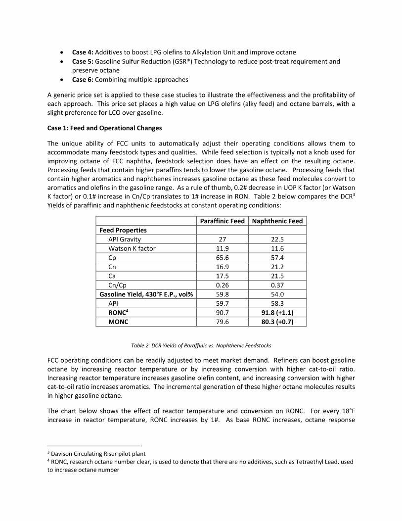
The unique ability of FCC units to automatically adjust their operating conditions allows them to accommodate many feedstock types and qualities. While feed selection is typically not a knob used for improving octane of FCC naphtha, feedstock selection does have an effect on the resulting octane. Processing feeds that contain higher paraffins tends to lower the gasoline octane. Processing feeds that contain higher aromatics and naphthenes increases gasoline octane as these feed molecules convert to aromatics and olefins in the gasoline range. As a rule of thumb, 0.2# decrease in UOP K factor (or Watson K factor) or 0.1# increase in Cn/Cp translates to 1# increase in RON. Table 2 below compares the DCR3 Yields of paraffinic and naphthenic feedstocks at constant operating conditions:
Paraffinic Feed Naphthenic Feed
Feed Properties
API Gravity 27 22.5
Watson K factor 11.9 11.6
Cp 65.6 57.4
Cn 16.9 21.2
Ca 17.5 21.5
Cn/Cp 0.26 0.37
Gasoline Yield, 430°F E.P., vol% 59.8 54.0
API 59.7 58.3
RONC4 90.7 91.8 (+1.1)
MONC 79.6 80.3 (+0.7)
Table 2. DCR Yields of Paraffinic vs. Naphthenic Feedstocks
FCC operating conditions can be readily adjusted to meet market demand. Refiners can boost gasoline octane by increasing reactor temperature or by increasing conversion with higher cat‐to‐oil ratio. Increasing reactor temperature increases gasoline olefin content, and increasing conversion with higher cat‐to‐oil ratio increases aromatics. The incremental generation of these higher octane molecules results in higher gasoline octane.
The chart below shows the effect of reactor temperature and conversion on RONC. For every 18°F increase in reactor temperature, RONC increases by 1#. As base RONC increases, octane response
3 Davison Circulating Riser pilot plant 4 RONC, research octane number clear, is used to denote that there are no additives, such as Tetraethyl Lead, used to increase octane number

becomes less sensitive at increasing reactor temperature. For every 10 LV% increase in conversion with higher cat‐to‐oil, RONC increases by 1#.
Figure 7. Octane is Influenced by Reactor Temperature and Conversion
In the case study below, the yield estimates for two different reactor outlet temperatures (ROT) are compared. With reactor temperature elevated to the point of over‐cracking, the total gasoline and LCO yields become slightly lower. However, it is clear that the octane benefit from higher alky feed (C3= and C4=) and higher RON and MON still outweigh the over‐cracking losses. For a 50 kbpd FCC unit, the benefit from higher reactor outlet temperature is estimated to be $12MM/yr (+$0.68/bbl). This of course assumes that there is available downstream handling capacity for the increased LPG generation.
Table 3 and Figure 8. Driving Octane with Reactor Temperature
Case 2: Undercutting FCC Naphtha
Changing the fractionator operation downstream of the FCCU is another knob that refiners can use to operate in an ultra‐low sulfur gasoline market. By undercutting FCC naphtha (reducing the end point), the gasoline sulfur content can be reduced while increasing octane value. The heavier fraction is dropped into the distillate cut and can be further processed to make diesel. Undercutting FCC naphtha gives
970°F ROT 1010°F ROT
Dry Gas, wt% 1.9 2.7
Total C3, wt% 5.7 7.4
C3=, wt% 4.9 6.4
Total C4, wt% 10.7 12.7
Total C4=, wt% 7.0 8.7
Gasoline, wt% 51.9 51.0
Estimated RON 93.2 95.4
Estimated MON 80.9 82.1
LCO, wt% 17.8 15.3
Bottoms, wt% 8.3 6.8
Coke, wt% 4.4 4.6
refiners flexibility when processing sour feed, extending naphtha treater run length, or managing naphtha treater outage. However, there are a few things that refiners should consider when using this approach:
1. Undercutting FCC naphtha will change the distillation range for the distillate cut. Refiners will need to ensure the IBP and 10% points specs can still be met for finished diesel when undercutting FCC naphtha.
2. Depending on the hydrocarbon makeup of the naphtha (feed dependent), the naphtha octane value may show no change or even a debit when undercutting FCC naphtha as illustrated below.
3. Main fractionator top temperature limitations will be a factor on how low a refinery can reduce the gasoline end point.
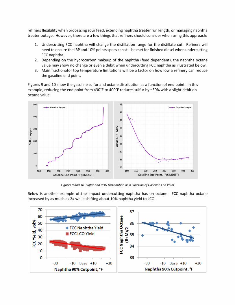
Figures 9 and 10 show the gasoline sulfur and octane distribution as a function of end point. In this example, reducing the end point from 430°F to 400°F reduces sulfur by ~30% with a slight debit on octane value.
Figures 9 and 10. Sulfur and RON Distribution as a Function of Gasoline End Point
Below is another example of the impact undercutting naphtha has on octane. FCC naphtha octane increased by as much as 2# while shifting about 10% naphtha yield to LCO.
450400350300250200150100
500
400
300
200
100
0
Gasoline End Point, °F(SIMDIST)
Sulfu
r, w
ppm
Gasoline Sample
450400350300250200150100
93
92
91
90
89
88
87
86
85
Gasoline End Point, °F(SIMDIST)
Oct
ane,
(R+
M)/
2
Gasoline Sample

Figures 11 and 12. Refinery data, FCC Naphtha Yield and Octane Shift from Undercutting FCC Naphtha
The examples above illustrate that gasoline endpoint can have varying effects on octane. Because of the variability, test runs are recommended to understand the impact of undercutting FCC Naphtha on octane for a given FCC unit, feed, and operation.
When applying a generic price set with a slight preference to LCO over gasoline to the example shown in figures 11 and 12, this shift in operation is economically attractive. For a 50 kbpd FCC unit, the benefit from undercutting naphtha by 10°F for this refinery is estimated to be $6MM/yr (+$0.35/bbl).
Figure 13. Driving Octane by Undercutting FCC Naphtha
Case 3: Catalytic Solutions
In addition to operating changes, modifications can be made to the FCC catalyst itself to drive octane; however, each of these changes will have other impacts on the FCC yield profile and overall unit profitability.
Within traditional FCC technologies, refiners can pursue zeolite modifications to drive octane. Most commonly, a reduced zeolite unit cell size will favor olefin production, which will lead to higher gasoline octanes, as well as higher olefin production for the alkylation unit. However, reduced zeolite unit cell size is typically achieved by reducing zeolite rare earth stabilization, which reduces the acid site density of the zeolite, leading to lower activity per unit of zeolite. Catalyst suppliers can increase zeolite content up to a point, depending on the catalyst family, but beyond this point, the refiner will have to consider alternate catalyst formulations or higher catalyst additions if in‐unit activity is not maintained. Figure 14 shows the relationship between FCC gasoline octane and zeolite unit cell size in traditional FCC catalysts.
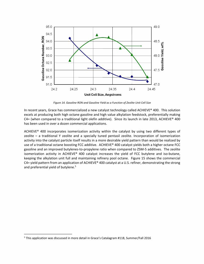
Figure 14. Gasoline RON and Gasoline Yield as a Function of Zeolite Unit Cell Size
In recent years, Grace has commercialized a new catalyst technology called ACHIEVE® 400. This solution excels at producing both high octane gasoline and high value alkylation feedstock, preferentially making C4= (when compared to a traditional light olefin additive). Since its launch in late 2013, ACHIEVE® 400 has been used in over a dozen commercial applications.
ACHIEVE® 400 incorporates isomerization activity within the catalyst by using two different types of zeolite – a traditional Y zeolite and a specially tuned pentasil zeolite. Incorporation of isomerization activity into the catalyst particle itself results in a more desirable yield pattern than would be realized by use of a traditional octane boosting FCC additive. ACHIEVE® 400 catalyst yields both a higher octane FCC gasoline and an improved butylenes‐to‐propylene ratio when compared to ZSM‐5 additives. The zeolite isomerization activity in ACHIEVE® 400 catalyst increases the yield of FCC butylene and iso‐butane, keeping the alkylation unit full and maintaining refinery pool octane. Figure 15 shows the commercial C4= yield pattern from an application of ACHIEVE® 400 catalyst at a U.S. refiner, demonstrating the strong and preferential yield of butylene.5
5 This application was discussed in more detail in Grace’s Catalagram #118, Summer/Fall 2016

Figure 15. Higher C4= Yield with ACHIEVE® 400 Technology at a U.S. Refiner
When applying ACHIEVE® 400 in a typical case, gasoline octane and LPG olefins are driven at the expense of FCC gasoline volume. Figure 16 illustrates the economic value added by using ACHIEVE® 400 to drive octane in a typical 50 kbpd refinery.
Figure 16. Value Derived from Use of ACHIEVE® 400 in a 50 kbpd Refinery

ACHIEVE® 400 technology is part of Grace’s broader ACHIEVE® catalyst technologies, which have been deployed in over 30 commercial applications to date. In commercial operations, product value uplifts in the range of $0.45‐$0.95/bbl have been observed.
Case 4: Additive Solution
In addition to catalytic solutions like the ACHIEVE® 400 catalyst mentioned in Case 3, many refiners have experiences using light olefins (LO) additives as another way to boost LPG olefins as alky feed and increase FCC gasoline octane. Conventional LO additives, generally containing ZSM‐5 zeolite, are designed to increase propylene and butylene yields at the expense of low octane gasoline range molecules. These incremental LPG olefins can be sent to the alkylation unit to produce higher octane alkylate for the refinery gasoline pool. Many of these conventional LO additives tend to be more propylene selective, thus providing an excellent source of propylene if the refinery is integrated with a chemical plant. These additives can also be modified to isomerize low value straight chain olefins in the FCC naphtha into higher octane branched components.
The chart below illustrates the effect of conventional LO additives on LPG olefins yield. The extent of incremental LPG olefins depends on a few different factors such as operating conditions, feedstock, base catalyst, and the additive itself. High activity additive and low hydrogen transfer base catalyst is the recipe to maximize LPG olefins at a constant additive usage. Conversely, low activity additive and high hydrogen transfer base catalyst will reduce the extent of improved LPG yields. The effect of conventional LO additives on gasoline RON is also shown below. As base RON increases, the incremental improvement diminishes; therefore, the starting or base octane must be considered when using LO additives.
Figures 17 & 18. Effect of ZSM‐5 Additive on LPG Olefins and Gasoline RON
In the case study below, incremental LPG olefins and higher gasoline octane were achieved by the addition of conventional LO additive. For a 50 kbpd FCC unit, the benefit from using LO additive is estimated to be $17MM/yr (+$0.93/bbl). It is important to note that the potential for value uplift in any specific refinery is often bound by unit constraints or refinery operations.
0
1
2
3
4
5
6
7
8
9
10
Incremental LPG Olefins, wt%
Additive in Inventory, wt%
OlefinsUltra®, Base Cat ‐ Low Hydrogen Transfer
OlefinsUltra®, Base Cat ‐ High Hydrogen Transfer
Additive B, Base Cat ‐ High Hydrogen Transfer
84
86
88
90
92
94
96
RO
N
Additive in Inventory, wt%
IncreasingBase RON
Base Case Base + ZSM‐5 Additive
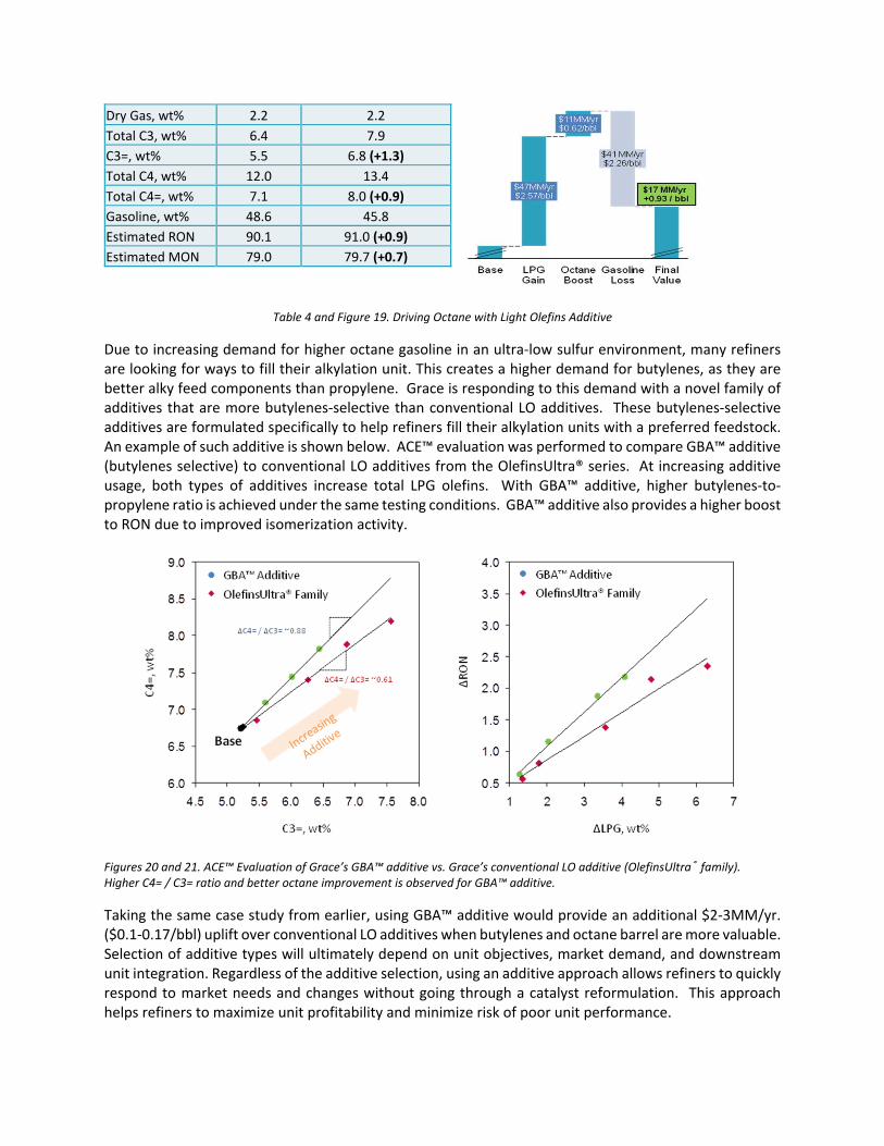
Table 4 and Figure 19. Driving Octane with Light Olefins Additive
Due to increasing demand for higher octane gasoline in an ultra‐low sulfur environment, many refiners are looking for ways to fill their alkylation unit. This creates a higher demand for butylenes, as they are better alky feed components than propylene. Grace is responding to this demand with a novel family of additives that are more butylenes‐selective than conventional LO additives. These butylenes‐selective additives are formulated specifically to help refiners fill their alkylation units with a preferred feedstock. An example of such additive is shown below. ACE™ evaluation was performed to compare GBA™ additive (butylenes selective) to conventional LO additives from the OlefinsUltra® series. At increasing additive usage, both types of additives increase total LPG olefins. With GBA™ additive, higher butylenes‐to‐propylene ratio is achieved under the same testing conditions. GBA™ additive also provides a higher boost to RON due to improved isomerization activity.
Figures 20 and 21. ACE™ Evaluation of Grace’s GBA™ additive vs. Grace’s conventional LO additive (OlefinsUltra® family). Higher C4= / C3= ratio and better octane improvement is observed for GBA™ additive.
Taking the same case study from earlier, using GBA™ additive would provide an additional $2‐3MM/yr. ($0.1‐0.17/bbl) uplift over conventional LO additives when butylenes and octane barrel are more valuable. Selection of additive types will ultimately depend on unit objectives, market demand, and downstream unit integration. Regardless of the additive selection, using an additive approach allows refiners to quickly respond to market needs and changes without going through a catalyst reformulation. This approach helps refiners to maximize unit profitability and minimize risk of poor unit performance.
Dry Gas, wt% 2.2 2.2
Total C3, wt% 6.4 7.9
C3=, wt% 5.5 6.8 (+1.3)
Total C4, wt% 12.0 13.4
Total C4=, wt% 7.1 8.0 (+0.9)
Gasoline, wt% 48.6 45.8
Estimated RON 90.1 91.0 (+0.9)
Estimated MON 79.0 79.7 (+0.7)

Case 5: GSR® Technology
One disadvantage of using a higher severity of gasoline post‐treatment to achieve desulfurization is the subsequent decrease in post‐treated octane. As a result, many refiners around the world, including North America4, have used FCC gasoline sulfur reduction technology as a means of minimizing this negative impact on octane. Furthermore, many refiners in North America are currently evaluating the option to utilize FCC gasoline sulfur reduction technology as part of their overall strategy to comply with Tier 3.
North America is not the first region to face the challenge of achieving 10 ppm gasoline sulfur. Japan was the first country to implement such a national limit. A reduction to 10 ppm gasoline sulfur was made compulsory in January 2008; however, the Japanese petroleum industry moved on a voluntary basis to this level at the beginning of 2005. The size of this challenge was even bigger considering that a maximum of 10 ppm sulfur was imposed, rather than the weighted average of 10 ppm sulfur under the Tier 3 legislation. Grace’s GSR® technology has successfully been used by the majority of refineries in Japan, playing an important part in their strategy for environmental compliance. Nine FCC units in Japan have used GSR® technology on an ongoing basis, with 50% of Japanese refiners currently using such technology.
The chemistry of sulfur reduction in the FCC has been heavily studied and documented in prior works. Sulfur reduction mechanisms and effectiveness vary depending on the technology employed and the feed and unit conditions. Figure 22 shows the general pathway for reduction of thiophenic sulfur species in FCC gasoline.
Figure 22. Reduction Pathway of Thiophenic Sulfur Species to H2S
Further, as part of its product development and research efforts, Grace’s R&D team undertook extensive efforts to analyze the exact mechanisms of sulfur reduction in the FCC. The following reaction mechanism for sulfur removal from the FCC (Figure 23) for Grace’s D‐PriSM® product has been proposed based on that work:

Figure 23. Reaction Mechanism of Sulfur Removal with Grace D‐PriSM® Product
Of importance in this mechanism is that sulfur in thiophenic species is catalytically converted to H2S in the FCC unit, resulting in no incremental formation of regenerator SOx. In all commercial applications, the incremental H2S created is so small that it is within the measurement error for detection in the FCC mass balance.
Figures 24 and 25 show data from two Japanese refining operations.6 In the first graph, D‐PriSM® additive technology reduced sulfur by 25%. In the second application, a 35% reduction in gasoline sulfur was achieved using Grace’s SuRCA® catalyst.
6 These applications, as well as more information on Grace’s GSR® technologies, are discussed in Catalagram # 118, Summer/Fall 2016
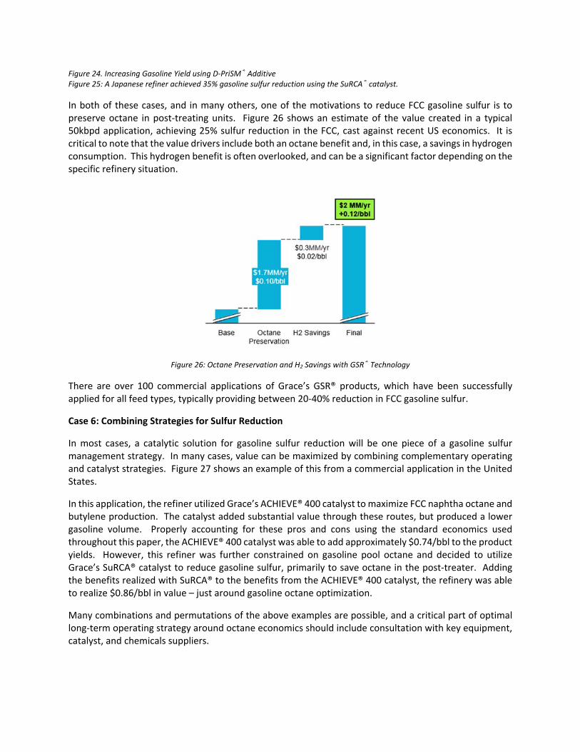
Figure 24. Increasing Gasoline Yield using D‐PriSM® Additive Figure 25: A Japanese refiner achieved 35% gasoline sulfur reduction using the SuRCA® catalyst.
In both of these cases, and in many others, one of the motivations to reduce FCC gasoline sulfur is to preserve octane in post‐treating units. Figure 26 shows an estimate of the value created in a typical 50kbpd application, achieving 25% sulfur reduction in the FCC, cast against recent US economics. It is critical to note that the value drivers include both an octane benefit and, in this case, a savings in hydrogen consumption. This hydrogen benefit is often overlooked, and can be a significant factor depending on the specific refinery situation.
Figure 26: Octane Preservation and H2 Savings with GSR® Technology
There are over 100 commercial applications of Grace’s GSR® products, which have been successfully applied for all feed types, typically providing between 20‐40% reduction in FCC gasoline sulfur.
Case 6: Combining Strategies for Sulfur Reduction
In most cases, a catalytic solution for gasoline sulfur reduction will be one piece of a gasoline sulfur management strategy. In many cases, value can be maximized by combining complementary operating and catalyst strategies. Figure 27 shows an example of this from a commercial application in the United States.
In this application, the refiner utilized Grace’s ACHIEVE® 400 catalyst to maximize FCC naphtha octane and butylene production. The catalyst added substantial value through these routes, but produced a lower gasoline volume. Properly accounting for these pros and cons using the standard economics used throughout this paper, the ACHIEVE® 400 catalyst was able to add approximately $0.74/bbl to the product yields. However, this refiner was further constrained on gasoline pool octane and decided to utilize Grace’s SuRCA® catalyst to reduce gasoline sulfur, primarily to save octane in the post‐treater. Adding the benefits realized with SuRCA® to the benefits from the ACHIEVE® 400 catalyst, the refinery was able to realize $0.86/bbl in value – just around gasoline octane optimization.
Many combinations and permutations of the above examples are possible, and a critical part of optimal long‐term operating strategy around octane economics should include consultation with key equipment, catalyst, and chemicals suppliers.

Figure 27: Combining Different Strategies to Maximize Octane in an Ultra‐low Sulfur Gasoline Market
SUMMARY
Tier 3 gasoline regulations, as well as other low sulfur gasoline regulations around the world, will put increasing pressure on refiners to maintain octane pool levels while meeting ever lower levels of sulfur content in refinery gasoline. Refiners have a variety of options to manage pool sulfur, depending on their configuration and local markets. Operating strategies include selection of FCC cut points and reactor temperature. Feedstock selection can also play an important role in octane production; shale and other paraffinic feedstocks can be detractors to octane, and naphthenic and aromatic feedstocks can be contributors. Catalysts and additives specifically designed to either produce higher octanes, higher LPG olefins (especially C4=), or both, can add significant value to refiners’ operations. Finally, catalytic gasoline sulfur reduction can play a role in minimizing octane loss in gasoline post‐treaters. Many refiners will consider and ultimately employ several of these strategies in parallel to maximize refinery octane.
i http://www.eia.gov/todayinenergy/detail.php?id=25692 ii http://www.nhtsa.gov/staticfiles/rulemaking/pdf/cafe/Performance‐summary‐report‐12152014‐v2.pdf iii https://www.transportation.gov/mission/sustainability/corporate‐average‐fuel‐economy‐cafe‐standards https://www.nhtsa.gov/staticfiles/rulemaking/pdf/cafe/Draft‐TAR‐Final.pdf iv http://www.eia.gov/todayinenergy/detail.php?id=25692