pennsylvania transmittal letter pub 464 - dot.state.pa.us 464.pdf · pennsylvania transmittal...
TRANSCRIPT

OS-299 (7-08) PUBLICATION:
pennsylvania TRANSMITTAL LETTER Pub 464 DEPARTMENT OF TRANSPORTATION
www.dot.state.pa.us
SUBJECT:
DATE:
Au ust 12 2013
PUBLICATION 464 - MAINTENANCE FIELD REFERENCE FOR EROSION AND SEDIMENTATION CONTROL
2013 EDITION (2ND Printing)
INFORMATION AND SPECIAL INSTRUCTIONS:
2013 Edition (2"d Printing) August Updated Printing. To be used as a guide during maintenance activities involving earth disturbance.
CANCEL AND DESTROY THE FOLLOWING:
OCTOBER 15, 2003 EDITION
ADDITIONAL COPIES ARE AVAILABLE FROM:
D PennDOT SALES STORE (717) 787-6746 phone (717} 787-8779 fax [email protected]
D PennDOT website- www.dot.state.pa.us Click on Forms, Publications & Maps
[81 DGS warehouse (PennDOT employees ONLY}
A�VED FOR I SU'A��""--_;
Brian Thompson, P.E. ACTING DIRECTOR, Bureau of Maintenance and Operations

PENNSYLVANIA DEPARTMENT OF
TRANSPORTATION
Bureau of Maintenance and Operations
Publication No. 464
MAINTENANCE FIELD REFERENCE FOR EROSION AND SEDIMENT CONTROLS
PUB 464 (8-13)

PENNDOT Maintenance Field Reference for Erosion and Sediment Controls
PREFACE This field reference is for use as a guidance document by highway maintenance staff to help them meet the requirements of Federal and State laws and their regulations related to Erosion and Sediment (E&S) Pollution Control Measures. The circumstances of each potential situation involving erosion and sediment pollution control may vary, and therefore, should be evaluated on a case by case basis.
The procedures herein are not an adjudication or regulation. There is no intent on the part of PENNDOT to give the procedures in this field reference weight or deference. This document establishes the guidance within which PENNDOT will implement a fixed range of its erosion and sediment pollution control Best Management Practices (BMPs). PENNDOT reserves the right to deviate from this field reference if circumstances warrant the use of alternative BMPs to comply with state regulations, or if necessary to control or prevent E&S pollution. This field reference is for informational purposes only; it is not regulatory.
This manual is designed as a guide to Erosion and Sediment Controls to be used during Maintenance Activities. If you are unsure if a permit is required for the work being performed, please contact your supervisor, environmental representative or the local Conservation District for guidance. The two permitting programs that may be applicable to maintenance projects are the NPDES and Chapter 105 permitting programs. The Chapter 102 regulations (25 Pa. Code Chapter 102) set forth the requirements for erosion and sedimentation controls and the NPDES program for stormwater discharges associated with construction activities. Generally, a National Pollutant Discharge Elimination System (NPDES) Permit from DEP is not required for activities that qualify as “road maintenance activities” under the regulations if the area of disturbance is under 25 acres. However, the regulations still require the use of erosion and sedimentation control best management practices for road maintenance activities. For additional guidance on the Chapter 102 (NPDES) requirements for road maintenance activities, please refer to Chapter 12, Appendix E of the Drainage Manual (Publication 584). A Chapter 105 permit is required for any location where encroachment to wetlands or modifications to Waters of the Commonwealth may occur. Guidelines for permit requirements for in channel work can be found at the beginning of the In channel (IC) section of the manual.
i

MAINTENANCE ACTIVITY/BMP TABLE
KEY: x - Indicates that use of the BMP marked should be considered, dependent on site conditions, and used when appropriate, when performing the corresponding activity. Blank indicates that use of the BMP with the corresponding activity is unlikely.
BMP → ST
.1.SE
ED
S
eeding
ST
.2.TP
SL
T
opsoil
ST
.3.ML
CH
M
ulching
ST
.4.HA
BK
H
ydraulically Applied B
lankets
ST
.5.RO
CK
R
ock Stabilization
ST
.6.EC
B
Erosion C
ontrol Blanket (E
CB
)
ST
.7.TR
M
Turf R
einforcement M
at (TR
M)
ST
.8.PR
EP
S
urface Preparation
ST
.9.GE
OT
G
eotextile Lining
ST
.10.RO
LL
R
olling
ST
.11.GA
BI
Gabions
ES
.1.ST
RW
S
traw B
ale Barriers
ES
.2.SIL
T
Silt B
arrier Fence
ES
.3.SS
F
Super S
ilt Fence
ES
.4.RF
OT
R
ock Filter O
utlet
ES
.5.INL
T
Storm
Inlet Protection
ES
.6.VE
GF
V
egetative Filter S
trip
Maintenance Activity ↓ 7112-Unpaved Roads Shaping X X
7113-Unpaved Roads- Re-stabilization
X X
7136-Pavement Widening X X X X X X X X
X
X
X
X
X
7121-Patching X
X
7212-Shoulder Grading X X X
X
7213-Shoulder Stabilization X X X X X X
X
7215-Shoulder Cutting1 X X X X X X
X
X
X
X
X
X
7216-Shoulder Upgrading X
X
7221-Shoulder Patching X
X
7311-Inlet/Endwall Cleaning X X X X X
7312-Reshaping/Ditch Cleaning
X X X X X X X X X
X
7314-Pipe Cleaning
X 7321-Inlets
X X X X X
7324-Pipe Installation X X X X X X
X
7331-Side Dozing X X X X X
7332-Roadway Sect. Restor. & Slope Stab.
X X X X X X X X X
X
X
X
7341-Emergency Damage X X X X X X X X X X X
X
X
X
X
X
X
7431-Bridge Cleaning
X
X
1Work beyond the edge of the shoulder is to be handled under Maintenance Activity 7312.

MAINTENANCE ACTIVITY/BMP TABLE
KEY: x - Indicates that use of the BMP marked should be considered, dependent on site conditions, and used when appropriate, when performing the corresponding activity. Blank indicates that use of the BMP with the corresponding activity is unlikely.
ES
.7.BE
RM
T
op of Slope B
erm
ES
.8.PIP
E
Tem
porary Slope P
ipe
ES
.9.OU
TL
O
utlet Protection
ES
.10.BE
NC
B
enches
ES
.11.LIN
G
Channel L
inings
ES
.12.RF
IL
Rock F
ilter
ES
.13.FB
AG
P
umped W
ater Filter B
ag
ES
.14.RC
E
Rock C
onstruction Entrance
ES
.15.CF
S
Com
post Filter S
ock
ES
.16.CF
B
Com
post Filter B
erm
ES
.17.ST
B
Sedim
ent Traps and B
asins
ES
.18.CS
ST
C
ompost S
ock Sedim
ent Trap
ES
.19.CW
SH
C
oncrete Washout
IC.1.B
YP
S
Bypass C
hannel with N
on-Erosive L
ining
IC.2.F
LM
E
Tem
porary Stream
Diversion: F
lume
Through W
ork Area
IC.3.P
UM
P
Tem
porary Stream
Diversion: P
ump
Around In-C
hannel Work A
rea
IC.4.C
OF
F
In-Stream
Cofferdam
Diversion
← BMP
Maintenance Activity
↓
7112-Unpaved Road Shaping
7113-Unpaved Roads
Re-stabilization
X
7121-Patching
X
X
7136-Pavement Widening
7212-ShoulderGrading
7213-ShoulderStabilization
X
7215-Shoulder/ Cutting
X
X
7216-Shoulder Upgrading
7221-Shoulder Patching
X
7311-Inlet/Endwall
Cleaning
X X X X 7312-
Reshaping/DitchCleaning
X
7314-Pipe Cleaning
X 7321-Inlets
X X X X
X
X
X
X
7324-Pipe Installation
X
X X
7331-Side Dozing
X
X X X
7332-Roadway Sect.
Restor. & Slope Stab.
X X X X X X X X X X X X
X
X
X
X
X
7341-EmergencyDamage
X
X
7431-Bridge Cleaning

PENNDOT Maintenance Field Reference for Erosion and Sediment Controls
Page INTRODUCTION AND GENERAL INFORMATION……1
STABILIZATION METHODS AND STANDARDS ST.1.SEED Seeding………………………………………... 8 ST.2.TPSL Topsoil……………………………………….. 13 ST.3.MLCH Mulching……………………………………… 14 ST.4.HABK Hydraulically Applied Blankets……………... 16 ST.5.ROCK Rock Stabilization……………………………. 17 ST.6.ECB Erosion Control Blanket (ECB)………………. 18 ST.7.TRM Turf Reinforcement Mat (TRM)………………. 24 ST.8.PREP Surface Preparation…………………………... 26 ST.9.GEOT Geotextile Lining……………………………. 29 ST.10.ROLL Rolling………………………………………. 32 ST.11.GABI Gabions……………………………………… 33
COMMON EROSION AND SEDIMENT CONTROLS ES.1.STRW Straw Bale Barriers…………………………. 36 ES.2.SILT Silt Barrier Fence…………………………… 40 ES.3.SSF Super Silt Fence…………………………….. 45 ES.4.RFOT Rock Filter Outlet…………………………….. 48 ES.5.INLT Storm Inlet Protection………………………. 50 ES.6.VEGF Vegetative Filter Strip………………………. 56 ES.7.BERM Top of Slope Berm………………………….. 58 ES.8.PIPE Temporary Slope Pipe………………………. 62 ES.9.OUTL Outlet Protection……………………………. 65 ES.10.BENC Benches……………………………………… 73 ES.11.LING Channel Linings……………………………... 75 ES.12.RFIL Rock Filter…………………………………. 80 ES.13.FBAG Pumped Water Filter Bag……………………. 82 ES.14.RCE Rock Construction Entrance………………………. 85 ES.15.CFS Compost Filter Sock……………………………… 87 ES.16.CFB Compost Filter Berm………………………… 89 ES.17.STB Sediment Traps and Basins………………….. 91 ES.18.CSST Compost Sock Sediment Trap………………. 95 ES.19.CWSH Concrete Washout…………………………… 97
iv

EROSION AND SEDIMENT CONTROLS FOR IN-CHANNEL WORK
IC.1.BYPS Bypass Channel with Non-Erosive Lining………. 99 IC.2.FLME Temporary Stream Diversion: Flume
Through Work Area……………………………… 101 IC.3.PUMP Temporary Stream Diversion: Pump
Around In-Channel Work Area………………….. 103 IC.4.COFF In-Stream Cofferdam Diversion………………… 105
APPENDICES A. ROCK SIZE TABLES…………………………………... 108
B. CONTACT INFORMATION………………………… 110
TABLES Number Heading Page 1 Seeding Formula Descriptions and Rates………. 9 2 Seeding Dates………………………………….... 10 3 Soil Supplement Rates………………………….. 12 4 Cubic Yards of Topsoil Required for Application. 13 5 Mulching Application Rates…………………… 15 6 Application Rates for Mulch Binders………….. 15 7 Fabric Placement……………………………….. 30 8 Securing Pin Spacing…………………………… 30 9 Maximum Slope Length for Straw Bale Barriers. 38 10 Maximum Up-Slope Length……………………. 40 11 Silt Barrier Fence Geotextile Selection…………. 42 12 Maximum Slope Length for Super Silt Fence….. 45 13 Minimum Width for Vegetative Filter Strips……. 56 14 Berm Dimensions………………………………... 59 15 Stabilization Methods for Top of Slope Berms….. 59 16 Suggested Minimum Sizes for Temporary
Slope Pipes……………………………………... 63 17 Bench Spacing………………………………….. 73 18 Maximum Allowable Velocities for
Channels Lined with Vegetative Cover………… 78 19 Rock Size (See Appendix A)…………………… 81 20 Slope to Slope Relationships for Compost Filter Sock………………………………………. 88
v

FIGURES Number Description Page 1 Blanket/Mat Orientation……………………….. 20 2 Anchor Trench…………………………………. 21 3 Check Slot……………………………………… 21 4 Anchor Patterns………………………………… 22 5 TRM and Soil Contact…………………………. 24 6 Tracking a Fill Slope…………………………… 27 7 Stair-Step Grading……………………………… 27 8 Grooving Slopes……………………………...... 28 9 Gabion Channel Deflector……………………… 34
10 Gabion…………..……………………………… 34 11 Straw Bale Barrier…………………………....... 37 12 Straw Bale Barrier Staking……………………. 37 13 Straw Bale Barrier Placement……..…………... 37 14 Straw Barrier Contour Plan.…………………… 38 15 Standard Silt Barrier Fence 18-Inch High…….. 41 16 Silt Barrier Fence Detail A…………………..... 41 17 Silt Barrier Fence……………………………… 42 18 Silt Barrier Fence Joining Details…………….. 42 19 Reinforced Silt Barrier Fence -
30 Inch High……………………………… 43 20 Super Silt Fence………….…………………… 46 21 Geotextile Overlap Detail…………..………… 47 22 Rock Filter Outlet …………………….…..….. 48 23 Storm Inlet Protection………………………… 51 24 Storm Inlet Protection for Type C, Type S or
Type M Inlet Protection Side View…… 51 25 Inlet Filter Bag Protection ……...……………. 52 26 Inlet Filter Bag Protection for Type M or
Type S Inlet …………………….……….. 53 27 Concrete Block/Gravel Inlet Protection for
Type C………………………………………. 54 28 Top of Slope Berm……………………………… 58 29 Top of Slope Berm-Section A View……………. 59 30 Temporary Slope Pipe………………………….. 62
vi
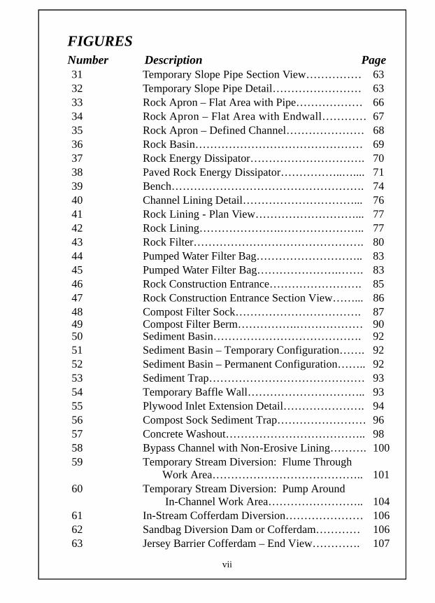
FIGURES Number Description Page 31 Temporary Slope Pipe Section View…………… 63 32 Temporary Slope Pipe Detail…………………… 63 33 Rock Apron – Flat Area with Pipe……………… 66 34 Rock Apron – Flat Area with Endwall………… 67 35 Rock Apron – Defined Channel………………… 68 36 Rock Basin……………………………………… 69 37 Rock Energy Dissipator…………………………. 70 38 Paved Rock Energy Dissipator……………..….... 71 39 Bench……………………………………………. 74 40 Channel Lining Detail…………………………... 76 41 Rock Lining - Plan View………………………... 77 42 Rock Lining………………….………………….. 77 43 Rock Filter………………………………………. 80 44 Pumped Water Filter Bag……………………….. 83 45 Pumped Water Filter Bag………………….……. 83 46 Rock Construction Entrance……………………. 85 47 Rock Construction Entrance Section View……... 86 48 Compost Filter Sock……………………………. 87 49 Compost Filter Berm…………….……………… 90 50 Sediment Basin…………………………………. 92 51 Sediment Basin – Temporary Configuration……. 92 52 Sediment Basin – Permanent Configuration…….. 92 53 Sediment Trap…………………………………… 93 54 Temporary Baffle Wall………………………….. 93 55 Plywood Inlet Extension Detail…………………. 94 56 Compost Sock Sediment Trap…………………… 96 57 Concrete Washout……………………………….. 98 58 Bypass Channel with Non-Erosive Lining………. 100 59 Temporary Stream Diversion: Flume Through Work Area………………………………….. 101 60 Temporary Stream Diversion: Pump Around In-Channel Work Area…………………….. 104 61 In-Stream Cofferdam Diversion………………… 106 62 Sandbag Diversion Dam or Cofferdam………… 106 63 Jersey Barrier Cofferdam – End View…………. 107
vii

1
PENNDOT Maintenance Field Reference for Erosion and Sediment Controls
The purpose of this field guide is to provide a field-ready source of information commonly needed by roadway maintenance personnel for the installation, inspection, and maintenance of Erosion and Sediment Control Best Management Practices (BMPs). Guidance for the design of BMPs more complex than contained in this guide can be found in other PENNDOT design documents. These BMPs are designed for consistency with the Department of Environmental Protection (DEP) Erosion and Sediment Pollution Control Program Manual and to meet the special requirements of the highway environment. Soil Erosion and Sediment Control is based on nine basic principles, which include: 1) Minimizing the amount of disturbance. 2) Avoiding sensitive areas. 3) Sequencing, grading, and inspecting to ensure that during work,
each E&S BMP is receiving the drainage intended for that BMP. 4) Minimizing the time of disturbance and stabilizing disturbed areas
immediately. 5) Collecting and removing sediments within the project site to prevent
them from entering waters of the Commonwealth. 6) Controlling runoff onto, through, and from the project site to avoid
accelerated erosion. 7) Diverting offsite runoff around the disturbed areas, when beneficial. 8) Ensuring that disturbed areas are stabilized and protected by onsite
and perimeter E&S BMPs at the end of each work day. 9) Ensuring proper installation and operation of BMPs by performing
routine inspections and maintenance of the project site and especially the E&S control measures.
2
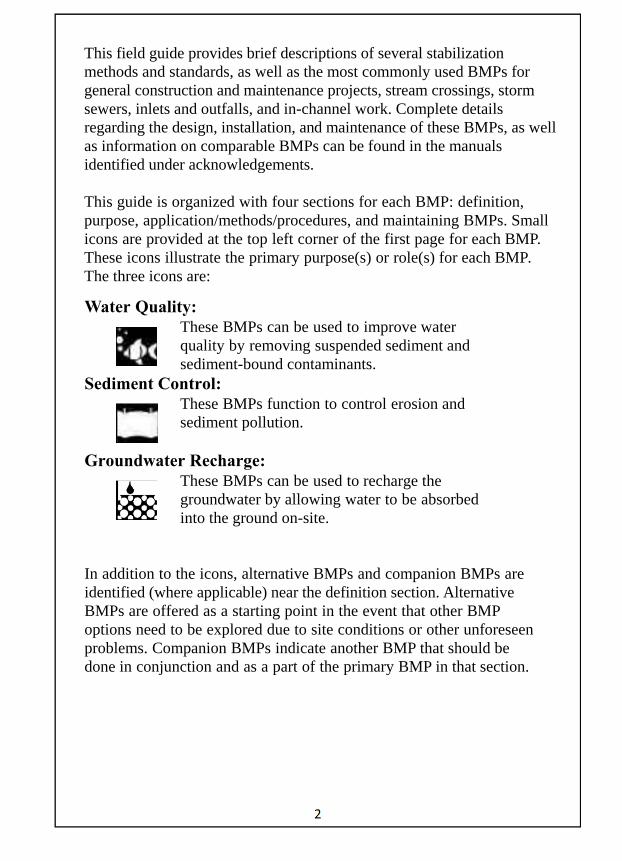
This field guide provides brief descriptions of several stabilization methods and standards, as well as the most commonly used BMPs for general construction and maintenance projects, stream crossings, storm sewers, inlets and outfalls, and in-channel work. Complete details regarding the design, installation, and maintenance of these BMPs, as well as information on comparable BMPs can be found in the manuals identified under acknowledgements. This guide is organized with four sections for each BMP: definition, purpose, application/methods/procedures, and maintaining BMPs. Small icons are provided at the top left corner of the first page for each BMP. These icons illustrate the primary purpose(s) or role(s) for each BMP. The three icons are:
Water Quality: These BMPs can be used to improve water quality by removing suspended sediment and sediment-bound contaminants.
Sediment Control: These BMPs function to control erosion and sediment pollution.
Groundwater Recharge:
These BMPs can be used to recharge the groundwater by allowing water to be absorbed into the ground on-site.
In addition to the icons, alternative BMPs and companion BMPs are identified (where applicable) near the definition section. Alternative BMPs are offered as a starting point in the event that other BMP options need to be explored due to site conditions or other unforeseen problems. Companion BMPs indicate another BMP that should be done in conjunction and as a part of the primary BMP in that section.
3
For Example: Companion BMPs to the IC.2.FLME are ES.4.RFOT and ES.12.FBAG. A Temporary Stream Diversion: Flume Through Work Area is never done without using a Rock Filter Outlet and pumped water filter bag. However, the relationship between the primary BMPs and companion BMPs are not always interchangeable. For Example: The IC.2.FLME is not a companion BMP to the ES.4.RFOT or the ES.12.FBAG. Both Rock Filter Outlets and pumped water filter bags can be used without a Temporary Stream Diversion: Flume Through Work Area.
SPECIAL PROTECTION WATERSHEDS: Special attention should be paid to identify the locations of High Quality and Exceptional Value (HQ/EV) Watersheds. If work is to be done in areas designated as High Quality and Exceptional Value (HQ/EV) Watersheds, there may be different requirements for E&S control. Contact the County Maintenance Manager for guidance regarding current locations and requirements for E&S BMPs in High Quality and Exceptional Value (HQ/EV) Watersheds.
APPLICABILITY OF GUIDE:
1) This guide may be used for common daily maintenance operations that require E&S measures but do not require project-specific construction plans.
2) Construction plans take precedence over this guide. 3) Approved E&S plans take precedence over this guide.
DEFINITIONS: ACCELERATED EROSION - The removal of the surface of the land through the combined action of human activities and the natural processes, at a rate greater than would occur because of the natural process alone. (25 PA Code 102.1) BEST MANAGEMENT PRACTICE (BMP)- Activities, facilities, measures, planning or procedures used to minimize accelerated erosion and sedimentation and manage stormwater to protect, maintain, reclaim, and restore the quality of waters and the existing and designated uses of waters within this Commonwealth before, during, and after earth disturbance activities. (25 PA Code 102.1)

4
IMMEDIATELY - as soon as personnel can reasonably perform the work during normal working hours. PERMANENT MATERIALS- Non-biodegradable materials placed for long-term protection. PERMANENT STABILIZATION-A minimum, uniform 70% perennial vegetative cover and density, or 100% non-vegetative cover which will resist accelerated erosion or the proper placing of other materials to avoid sliding or other movement.
ROAD MAINTENANCE ACTIVITIES -
(i) Earth disturbance activities within the existing road cross-section or railroad right-of-way including the following:
(A) Shaping or restabilizing unpaved roads.
(B) Shoulder grading.
(C) Slope stabilization.
(D) Cutting of existing cut slopes.
(E) Inlet and endwall cleaning.
(F) Reshaping and cleaning drainage ditches and swales.
(G) Pipe cleaning.
(H) Pipe replacement.
(I) Support activities incidental to resurfacing activities such as minor vertical adjustment to meet grade of resurfaced area.
(J) Ballast cleaning.
(K) Laying additional ballast.
(L) Replacing ballast, ties and rails.
(M) Other similar activities.
5
(ii) The existing road cross-section consists of the original graded area between the existing toes of fill slopes and tops of cut slopes on either side of the road and any associated drainage features. ROCK- Rock stabilization for accelerated erosion control. STABILIZE- The use of a BMP method to control accelerated erosion and, if in a disturbed area, to prevent sediment pollution from leaving the disturbed area or the proper placing of other materials to avoid sliding or other movement. TEMPORARY MATERIALS –Materials that are biodegradable or are to be removed after the area has been permanently stabilized. TEMPORARY STABILIZATION- Provides immediate control of accelerated erosion from a disturbed area pending further disturbance or stabilization between seeding and establishment of permanent vegetative cover. In this field reference, the principal temporary stabilization measures are mulch, erosion control blankets, and temporary vegetative cover. WATERS OF THE COMMONWEALTH- Rivers, streams, creeks, rivulets, impoundments, ditches, watercourses, storm sewers, lakes, dammed water, wetlands, ponds, springs, and other bodies or channels of conveyance of surface and underground water, or parts thereof, whether natural or artificial. ABBREVIATIONS:
BMP – Best Management Practice
CCD – County Conservation District
DEP – Department of Environmental Protection
ECB – Erosion Control Blanket
E&S – Erosion and Sediment Pollution Control
PCSM – Post Construction Stormwater Management
PENNDOT – Pennsylvania Department of Transportation
PLS – Pure Live Seed

6
ABBREVIATIONS CONTINUED:
ROW – Right-of-Way
TRM – Turf Reinforcement Mat
in – inches
ft – feet
yd – yards
mi – miles
fl oz – fluid ounces
gal – gallons
ft3 – cubic feet
yd3 – cubic yards
in2 – square inches
ft2 – square feet
SY – square yards
ac – acres
ton – ton
lbs – pounds
ft/s – feet per second
ACKNOWLEDGMENTS: The following list identifies resources that were used to compile information for this field guide. Material was taken directly from references 1, 3 and 5.
1. Commonwealth of Pennsylvania, Department of Environmental Protection, Erosion and Sediment Pollution Control Program Manual, March 2012.
7
2. Commonwealth of Pennsylvania, Department of Environmental Protection, Pennsylvania Stormwater Best Management Practices Manual, December 2006.
3. Pennsylvania Department of Transportation, Design Manual-Part
2, Chapter 13, August 2009. 4. Pennsylvania Department of Transportation, Drainage Design
Manual, Publication 584, Chapter 12, 2010 Edition. 5. Pennsylvania Department of Transportation, Maintenance Manual,
Publication 23, June, 2010 Edition. 6. Pennsylvania Department of Transportation, Specifications
Publication 408, Change No. 3, October 5, 2012. 7. Pennsylvania Department of Transportation, Standards for
Roadway Construction, Publications 43M, 70M, 71M, 72M, and 73M, June 2010.

STABILIZATION METHODS AND STANDARDS
8
SEEDING ST.1.SEED
Alternative BMPs: ST.5.ROCK Companion BMPs: ST.8.PREP, ST.2.TPSL and one of the following - ST.3.MLCH, ST.4.HABK, ST.6.ECB or ST.7.TRM
DEFINITION: The establishment of a vegetative cover, permanent or temporary, on disturbed areas using rapidly growing plants.
PURPOSE: Seeding with various grass or grass and leguminous plant mixtures are necessary to restore vegetative cover to soil surfaces exposed during excavation operations. Restoring the vegetative cover with deep-rooted, long lived and persistent adapted plant species is the most effective measure to prevent extensive soil erosion and any accompanying sediment loss and deposit in undesired areas. The use of permanent seeding or mulching should be anticipated during all earthwork operations.
APPLICATIONS, METHODS, AND PROCEDURES: ● Permanent seeding and mulching shall be placed when project
areas are constructed to finish grade. ● Cessation of activity for at least 4 days requires temporary
stabilization. ● Mulch or ECB should always be applied after seed has been
applied. Apply in accordance with applicable BMP sections. ● In situations where there is not opportunity for seed to germinate
and establish, use mulch or ECBs for temporary stabilization. ● Sow seeds uniformly (according to rates in Table 1) on the prepared
areas by hydraulic placement, broadcasting, drilling, or hand seeding methods. Inspect seeding equipment and adjust if required to assure the specified application rates. Periodically perform a check on the rate and uniformity of application.
● Table 1 describes typical uses for seeding formulas.

9
Seeding Formula
Description
Seeding Rate - lbs per1000 SY
Formula B A refined lawn type generally used on non-steep surfaces where a more highly maintained and mowed surface is desired. Use only on areas which have topsoil.
42.0
Formula C Generally used on slopes steeper than 3H:1V where mowing is not anticipated or desired. Topsoil application is not necessary, do not use within 20 feet or areas where evergreen trees, shrubs, seedlings, or vines are to be planted. Crownvetch will hinder the invasion of adjacent native vegetation for many years.
12.0
Formula D
Generally used on most highway slope areas not receiving Formula C where mowing may or may not be designated. Normally used in drainage channels or swales requiring permanent seeding.
50.0
Formula E Generally used to quickly stabilize exposed soil surfaces because it generally germinates within 2 weeks in favorable climate conditions. Considered most often for temporary use on unfinished graded areas during construction since the life cycle averages 1-2 years.
10.0
Formula L
Can be used on low maintenance slope areas which are not mowed and on flatter areas that are mowed 2 times per year or less. Should not be mowed to a height less than 6 inches. Not very adaptive to wet soil conditions.
48.0
Formula N Can be used as a native grass mixture.
30.0
Formula W Can be used on a wide assortment of conditions from fairly dry to fairly wet soils where non -mow conditions are desired, such as wetland replacement areas or wildlife habitat areas.
15.0
Table 1: Seeding Formula Descriptions and Rates

10
● When seed (generally formulas B, D, and L) is applied to areas that will be mowed (slopes 3H:1V or flatter) topsoil should be used. Refer to PENNDOT Publication 408 Sections 801, 802, and 803 for general installation guidelines.
● Spread seed within the dates listed in Table 2. If conditions warrant, the dates may be extended. If extended, either apply full treatment or apply 50% of permanent seeding and soil supplements and apply the remaining 50% within the next seeding dates.
Table 2: Seeding Dates
● Formula B, C, D, L, N and W require soil supplement applications prior to seed application (see Soil Supplements section below and Table 3). Formula E does not require supplements.
● After seeding, roll topsoiled areas that are to be mowed. Use a roller, having a weight not more than 65 pounds per foot. If soil is wet or frozen, roll only when directed.
● Inoculate leguminous seed with proper cultures in accordance with manufacturer's directions. Prior to sowing, protect inoculated seed from prolonged exposure to sunlight. Seed not sown within 24 hours should be reinoculated. When seed is applied by hydraulic seeders, utilize 4 times the manufacturer's recommended rate for inoculation.
● In critical areas such as those adjacent to or within 50 feet of streams, ponds, or wetlands, use a protective blanket for seeded areas. Seeded areas on slopes steeper than 3H:1V shall be covered with an ECB or suitable alternative.
Seeding Formulas Dates
Formula B, D, L March 15 to June 1 August 1 to October 15
Formula C – Ryegrass March 1 to October 15
Formula C – Crownvetch Anytime except September and October
Formula E, N March 15 to October 15
Formula W April 1 to June 15 August 16 to September 15

11
● Prior to project completion, apply slow-release, nitrogen fertilizer to the surface of Formula B, D, L, N and W areas. Do not apply for Formula C areas.
● On topsoiled areas, where temporary seeding or mulching has been applied, use tillage and soil supplements prior to permanent seeding.
● On untopsoiled areas, where temporary seeding or mulching has been applied, permanent seed and/or soil supplements may be applied without tilling.
● Vegetated areas are considered permanently stabilized when a uniform 70% perennial vegetative cover has been achieved, or the disturbed area is covered with an acceptable BMP which permanently minimizes accelerated erosion and sediment.
● When seeded areas require mulching with hay, straw or other materials such as wood fibers or bonded fiber matrixes, the mulch is integral to the seeding operations.
Tillage ● On topsoiled areas, 3H:1V and flatter, thoroughly loosen the
surface to a depth of at least 2 inches by disking, harrowing, or other acceptable methods until the tillage is satisfactory.
● On untopsoiled areas, 3H:1V and flatter, till only as directed and till or scarify areas when the surface is glazed or crusted.
● Correct surface irregularities by filling any depressions and leveling rough or uneven areas. Remove all metal objects, stones larger than 2 inches, and other debris/objects deemed detrimental to maintenance operations.
Soil Supplements ● Apply supplements as described in Table 3, unless
otherwise indicated by soil sample. ● Uniformly apply lime and commercial fertilizer supplements
to the areas to be seeded, except areas to be seeded with Formula E.
● On topsoiled areas, blend the initial supplements into the soil at least 2 inches by raking, disking, harrowing, or other acceptable methods. This may be done during tillage.

12
Table 3: Soil Supplement Rates MAINTAINING BMPs:
● Maintenance and inspection of the BMP must be continued until the site is permanently stabilized.
● Perform all preventive and remedial maintenance work, including clean-out, repair, replacement, regrading, reseeding, remulching, and renetting immediately following inspection.
● If the BMP fails to perform as expected, the situation must be addressed immediately with replacement BMPs or modifications of those installed.
● Take measures to control prohibited and noxious weeds and other undesired plants by using herbicide, spraying and cutting. Mow as specified.
Supplements Rates
Pulverized Agricultural Limestone 800 lbs per 1,000 SY
10-20-20 Analysis Commercial Fertilizer 140 lbs per 1,000 SY
38-0-0 Ureaform Fertilizer 50 lbs per 1,000 SY
32-0-0 to 38-0-0 Sulfur Coated Urea Fertilizer 59 to 50 lbs per 1,000 SY
31-0-0 IBDU Fertilizer 61 lbs per 1,000 SY

13
Alternative BMPs: None Companion BMPs: ST.1.SEED, ST.3.MLCH, ST.4.HABK, ST.6.ECB, ST.7.TRM
DEFINITION: The addition of topsoil to a surface to improve the establishment of vegetative cover.
PURPOSE: To improve quality of the surface before seeding is placed to ensure uniform vegetative cover.
APPLICATION, METHODS, AND PROCEDURES: ● Graded areas should be scarified or otherwise loosened to a depth of
3 to 5 inches to permit bonding of the topsoil to the surface areas and to provide a roughened surface to prevent topsoil from sliding down slope.
● Topsoil should be uniformly distributed across the disturbed area to a depth of 4 to 8 inches minimum – 2 inches on fill outslopes. Spreading should be done in such a manner that sodding or seeding can proceed with a minimum of additional preparation or tillage. Irregularities in the surface resulting from topsoil placement should be corrected in order to prevent formation of depressions unless such depressions are part of the PCSM plan.
● Topsoil should not be placed while the topsoil or subsoil is in a frozen or muddy condition, when the subsoil is excessively wet, or in a condition that may otherwise be detrimental to proper grading and seedbed preparation. Compacted soils should be scarified 6 to 12 inches along contour whenever possible prior to seeding.
Depth (in) Per 1,000 Square Feet Per Acre 1 3.1 134 2 6.2 268 3 9.3 403 4 12.4 537 5 15.5 672 6 18.6 806 7 21.7 940 8 24.8 1,074
Table 4: Cubic Yards of Topsoil Required for Application
TOPSOIL ST.2.TPSL

14
Alternative BMPs: ST.4.HABK, ST.5.ROCK, ST.6.ECB, ST.7.TRM Companion BMPs: ST.8.PREP and ST.2.TPSL
DEFINITION: Temporary cover of various organic and non-organic materials used to control erosion and sediment, or used during seeding for stabilization and to propagate initial seed growth.
PURPOSE: Absorb rainfall impact, increase the rate of infiltration, reduce soil moisture loss due to evaporation, moderate soil temperatures, provide a suitable environment for seed germination, and protect the seedling from intense sunlight.
APPLICATION, METHODS, AND PROCEDURES: ● Mulch may be used as temporary stabilization of unseeded
disturbed areas or over seeded areas. Mulch temporarily seeded areas with hay.
● Mulch or ECBs should always be placed over seeded areas. ● Straw and hay mulch should be anchored or tackified immediately
after application to prevent being windblown. ● In areas where slope is steeper than 3H:1V use ECBs and not
mulch. ● Place mulch immediately after seeding or within 48 hours after seeding is completed. ● Shredded paper hydromulch should not be used on slopes steeper
than 5%. Wood fiber hydromulch may be applied on steeper slopes provided a tackfier is used. The application for any hydromulch should be 2,000 lb/acre at a minimum.
● See Table 5 for mulches that can be used alone as temporary stabilization in areas where there is no opportunity for seed to germinate and establish. Compost material may also be considered as approved and specified by DEP.
● Apply mulches at the rates shown in Table 5.
MULCHING ST.3.MLCH

15
Mulch Type
Application Rate (Min.)
Notes Suitable for Use as
Temporary Stabilization lbs Per
1,000 SY
Straw 1,200 Either wheat or oat straw, free of weeds, not chopped or finely broken.
No
Hay 1,200 Timothy, mixed clover and timothy, or other native forage grasses.
Yes
Woodchips 185 – 275
lb 1650 – 2500 lb May prevent germination
of grasses & legumes
Hydromulch 47 lb 415 lb
See limitations above
Table 5: Mulch Application Rates
● A mechanical blower may be used to apply mulch. Machines that cut mulch into short pieces are not permitted.
● Anchor mulch with specified mulch binders at the rate in Table 6.
Type RateRecycled Cellulose Fiber 160 lbs/1000SY
Wood Fiber 160 lbs/1000SY Non-Asphaltic Emulsion at manufacturer’s recommended rate
Polyvinyl Acetate at manufacturer’s recommended rate Recycled Cellulose Fiber/
Wood Fiber Mix 160 lbs/1000SY
Table 6: Application Rates for Mulch Binders
MAINTAINING BMPs: ● Maintenance and inspection of the BMP must be continued
until the site is permanently stabilized. ● Perform all preventive and remedial maintenance work,
including clean-out, repair, replacement, regrading, reseeding, remulching, and renetting immediately following inspection.
● If the BMP fails to perform as expected, the situation must be addressed immediately with replacement BMPs or modifications of those installed.
● Maintain mulched areas until the entire project has been completed.
● Promptly reapply mulch materials which become dislodged or lost due to wind, rain or other causes at the initial installation rate or a modified rate to achieve the initial rates coverage.

16
Alternative BMPs: ST.1.SEED, ST.3.MLCH ST.5.ROCK, and ST.6.ECB Companion BMPs: ST.8.PREP
DEFINITION: Hydraulically Applied Blankets are a bonded processed wood fiber used to prevent erosion. The most commonly used Blanket is the bonded fiber matrix (BFM)
PURPOSE: A bonded fiber matrix (BFM) can be an effective method of stabilizing steep slopes when used properly.
APPLICATION, METHODS, AND PROCEDURES: ● Hydraulically applied blankets should not be used in areas of
concentrated flows. ● For slopes up to 3H:1V, the BFM should be applied at a rate of
3,000 lb/acre. Steeper slopes may need as much as 4,000 lb/acre. In any case, follow the manufacturer’s recommendations for application rates.
● BFM should only be used when no rain is forecast for 48 hours following the application. This is to allow the tackifier sufficient time to cure properly. Once properly applied, a BFM is typically 90% effective in preventing accelerated erosion. Bonded Fiber Matrix should not be applied between September 30 and April 1.
● Other fiber matrices that have been shown to be effective in preventing erosion on disturbed surfaces may be used in accordance with manufacturer’s recommendations if sufficient supporting documentation is provided. These may include Flexible Growth Medium (FGM) and Polymer Stabilized Fiber Matrix (PSFM).
● There is no need to smooth the slope prior to application of Hydraulically Applied Blankets. Large rocks, those > 9” and existing rills should be removed prior to application.
● Hydraulically Applied Blankets are typically applied in two stages unless recommended by the manufacturer. The seed mixture and soil amendments should be applied prior to the Hydraulically Applied Blankets.
HYDRAULICALLY APPLIED BLANKETS ST.4.HABK
17
Alternative BMPs: None Companion BMPs: ST.9.GEOT
DEFINITION: Using rock or coarse aggregate to stabilize an eroded or washed out area of a slope, channel, or outfall.
PURPOSE: Rock is useful to provide immediate protection of an eroded area. Depending on the area and need, the rock or coarse aggregate that is placed may be considered temporary or permanent stabilization. If rock is being placed along a watercourse, a permit is required.
APPLICATION, METHODS, AND PROCEDURES: ● Prepare the area by clearing and grubbing, excavating,
removing unstable material, backfilling, placing and compacting embankment, or other means necessary prior to placing rock or aggregate.
● When geotextile is placed prior to laying rock or aggregate, place Class 2 geotextile in accordance with Section ST.9.GEOT.
● See Appendix A for specifications on rock size and geotextile type and aggregate.
● Evenly distribute rock or aggregate leaving a minimum amount of voids. If geotextile is present use care to avoid tearing the geotextile.
● Do not place rock in layers by dumping into chutes, or similar methods.
● Rearrange individual rocks for uniform distribution.
MAINTAINING BMPs: ● Inspect immediately following the first significant storm event. ● Perform all preventive and remedial maintenance work,
including repair, replacement, and regrading, immediately following inspection.
● If the BMP fails to perform as expected, the situation must be addressed immediately with replacement BMPs or modifications of those installed.
ROCK STABILIZATION ST.5.ROCK

18
EROSION CONTROL BLANKET (ECB) ST.6.ECB
Alternative BMPs: ST.4.HABK, ST.5.ROCK, ST.7.TRM Companion BMPs: ST.8.PREP
DEFINITION: ECB is defined as a temporary degradable material that can be used to protect slope and channel areas from erosion. ECBs can come in rolls or mats of natural or artificial materials and/or liquid, spray-on materials that make use of a tackifier to hold natural or artificial fibers in place.
PURPOSE: ECBs help to hold soil particles in place, reduce the impact force of water droplets on soil surface, and retain soil moisture to promote seed germination. They also provide seedlings protection from intense sunlight and can serve to protect lining of waterways used for temporary stabilization or until vegetation is established.
APPLICATION, METHODS, AND PROCEDURES: ● ECBs should be used on all disturbed slopes steeper than 3H:1V
instead of mulch. ECBs should also be used at any location where potential exists for sediment pollution to receiving surface waters.
● ECBs should be used for all seeded areas within 50 feet of a surface water – 100 feet of a special protection water – regardless of slope.
● The area should be graded prior to placing an ECB. ● ECBs or mulch should always be placed over seeded areas. ● When using an ECB over seed, apply seed first in accordance
with procedures in ST.1.SEED. ● ECBs are NOT effective in preventing slope failures.
Wherever slope stability problems are anticipated or encountered, appropriate measures such as reducing steepness of slope, diverting upslope runoff, reducing soil moisture, loading the toe, or buttressing the slope should be considered.
● ECB or mulch may be used alone for temporary stabilization in areas where there is no opportunity for seed to germinate and establish.
EROSION CONTROL BLANKET (ECB) ST.6.ECB
19
● ECBs may be more suitable than mulch in the following situations: 1) where earth disturbance occurs within 50 feet of water of
the Commonwealth. 2) when soil conditions make revegetation difficult.
● A temporary ECB is necessary where vegetation will be the permanent protective lining for waterways (i.e. ditches, swales, or other conveyance channels).
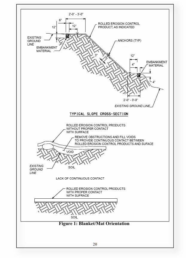
● Place ECB after slope, swale, or channel has been graded and dressed to define flow area and after seed has been applied per Section ST.1.SEED. See Figure 1 for typical blanket orientation for various applications.
● ECB should be installed to conform to the shape of the soil surface.
● Unroll, place, and anchor evenly and smoothly without stretching to ensure contact with soil surface at all points.
● If staples are used, drive flush with soil surface. ● Slope surface shall be free of rocks, clods, sticks, and grass. ● Use appropriate anchoring devices and follow installation
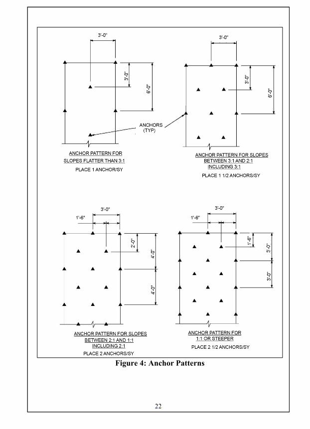
instructions from manufacturer. If installation instructions are not provided by the manufacturer, refer to Figures 1, 2, 3, and 4 for typical guidance.
20
Figure 1: Blanket/Mat Orientation

21
Figure 2: Anchor Trench
Figure 3: Check Slot
22
Figure 4: Anchor Patterns

23
MAINTAINING BMPs:
● Blanket areas shall be inspected weekly and after each runoff event until perennial vegetation is established to a minimum uniform 70% coverage throughout the blanketed area. Damaged or displaced blankets shall be restored within 4 calendar days. Maintenance and inspection of the BMP must be continued until the site is permanently stabilized.
● Perform all preventive and remedial maintenance work, including clean-out, repair, replacement, regrading, reseeding, remulching, and renetting immediately following inspection.
● If the BMP fails to perform as expected, the situation must be addressed immediately with replacement BMPs or modifications of those installed.

24
TURF REINFORCEMENT MAT (TRM) ST.7.TRM
Alternative BMPs: ST.5.ROCK, Companion BMPs: ST.8.PREP
DEFINITION: A type of geosynthetic matting which provides long term non-degradable protection to stabilize soil surfaces and allow vegetation to germinate through the mat.
PURPOSE: TRMs can be used to provide immediate erosion protection while permanent vegetation becomes established because vegetation is allowed to germinate through the mat.
APPLICATION, METHODS, AND PROCEDURES: ● TRM can be used on slopes 1H:1V or flatter. ● Where a TRM is needed to aid in establishment of vegetation,
the application of the TRM is followed by application of soil and a prescribed seed mix, see Section ST.1.SEED.
● TRM should be placed so that there is intimate contact with the soil surface. See Figure 5.
Figure 5: TRM and Soil Contact
TURF REINFORECMENT MAT (TRM) ST.7.TRM

25
● Install TRMs per manufacturer’s instructions. If installation instructions are not provided by the manufacturer, refer to Figures 1, 2, 3, and 4 in Section ST.6.ECB for typical guidance.
MAINTAINING BMPs:
● Maintenance and inspection of the BMP must be continued until the site is permanently stabilized.
● Perform all preventive and remedial maintenance work, including clean-out, repair, replacement, regrading, reseeding, remulching, and renetting immediately following inspection.
● If the BMP fails to perform as expected, the situation must be addressed immediately with replacement BMPs or modifications of those installed.

26
Alternative BMPs: None Companion BMPs: ST.1.SEED, ST.3.MLCH, ST.4.HABK, ST.6.ECB, ST.7.TRM
DEFINITION: Provide a rough soil surface.
PURPOSE: To aid in the establishment of vegetation, reduce runoff velocity, increase infiltration, and reduce erosion on slopes.
APPLICATION, METHODS, AND PROCEDURES: ● There are four primary methods of surface preparation:
Surface Roughening, Tracking Slopes, Stair-Step Grading, and Grooving Slopes.
● For slopes that are steeper than 3H:1V, after preparation, an ECB or TRM should be applied instead of mulch (except Bonded Fiber Matrix). For application, see appropriate BMP sections in this guide.
● Not needed if there is a stable rock face.
Surface Roughening ● Surface Roughening is the practice of providing a rough soil
surface with horizontal depressions for the purpose of reducing velocity, increasing infiltration, aiding the establishment of vegetation, and reducing erosion.
● This method of surface preparation is suitable for applying seed, mulch, or ECBs if slope is to rough, ECB will not apply well to the soil surface.
● Apply seed to roughened slopes per Section ST.1.SEED. ● For temporary stabilization on prepared slopes or in situations
where there is no opportunity for seed to germinate and establish, apply mulch or ECBs as specified in applicable BMP sections of this guide.
Tracking Slopes ● Tracking Slopes (Figure 6) consists of leaving cleated track
marks parallel to contour by running machinery with cleated tracks up and down a slope. If a bulldozer is used the blade should be up.
SURFACE PREPARATION ST.8.PREPK
27
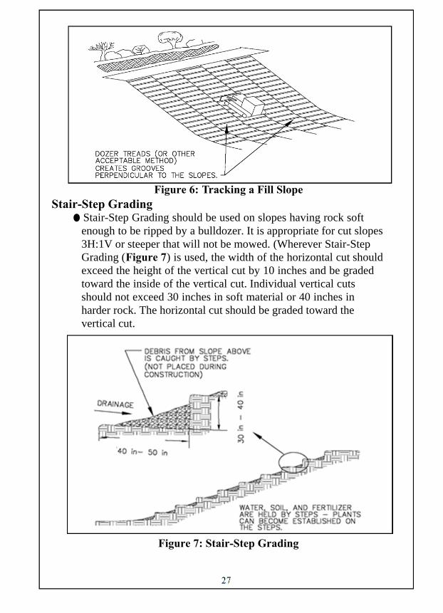
Figure 6: Tracking a Fill Slope Stair-Step Grading
● Stair-Step Grading should be used on slopes having rock soft enough to be ripped by a bulldozer. It is appropriate for cut slopes 3H:1V or steeper that will not be mowed. (Wherever Stair-Step Grading (Figure 7) is used, the width of the horizontal cut should exceed the height of the vertical cut by 10 inches and be graded toward the inside of the vertical cut. Individual vertical cuts should not exceed 30 inches in soft material or 40 inches in harder rock. The horizontal cut should be graded toward the vertical cut.
Figure 7: Stair-Step Grading

28
Grooving Slopes ● Grooving Slopes consists of using machinery to create depressions parallel to the contour along the slope. ● Grooving may be done with discs, tillers, or harrows on softer
materials and on slopes flatter than 3H:1V. The teeth of a front end loader may be used for harder materials.
● Grooves (Figure 8) should be at least 3 inches deep and no more than 15 inches apart.
● Apply seed to roughened slope per Section ST.1.SEED.
Figure 8: Grooving Slopes
MAINTAINING BMPs: ● Maintenance and inspection of the BMP must be continued
until the site is permanently stabilized. ● Perform all preventive and remedial maintenance work,
including repair, replacement, regrading, reseeding, and remulching immediately following inspection.
● If the BMP fails to perform as expected, the situation must be addressed immediately with replacement BMPs or modifications of those installed.
29
Alternative BMPs: None Companion BMPs: Use with one of the following - ST.5.ROCK, ST.11.GABI, ES.4.RFOT, ES.9.OUTL, ES.11.LING (Rock Lining), ES.12.RFIL, ES.14.RCE
DEFINITION: Geotextile material placed under rock used for erosion control. This technique is not a stand-alone BMP. It should be used with other BMP techniques.
PURPOSE: Geotextile lining protects the earth under the rock or other material from eroding as the rock settles into place to protect the area.
APPLICATION, METHODS, AND PROCEDURES: ● Geotextile lining should be placed under rock used for
stabilization or protection. ● Use Geotextile Class 2 for Erosion Control.
Geotextile Class 2-Erosion Control:
● Use Type A or B fabric as specified by the Companion BMP (see list above).
● Remove vegetation, large stones, and other debris from the area to be protected and grade the surface to a relatively smooth condition.
● Excavate areas of soft material and replace with acceptable compacted material.
● Place the fabric on the prepared area in a loose and unstretched condition to minimize shifting, puncturing, or tearing the fabric.
● Join the adjacent edges and ends with a folded seam and sew using a single lock type seam or double chain stitch seam of strength equivalent to the fabric tensile strength.
● Sewing may be done on site or by the manufacturer. ● If overlapping fabric, provide a minimum of 1 foot. ● For underwater placement, overlap a minimum of 3 feet. ● Offset adjacent roll ends a minimum of 5 feet when overlapped.
GEOTEXTILE LINING ST.9.GEOT

30
● Lay and overlap the fabric in the direction shown in Table 7. ● If permitted, anchor the fabric in place by securing pins or other
acceptable methods, along seams or overlaps at the spacing shown in Table 8. Also place securing pins on a maximum 6 foot grid on the unsewn or unlapped portions of the fabric.
Table 7: Fabric Placement
* Place additional pins to secure unlapped portions as specified.
Table 8: Securing Pin Spacing*
● Where slopes are flatter then 6H:1V, securing pins may be eliminated if rock is used to secure the fabric.
● Place rock or other cover material on the fabric as soon as possible so the fabric is not exposed for more than 4 weeks for Type A and 2 weeks for Type B. Prevent rock or other cover material from slippage.
● When placing rocks, do not drop rocks 2 feet or larger in dimension, directly on the fabric from a height greater than 1 foot.
● Do not allow the rock placement to puncture or damage the fabric.
● A minimum 6 inch layer of bedding stone and a greater drop height combination may be used if the combination produces the placement, thickness, gradation, and fabric integrity requirements.
Operation
Slope Stabilization Runoff Protection
and Internal Seepage Piping
Stream Slope Protection
Wave Protection
Direction of fabric laying
Up and down (Parallel with slope
direction)
Parallel to stream flows from upstream to
Up and down (Parallel with slope direction)
Overlap direction
Upslope over downslope
Upstream over downstream and
upslope over
Upslope over downslope
Slope Steeper Then
3H:1V 4H:1V
Flatter Than 4H:1V
Pin spacing along sewn
seams or overlaps
2 ft 3 ft 5 ft

31
MAINTAINING BMPs:
● Maintenance and inspection of the BMP must be continued until the site is permanently stabilized.
● Perform all preventive and remedial maintenance work, including clean-out, repair, replacement, and regrading immediately following inspection.
● If the BMP fails to perform as expected, the situation must be addressed immediately with replacement BMPs or modifications of those installed.

32
Alternative BMPs: ST.1.SEED, ST.4.HABK, ST.5.ROCK, ST.6.ECB, ST.7.TRM Companion BMPs: One or more of the following - ES.6.VEGF, ES.1.STRW, ES.2.SILT, or ES.3.HEVY
DEFINITION: A stabilization method accomplished by compacting soil.
PURPOSE: The rolling process can be used to firmly unite and compact soil particles to resist accelerated erosion. To be used for shoulder work only, not to be used where seeding is to be applied to the surface.
APPLICATION, METHODS, AND PROCEDURES: ● This operation is used following work on unpaved shoulders
that typically have a slope of less than 5 % but not required where the slope is verified at ¾” to 1 ½” per foot.
● The area bordering the shoulder should be protected by a vegetative filter strip or a perimeter control such as a silt barrier fence, heavy duty silt barrier fence, or straw bale barrier. See Sections ES.6.VEGF, ES.2.SILT, ES.3.SSF, ES.1.STRW for specifications.
● Immediately after the disturbed area is prepared, it is preferred to roll with a 5 to 10 ton roller to compact the soil. Rolling alone is not acceptable within 50 feet of surface water. In this instance other erosion control measures must be in place like ES.2.SILT, ES.3.SSF, ES.1.STRW OR ES.15.CFS.
MAINTAINING BMPs: ● Inspect the BMP weekly and after each runoff event until the
area is permanently stabilized by vegetation or some other cover. ● Perform all preventive and remedial maintenance work, includ-
ing repair and regrading, immediately following inspection. ● If the BMP fails to perform as expected the situation must
be addressed immediately with replacement BMPs or modifications of those installed.
ROLLING ST.10.ROLL

33
Alternative BMPs: None Companion BMPs: ST.9.GEOT
DEFINITION: Bundles of rock used to stabilized slopes and stream banks.
PURPOSE: Gabions are used to stabilize stream banks and slopes. Special attention should be made to prevent scour at the upstream and downstream ends of the baskets and to prevent undermining.
APPLICATION, METHODS, AND PROCEDURES: ● Do not grout gabions when used for streambank protection. ● An apron or toe wall is required where the slope wall is installed
adjacent to water. Make the apron approximately two times as wide as the anticipated depth of scour and the toe wall height at least equal to the anticipated depth of scour.
● When gabions are placed on a 1.5:1 side slope or steeper, drive hardwood stakes through the gabions, along the top edge, to anchor the installation. Embed stakes 18” minimum below gabion bottom. Place one stake per gabion box unless more are required to secure the gabion.
● Provide geotextile in accordance with section ST.9.GEOT. Install geotextile material along all interface areas with ground contact.
● On any given level, baskets with exposed faces should be filled prior to filling baskets with no exposed face.
● Base of gabion to be constructed below scour depth next to streams or below frost depth, whichever is greater.
GABIONS ST.11.GABI

34
Figure 9: Gabion Channel Deflector
Figure 10: Gabion

35
GABION SIZES
MATTRESS TYPE
W L H 6’-0” 9’-0” 0’-9” 6’-0” 12’-0” 0’-9”
STANDARD
W L H 3’-0” 6’-0” 1’-0” 3’-0” 12’-0” 1’-0” 3’-0” 9’-0” 1’-0” 3’-0” 6’-0” 3’-0” 3’-0” 9’-0” 3’-0” 3’-0 12’-0” 3’-0”
Figure 10: Gabion (continued)
MAINTAINING BMPs:
● Inspect the BMP weekly and after each runoff event until the
area is permanently stabilized by vegetation or some other cover. ● Perform all preventive and remedial maintenance work, includ-
ing repair and regrading, immediately following inspection. ● If the BMP fails to perform as expected the situation must
be addressed immediately with replacement BMPs or modifications of those installed.
COMMON EROSION AND SEDIMENT CONTROLS

36
Alternative BMPs: ES.2.SILT, ES.3.HEVY Companion BMPs: None
DEFINITION: Temporary barrier consisting of a row of entrenched and anchored straw bales or similar material used to remove sediment from runoff from small areas of disturbed soil.
PURPOSE: Straw bales may be used only in applications involving sheet flow and for durations lasting less than 3 months.
APPLICATION, METHODS, AND PROCEDURES: ● Do not use straw bale barriers in areas of concentrated flow
(e.g. channels, swales, erosion gullies, across pipe outfalls, or as inlet protection, etc.) or in areas where they cannot be properly staked (e.g. paved areas)
● To install a straw bale barrier: (Figures 11, 12, 13 and 14) 1) Excavate the trench. Place and compact embankment
material from the trench excavation on the upslope side of the straw bale barrier.
2) Place straw bale barrier on uniform grade. Extend both ends upslope 8’-0” min at 45 degrees from main straw bale barrier alignment.
3) Place bales so bindings are in the horizontal position. 4) Anchor each bale with two wood stakes minimum. Drive
first stake at an angle and into the previously laid bale to force the bales together.
STRAW BALE BARRIERS ES.1.STRW

37
Figure 11: Straw Bale Barrier
Figure 12: Straw Bale Barrier Staking
● Install downslope of all disturbances, in existing ground, and parallel to existing contours.
Figure 13: Straw Bale Barrier Placement
38
.
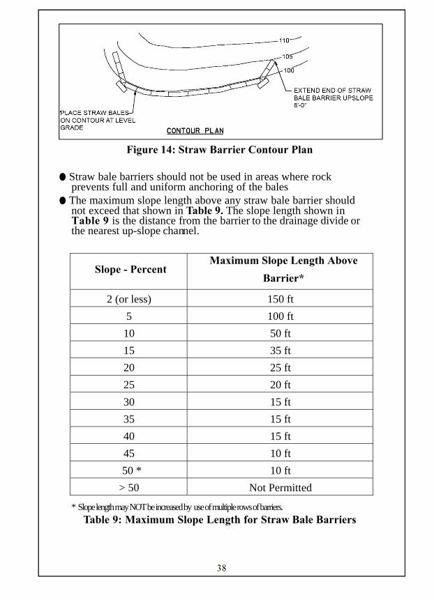
Figure 14: Straw Barrier Contour Plan
● Straw bale barriers should not be used in areas where rock prevents full and uniform anchoring of the bales
● The maximum slope length above any straw bale barrier should not exceed that shown in Table 9. The slope length shown in Table 9 is the distance from the barrier to the drainage divide or the nearest up-slope channel.
* Slope length may NOT be increased by use of multiple rows of barriers.
Table 9: Maximum Slope Length for Straw Bale Barriers
Slope - Percent Maximum Slope Length Above
Barrier*
2 (or less) 150 ft
5 100 ft
10 50 ft
15 35 ft
20 25 ft
25 20 ft
30 15 ft
35 15 ft
40 15 ft
45 10 ft
50 * 10 ft
> 50 Not Permitted

39
MAINTAINING BMPs:
● Maintenance and inspection of the BMP must be continued until the site is permanently stabilized.
● Inspect the BMP weekly and after each runoff event. ● Perform all preventive and remedial maintenance work,
including clean-out, repair, and replacement immediately following inspection.
● Remove/replace straw bale barrier every three months when directed or when no longer needed. Properly dispose of the straw, posts and sediment.
● Remove sediment accumulation when the depth of sediment equals 3 inches above the compacted embankment material.
● Replace undercut and overtopped sections of the straw bale barrier with a Rock Filter Outlet (ES.4.RFOT)
● Sediment deposits left after removal of barriers should be contoured to the existing grade and seeded.
● Damaged or deteriorated bales shall be replaced immediately upon inspection.
● Bales shall be removed when the tributary area has been permanently stabilized.
40
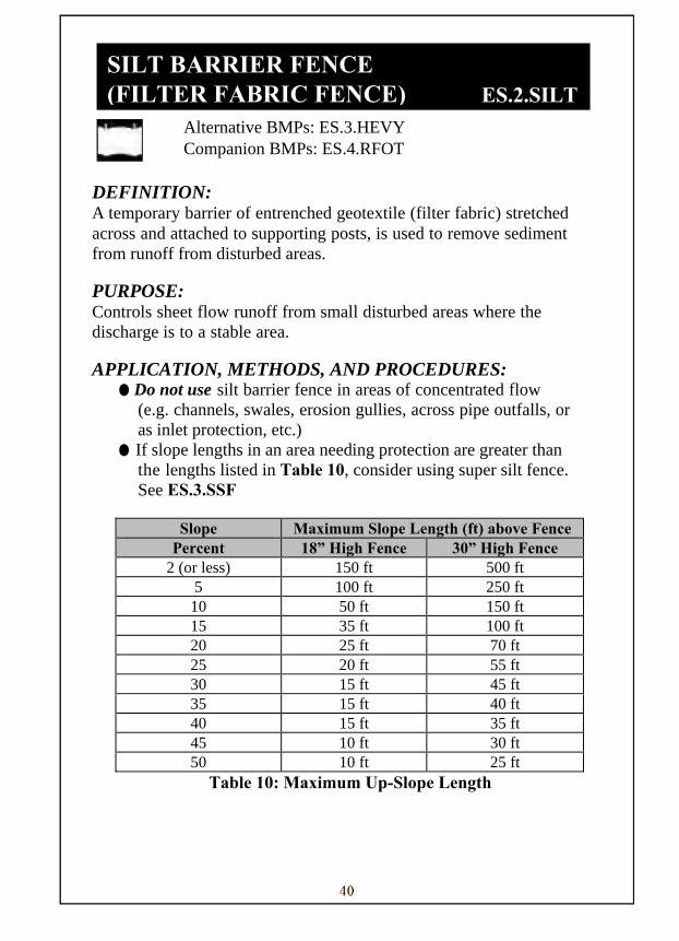
SILT BARRIER FENCE Alternative BMPs: ES.3.HEVY Companion BMPs: ES.4.RFOT
DEFINITION: A temporary barrier of entrenched geotextile (filter fabric) stretched across and attached to supporting posts, is used to remove sediment from runoff from disturbed areas.
PURPOSE: Controls sheet flow runoff from small disturbed areas where the discharge is to a stable area.
APPLICATION, METHODS, AND PROCEDURES: ● Do not use silt barrier fence in areas of concentrated flow
(e.g. channels, swales, erosion gullies, across pipe outfalls, or as inlet protection, etc.)
● If slope lengths in an area needing protection are greater than the lengths listed in Table 10, consider using super silt fence. See ES.3.SSF
Slope Maximum Slope Length (ft) above Fence
Percent 18” High Fence 30” High Fence 2 (or less) 150 ft 500 ft
5 100 ft 250 ft 10 50 ft 150 ft 15 35 ft 100 ft 20 25 ft 70 ft 25 20 ft 55 ft 30 15 ft 45 ft 35 15 ft 40 ft 40 15 ft 35 ft 45 10 ft 30 ft 50 10 ft 25 ft
Table 10: Maximum Up-Slope Length
SILT BARRIER FENCE (FILTER FABRIC FENCE) ES.2.SILT
41
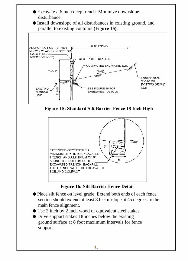
● Excavate a 6 inch deep trench. Minimize downslope disturbance.
● Install downslope of all disturbances in existing ground, and parallel to existing contours (Figure 15).
for instructions.
Figure 15: Standard Silt Barrier Fence 18 Inch High
Figure 16: Silt Barrier Fence Detail
● Place silt fence on level grade. Extend both ends of each fence section should extend at least 8 feet upslope at 45 degrees to the main fence alignment.
● Use 2 inch by 2 inch wood or equivalent steel stakes. ● Drive support stakes 18 inches below the existing
ground surface at 8 foot maximum intervals for fence support.

42
● Silt Barrier Fence shall be installed with the required post spacing as shown in Figure 17.
Figure 17: Silt Barrier Fence
Table 11 – Silt Barrier Fence Geotextile Selection
Figure 18: – Silt Barrier Fence Joining Detail
43
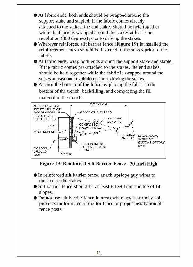
● At fabric ends, both ends should be wrapped around the support stake and stapled. If the fabric comes already attached to the stakes, the end stakes should be held together while the fabric is wrapped around the stakes at least one revolution (360 degrees) prior to driving the stakes.
● Wherever reinforced silt barrier fence (Figure 19) is installed the reinforcement mesh should be fastened to the stakes prior to the fabric.
● At fabric ends, wrap both ends around the support stake and staple. If the fabric comes pre-attached to the stakes, the end stakes should be held together while the fabric is wrapped around the stakes at least one revolution prior to driving the stakes.
● Anchor the bottom of the fence by placing the fabric in the bottom of the trench, backfilling, and compacting the fill material in the trench.
Figure 19: Reinforced Silt Barrier Fence - 30 Inch High
● In reinforced silt barrier fence, attach upslope guy wires to the side of the stakes.
● Silt barrier fence should be at least 8 feet from the toe of fill slopes.
● Do not use silt barrier fence in areas where rock or rocky soil prevents uniform anchoring for fence or proper installation of fence posts.

44
MAINTAINING BMPs:
● Maintenance and inspection of the BMP must be continued
until the site is permanently stabilized. ● Inspect the BMP weekly and after each runoff event. ● Perform all preventive and remedial maintenance work,
including clean-out, repair, and replacement immediately following inspection.
● If the BMP fails to perform as expected, the situation must be addressed immediately with replacement BMPs or modifications of those installed.
● Sediment should be removed when accumulations reach 1/2 the above ground height of the fence.
● Adhere to the manufacturer’s recommendations relative to required geotextile replacement due to weathering.
● Replace undercut and overtopped sections of the fence with a Rock Filter Outlet. Rock Filter Outlet should be installed along the silt barrier fence at points of frequent failures. See ES.4 RFIL
● Fence shall be removed and properly disposed of when tributary area is permanently stabilized.
45
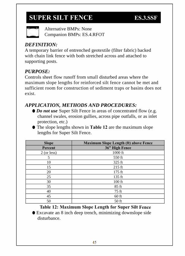
SUPER SILT FENCE ES.3.SSF Alternative BMPs: None Companion BMPs: ES.4.RFOT
DEFINITION: A temporary barrier of entrenched geotextile (filter fabric) backed with chain link fence with both stretched across and attached to supporting posts.
PURPOSE: Controls sheet flow runoff from small disturbed areas where the maximum slope lengths for reinforced silt fence cannot be met and sufficient room for construction of sediment traps or basins does not exist. APPLICATION, METHODS AND PROCEDURES:
● Do not use Super Silt Fence in areas of concentrated flow (e.g. channel swales, erosion gullies, across pipe outfalls, or as inlet protection, etc.)
● The slope lengths shown in Table 12 are the maximum slope lengths for Super Silt Fence.
Slope Maximum Slope Length (ft) above Fence
Percent 36” High Fence 2 (or less) 1000 ft
5 550 ft 10 325 ft 15 215 ft 20 175 ft 25 135 ft 30 100 ft 35 85 ft 40 75 ft 45 60 ft 50 50 ft
Table 12: Maximum Slope Length for Super Silt Fence ● Excavate an 8 inch deep trench, minimizing downslope side
disturbance.
SUPER SILT FENCE ES.3.SSF
46
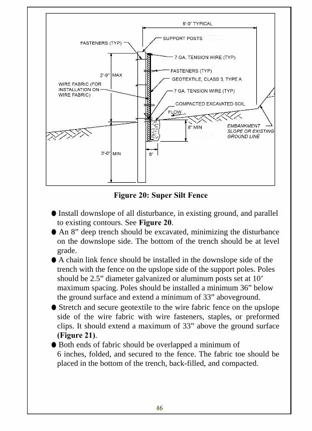
Figure 20: Super Silt Fence
● Install downslope of all disturbance, in existing ground, and parallel
to existing contours. See Figure 20. ● An 8” deep trench should be excavated, minimizing the disturbance
on the downslope side. The bottom of the trench should be at level grade.
● A chain link fence should be installed in the downslope side of the trench with the fence on the upslope side of the support poles. Poles should be 2.5” diameter galvanized or aluminum posts set at 10’ maximum spacing. Poles should be installed a minimum 36” below the ground surface and extend a minimum of 33” aboveground.
● Stretch and secure geotextile to the wire fabric fence on the upslope side of the wire fabric with wire fasteners, staples, or preformed clips. It should extend a maximum of 33” above the ground surface (Figure 21).
● Both ends of fabric should be overlapped a minimum of 6 inches, folded, and secured to the fence. The fabric toe should be
placed in the bottom of the trench, back-filled, and compacted.
47
● Both ends of each fence section should extend at least 8 feet upslope
at approximately 45 degrees to the main fence alignment. ● Do not use Super Silt Fence in areas where rock or rocky soil
prevents uniform anchoring of fence or proper installation of fence posts.
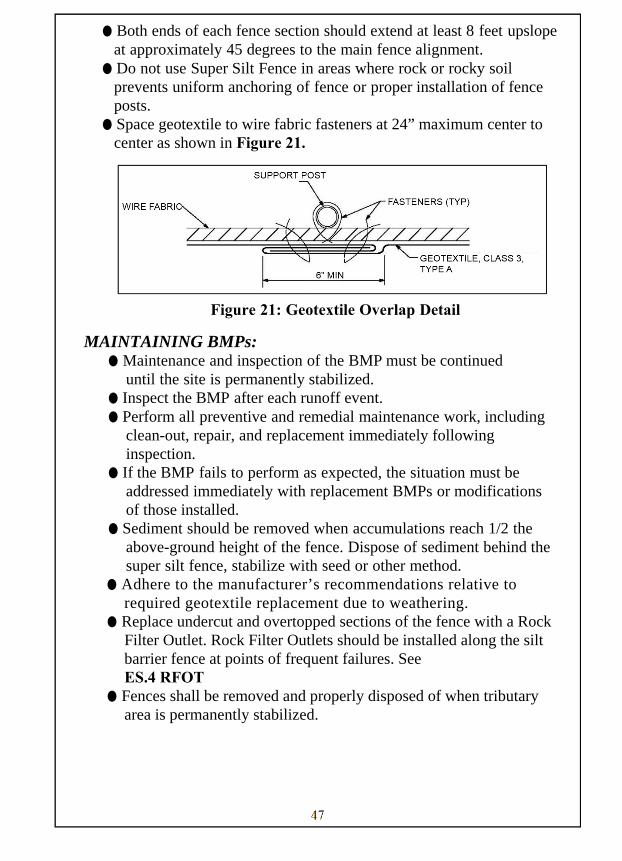
● Space geotextile to wire fabric fasteners at 24” maximum center to center as shown in Figure 21.
Figure 21: Geotextile Overlap Detail
MAINTAINING BMPs: ● Maintenance and inspection of the BMP must be continued
until the site is permanently stabilized. ● Inspect the BMP after each runoff event. ● Perform all preventive and remedial maintenance work, including
clean-out, repair, and replacement immediately following inspection.
● If the BMP fails to perform as expected, the situation must be addressed immediately with replacement BMPs or modifications of those installed.
● Sediment should be removed when accumulations reach 1/2 the above-ground height of the fence. Dispose of sediment behind the super silt fence, stabilize with seed or other method.
● Adhere to the manufacturer’s recommendations relative to required geotextile replacement due to weathering.
● Replace undercut and overtopped sections of the fence with a Rock Filter Outlet. Rock Filter Outlets should be installed along the silt barrier fence at points of frequent failures. See ES.4 RFOT
● Fences shall be removed and properly disposed of when tributary area is permanently stabilized.

48
Alternative BMPs: None Companion BMPs: ES.2.SILT, ES.3.HEVY
DEFINITION: Small, temporary, stone for fixing washouts in Silt Barrier Fence and Super Silt Barrier Fence.
PURPOSE: Rock Filter Outlets may be used to address problems of concentrated flows to sediment barriers. APPLICATION, METHODS, AND PROCEDURES:
● A rock filter outlet shall be installed where failure of a silt fence or straw bale barrier has occurred due to concentrated flow unless that concentrated flow can otherwise be directed away from the barrier.
Figure 22: Rock Filter Outlet
ROCK FILTER OUTLET ES.4.RFOT
49
MAINTAINING BMPs: ● Maintenance and inspection of the BMP must be continued until the site is permanently stabilized. ● Inspect the BMP weekly and after each runoff event. ● Perform all preventive and remedial maintenance work, including
clean-out, repair, and replacement immediately following inspection.
● If the BMP fails to perform as expected, the situation must be addressed immediately with replacement BMPs or modifications of those installed.
● During inspection, observe if water is eroding around the sides of the Rock Filter Outlet. If so, address immediately.
● Remove sediment when accumulation reaches 1/3 the height of the outlet.

50
Alternative BMPs: None Companion BMPs: None
DEFINITION: Methods of protecting storm sewer systems in disturbed areas so that sediment doesn’t enter the drainage system.
PURPOSE: To filter sediment out of the runoff before the water enters the storm sewer system.
APPLICATION, METHODS, AND PROCEDURES:
● Use inlet protection when storm drains are made operational before the drainage area is stabilized.
● Do not use on paved roads where ponding may cause traffic hazards. Protection should not be used where inlets are at low points on traveled roadways.
● Three methods of inlet protection are addressed in this section:
Storm Inlet Protection and Berm(s) ● Temporary Earthen Berms or Sandbags can be used for all inlet
protection. ● Use Berms as required. Protection to be used inside project site area
where there is no traffic. ● Do not use inlet protection on roadways where ponding water or
inlet protection may be hazardous to vehicular traffic. ● Earthen Berm on the roadway shall be maintained until roadway is
stoned. Road subbase berm on the roadway shall be maintained until roadway is paved. Earthen Berm in the channel shall be maintained until permanent stabilization is completed.
● Maximum drainage areas is 1 acre for stone inlet protection.
STORM INLET PROTECTION ES.5.INLT
51
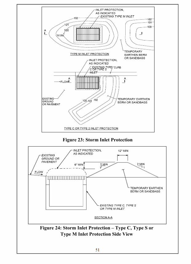
Figure 23: Storm Inlet Protection
Figure 24: Storm Inlet Protection – Type C, Type S or
Type M Inlet Protection Side View
52
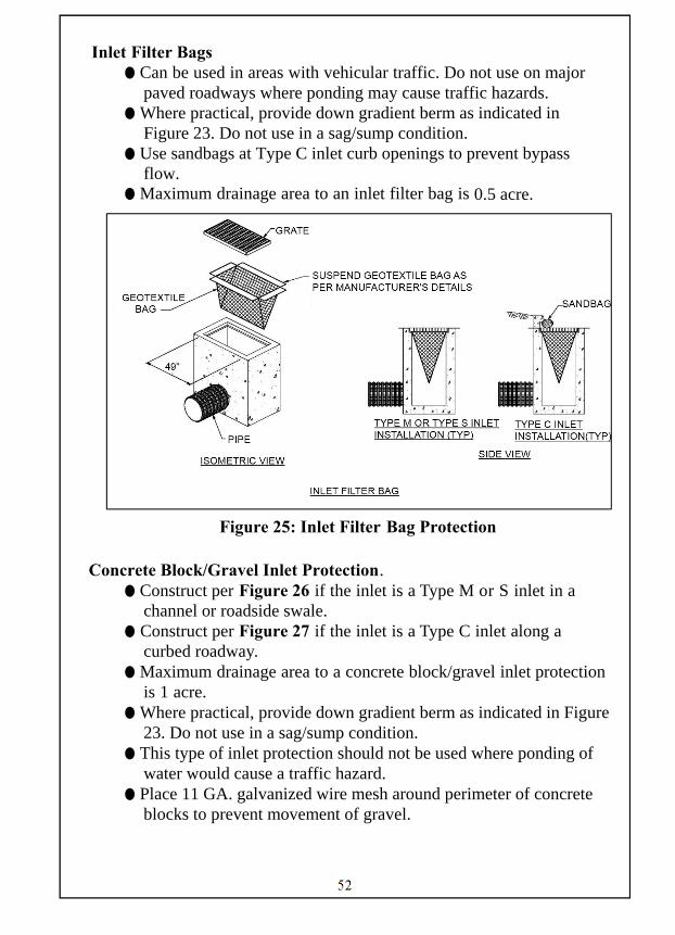
Inlet Filter Bags ● Can be used in areas with vehicular traffic. Do not use on major
paved roadways where ponding may cause traffic hazards. ● Where practical, provide down gradient berm as indicated in
Figure 23. Do not use in a sag/sump condition. ● Use sandbags at Type C inlet curb openings to prevent bypass
flow. ● Maximum drainage area to an inlet filter bag is 0.5 acre.
Figure 25: Inlet Filter Bag Protection
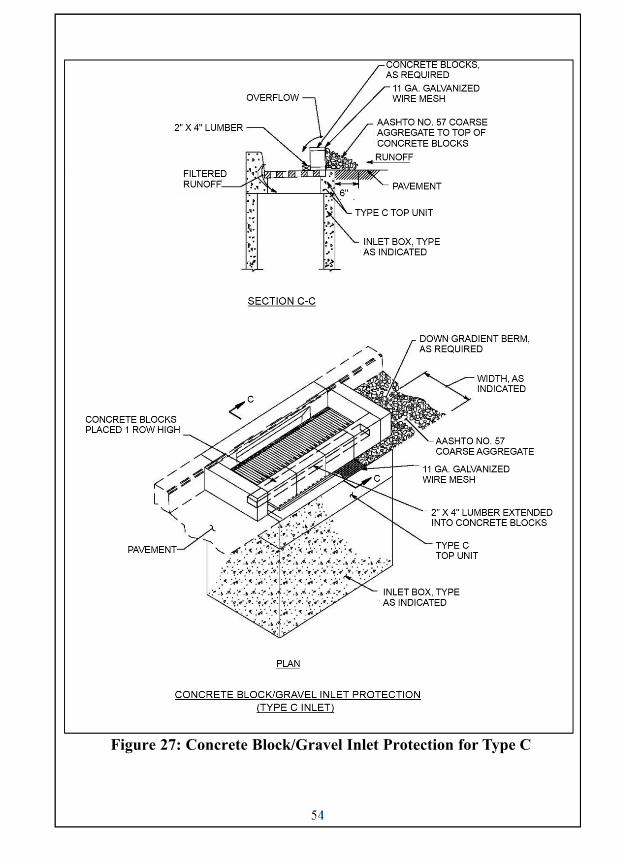
Concrete Block/Gravel Inlet Protection.
● Construct per Figure 26 if the inlet is a Type M or S inlet in a channel or roadside swale.
● Construct per Figure 27 if the inlet is a Type C inlet along a curbed roadway.
● Maximum drainage area to a concrete block/gravel inlet protection is 1 acre.
● Where practical, provide down gradient berm as indicated in Figure 23. Do not use in a sag/sump condition.
● This type of inlet protection should not be used where ponding of water would cause a traffic hazard.
● Place 11 GA. galvanized wire mesh around perimeter of concrete blocks to prevent movement of gravel.
53
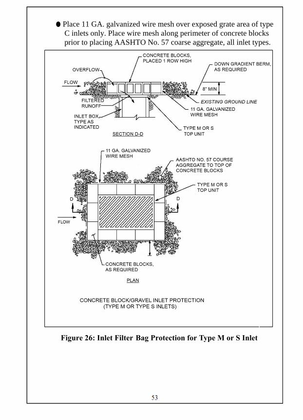
● Place 11 GA. galvanized wire mesh over exposed grate area of type C inlets only. Place wire mesh along perimeter of concrete blocks prior to placing AASHTO No. 57 coarse aggregate, all inlet types.
Figure 26: Inlet Filter Bag Protection for Type M or S Inlet
54
Figure 27: Concrete Block/Gravel Inlet Protection for Type C
55
MAINTAINING BMPs:
● Maintenance and inspection of the BMP must be continued until the site is permanently stabilized.
● Inspect the BMP and remove sediment weekly and after each runoff event. Use care to not damage inlet filter bag when removing sediment. Maintain as required to ensure proper functioning of inlet filter bags.
● Perform all preventive and remedial maintenance work, including clean-out, repair, and replacement immediately following inspection.
● If the BMP fails to perform as expected, the situation must be addressed immediately with replacement BMPs or modifications of those installed.
● Dispose the removed sediment in a suitable area, in a manner that will not erode.
● When the contributing drainage area is stabilized remove the inlet protection.
● Inlet filter bags shall be emptied and rinsed or replaced when half full or when flow capacity has been reduced so as to cause flooding or bypassing of the inlet. Damaged or clogged bags shall be replaced. A supply shall be maintained on site for replacement of bags. Dispose of accumulated sediment as well as all used bags according to the plan notes.
● Replace and satisfactorily dispose of clogged filter stone (AASHTO No. 57) coarse aggregate. Rake periodically to increase infiltration.
● When concrete blocks and gravel are removed, stabilize any bare areas.
56
Alternative BMPs: None Companion BMPs: None
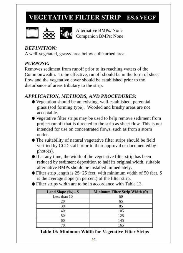
DEFINITION: A well-vegetated, grassy area below a disturbed area.
PURPOSE: Removes sediment from runoff prior to its reaching waters of the Commonwealth. To be effective, runoff should be in the form of sheet flow and the vegetative cover should be established prior to the disturbance of areas tributary to the strip.
APPLICATION, METHODS, AND PROCEDURES:
● Vegetation should be an existing, well-established, perennial grass (sod forming type). Wooded and brushy areas are not acceptable.
● Vegetative filter strips may be used to help remove sediment from project runoff that is directed to the strip as sheet flow. This is not intended for use on concentrated flows, such as from a storm outlet.
● The suitability of natural vegetative filter strips should be field verified by CCD staff prior to their approval or documented by photo(s).
● If at any time, the width of the vegetative filter strip has been reduced by sediment deposition to half its original width, suitable alternative BMPs should be installed immediately.
● Filter strip length is 2S+25 feet, with minimum width of 50 feet. S is the average slope (in percent) of the filter strip.
● Filter strips width are to be in accordance with Table 13.
Table 13: Minimum Width for Vegetative Filter Strips
Land Slope (%) - S Minimum Filter Strip Width (ft) Less than 10 50
20 65 30 85 40 105 50 125 60 145 70 165
VEGETATIVE FILTER STRIP ES.6.VEGF

57
MAINTAINING BMPs: ● Maintenance and inspection of the BMP must be continued
until the site is permanently stabilized. ● Inspect the BMP weekly and after each runoff event. ● Perform all preventive and remedial maintenance work. ● If the BMP fails to perform as expected, the situation must be
addressed immediately with replacement BMPs or modifications of those installed.
● Aerate as necessary in compacted soils. ● Lime and fertilizer as necessary to maintain thick vegetation. ● Eroded areas should be filled in and reseeded immediately,
and the cause for erosion should be determined and alleviated. ● If the width of the filter strip is reduced by sediment deposition to
1/2 its original width, suitable alternative BMPs should be installed immediately.
58
Alternative BMPs: None Companion BMPs: ST.1.SEED, ST.3.MLCH
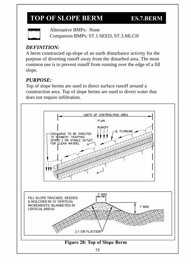
DEFINITION: A berm constructed up-slope of an earth disturbance activity for the purpose of diverting runoff away from the disturbed area. The most common use is to prevent runoff from running over the edge of a fill slope.
PURPOSE: Top of slope berms are used to direct surface runoff around a construction area. Top of slope berms are used to divert water that does not require infiltration.
Figure 28: Top of Slope Berm
TOP OF SLOPE BERM ES.7.BERM

59
Figure 29: Top of Slope Berm- Section A View
Table 14: Berm Dimensions
Table 15: Stabilization Methods for Top of Slope Berms
Channel Grade
Type A Type B
1 0.5%-3.0% Seed & straw
mulch Seed & straw mulch
2 3.1%-5.0% Seed & straw
mulch Seed with ECB
3 5.1%-8.0% Seed with ECB R-4 Riprap
4 8.1%-20% R-4 Riprap Engineered design
60
APPLICATION, METHODS, AND PROCEDURES: ● Top of slope berms are appropriate where surface flow may
cause damage to down gradient slopes.
● Berms may be used to redirect runoff from uphill areas that may interfere with the efficient operation of other stormwater BMPs.
● The maximum tributary are to a berm should be 5.0 acres unless otherwise permitted by the local CCD.
● Top of slope berms shall be installed and stabilized prior to general clearing and grubbing operations.
● Top of slope berms shall be constructed from on-site compacting material. Compost material may also be considered as approved and specified by DEP.
● All berms should be compacted by earth-moving equipment. ● All berms should drain to an outlet that functions with minimum
erosion. If the channel behind the berm or drainage area above the berm is not adequately stabilized, runoff shall be conveyed to a sediment trapping device.
● Runoff diverted by berms should be directed to a temporary slope pipe or collector channel to be conveyed below the disturbed area where the flow can re-enter the natural drainage course.
● Figures 28 and 29 show typical layout of berms. ● Channel behind berm shall have positive grade to outlet and an
appropriate protective lining. ● Table 15 shows stabilization methods for berm types and channel
slopes. ● The top width may be wider and side slopes flatter to
accommodate crossing construction traffic.

61
MAINTAINING BMPs: ● Maintenance and inspection of the BMP must be continued
until the site is permanently stabilized. ● Inspect the BMP weekly and after each runoff event. ● Perform all preventive and remedial maintenance work,
including clean-out, repair, replacement, regrading, reseeding, remulching, and rematting immediately following inspection.
● If the BMP fails to perform as expected, the situation must be addressed immediately with replacement BMPs or modifications of those installed.
● Check for uniformity and obstacles which restrict flow. Reshape or remove as necessary.
● Top-of-slope berms should be maintained with successive lifts. As fill is being constructed, the berm should be raised prior to placement of the next fill lift.
● Temporary berms shall be placed, maintained, and adjusted continuously until 90% vegetative growth is established on the exterior slopes with permanent storm drainage features functioning. ● Remove Top-of-slope berms when fill slopes are stabilized and the
permanent drainage system is in place.

62
Alternative BMPs: None Companion BMPs: ES.7.BERM
DEFINITION: A flexible pipe placed over an erodible slope.
PURPOSE: To convey runoff down steep slopes, protecting those slopes from accelerated erosion. APPLICATION, METHODS, AND PROCEDURES:
● Wherever temporary slope pipes are used to convey discharges from sediment basins, they should be connected to the principal spillway barrel outlet.
● Whenever temporary pipes are used to convey runoff from unstabilized areas, they should discharge into a sediment basin, trap or collector channel. The end of a pipe discharging to a collector channel should be oriented to facilitate flow in the channel and located so as to avoid obstructing flow from any upgradient section of the channel.
● Construct as shown in Figures 30, 31, and 32.
Figure 30: Temporary Slope Pipe
TEMPORARY SLOPE PIPE ES.8.PIPE
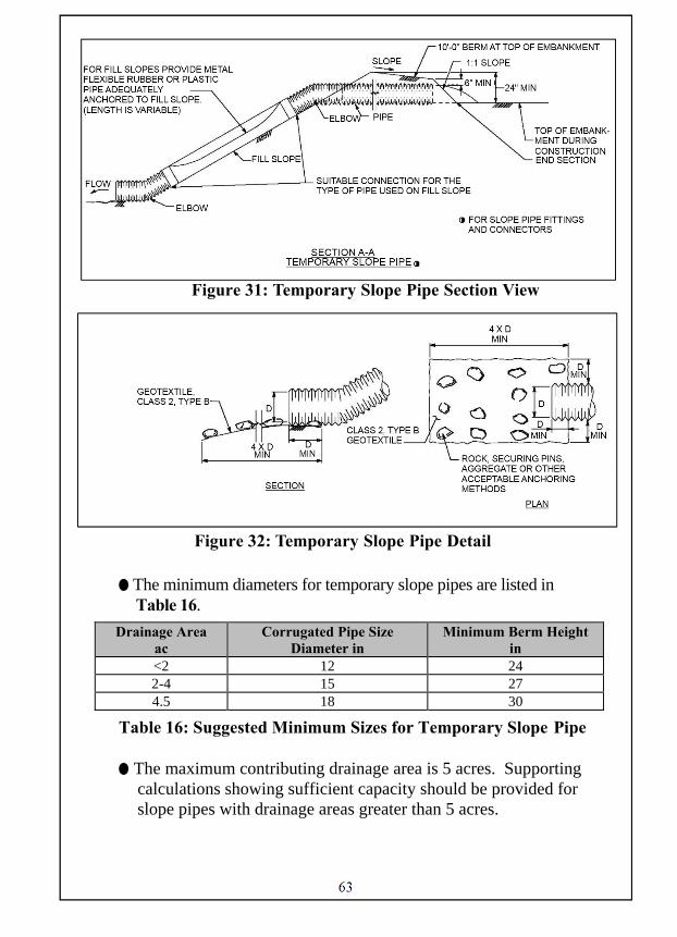
63
Figure 31: Temporary Slope Pipe Section View
Figure 32: Temporary Slope Pipe Detail
● The minimum diameters for temporary slope pipes are listed in Table 16.
Table 16: Suggested Minimum Sizes for Temporary Slope Pipe
● The maximum contributing drainage area is 5 acres. Supporting calculations showing sufficient capacity should be provided for slope pipes with drainage areas greater than 5 acres.
Drainage Area ac
Corrugated Pipe Size Diameter in
Minimum Berm Height in
<2 12 24 2-4 15 27 4.5 18 30
64
● The entrance of the pipe should have a flared end section with a 6 inch toe plate.
● The pipe should be heavy duty flexible pipe or corrugated metal and should be securely staked to the slope.
● The pipe should be securely staked to the slope. The maximum distance between the anchor stakes is 10 feet.
● The connections should be watertight. ● Add outlet protection as needed.
MAINTAINING BMPs:
● Maintenance and inspection of the BMP must be continued until the site is permanently stabilized.
● Inspect the BMP weekly and after each runoff event. ● Damaged pipe sections shall be replaced within 24 hours. Leaking
connections shall be repaired immediately. ● Perform all preventive and remedial maintenance work, including
clean-out, repair, and replacement immediately following inspection.
● If the BMP fails to perform as expected, the situation must be addressed immediately with replacement BMPs or modifications of those installed.
● Clean and repair all clogged or leaking pipes as necessary. Remove accumulated sediment from the entrance or exit of each slope pipe and dispose of in an area approved by the Local Conservation District.

65
Alternative BMPs: None Companion BMPs: ST.9.GEOT
DEFINITION: An energy dissipater constructed in the area of an outfall to provide scour protection for discharges from pipes and channels.
PURPOSE: To prevent erosion in areas immediately downstream of pipe and channel outlets.
APPLICATION, METHODS, AND PROCEDURES: ● Place outlet protection at the outlet of any concentrated flow,
such as outlets of storm drains, ponds, temporary slope pipes, ditches, or other conveyances.
● Rock Aprons may be used to prevent scour at pipe or channel outfalls where anticipated discharge velocities do not exceed 17.0 feet per second and there is sufficient room to construct the apron.
● Three type of outlet protection are addressed in this section, Rock Apron, Rock Basin, Rock Energy Dissipater:
Rock Apron
● Rock aprons should be constructed on level or as close to level ground as reasonably possible based on site conditions.
● Geotextile materials should be provided along all interface areas with ground contact.
● Aprons should be oriented so that the discharge enters the receiving channel at less than 90 degrees to the channel flow direction. In no case should the discharge enter the channel at an angle greater than 90 degrees to the channel flow direction.
● Riprap thickness shall be 1.5 times the maximum stone size. ● Evenly distribute rock on the geotextile leaving a minimum amount
of voids and without tearing the geotextile. ● Do not place rock by dumping from chutes, or similar methods. ● Rearrange individual rocks for uniform distribution. ● If necessary, after rock is in place, saturate with water, then
completely fill the voids between pieces with grout for at least a depth of 6 inches and sweep the surface with a stiff broom.
OUTLET PROTECTION ES.9.OUTL

66
● Do not place grout when air temperature is below freezing. In hot, dry weather, protect grouted rock from excessive heat and keep moist for at least 3 days after grouting using saturated burlap.
● The specific pipe end treatment will determine the placement of the rock apron. Utilize Figure 33, 34, 35 and 36 to determine the appropriate rock apron.
Figure 33: Rock Apron – Flat Area with Pipe
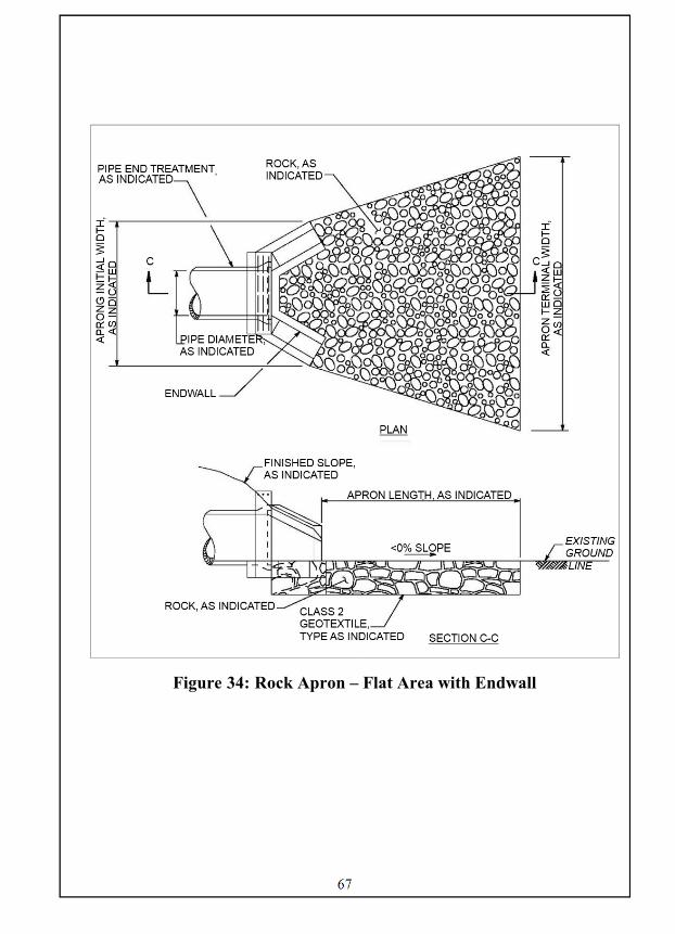
67
Figure 34: Rock Apron – Flat Area with Endwall
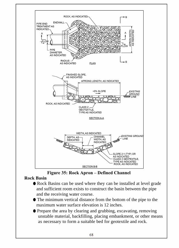
68
Figure 35: Rock Apron – Defined Channel
Rock Basin ● Rock Basins can be used where they can be installed at level grade
and sufficient room exists to construct the basin between the pipe and the receiving water course.
● The minimum vertical distance from the bottom of the pipe to the maximum water surface elevation is 12 inches.
● Prepare the area by clearing and grubbing, excavating, removing unstable material, backfilling, placing embankment, or other means as necessary to form a suitable bed for geotextile and rock.

69
● Place Class 2, Type A Geotextile according to ST.9.GEOT. ● Place R-7 rock on geotextile. Refer to Appendix A (or Pub. 408)
for rock specifications. ● Evenly distribute rock on the geotextile leaving a minimum
amount of voids and without tearing the geotextile. ● Do not place rock by dumping from chutes, or similar methods. ● Rearrange individual rocks for uniform distribution. ● If necessary, after rock is in place, saturate with water, then
completely fill the voids between pieces with grout for at least a depth of 6 inches and sweep the surface with a stiff broom.
● Do not place grout when air temperature is below freezing. In hot, dry weather, protect grouted rock from excessive heat and keep moist for at least 3 days after grouting using saturated burlap.
● Construct as shown in Figures 36.
Figure 36: Rock Basin
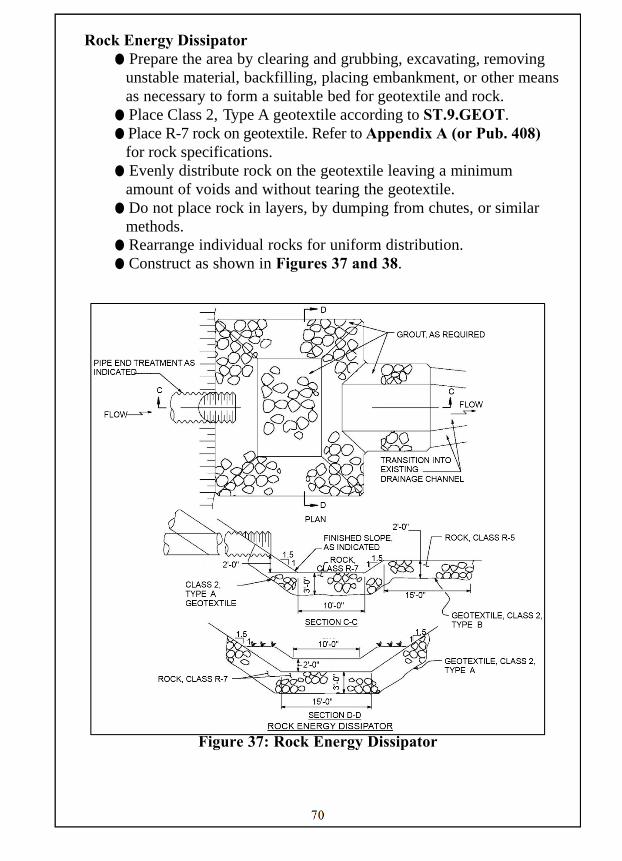
70
Rock Energy Dissipator ● Prepare the area by clearing and grubbing, excavating, removing
unstable material, backfilling, placing embankment, or other means as necessary to form a suitable bed for geotextile and rock.
● Place Class 2, Type A geotextile according to ST.9.GEOT. ● Place R-7 rock on geotextile. Refer to Appendix A (or Pub. 408)
for rock specifications. ● Evenly distribute rock on the geotextile leaving a minimum
amount of voids and without tearing the geotextile. ● Do not place rock in layers, by dumping from chutes, or similar
methods. ● Rearrange individual rocks for uniform distribution. ● Construct as shown in Figures 37 and 38.
Figure 37: Rock Energy Dissipator

71
Figure 38: Paved Rock Energy Dissipator
● If necessary, after rock is in place, saturate with water, then completely fill the voids between pieces with grout for at least a depth of 6 inches and sweep the surface with a stiff broom.
● Do not place grout when air temperature is below freezing. In hot, dry weather, protect grouted rock from excessive heat and keep moist for at least 3 days after grouting using saturated burlap.

72
MAINTAINING BMPs:
● Maintenance and inspection of the BMP must be continued until the site is permanently stabilized.
● Inspect the BMP weekly and after each runoff event. ● Perform all preventive and remedial maintenance work,
including clean-out, repair, replacement, and regrading immediately following inspection.
● If the BMP fails to perform as expected, the situation must be addressed immediately with replacement BMPs or modifications of those installed.
● If scour is discovered at the outlet, enlarge the size of the stone or energy dissipator to protect the eroded area.
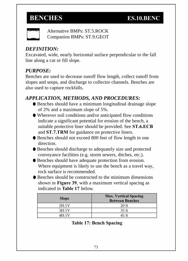
73
Alternative BMPs: ST.5.ROCK Companion BMPs: ST.9.GEOT
DEFINITION: Excavated, wide, nearly horizontal surface perpendicular to the fall line along a cut or fill slope.
PURPOSE: Benches are used to decrease runoff flow length, collect runoff from slopes and seeps, and discharge to collector channels. Benches are also used to capture rockfalls.
APPLICATION, METHODS, AND PROCEDURES: ● Benches should have a minimum longitudinal drainage slope
of 2% and a maximum slope of 5%. ● Wherever soil conditions and/or anticipated flow conditions
indicate a significant potential for erosion of the bench, a suitable protective liner should be provided. See ST.6.ECB and ST.7.TRM for guidance on protective liners.
● Benches should not exceed 800 feet of flow length in one direction.
● Benches should discharge to adequately size and protected conveyance facilities (e.g. storm sewers, ditches, etc.).
● Benches should have adequate protection from erosion. Where equipment is likely to use the bench as a travel way, rock surface is recommended.
● Benches should be constructed to the minimum dimensions shown in Figure 39, with a maximum vertical spacing as indicated in Table 17 below.
Table 17: Bench Spacing
Slope Max. Vertical Spacing
Between Benches 2H:1V 20 ft 3H:1V 35 ft 4H:1V 45 ft
BENCHES ES.10.BENC
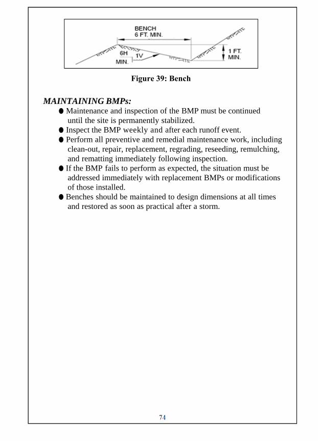
74
Figure 39: Bench
MAINTAINING BMPs: ● Maintenance and inspection of the BMP must be continued
until the site is permanently stabilized. ● Inspect the BMP weekly and after each runoff event. ● Perform all preventive and remedial maintenance work, including
clean-out, repair, replacement, regrading, reseeding, remulching, and rematting immediately following inspection.
● If the BMP fails to perform as expected, the situation must be addressed immediately with replacement BMPs or modifications of those installed.
● Benches should be maintained to design dimensions at all times and restored as soon as practical after a storm.

75
Alternative BMPs: None Companion BMPs: ST.1.SEED, ST.2.TPSL, ST.3.MLCH, ST.5.ROCK, ST.6.ECB, ST.7.TRM
DEFINITION: Protection placed on channel beds and side slopes to prevent accelerated erosion.
PURPOSE: Protect and reinforce soil in channel banks and bottoms from erosive velocities and scour.
APPLICATION, METHODS, AND PROCEDURES: ● Line all channels with an erosion resistant lining before use. ● Vegetation effectively stabilizes most channels and is the
preferred method. ● Options for channel liners include grass, sod, TRM, concrete,
gabions, reno mattress, geotextiles, jute matting, interlocking block, cable concrete, and rock.
● Concrete and rock are not conducive to vegetation establishment and should be used only in areas with highly erosive velocities.
● Install rolled erosion control products in straight sections around channel bend to avoid curling of mat edges. Install rolled erosion control products starting with panel #1.
● Establish and maintain continuous contact between the rolled erosion control products and soil surface as shown in Figure 40.
● See ST.6.ECB if using Erosion Control Blanket as a channel lining.
● See ST.7.TRM if using Turf Reinforcement Mat as a channel lining.
● Concrete lining should be used cautiously because the velocity of the runoff will increase, which may be undesirable. Aesthetics should be considered before deciding to use concrete lining.
CHANNEL LININGS ES.11.LING

76
● See ST.5.ROCK if using rock as a channel lining. Use
geotextile or filter blanket under all rock channel liners with bed slopes greater than 10%. Aesthetics should be considered before deciding on rock lining.
● Construct rock lining as shown in Figures 40, 41 and 42.
Figure 40: Channel Lining Detail

77
Figure 41: Rock Lining - Plan View
Figure 42: Rock Lining
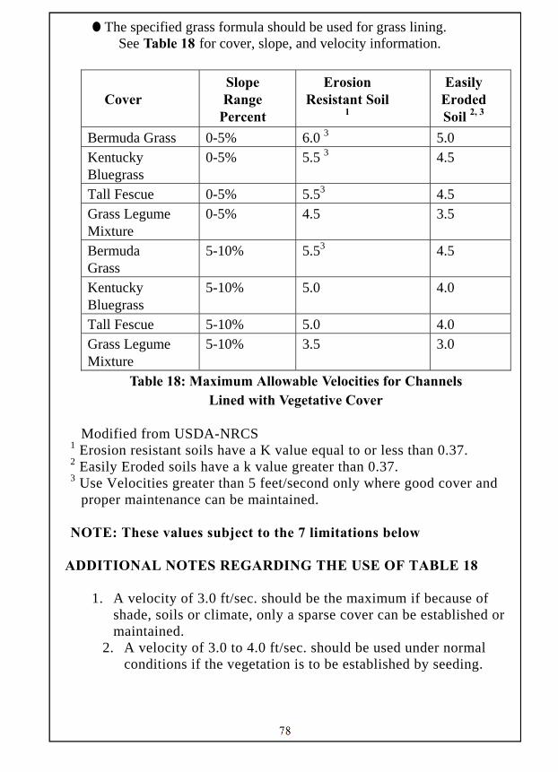
78
● The specified grass formula should be used for grass lining. See Table 18 for cover, slope, and velocity information.
Cover Slope Range
Percent
Erosion Resistant Soil
1
Easily Eroded Soil 2, 3
Bermuda Grass 0-5% 6.0 3 5.0 Kentucky Bluegrass
0-5% 5.5 3 4.5
Tall Fescue 0-5% 5.53 4.5 Grass Legume Mixture
0-5% 4.5 3.5
Bermuda Grass
5-10% 5.53 4.5
Kentucky Bluegrass
5-10% 5.0 4.0
Tall Fescue 5-10% 5.0 4.0 Grass Legume Mixture
5-10% 3.5 3.0
Table 18: Maximum Allowable Velocities for Channels Lined with Vegetative Cover
Modified from USDA-NRCS
1 Erosion resistant soils have a K value equal to or less than 0.37. 2 Easily Eroded soils have a k value greater than 0.37. 3 Use Velocities greater than 5 feet/second only where good cover and
proper maintenance can be maintained. NOTE: These values subject to the 7 limitations below
ADDITIONAL NOTES REGARDING THE USE OF TABLE 18
1. A velocity of 3.0 ft/sec. should be the maximum if because of shade, soils or climate, only a sparse cover can be established or maintained.
2. A velocity of 3.0 to 4.0 ft/sec. should be used under normal conditions if the vegetation is to be established by seeding.
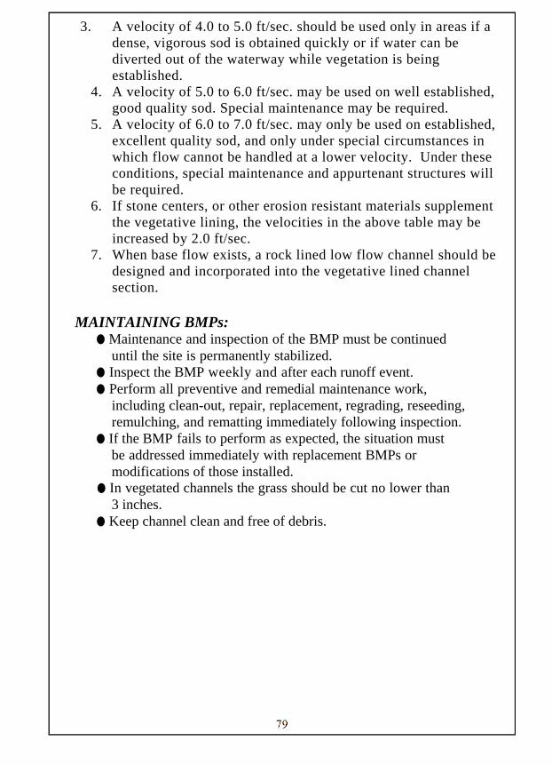
79
3. A velocity of 4.0 to 5.0 ft/sec. should be used only in areas if a
dense, vigorous sod is obtained quickly or if water can be diverted out of the waterway while vegetation is being established.
4. A velocity of 5.0 to 6.0 ft/sec. may be used on well established, good quality sod. Special maintenance may be required.
5. A velocity of 6.0 to 7.0 ft/sec. may only be used on established, excellent quality sod, and only under special circumstances in which flow cannot be handled at a lower velocity. Under these conditions, special maintenance and appurtenant structures will be required.
6. If stone centers, or other erosion resistant materials supplement the vegetative lining, the velocities in the above table may be increased by 2.0 ft/sec.
7. When base flow exists, a rock lined low flow channel should be designed and incorporated into the vegetative lined channel section.
MAINTAINING BMPs:
● Maintenance and inspection of the BMP must be continued until the site is permanently stabilized.
● Inspect the BMP weekly and after each runoff event. ● Perform all preventive and remedial maintenance work,
including clean-out, repair, replacement, regrading, reseeding, remulching, and rematting immediately following inspection.
● If the BMP fails to perform as expected, the situation must be addressed immediately with replacement BMPs or modifications of those installed.
● In vegetated channels the grass should be cut no lower than 3 inches.
● Keep channel clean and free of debris.

80
Alternative BMPs: None Companion BMPs: None
DEFINITION: Small, temporary, stone filter dam installed across a channel or swale.
PURPOSE: The primary purpose of a rock filter is to control runoff within constructed channels – at the downstream end of the channel, during construction – until the protective lining is installed or during a temporary disturbance within the channel.
APPLICATION, METHODS, AND PROCEDURES: ● Rock filters may not be used instead of appropriate channel
linings. ● Rock filters may be used below construction work within an
existing stream channel while flow is being diverted past the work area.
● Do not use geotextile lining or straw bales in, or with, rock filters. ● Rock filters should not be used in channels less than 2 foot in
depth. If channel is less than 2 foot, consider using grass swale.
Figure 43: Rock Filter
ROCK FILTER ES.12.RFIL
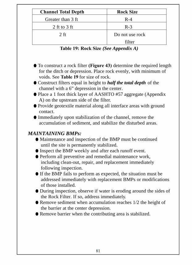
81
Channel Total Depth Rock Size
Greater than 3 ft R-4
2 ft to 3 ft R-3
2 ft Do not use rock
filter Table 19: Rock Size (See Appendix A)
● To construct a rock filter (Figure 43) determine the required length for the ditch or depression. Place rock evenly, with minimum of voids. See Table 19 for size of rock.
● Construct filters equal in height to half the total depth of the channel with a 6” depression in the center.
● Place a 1 foot thick layer of AASHTO #57 aggregate (Appendix A) on the upstream side of the filter.
● Provide geotextile material along all interface areas with ground contact.
● Immediately upon stabilization of the channel, remove the accumulation of sediment, and stabilize the disturbed areas.
MAINTAINING BMPs: ● Maintenance and inspection of the BMP must be continued
until the site is permanently stabilized. ● Inspect the BMP weekly and after each runoff event. ● Perform all preventive and remedial maintenance work,
including clean-out, repair, and replacement immediately following inspection.
● If the BMP fails to perform as expected, the situation must be addressed immediately with replacement BMPs or modifications of those installed.
● During inspection, observe if water is eroding around the sides of the Rock Filter. If so, address immediately.
● Remove sediment when accumulation reaches 1/2 the height of the barrier at the center depression.
● Remove barrier when the contributing area is stabilized.

82
Alternative BMPs: None Companion BMPs: None
DEFINITION: A non-woven, geotextile fabric bag that is used to filter sediment from sediment-laden water.
PURPOSE: Filter Bags are used to filter water pumped from disturbed areas prior to discharging over grassy areas or to Waters of the Commonwealth. They can also be used to filter water pumped from the sediment storage areas of sediment basins or traps. APPLICATION, METHODS, AND PROCEDURES:
● Filter bags should be made from non-woven geotextile material sewn with high strength, double stitched "J" type seams.
● Bags shall be located in well-vegetated (grassy) area, and discharge onto stable, erosion resistant areas. Where this is not possible, a geotextile underlayment and flow path shall be provided. Bags may be placed on filter stone to increase discharge capacity.
● Inspect area to determine the path discharge water will take.
● Stabilize any potentially erodible areas (steep slopes). ● Discharge should be distributed as sheet flow over a well
vegetated area. ● Construct a level platform using coarse aggregate. Place
sediment filter bags on the level platform. Bags shall not be placed on slopes greater than 5%.
● Use pump with a rating in gallons per minute not to exceed 50 percent of the maximum flow rate listed on the bag label. Double clamp the pump discharge hose firmly to the bag’s sewn-in spout.
● A suitable means of accessing the bag with machinery for removal and disposal of the bag should be provided.
PUMPED WATER FILTER BAG ES.13.FBAG
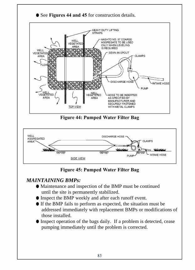
83
● See Figures 44 and 45 for construction details.
Figure 44: Pumped Water Filter Bag
Figure 45: Pumped Water Filter Bag
MAINTAINING BMPs: ● Maintenance and inspection of the BMP must be continued
until the site is permanently stabilized. ● Inspect the BMP weekly and after each runoff event. ● If the BMP fails to perform as expected, the situation must be
addressed immediately with replacement BMPs or modifications of those installed.
● Inspect operation of the bags daily. If a problem is detected, cease pumping immediately until the problem is corrected.

84
● Filter bags shall be replaced when they become ½ full of sediment. Keep spare bags available for replacement. Bags shall be placed on straps to facilitate removal unless bags come with lifting straps already attached.
● Before removing a bag from the hose, the bag should be tied off below the end of the hose, allowing the bag to drain. Do not allow the bag to drain through the inlet hole.
● Filter bags should be taken to an approved disposal area after use. ● Restore the site by cleaning and leaving it in a well-drained
and smoothly graded condition, blending into the existing topography. Permanently stabilize the area.

85
Alternative BMPs: None Companion BMPs: ST.9.GEOT
DEFINITION: Rock and geotextile placed at the entrance to construction sites.
PURPOSE: Rock Construction Entrances (RCE’s) should be installed wherever it is anticipated that construction traffic will exit the project site onto any roadway, public or private. Access to the site should be limited to stabilized construction entrance(s). APPLICATION, METHODS, AND PROCEDURES:
● It may be necessary to extend the length or width of a RCE to ensure effectiveness of the entrance.
● A geotextile underlayment should be placed over the existing ground prior to placing the stone.
● Construct a mountable berm only when 6” min cover cannot be provided over the pipe.
● Remove topsoil prior to installation of the entrance. ● See Figure 46 & 47 for construction details.
Figure 46: Rock Construction Entrance
ROCK CONSTRUCTION ENTRANCE ES.14.RCE
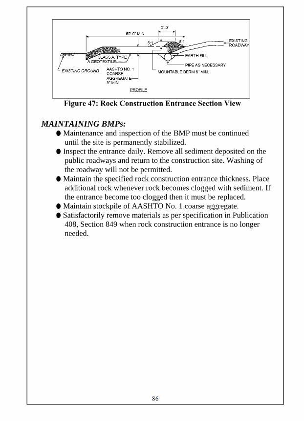
86
Figure 47: Rock Construction Entrance Section View
MAINTAINING BMPs:
● Maintenance and inspection of the BMP must be continued until the site is permanently stabilized.
● Inspect the entrance daily. Remove all sediment deposited on the public roadways and return to the construction site. Washing of the roadway will not be permitted.
● Maintain the specified rock construction entrance thickness. Place additional rock whenever rock becomes clogged with sediment. If the entrance become too clogged then it must be replaced.
● Maintain stockpile of AASHTO No. 1 coarse aggregate. ● Satisfactorily remove materials as per specification in Publication
408, Section 849 when rock construction entrance is no longer needed.

87
Alternative BMPs: ES.1.STRW, ES.2.SILT, ES.3.HEVY Companion BMPs: None
DEFINITION: Compost Filter Socks are a biodegradable mesh tube filled with compost filter material that meets certain performance criteria..
PURPOSE: Compost Filter Socks are used to control sheet flow runoff from disturbed areas where the discharge is to a stable area. APPLICATION, METHODS, AND PROCEDURES:
● Compost Filter Socks are especially useful on steep slopes. ● May be filled in place or prior to moving to the site. ● The flat dimension of the sock should be at least 1.5 times the
nominal diameter. Also, some settlement of the tube typically occurs after installation.
● Place compost filter sock on existing level grade. Extend both ends of the sock at least 8’-0” upslope at 45 degrees to the main alignment.
● Socks placed on earthen slopes should be anchored with stakes driven through the center of the sock or immediately downslope of the sock.
● Traffic shall not be permitted to cross filter socks. ● See Figure 48 for construction details.
Figure 48: Compost Filter Sock
COMPOST FILTER SOCK ES.15.CFS
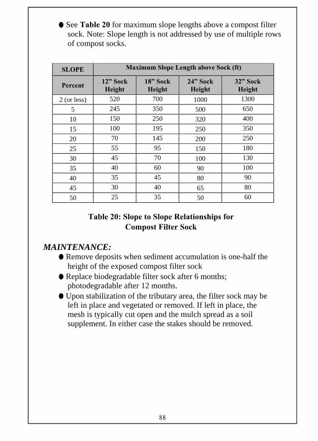
88
● See Table 20 for maximum slope lengths above a compost filter sock. Note: Slope length is not addressed by use of multiple rows of compost socks.
Table 20: Slope to Slope Relationships for Compost Filter Sock
MAINTENANCE:
● Remove deposits when sediment accumulation is one-half the height of the exposed compost filter sock
● Replace biodegradable filter sock after 6 months; photodegradable after 12 months.
● Upon stabilization of the tributary area, the filter sock may be left in place and vegetated or removed. If left in place, the mesh is typically cut open and the mulch spread as a soil supplement. In either case the stakes should be removed.
SLOPE Maximum Slope Length above Sock (ft)
Percent 12” Sock Height
18” Sock Height
24” Sock Height
32” Sock Height
2 (or less) 520 700 1000 1300
5 245 350 500 650
10 150 250 320 400
15 100 195 250 350
20 70 145 200 250
25 55 95 150 180
30 45 70 100 130
35 40 60 90 100
40 35 45 80 90
45 30 40 65 80
50 25 35 50 60
89
Alternative BMPs: ES.1.STRW, ES.2.SILT, ES.3.HEVY, ES.15.CFS Companion BMPs: None
DEFINITION: Compost Filter Berms are rows of compost material used for site stabilization or sediment control.
PURPOSE: Compost Filter Berms are used to remove sediment from runoff that is in the form of sheet flow. APPLICATION, METHODS, AND PROCEDURES:
● Compost filter berms may be vegetated or unvegetated. Vegetated filter berms are usually left in place as a post-construction BMP.
● Compost Filter Berms are best used in locations of sheet flow and are not to be used in channels or other areas of concentrated flow.
● Compost Filter Berms may not be used to construct sediment traps or other impoundments.
● Berms shall be placed at existing level grade. Both ends of the berm shall be extended at least 8 feet upslope at 45 degrees to the main alignment.
● The maximum slope length above a compost filter berm shall not exceed that shown in ES.2.SILT for 18” high silt barrier fence.
● Tall grass shall be cut prior to installation to minimize potential for undercutting. Berm shall be netted or otherwise anchored after installation.
● See Figure 49 for construction details.
COMPOST FILTER BERM ES.16.CFB

90
Figure 49: Compost Filter Berm
MAINTENANCE: ● Remove deposits when sediment accumulation is one-third the
height of the exposed compost filter berm. ● Any section of compost filter berm which has been
undermined or topped shall be immediately replaced.

91
Alternative BMPs: None Companion BMPs: None
DEFINITION: A runoff collection area to captures and holds flow from concentrated flows on the project site.
PURPOSE: A sediment trap or basin allows sediment to settle out prior to be discharged to waters of the commonwealth. If a sediment trap or basin is proposed, the District Design Unit should be contacted for advice on how to proceed. APPLICATION, METHODS, AND PROCEDURES:
● Sediment basins may not be located within the drainage area of a sediment trap or another sediment basin. Sediment basins also may not be located within a live stream channel, or a wetland. The bottom elevation should not be located below the seasonal high water table, adjacent to wetlands, or perennial stream channels. Unanticipated springs and seeps intercepted during excavation should be safely conveyed around the basin to a suitable down gradient discharge point.
● Sediment Basins are often designed to remain in place after construction as post construction BMP’s. Modifications to the basins may be needed for this conversion.
● Sediment Traps are to be used when the flow to the trap is 5 acres or less. Sediment Basins are not restricted by the acres contributing to them however the provided capacity should be sized for the disturbed acreage draining to the basin.
● Stabilize interior and exterior slopes with seeding and soil supplements and mulch. See ST.6.ECB.
SEDIMENT TRAPS AND BASIN ES.17.STB
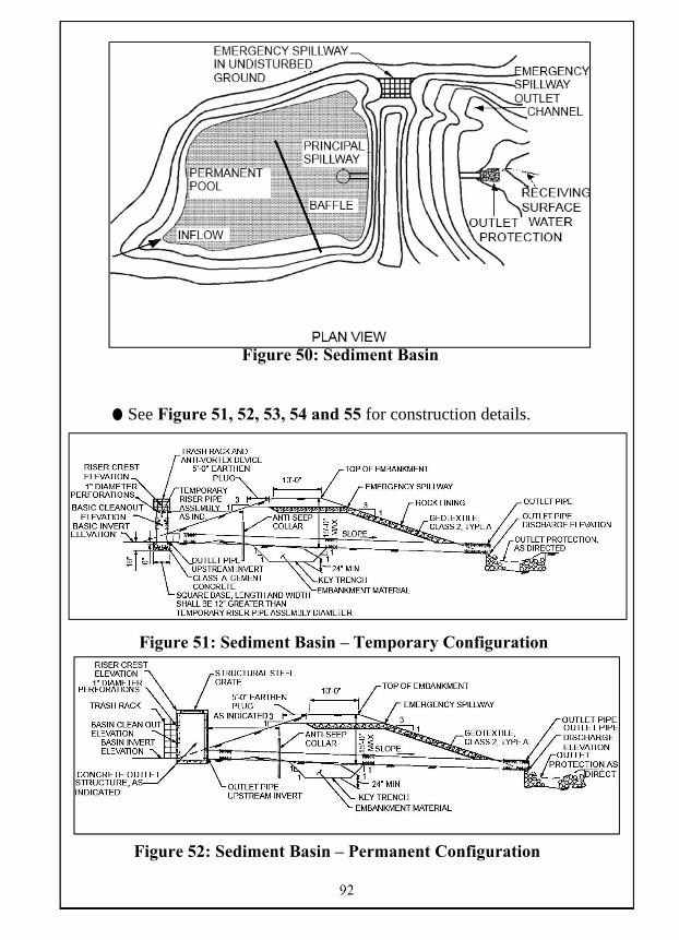
92
Figure 50: Sediment Basin
● See Figure 51, 52, 53, 54 and 55 for construction details.
Figure 51: Sediment Basin – Temporary Configuration
Figure 52: Sediment Basin – Permanent Configuration

93
Figure 53: Sediment Trap
Figure 54: Temporary Baffle Wall

94
Figure 55: Plywood Inlet Extension Detail MAINTENANCE:
● Place clean out stakes near the center of a sediment trap or basin. Remove sediment when the clean out elevations on the stake have been met. During removal, if required, remark clean out elevations on the stakes. Satisfactorily dispose of sediment.
● Stabilize interior and exterior slopes with seeding, soil supplements and mulch as indicated.
● Inspect the sediment trap or basin each week and after every storm event that produces runoff.
● Repair damaged or clogged spillways immediately. ● Remove all trash and other debris from sediment traps and
basins and spillways when directed. ● When directed, remove temporary sediment basins and sediment
traps or convert temporary sediment traps and basins to permanent stormwater management facilities.

95
Alternative BMPs: ES.17.STB Companion BMPs: ES.15.CFS
DEFINITION: Stacked compost filter socks used as a sediment trap.
PURPOSE: Compost sock sediment traps are often used near access roads where there is limited space for ESC control measures. They may also be used in other locations as sediment traps. APPLICATION, METHODS, AND PROCEDURES:
● Compost sock sediment traps shall not exceed 3 socks in height and shall be stacked in pyramidal form as noted in Figure 54. Minimum trap height is one 24” diameter sock. Additional storage may be provided by means of an excavated sump 12” deep extending 1-3 feet upslope of the socks along the lower side of the trap.
● Compost sock sediment traps are to be used when the drainage area to them is 5 acres or less.
● Installation of an excavated sump immediately above the socks may increase trap efficiency where soil conditions permit their construction.
● The ends of the trap shall be a minimum of 1 foot higher in elevation than the mid-section, which shall be located at the point of discharge.
● See Figure 56 for construction details.
COMPOST SOCK SEDIMENT TRAP ES.18.CSST
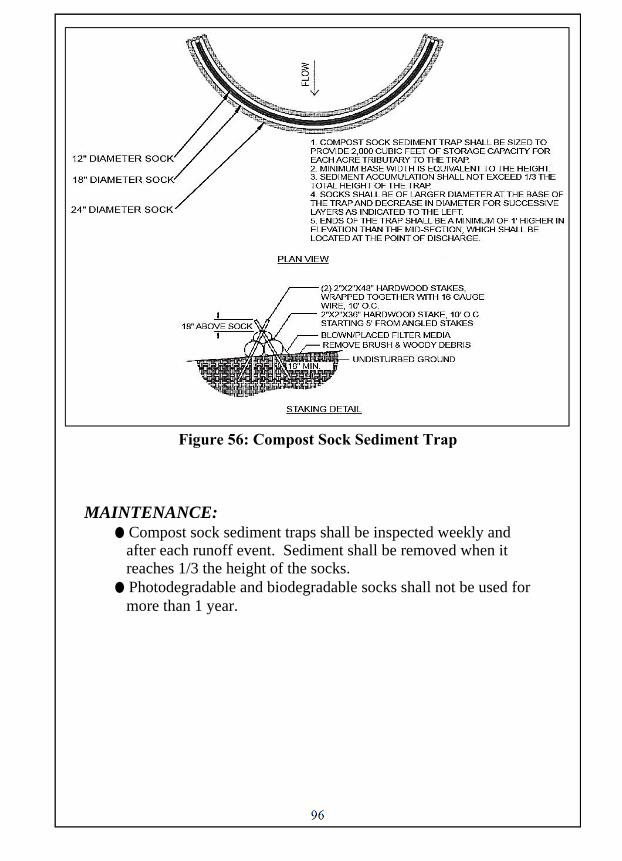
96
Figure 56: Compost Sock Sediment Trap MAINTENANCE:
● Compost sock sediment traps shall be inspected weekly and after each runoff event. Sediment shall be removed when it reaches 1/3 the height of the socks.
● Photodegradable and biodegradable socks shall not be used for more than 1 year.

97
Alternative BMPs: None Companion BMPs: ES.15.CFS
DEFINITION: An impervious membrane surrounded by compost filter socks or similar materials.
PURPOSE: Concrete washouts are used for the cleaning of chutes, mixers and hoppers of the delivery vehicle unless such a facility will be used at the source of the concrete. Under no circumstances may wash water from these vehicles be allowed to enter any surface waters. APPLICATION, METHODS, AND PROCEDURES:
● A suitable impervious geomembrane should be placed at the location of the washout.
● Compost socks should be stacked in the manner recommended by the manufacturer around the perimeter of the geomembrane so as to form a ring with the ends of the sock located at the upslope corner. Care should be taken to ensure continuous contact of the sock with the geomembrane at all locations. Where necessary, socks may be stacked and stakes so as to form a triangular cross-section.
● Washout facilities should not be placed within 50 feet of storm drains, open ditches or surface waters. They should be in a convenient location for trucks.
● Wherever possible, they should be on slopes not exceeding 2% grade.
● See Figure 57 for construction details.
CONCRETE WASHOUT ES.19.CWSH

98
Figure 57: Concrete Washout MAINTENANCE:
● Photodegradable and biodegradable socks shall not be used for more than 1 year.
● Inspect concrete wash outs daily. ● Damaged or leaking washouts should be deactivated and
repaired or replaced immediately. ● Accumulated materials should be removed when they reach
75% capacity. Plastic liners should be replaced with each cleaning of the washout facility.
● A suitable impervious geomembrane should be placed at the location of the washout.
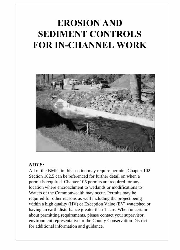
EROSION AND SEDIMENT CONTROLS
FOR IN-CHANNEL WORK
NOTE: All of the BMPs in this section may require permits. Chapter 102 Section 102.5 can be referenced for further detail on when a permit is required. Chapter 105 permits are required for any location where encroachment to wetlands or modifications to Waters of the Commonwealth may occur. Permits may be required for other reasons as well including the project being within a high quality (HV) or Exception Value (EV) watershed or having an earth disturbance greater than 1 acre. When uncertain about permitting requirements, please contact your supervisor, environment representative or the County Conservation District for additional information and guidance.

99
BYPASS CHANNEL WITH NON-EROSIVE LINING IC.1.BYPS
Alternative BMPs: IC.3.PUMP, IC.4.COFF Companion BMPs: ES.4.RFOT, ES.9.OUTL (Rock Energy Dissipator), ES.13.FBAG
DEFINITION: A temporary stream diversion using a channel to divert flow in the natural stream channel around the work area and back into the natural channel at a downstream location.
PURPOSE: When in-channel work is necessary, a bypass channel can be used to divert stream flow around the work area.
APPLICATION, METHODS, AND PROCEDURES: ● When work is necessary in a channel, it should be done during
the low flow season whenever practical. ● Temporary stream diversion channels should be stabilized
with at least a suitable geotextile lining before use. Refer to Section ST.9.GEOT for specifics.
● If the temporary bypass channel will be used for no more than 3 days, it will be designed to convey normal base flows. If it will be used for longer it should convey bank full flow (original channel). All such channels should be constructed from the downstream end upward.
● A Sandbag Diversion Dam or Cofferdam can be utilized to divert flow around the work area. See Figure 62.
● Construct and maintain rock filters in accordance with Section ES.12.RFIL.
● Energy dissipators can be constructed in accordance with Section ES.9.OUTL.
● The temporary bypass will be constructed as specified in the plans. See Figure 58 for typical layout.
BYPASS CHANNEL WITH NON-EROSIVE LINING IC.1.BYPS

100
Figure 58: Bypass Channel with Non-Erosive Lining
CONSTRUCTION: Temporary Dam shall be made of sandbags, Jersey Barriers, or other non-erosive material, no earth fill. For low gradient channels, the rock filter may be replaced by an impervious cofferdam to prevent backflow into the work area.
MAINTAINING BMPs: ● Maintenance and inspection of the BMP must be continued
until the site is permanently stabilized. ● Inspect the BMP weekly and after each runoff event. ● Perform all preventive and remedial maintenance work,
including clean-out, repair, replacement, regrading, reseeding, remulching, and rematting immediately following inspection.
● If the BMP fails to perform as expected, the situation must be addressed immediately with replacement BMPs or modifications of those installed.
● Ensure there are no channel blockages. ● Inspect the area where the flow is re-introduced into the natural
channel to ensure there is no erosion. ● Upon completion, the temporary channel must be removed and all
channel entrances restored, as much as possible.
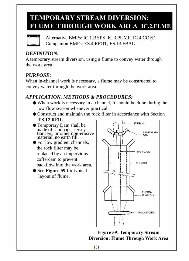
101
TEMPORARY STREAM DIVERSION: FLUME THROUGH WORK AREA IC.2.FLME
Alternative BMPs: IC.1.BYPS, IC.3.PUMP, IC.4.COFF Companion BMPs: ES.4.RFOT, ES.13.FBAG
DEFINITION: A temporary stream diversion, using a flume to convey water through the work area.
PURPOSE: When in-channel work is necessary, a flume may be constructed to convey water through the work area.
APPLICATION, METHODS & PROCEDURES: ● When work is necessary in a channel, it should be done during the
low flow season whenever practical. ● Construct and maintain the rock filter in accordance with Section
ES.12.RFIL. ● Temporary Dam shall be
made of sandbags, Jersey Barriers, or other non-erosive material, no earth fill.
● For low gradient channels, the rock filter may be replaced by an impervious cofferdam to prevent backflow into the work area.
● See Figure 59 for typical layout of flume.
Figure 59: Temporary Stream Diversion: Flume Through Work Area
TEMPORARY STREAM DIVERSION: FLUME THROUGH WORK AREA IC.2.FLME

102
MAINTAINING BMPs: ● Maintenance and inspection of the BMP must be continued until
the site is permanently stabilized. ● Inspect the BMP weekly and after each runoff event. ● Perform all preventive and remedial maintenance work,
including clean-out, repair, and replacement immediately following inspection.
● If the BMP fails to perform as expected, the situation must be addressed immediately with replacement BMPs or modifications of those installed.
● Inspect the area where the flow is re-introduced into the natural course to ensure there is no erosion.

103
TEMPORARY STREAM DIVERSION: PUMP AROUND IN-CHANNEL WORK AREA IC.3.PUMP
Alternative BMPs: IC.1.BYPS, IC.2.FLME, IC.4.COFF Companion BMPs: ES.4.RFOT, ES.13.FBAG
DEFINITION: A temporary stream diversion using a pump to divert runoff from the natural stream channel, through or around the work area, and discharge it downstream.
PURPOSE: When in-channel work is necessary, a pump bypass, in combination with cofferdams, can be used to move the base stream flow around the work area.
APPLICATION, METHODS, AND PROCEDURES: ● When work is necessary in a channel, it should be done during
the low flow season whenever practical. ● Construct and maintain the rock filter in accordance with
Section ES.12.RFIL. ● An energy dissipator should be constructed where the flow is
re-introduced to the natural channel. ● Size of pump should be selected to accommodate
anticipated stream flow. ● Pump intake shall be maintained a sufficient distance from
the bottom to prevent sediment from entering the system. ● See Figure 60 for typical layout of pump bypass. ● When a pumped water filter bag is utilized then section ES.13 FBAG
shall be followed.
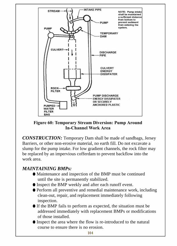
104
Figure 60: Temporary Stream Diversion: Pump Around
In-Channel Work Area
CONSTRUCTION: Temporary Dam shall be made of sandbags, Jersey Barriers, or other non-erosive material, no earth fill. Do not excavate a slump for the pump intake. For low gradient channels, the rock filter may be replaced by an impervious cofferdam to prevent backflow into the work area.
MAINTAINING BMPs: ● Maintenance and inspection of the BMP must be continued
until the site is permanently stabilized. ● Inspect the BMP weekly and after each runoff event. ● Perform all preventive and remedial maintenance work, including
clean-out, repair, and replacement immediately following inspection.
● If the BMP fails to perform as expected, the situation must be addressed immediately with replacement BMPs or modifications of those installed.
● Inspect the area where the flow is re-introduced to the natural course to ensure there is no erosion.

105
IN-STREAM COFFERDAM DIVERSION IC.4.COFF
Alternative BMPs: IC.1.BYPS Companion BMPs: ES.13.FBAG
DEFINITION: A dam constructed in a channel to keep flow away from an in-channel work area.
PURPOSE: When in-channel work is necessary, an in-stream cofferdam can be constructed to keep flow away from that area.
APPLICATION, METHODS AND PROCEDURES: ● When work is necessary in a channel, it should be done during
the low flow season whenever practical. ● See Figure 61 for typical layout. Temporary Cofferdam shall be
constructed of sandbags, Jersey Barriers or other non-erosive material, no earth fill.
● A pump may be needed when a cofferdam is in place. Water should be pumped from the work are to filter bag as needed when setting up a cofferdam around an abutment, embankment, or repair.
IN-STREAM COFFERDAM DIVERSION IC.4.COFF

106
Figure 61: In-Stream Cofferdam Diversion
Figure 62: Sandbag Diversion Dam or Cofferdam
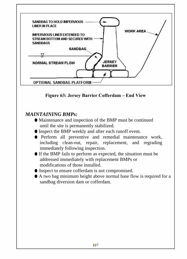
107
Figure 63: Jersey Barrier Cofferdam – End View
MAINTAINING BMPs:
● Maintenance and inspection of the BMP must be continued until the site is permanently stabilized.
● Inspect the BMP weekly and after each runoff event. ● Perform all preventive and remedial maintenance work,
including clean-out, repair, replacement, and regrading immediately following inspection.
● If the BMP fails to perform as expected, the situation must be addressed immediately with replacement BMPs or modifications of those installed.
● Inspect to ensure cofferdam is not compromised. ● A two bag minimum height above normal base flow is required for a
sandbag diversion dam or cofferdam.

APPENDIX A

108
Percent Passing (Square Openings) Class, Size No. (NCSA) R-8•• R-7•• R-6 R-5 R-4 R-3
Rock Size, Inches
42 100* 30 100* 24 15-50 100* 18 15-50 100*
15 0-15 12 0-15 15-50 100*
9 15-50
6 0-15 15-50 100*
4 0-15
3 0-15 15-50
2 0-15
Nominal Placement Thickness, inches
48 36 30
24 18 12
Rock Size
* Maximum Allowable Rock Size.
* * Use Class 2, Type A Geotextile
Acceptance of gradation will be based upon visual inspection and certification. Provide two samples of rock, at least 5 tons each or each one-half the total project quantity, whichever is smaller. Provide one sample in place at the construction site and provide the other sample at the quarry. The construction site sample may be incorporated in the work. These samples will be used as a reference for judging the size and gradation of the rock supplied and placed. Certify as to gradation, as specified in Section 106.03(b)3.
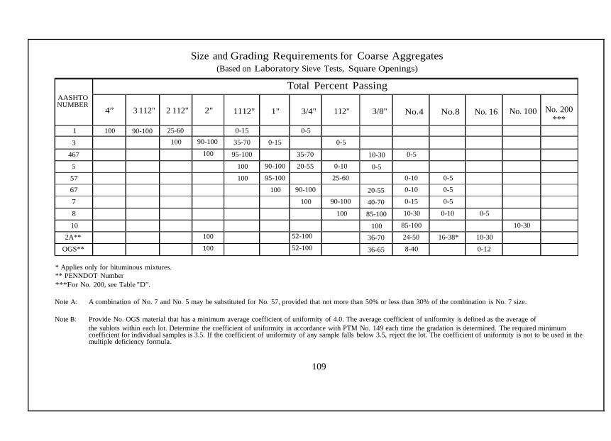
109
AASHTO NUMBER
Total Percent Passing
4”
3 112"
2 112"
2"
1112"
1"
3/4"
112"
3/8"
No.4
No.8
No. 16
No. 100
No. 200
*** 1 100 90-100 25-60 0-15 0-5 3 100 90-100 35-70 0-15 0-5
467 100 95-100 35-70 10-30 0-5
5 100 90-100 20-55 0-10 0-5 57 100 95-100 25-60 0-10 0-5
67 100 90-100 20-55 0-10 0-5
7 100 90-100 40-70 0-15 0-5
8 100 85-100 10-30 0-10 0-5
10 100 85-100 10-30
2A** 100 52-100 36-70 24-50 16-38* 10-30
OGS** 100 52-100 36-65 8-40 0-12
Size and Grading Requirements for Coarse Aggregates (Based on Laboratory Sieve Tests, Square Openings)
* Applies only for bituminous mixtures. ** PENNDOT Number ***For No. 200, see Table "D".
Note A: A combination of No. 7 and No. 5 may be substituted for No. 57, provided that not more than 50% or less than 30% of the combination is No. 7 size.
Note B: Provide No. OGS material that has a minimum average coefficient of uniformity of 4.0. The average coefficient of uniformity is defined as the average of the sublots within each lot. Determine the coefficient of uniformity in accordance with PTM No. 149 each time the gradation is determined. The required minimum coefficient for individual samples is 3.5. If the coefficient of uniformity of any sample falls below 3.5, reject the lot. The coefficient of uniformity is not to be used in the multiple deficiency formula.

APPENDIX B

110
CONTACT INFORMATION
DEP REGIONAL OFFICES
Southeast Region - Norristown Northeast Region - Wilkes-Barre Southcentral Region - Harrisburg Northcentral Region - Williamsport Southwest Region - Pittsburgh Northwest Region - Meadville
(484) 250-5900 (570) 826-2511 (717) 705-4700 (570) 327-3636 (412) 442-4000 (814) 332-6945
US ARMY CORPS OF ENGINEERS
Baltimore District Public Affairs City Crescent Building 10 South Howard Street Baltimore, MD 21201 (800) 434-0988 Huntingdon District U.S. Army Corps of Engineers 502 Eighth Street Huntington, WV 25701-2070 (866) 502-2570

111
COUNTY CONSERVATION DISTRICTS
Adams Conservation District Allegheny Conservation District Armstrong Conservation District Beaver Conservation District Bedford Conservation District Berks Conservation District Blair Conservation District Bradford Conservation District Bucks Conservation District Butler Conservation District Cambria Conservation District Cameron Conservation District Carbon Conservation District Centre Conservation District Chester Conservation District Clarion Conservation District Clearfield Conservation District Clinton Conservation District Columbia Conservation District Crawford Conservation District Cumberland Conservation District Dauphin Conservation District Delaware Conservation District Elk Conservation District Erie Conservation District Fayette Conservation District Forest Conservation District Franklin Conservation District Fulton Conservation District Greene Conservation District Huntingdon Conservation District Indiana Conservation District Jefferson Conservation District Juniata Conservation District Lackawanna Conservation District Lancaster Conservation District
(717) 334-0636 (412) 241-7645 (724) 548-3425 (724) 378-1701 (814) 623-7900 ext. 4 (610) 372-4657 (814) 696-0877 ext. 5 (570) 265-5539 (215) 345-7577 (724) 284-5270 (814) 472-2120 (814) 486-2244 ext. 5 (610) 377-4894 ext. 4 (814) 355-6817 (610) 925-4920 (814) 297-7813 (814) 765-2629 (570) 726-3798 (570) 784-1310 (814) 763-5269 (717) 240-7812 (717) 921-8100 (610) 892-9484 (814) 776-5373 (814) 825-6403 (724) 438-4497 (814) 755-3450 (717) 264-5499 (717) 485-3547 (724) 852-5278 (814) 627-1627 (724) 471-4751 (814) 849-7463 (717) 436-8953 ext. 5 (570) 382-3086 (717) 299-5361

112
COUNTY CONSERVATION DISTRICTS
Lawrence Conservation District Lebanon Conservation District Lehigh Conservation District Luzerne Conservation District Lycoming Conservation District McKean Conservation District Mercer Conservation District Mifflin Conservation District Monroe Conservation District Montgomery Conservation District Montour Conservation District Northampton Conservation District Northumberland Conservation District Perry Conservation District Pike Conservation District Potter Conservation District Schuylkill Conservation District Snyder Conservation District Somerset Conservation District Sullivan Conservation District Susquehanna Conservation District Tioga Conservation District Union Conservation District Venango Conservation District Warren Conservation District Washington Conservation District Wayne Conservation District Westmoreland Conservation District Wyoming Conservation District York Conservation District
(724) 652-4512 (717) 272-3908 ext. 4 (610) 391-9583 (570) 674-7991 (570) 433-3003 (814) 887-4001 (724) 662-2242 (717) 248-4695 (570) 629-3060 (610) 489-4506 (570) 271-1140 (610) 746-1971 (570) 495-4665 (717) 582-8988 ext. 4 (570) 226-8220 (814) 274-8411 ext. 4 (570) 622-3742 ext. 5 (570) 837-3000 (814) 445-4652 ext. 5 (570) 928-7057 (570) 278-4600 ext. 280 (570) 724-1801 ext. 5 (570) 524-3860 (814) 676-2832 (814) 726-1441 (724) 705-7098 (570) 253-0930 (724) 837-5271 (570) 836-2589 (717) 840-7430