pdi+ layout
TRANSCRIPT
7/26/2019 pdi+ layout
http://slidepdf.com/reader/full/pdi-layout 1/104
C o m p T I A P D I +
C e r t i f i c a t i o n
Instructor’s Edition
NOT FOR PRINTING OR INSTRUCTIONAL USE

7/26/2019 pdi+ layout
http://slidepdf.com/reader/full/pdi-layout 2/104
CompTIA PDI+ Certification
Series Product Managers: Charles G. Blum and Adam A. Wilcox
Developmental Editor: Andy LaPageTechnical Editor: Kenneth Wilkinson
Copyeditor: Ken Maher
Keytester: Gail Sandler
Series Designer: Adam A. Wilcox
Photographs provided as a courtesy of Ricoh Americas Corporation
COPYRIGHT © 2008 Axzo Press. All rights reserved.
No part of this work may be reproduced, transcribed, or used in any form or by any means ⎯ graphic, electronic, or
mechanical, including photocopying, recording, taping, Web distribution, or information storage and retrievalsystems ⎯ without the prior written permission of the publisher.
For more information, go to www.axzopress.com.
Trademarks
ILT Series is a trademark of Axzo Press.
Some of the product names and company names used in this book have been used for identification purposes only and
may be trademarks or registered trademarks of their respective manufacturers and sellers.
Disclaimers
We reserve the right to revise this publication and make changes from time to time in its content without notice.
The logo of the CompTIA Authorized Quality Curriculum (CAQC) program and the status of this or other trainingmaterial as “Authorized” under the CompTIA Authorized Quality Curriculum program signifies that, in CompTIA’s
opinion, such training material covers the content of CompTIA’s related certification exam.
The contents of this training material were created for the CompTIA PDI+ exam covering CompTIA certification
objectives that were current as of December 2007.
CompTIA has not reviewed or approved the accuracy of the contents of this training material and specificallydisclaims any warranties of merchantability or fitness for a particular purpose. CompTIA makes no guaranteeconcerning the success of persons using any such “Authorized” or other training material in order to prepare for any
CompTIA certification exam.
ISBN 10: 1-4260-9995-9
ISBN 13: 978-1-4260-9995-3
Printed in the United States of America
1 2 3 4 5 GL 06 05 04 03
NOT FOR PRINTING OR INSTRUCTIONAL USE

7/26/2019 pdi+ layout
http://slidepdf.com/reader/full/pdi-layout 3/104
C o n t e n t s
Introduction iii
Topic A: About the manual............................................................................... iv Topic B: Setting student expectations .............................................................. ix Topic C: Classroom setup................................................................................ xiii Topic D: Support.............................................................................................. xix
Electromechanical components 1-1 Topic A: Electromechanical components ........................................................ 1-2 Topic B: Mechanical components .................................................................. 1-14 Topic C: Electrical components...................................................................... 1-21 Unit summary: Electromechanical components.............................................. 1-34
Printing and scanning 2-1
Topic A: Printing ............................................................................................. 2-2 Topic B: Scanning ..........................................................................................2-33 Unit summary: Printing and scanning............................................................. 2-40
Connectivity 3-1 Topic A: Local printing and scanning.............................................................. 3-2 Topic B: Network printing and scanning........................................................ 3-22 Unit summary: Connectivity ........................................................................... 3-47
Maintenance and troubleshooting 4-1 Topic A: Maintenance...................................................................................... 4-2 Topic B: Troubleshooting................................................................................ 4-8
Unit summary: Maintenance and troubleshooting .......................................... 4-30
Professional conduct 5-1 Topic A: Communication ................................................................................5-2 Topic B: Safety ............................................................................................... 5-16 Unit summary: Professional conduct ..............................................................5-27
Certification exam objectives map A-1 Topic A: Comprehensive exam objectives ......................................................A-2
Course summary S-1 Topic A: Course summary ............................................................................... S-2
Topic B: Continued learning after class ..........................................................S-3
Glossary G-1
Index I-1
NOT FOR PRINTING OR INSTRUCTIONAL USE

7/26/2019 pdi+ layout
http://slidepdf.com/reader/full/pdi-layout 4/104
ii CompTIA PDI+ Certification
NOT FOR PRINTING OR INSTRUCTIONAL USE

7/26/2019 pdi+ layout
http://slidepdf.com/reader/full/pdi-layout 5/104
iii
Introduction
After reading this introduction, you’ll know
how to:
A Use ILT Series manuals in general.
B Use prerequisites, a target student
description, course objectives, and a skills
inventory to set student expectations properly for the course.
C Set up a classroom to teach this course.
D Get support for setting up and teaching this
course.
NOT FOR PRINTING OR INSTRUCTIONAL USE

7/26/2019 pdi+ layout
http://slidepdf.com/reader/full/pdi-layout 6/104
iv CompTIA PDI+ Certification
Topic A: About the manual
ILT Series philosophy
Our goal is to make you, the instructor, as successful as possible. To that end, our
manuals facilitate student learning by providing structured interaction with the softwareitself. While we provide text to help you explain difficult concepts, the hands-on
activities are the focus of our courses. Leading the students through these activities will
teach the skills and concepts effectively.
We believe strongly in the instructor-led class. For many students, having a thinking,
feeling instructor in front of them is always the most comfortable way to learn. Because
the students’ focus should be on you, our manuals are designed and written to facilitate
your interaction with the students and not to call attention to manuals themselves.
We believe in the basic approach of setting expectations, then teaching, and providing
summary and review afterwards. For this reason, lessons begin with objectives and end
with summaries. We also provide overall course objectives and a course summary to
provide both an introduction to and closure on the entire course.Our goal is your success. We encourage your feedback in helping us to improve our
manuals continually to meet your needs.
Manual components
The manuals contain these major components:
• Table of contents
• Introduction
• Units
• Appendix
• Course summary
• Quick reference
• Glossary
• Index
Each element is described below.
Table of contents
The table of contents acts as a learning roadmap for you and the students.
Introduction
The introduction contains information about our training philosophy and our manual
components, features, and conventions. It contains target student, prerequisite,
objective, and setup information for the specific course. Finally, the introduction
contains support information.
NOT FOR PRINTING OR INSTRUCTIONAL USE

7/26/2019 pdi+ layout
http://slidepdf.com/reader/full/pdi-layout 7/104
Introduction v
Units
Units are the largest structural component of the actual course content. A unit begins
with a title page that lists objectives for each major subdivision, or topic, within the unit
Within each topic, conceptual and explanatory information alternates with hands-on
activities. Units conclude with a summary comprising one paragraph for each topic, and
an independent practice activity that gives students an opportunity to practice the skills
they’ve learned.The conceptual information takes the form of text paragraphs, exhibits, lists, and tables.
The activities are structured in two columns, one telling students what to do, the other
providing explanations, descriptions, and graphics. Throughout a unit, instructor notes
are found in the left margin.
Appendices
Appendix A lists all CompTIA PDI+ exam objectives along with references to
corresponding coverage in this manual.
Course summary
This section provides a text summary of the entire course. It’s useful for providingclosure at the end of the course. The course summary also indicates the next course in
this series, if there is one, and lists additional resources students might find useful as
they continue to learn about the software.
Quick reference
The quick reference is an at-a-glance job aid summarizing some of the more common
features of the software.
Glossary
The glossary provides definitions for all of the key terms used in this course.
Index
The index at the end of this manual makes it easy for you and your students to find
information about a particular software component, feature, or concept.
NOT FOR PRINTING OR INSTRUCTIONAL USE

7/26/2019 pdi+ layout
http://slidepdf.com/reader/full/pdi-layout 8/104
vi CompTIA PDI+ Certification
Manual conventions
We’ve tried to keep the number of elements and the types of formatting to a minimum
in the manuals. We think this approach aids in clarity and makes the manuals moreelegant looking. But there are some conventions and icons you should know about.
Item DescriptionInstructor note/icon
Italic text In conceptual text, indicates a new term or feature.
Bold text In unit summaries, indicates a key term or concept. In
an independent practice activity, indicates an explicit
item that you select, choose, or type.
Code font Indicates code or syntax.
Longer strings of
code will look
like this.
In the hands-on activities, any code that’s too long to fit
on a single line is divided into segments by one or more
continuation characters (). This code should be
entered as a continuous string of text.
Instructor notes. In the left margin, provide tips, hints, and warnings for
the instructor.
Select bold item In the left column of hands-on activities, bold sans-serif
text indicates an explicit item that you select, choose,
or type.
Keycaps likee Indicate a key on the keyboard you must press.
Warning icon.Warnings prepare instructors for potential classroom
management problems.
Tip icon.Tips give extra information the instructor can share
with students.
Setup icon.Setup notes provide a realistic business context for
instructors to share with students, or indicate additional
setup steps required for the current activity.
Projector icon.Projector notes indicate that there is a PowerPoint slide
for the adjacent content.
NOT FOR PRINTING OR INSTRUCTIONAL USE

7/26/2019 pdi+ layout
http://slidepdf.com/reader/full/pdi-layout 9/104
Introduction vii
Hands-on activities
The hands-on activities are the most important parts of our manuals. They’re divided
into two primary columns. The “Here’s how” column gives short directions to thestudents. The “Here’s why” column provides explanations, graphics, and clarifications.
To the left, instructor notes provide tips, warnings, setups, and other information for the
instructor only. Here’s a sample:
Do it! A-1: Creating a commission formula
Here’s how Here’s why
1 Open Sales This is an oversimplified sales compensation
worksheet. It shows sales totals, commissions,and incentives for five sales reps.
Take the time to makesure your studentsunderstand thisworksheet. We’ll be here awhile.
2 Observe the contents of cell F4
The commission rate formulas use the name“C_Rate” instead of a value for the commission
rate.
For these activities, we’ve provided a collection of data files designed to help students
learn each skill in a real-world business context. As students work through the activities
they modify and update these files. Of course, students might make a mistake and
therefore want to re-key the activity starting from scratch. To make it easy to start over,
students rename each data file at the end of the first activity in which the file is
modified. Our convention for renaming files is to add the word “My” to the beginning
of the file name. In the above activity, for example, students are using a file called
“Sales” for the first time. At the end of this activity, they would save the file as “My
sales,” thus leaving the “Sales” file unchanged. If students make mistakes, they can start
over using the original “Sales” file.In some activities, however, it might not be practical to rename the data file. Such
exceptions are indicated with an instructor note. If students want to retry one of these
activities, you need to provide a fresh copy of the original data file.
NOT FOR PRINTING OR INSTRUCTIONAL USE

7/26/2019 pdi+ layout
http://slidepdf.com/reader/full/pdi-layout 10/104
viii CompTIA PDI+ Certification
PowerPoint presentations
Each unit in this course has an accompanying PowerPoint presentation. These slide
shows are designed to support your classroom instruction while providing students witha visual focus. Each presentation begins with a list of unit objectives and ends with a
unit summary slide. We strongly recommend that you run these presentations from the
instructor’s station as you teach this course. A copy of PowerPoint Viewer is included,
so it isn’t necessary to have PowerPoint installed on your computer.
The ILT Series PowerPoint add-in
The CD also contains a PowerPoint add-in that enables you to do two things:
• Create slide notes for the class
• Display a control panel for the Flash movies embedded in the presentations
To load the PowerPoint add-in:
1 Copy the Course_ILT.ppa file to a convenient location on your hard drive.
2 Start PowerPoint.
3 Choose Tools, Macro, Security to open the Security dialog box. On the Security
Level tab, select Medium (if necessary), and then click OK.
4 Choose Tools, Add-Ins to open the Add-Ins dialog box. Then, click Add New.
5 Browse to and double-click the Course_ILT.ppa file, and then click OK. A
message box will appear, warning you that macros can contain viruses.
6 Click Enable Macros. The Course_ILT add-in should now appear in the
Available Add-Ins list (in the Add-Ins dialog box). The “x” in front of
Course_ILT indicates that the add-in is loaded.
7 Click Close to close the Add-Ins dialog box.
After you complete this procedure, a new toolbar is available at the top of the
PowerPoint window. This toolbar contains a single button labeled “Create SlideNotes.”
Click this button to generate slide-notes files in both text (.txt) and Excel (.xls) format.
By default, these files are saved to the folder that contains the presentation. If the
PowerPoint file is on a CD-ROM or in some other location to which the slide-notes files
can’t be saved, you’ll be prompted to save the presentation to your hard drive and try
again.
When you run a presentation and come to a slide that contains a Flash movie, you see a
small control panel in the lower-left corner of the screen. You can use this panel to start,
stop, and rewind the movie, or to play it again.
NOT FOR PRINTING OR INSTRUCTIONAL USE

7/26/2019 pdi+ layout
http://slidepdf.com/reader/full/pdi-layout 11/104
Introduction ix
Topic B: Setting student expectations
Properly setting student expectations is essential to your success. This topic will help
you do that by providing:
• Prerequisites for this course
• A description of the target student• A list of the objectives for the course
• A skills assessment for the course
Course prerequisites
Students taking this course should be familiar with personal computers and the use of a
keyboard and a mouse. Furthermore, this course assumes that students have user-level
experience using Windows XP.
Target student
Students taking this course are entry-level support technicians who want to pass the
CompTIA PDI+ exam. In addition, these students plan to support digital print and
document-imaging devices in the workplace. Target students might also include current
computer support personnel who want to learn more about printers and imaging devices
to advance in their current positions.
How to become CompTIA certified
In order to achieve CompTIA PDI+ certification, a student must register for and pass
the CompTIA PDI+ exam. In order to become CompTIA certified, students must:
1 Select a certification exam provider. For more information, students should visit
http://certification.comptia.org/resources/registration.aspx2 Register for and schedule a time to take the CompTIA certification exam(s) at a
convenient location.
3 Read and sign the Candidate Agreement, which will be presented at the time of
the exam. The complete text of the Candidate Agreement can be found at:
http://certification.comptia.org/resources/canidate_agreement.aspx
4 Take and pass the CompTIA certification exam(s).
For more information about CompTIA’s certifications, such as its industry acceptance,
benefits or program news, students should visit http://certification.comptia.org.
CompTIA is a not-for-profit information technology (IT) trade association. CompTIA’s
certifications are designed by subject matter experts from across the IT industry. Each
CompTIA certification is vendor-neutral, covers multiple technologies and requiresdemonstration of skills and knowledge widely sought after by the IT industry.
To contact CompTIA with any questions or comments, please call (630) 678-8300 or
e-mail [email protected].
NOT FOR PRINTING OR INSTRUCTIONAL USE

7/26/2019 pdi+ layout
http://slidepdf.com/reader/full/pdi-layout 12/104
x CompTIA PDI+ Certification
Course objectives
You should share these overall course objectives with your students at the beginning of
the day. Doing this gives the students an idea about what to expect, and it helps youidentify students who might be misplaced. Students are considered misplaced when they
lack the prerequisite knowledge or when they already know most of the subject matter
to be covered.
Note: In addition to the general objectives listed below, specific CompTIA PDI+ exam
objectives are listed at the beginning of each topic. For a complete mapping of exam
objectives to course content, see Appendix A.
After completing this course, students will know how to:
• Identify and explain the function of electromechanical, mechanical, and
electrical components.
• Identify and describe the components and processes involved in printing and
scanning.
• Connect printers and scanners to a computer, and connect to and use networked
printing and imaging devices.
• Troubleshoot printer and scanner problems.
• Communicate effectively with customers and maintain a safe environment.
NOT FOR PRINTING OR INSTRUCTIONAL USE

7/26/2019 pdi+ layout
http://slidepdf.com/reader/full/pdi-layout 13/104
Introduction xi
Skills inventory
Use the following form to gauge students’ skill levels entering the class (students have
copies in the introductions of their student manuals). For each skill listed, have studentsrate their familiarity from 1 to 5, with five being the most familiar. Emphasize that this
isn’t a test. Rather, it’s intended to provide students with an idea of where they’re
starting from at the beginning of class. If a student is wholly unfamiliar with all the
skills, he or she might not be ready for the class. A student who seems to understand allof the skills, on the other hand, might need to move on to the next course in the series.
Skill 1 2 3 4 5
Examining the characteristics of electricity
Considering electrical safety
Identifying electrical components
Identifying mechanical components
Measuring electrical values
Identifying electrical components
Examining the Windows printing process
Discussing color theory
Examining the inkjet print process
Examining the EP print process
Examining print media
Examining the scan process
Connecting a serial cable
Connecting a parallel cable
Connecting a USB cable
Connecting an IEEE 1394 cable
Installing an inkjet printer
Installing a laser printer
Installing a scanner
Connecting to the network
Viewing installed network components
Using wireless communications technologies
NOT FOR PRINTING OR INSTRUCTIONAL USE

7/26/2019 pdi+ layout
http://slidepdf.com/reader/full/pdi-layout 14/104
xii CompTIA PDI+ Certification
Skill 1 2 3 4 5
Connecting to a shared printer
Using ipconfig to display TCP/IP settings
Testing TCP/IP connectivity
Using nslookup to verify settings
Identifying network scanning basics
Performing inkjet and EP printer maintenance
Performing scanner maintenance
Troubleshooting problems
Using Microsoft Knowledge Base to research a problem
Tracking problems and resolutions
Troubleshooting printer problems
Troubleshooting scanner and multifunction device problems
Using effective verbal communication
Using non-verbal communication effectively
Maintaining professionalism
Ensuring customer satisfaction
Identifying typical off and computer-related hazards
Reading a material safety data sheet
Selecting the proper methods for equipment disposal
NOT FOR PRINTING OR INSTRUCTIONAL USE

7/26/2019 pdi+ layout
http://slidepdf.com/reader/full/pdi-layout 15/104
Introduction xiii
Topic C: Classroom setup
All our courses assume that each student has a personal computer to use during the
class. Our hands-on approach to learning requires that they do. This topic gives
information on how to set up the classroom to teach this course. It includes minimumrequirements for the students’ personal computers, setup information for the first time
you teach the class, and setup information for each time that you teach after the first
time you set up the classroom.
Hardware requirements
Each student’s personal computer should have:
• Intel Pentium II or Intel-compatible processor, running at 400 MHz or higher
(Pentium III strongly recommended)
• At least 512 MB RAM
• SVGA display adapter, supporting at least 256 colors and 800×600 resolution
• Keyboard and mouse
• 10/100 Mbps network card (NIC), plus associated cabling
• 10 GB hard drive
• 1.44 MB 3.5” floppy disk drive
• CD/DVD drive
• Sound card
• Modem card
• An infrared port
• Serial port, parallel port, USB port, IEEE 1394 port and cables. Optional: Cables
with mini-parallel (mini-Centronics) and SCSI connectors.
In addition to the requirements for each computer, you need the following hardware andcomponents in the classroom for demonstration and activities during class.
• At least one laser printer and one ink dispersion printer that the instructor and
students can use to take apart to examine the different components. These can be
nonworking printers that are used only for parts examination.
• At least one laser printer and one ink dispersion printer that the instructor and
students can connect to their computers. Students need printers to connect
directly to their computers and a network printer to which they can connect to
complete activities in Unit 3. You must have the manufacturer’s documentation
for each printer.
• Multifunction device with scanner, fax modem, and printer, and the
manufacturer’s documentation.
• Inkjet printer with SD card or Compact Flash card slots along with a variety of
SD and Compact Flash cards pre-loaded with files for students to print.
• Maintenance kits for each laser printer to be used in class.
• A variety of papers, such as inkjet paper and laser printer paper of various
weights, card stock, and cover stock, transparences, envelopes, and paper with
preprinted letterhead. The paper should be in a variety of textures and a variety
of brightness levels.
NOT FOR PRINTING OR INSTRUCTIONAL USE

7/26/2019 pdi+ layout
http://slidepdf.com/reader/full/pdi-layout 16/104
xiv CompTIA PDI+ Certification
• A scanner test chart, and a variety of pictures, documents, and objects for theinstructor and students to scan, including documents that include security and
anti-counterfeiting measures.
• Cleaning supplies, including cleaning solutions, soft cloths, cotton swabs,
denatured alcohol, rubbing alcohol, mild spray cleaners, toner rags, and a tonervacuum, and any other cleaning supplies recommended by the manufacturers of
the printers you’re using in class.
• STP, UTP, fiber optic, crossover cables and associated network cards. Cables
with RJ-45 and RJ-11 connectors.
• Bluetooth devices to complete Activity B-3 in Unit 3.
• The following electromechanical components for demonstration during class and
independent practice activities. If you don’t have individual parts available, you
can demonstrate the parts to students in place on working or nonworking
printers, scanners, and other devices.
– Clutches
– Solenoids
– Motors, including AC/DC motors and stepping motors
– Relays
– Sensors, including photo-reflective sensors, photo-interrupters, and optical
encoders
– Switches, including micro switches and magnetic switches
– Gears, bearings, bushings, and belts
– Rollers, including rubber, Teflon, and steel rollers
– Cams
– Cables
– Pulleys and idlers
– Springs
– Power supplies, both low- and high-voltage
– Fuses
– Thermistors
– Thermal switches and fuses
– Lamps, including halogens, Xenons, and LEDs
– Grounding components, including screws, shields, points, straps, mats, and
wires
– Cables, including copper wire harnesses, flat/ribbon, and fiber optic
– Connectors, including ZIF sockets, Molex, Ultrex, spade, pin, and spring
contacts
– EEPROM and EPROM
– Memory modules
– PCBs, including logic boards, fax cards, and network cards
– Lockout/tagout equipment
NOT FOR PRINTING OR INSTRUCTIONAL USE

7/26/2019 pdi+ layout
http://slidepdf.com/reader/full/pdi-layout 17/104
Introduction xv
• The following tools for demonstration and use during class and independent practice activities (follow manufacturers’ guidelines):
– Multimeter
– Polarity tester
– AC line monitor
– Toner vacuum and toner rags
– Service documentation for each printer or device in class, including
theories of operation, block diagrams, and wiring/circuit diagrams
– Lubricants and cleaning solutions
– Scanner test chart
– Chip puller/EEPROM puller
Software requirements
You need the following software:
• Windows XP Professional
Network requirements
• Internet access, for the following purposes:
– Downloading the latest critical updates and service packs fromwww.windowsupdate.com
– Completing activities throughout the course
• Analog phone line for faxing
First-time setup instructions
Instructor and student computers
The first time you teach this course, you need to perform the following steps to set up
the instructor and each student computer.
1 Install Windows XP Professional on at least a 5 GB partition according to the
software manufacturer’s instructions using the following variables.
• Format the partition to NTFS.
• Set regional settings appropriate for your environment.
• Enter a name and organization appropriate for your environment.
• Name the instructor’s computer PDI00; name each student computer
PDI##, where ## is a unique number assigned to each student starting with
01.
• Use an Administrator password of Pa$$321.
• Set the Date, Time, and Time Zones for your area.
NOT FOR PRINTING OR INSTRUCTIONAL USE

7/26/2019 pdi+ layout
http://slidepdf.com/reader/full/pdi-layout 18/104
xvi CompTIA PDI+ Certification
• Use Custom network settings to configure the computer to use IP addressinformation appropriate to your environment. (This can be a static IP
address with subnet mask, gateway address, and DNS server address or
obtained from a DHCP server.)
Note: If Setup doesn’t detect your network card during installation, you
need to install the network card manually and configure networking aftersetup is complete.
• Make the computer a member of the PDIPLUS workgroup.
During the initial setup phase on Windows XP Professional with SP2:
• Turn off Automatic Updates.
• Activate Windows XP Professional.
• Create a PDIADMIN## user on the computer. Use the ## that matches the
computer number.
Note: If your copy of Windows XP Professional doesn’t include SP2, you need
to complete the above steps after Windows XP starts.
2 Use Control Panel, User Accounts to:
• Verify the PDIADMIN## user is a computer administrator.
• Set the password to Pa$$321.
• If prompted, don’t make files and folders private.
3 If your copy of Windows XP Professional doesn’t include SP2, install SP2 now.
4 After the installation process is complete, use Device Manager to ensure that all
devices are functioning correctly. You might have to download and install
drivers for devices listed with a yellow question mark.
5 Open the Display Properties dialog box and apply the following settings:
• Theme — Windows XP
• Screen resolution — 1024 by 768 pixels
• Color quality — High (24 bit) or higher
6 Configure Windows Firewall:
a In Control Panel, click Security Center.
b Under “Manage security settings for,” click Windows Firewall.
c In the Windows Firewall dialog box, on the Exceptions tab, check File and
Printer Sharing.
d Click OK.
e Close Windows Security Center and Control Panel.
Setup instructions for every class
Every time you teach this course, including the first time, you need to reinstall theoperating system according to the steps above.
Troubleshooting lab setup suggestions
The “Maintenance and troubleshooting” unit in this course includes troubleshooting
activities in which students are asked to solve problems related to the material in that
unit and based on the knowledge they’ve acquired throughout the course. The following
section presents ideas for problems you can implement.
NOT FOR PRINTING OR INSTRUCTIONAL USE

7/26/2019 pdi+ layout
http://slidepdf.com/reader/full/pdi-layout 19/104
Introduction xvii
We suggest two possible means for implementing these problems:
• Send students off on a break while you induce these problems in their
computers, or
• Divide students into two groups. Both groups would implement problems in a
set of printers. The groups would switch places and solve the problems that the
other group created.
When determining which problems to implement, make sure you consider the technical proficiency of your students.
Unit 4: Maintenance and troubleshooting
For the Topic B activity, entitled “Troubleshooting printer problems,” you could
implement one or more of these problems:
• Replace the ink cartridges with empty ones or ones that produce poor output.
• Install a printer that prints stray marks on output.
• Disconnect or loosely connect the interface cable.
• Disconnect or loosely connect the power cord.
• Leave the cover or door open, off, or slightly ajar.
• Plug the printer into the power strip, but turn off the strip.
• Create a paper jam.
• Remove the printer driver.
• Install the wrong printer driver.
• Remove the ink cartridge(s).
• Turn the printer off midway through a cleaning cycle or while printing.
• Provide the wrong interface cable, power cord, and/or drivers.
• In the BIOS, disable the port to which the printer connects.
•
Add paper that is either very static-laden or humid (to produce poor images and possibly printer jams).
• Replace the toner cartridge with an empty one or one that produces poor output.
• Remove the toner cartridge(s).
• If the printer requires setup on the printer, change the settings to use a different
interface, or other settings. (For example, on a LaserJet printer, use the menu on
the printer to specify that it’s connected via the serial port, while it’s actually
connected via parallel port.)
For the Topic B activity entitled “Troubleshooting scanner problems,” you could
implement one or more of these problems:
• Install a defective scanner.
• Provide the wrong interface cable, power cord, and/or drivers.
• Install the wrong scanner driver.
• Disconnect or loosely connect the interface cable.
• Disconnect or loosely connect the power cord.
For the independent practice activity, choose from any of the problems above, or come
up with additional ones as appropriate to students’ levels of understanding of the
troubleshooting process and the equipment.
NOT FOR PRINTING OR INSTRUCTIONAL USE

7/26/2019 pdi+ layout
http://slidepdf.com/reader/full/pdi-layout 20/104
xviii CompTIA PDI+ Certification
Downloading the PowerPoint presentations
If you don’t have the CD that came with this manual, you can download the PowerPoint
presentations for this course. Here’s what you do:
1 Connect to www.axzopress.com.
2 Under Downloads, click Instructor-Led Training.
3 Browse the subject categories to locate your course. Then click the course title todisplay a list of available downloads. (You can also access these downloads
through our Catalog listings.)
4 Click the link(s) for downloading the PowerPoint presentations, and follow the
instructions that appear on your screen.
CertBlaster software
CertBlaster pre- and post-assessment software is available for this course. To download
and install this free software, students should complete the following steps:
1 Go to www.axzopress.com.
2 Under Downloads, click CertBlaster.
3 Click the link for CompTIA PDI+.
4 Save the .EXE file to a folder on your hard drive. (Note: If you skip this step, the
CertBlaster software will not install correctly.)
5 Click Start and choose Run.
6 Click Browse and then navigate to the folder that contains the .EXE file.
7 Select the .EXE file and click Open.
8 Click OK and follow the on-screen instructions.
NOT FOR PRINTING OR INSTRUCTIONAL USE

7/26/2019 pdi+ layout
http://slidepdf.com/reader/full/pdi-layout 21/104
Introduction xix
Topic D: Support
Your success is our primary concern. If you need help setting up this class or teaching a
particular unit, topic, or activity, please don’t hesitate to get in touch with us.
Contacting usPlease contact us through our Web site, www.axzopress.com. You will need to provide
the name of the course, and be as specific as possible about the kind of help you need.
Instructor’s tools
Our Web site provides several instructor’s tools for each course, including course
outlines and answers to frequently asked questions. To download these files, go to
www.axzopress.com. Then, under Downloads, click Instructor-Led Training and
browse our subject categories.
NOT FOR PRINTING OR INSTRUCTIONAL USE

7/26/2019 pdi+ layout
http://slidepdf.com/reader/full/pdi-layout 22/104
xx CompTIA PDI+ Certification
NOT FOR PRINTING OR INSTRUCTIONAL USE

7/26/2019 pdi+ layout
http://slidepdf.com/reader/full/pdi-layout 23/104
1–1
U n i t 1
Electromechanical components
Unit time: 120 minutes
Complete this unit, and you’ll know how to:
A Identify and explain the function of
electromechanical components.
B Identify and explain the function of
mechanical components.
C Identify and explain the function of
electrical components.
NOT FOR PRINTING OR INSTRUCTIONAL USE

7/26/2019 pdi+ layout
http://slidepdf.com/reader/full/pdi-layout 24/104
1 – 2 CompTIA PDI+ Certification
Topic A: Electromechanical components
This topic covers the following CompTIA PDI+ exam objectives.
# Objective
4.1 Identify and explain the function of electromechanical components
• Clutches
• Solenoids
• Motors (ie: stepper motors, AC/DC motors)
• Relays
• Sensors (ie: photo reflective, encoders, photo interrupters)
• Switches (ie: micro switches, magnetic switches)
8.1 Demonstrate and apply safety procedures
• Use proper ESD (Electrostatic Discharge) practices and proper grounding techniques
• Wrist straps, static mats, unplugging / lockout / tagout
Characteristics of electricity
Electricity is the flow of electrons, which are one of the fundamental building blocks of
all matter. In some materials, electrons flow easily, while in others, electrons are tightly
bound to their atoms and hardly flow at all.
A conductor is a material that permits the flow of electricity. An insulator is a material
that inhibits the flow of electricity. Most metals, some plastics, and some liquids are
conductors. Most ceramics, plastics, and gases are insulators.
Voltage
Voltage is analogousto water pressure.
Voltage is the force of electricity caused by a difference in charge, or electrical
potential, at two locations. This value, measured in volts, is also called the potential or
potential difference. The abbreviation for volts is officially an uppercase “V,” though a
lowercase “v” is commonly used.
Electricity flows to equalize potential. More electricity flows when there’s a greater
difference in potential than when there’s a smaller difference. Thus, more energy can be
drawn from a high-voltage system than from a low-voltage system.
Electrical systems in typical buildings operate at 110 volts (actually, within a range of
90–135 V). Household devices, such as light bulbs, are designed to work at this power
level. Sensitive electronics inside computers, televisions, and other devices use a much
lower voltage. Computer components use either 5 V or 12 V.
NOT FOR PRINTING OR INSTRUCTIONAL USE

7/26/2019 pdi+ layout
http://slidepdf.com/reader/full/pdi-layout 25/104
Electromechanical components 1 –3
Current
Current is a measure of the flow of electrons past a given point. It’s measured in
amperes, or amps, which constitutes essentially a count of electrons passing per second.
For current to flow, there must be a complete circuit , or path, from the source, through
any intervening devices, and back to ground. A complete circuit is called closed ; an
incomplete circuit is called open.
Any interruption in the circuit causes the current to stop. This is the principle behind a
switch, which is simply a device with which you can open a circuit to stop the flow of
current.
Alternating and direct current
Current that flows in a single direction at a constant voltage through a circuit is called
direct current (DC). Batteries provide this sort of current, and it’s the type required by
most electronic components. (Especially in nontechnical usage, “component” is
sometimes used to mean a whole device, such as an MP3 player, monitor, and so forth.
However, in this case, components are circuit boards, chips, and other internal devices.)
Current that flows repeatedly back and forth through the circuit at a constantly varying
voltage level is called alternating current (AC). A building’s electrical service is an AC
system, and most household devices require AC to operate.
AC systems complete a full cycle—voltage change from zero, through maximum
voltage, minimum voltage, and back to zero—many times a second. In the United
States, Canada, and elsewhere, AC operates at 60 cycles per second (60 hertz , or Hz).
Europe and other countries use 50 Hz AC electricity.
Resistance and impedance
Resistance is a force that opposes the flow of DC through a conductor. Impedance is
like resistance but applies to AC instead. When resistance or impedance is present,
electrical energy is converted to heat or some other form of energy. All conductors
possess some resistance or impedance, though considerably less than that possessed byinsulators.
Resistance and impedance are measured in ohms. This quantity is written using the
Greek letter omega (Ω). One ohm (1Ω) is defined as the resistance of a system in which
1 volt maintains a current of 1 amp.
Electrical power and energy
Electrical power, measured in watts (W), is a derived quantity that you can calculate by
multiplying the voltage by the current. It’s a measure of the energy delivered by the
flow of electricity.
Consumption estimate
from the US NationalRenewable EnergyLaboratory(www.nrel.gov).
Power supplies are rated according to the watts of electrical power they can supply. A
power supply rated at 450 W promises to deliver 450 watts of power, though, in
practice, it might deliver a bit more or less than that value.
Electrical energy is electrical power delivered over time. For example, one kilowatt-
hour (kWh) is the flow of one kilowatt (1000 W) delivered for a one-hour period. The
average home in the US consumes about 800 kWh of electrical energy per month.
NOT FOR PRINTING OR INSTRUCTIONAL USE

7/26/2019 pdi+ layout
http://slidepdf.com/reader/full/pdi-layout 26/104
1 – 4 CompTIA PDI+ Certification
Do it! A-1: Examining the characteristics of electricity
Questions and answers
1 Which delivers more power: a 500 W power supply or a 1 kilowatt power supply?
1 kilowatt equals 1000 watts, so it’s the more powerful power supply.
2 Why might you be concerned about the output power rating of a power supply?
Power supplies with a higher power rating can supply power to more components and peripherals than power supplies with lower ratings can.
3 Of the various properties of electricity, which will concern you as a PC
technician?
You might be concerned with any of them at one time or another. Certainly, you’ll work withvolts when you connect components inside the PC, so you can connect devices to thecorrect power supply connector. You’ll encounter watts as a power supply rating.
4 Given what you’ve learned about electricity, particularly voltage and current,speculate on the purpose of a PC’s power supply.
A power supply converts the 110 V AC electricity delivered at the outlet to the 5 V and 12 VDC electricity required by the computer’s components.
Electricity
Explanation Electricity is the source of energy for electronic equipment, including personal
computers, monitors, printers, and multifunction devices. Electricity can be dangerous.
If you don’t follow proper safety precautions, electricity can kill you.
Current, not voltage, is what causes the danger. Even a small amount of current passing
through your heart can be sufficient to cause ventricular fibrillation or stop your heart
entirely. A dangerous level of current is possible, even with low voltage sources, such as
a 9 V battery.
Some sources indicatethat 70 mA is sufficientto cause death.
The 1-10-100 rule states that you can feel 1 mA (1 milliamp, or 1/1000 amp) of current
through your body, 10 mA is sufficient to make your muscles contract to the point
where you can’t let go of a power source, and 100 mA is sufficient to stop your heart.
This is a rule you should learn and respect.
Calculating current
Voltage, current, and resistance are related through the following formula:
V = i * r
In this formula, V is voltage in volts, i is the current in amps, and r is the resistance in
ohms (Ω). At a given voltage, current increases as resistance drops. A dangerous level
of current can be reached if resistance is reduced sufficiently.
NOT FOR PRINTING OR INSTRUCTIONAL USE

7/26/2019 pdi+ layout
http://slidepdf.com/reader/full/pdi-layout 27/104
Electromechanical components 1 –5
Resistance of the human body
Visitwww.allaboutcircuits.com/vol_1/chpt_3/4.html for moredetailed informationabout the resistance ofthe human body anddangers fromelectricity.
The human body has a resistance of about 500 K Ω (500,000 Ω). This value is a
somewhat ideal figure for contact with a small area of dry skin. Moisture and sweat on
your skin lowers the resistance to a value nearer 5000 Ω. Contact with a greater area of
skin, for example, gripping a wire between your fingers or grasping a pipe, further
reduces resistance. If you were to immerse your hand or foot, or puncture the skin so the
electrical connection is made with your more-conductive blood and tissue, the resistancecould be as low as 100 Ω.
Death isn’t likely if electricity passes from finger to finger through your body, along
your arm, and so forth. However, your heart and brain are considerably more sensitive.
Current that passes from hand to hand or through your head is much more likely to
cause death. Electricity passing elsewhere through your body could cause an electrical
burn.
Safety precautions
You should always follow common sense safety precautions to avoid electric shock.
These precautions include:
•
Don’t touch exposed electrical contacts with any part of your skin.• Touch only insulated handles and parts of tools, probes, cords, etc.
• Leave covers on equipment, unless you need to access their internal
components.
• Work one-handed. If you use only one hand, electricity is less likely to flowthrough your body (specifically your heart or head) and cause injury or death.
• Never insert anything into a wall outlet other than a power cord.
• Rings, watches, and jewelry can cause unintended contact with electrifiedcomponents. Furthermore, these metallic items can increase the surface area
that’s in contact with an electrical source and thus lower your body’s resistance.
Remove jewelry when working around electricity.
• Keep your hands clean and dry.
• Don’t work with electricity in wet surroundings, especially wet floors.
• Be sure the device you’re working on is turned off and unplugged before
beginning to make repairs. Use lockout procedures to prevent the device from
being re-energized while you’re still working on it and tagout procedures to
warn others of potential electrical hazards with plastic and paper warning tags.
For more information, see the Occupational Safety and Health Administration
(OSHA) Web site at www.osha.gov/SLTC/controlhazardousenergy/index.html.
NOT FOR PRINTING OR INSTRUCTIONAL USE

7/26/2019 pdi+ layout
http://slidepdf.com/reader/full/pdi-layout 28/104
1 – 6 CompTIA PDI+ Certification
Static electricity
Explanation Static electricity is a phenomenon that occurs when the charges on separate objects are
unequal, which means one object has an excess positive or negative charge when
compared to the other object. Typically, the objects are made of an insulating material
(one that doesn’t transmit electricity easily) or a conductive material that’s insulated
from ground.
The charge imbalance creates an electric field that can cause objects to attract or repel
each other—such as when a static field makes your hair stand on end. When the objects
are brought into contact with each other, a current will flow between them to balance
their charges. This current flow, called an electrostatic discharge (ESD), is
characterized by a high voltage, but low amperage.
While static discharges aren’t dangerous to humans, even though the voltage in the
system can measure in the range of thousands of volts, they’re potentially harmful to
electronics. To feel a static shock, you experience a discharge of approximately 3,000
volts or more. Discharges of more than roughly 8,000 volts might generate a visible
spark. Walking across a carpet on a dry day can generate a charge of as much as 35,000
volts. Yet electronics can be damaged by a 1,000-volt discharge or less—a third or less
than the minimum discharge you can feel.
Static prevention
There are two ways to prevent problems from static: prevent the buildup of static
charges and prevent discharges or discharge the charge safely.
To prevent or reduce the buildup of static charges:
• Don’t shuffle your feet as you walk.
• Increase the humidity in the room or building—static charges can dissipate
before growing large if the humidity level is sufficiently high.
• Keep yourself grounded as you work and move around, using the tools found in
a typical ESD kit, such as wrist straps and mats.• Wear cotton clothing, which is less likely to generate static charges than many
synthetic materials.
• Remove carpeting from rooms where you service computers and from computer
rooms.
• Use an air ionization system to build up an opposite, and thus neutralizing,
charge in the air.
To prevent or reduce static discharges:
Tell studentsthat, while some
guides do recommendleaving the computer plugged in, doing so isa dangerous practice,and they shouldn’tfollow it.
It isn’t important to beat equal potential withground, only with thedevice you’reservicing.
• Equalize the charge safely—unplug the equipment, then touch a metal portion of
its chassis.
• If you must move around as you work, keep yourself grounded (with anantistatic wrist strap) so that charges can’t build up.
To prevent damaging discharge, your goal is to be at equal charge potential with the
device you’re servicing, not with ground. You shouldn’t leave the computer plugged in
while servicing it.
If there were a fault in the building’s wiring system, full wall current could be flowing
through the ground wire. You can be injured or killed if you come into contact with theground.
NOT FOR PRINTING OR INSTRUCTIONAL USE

7/26/2019 pdi+ layout
http://slidepdf.com/reader/full/pdi-layout 29/104
Electromechanical components 1 –7
Do it! A-2: Considering electrical safety
Questions and answers
These are thoughtexercises. Don’t letstudents attempt to carry
these out as actualexperiments.
1 Which is more dangerous, exposed leads in a 500 W power supply or a 12 V
automotive battery?
Both can be dangerous or even lethal. Keep in mind that it’s the current, and not the voltageor power of a system, that causes the danger.
2 Could you feel the current generated if you were to wet your fingers and touch
both terminals of a 9 V battery?
9 V = i * 5000 or i = 9 / 5000, thus i = 0.0018 or 1.8 milliamps. Yes, you could feel the shock.
3 Is a shock from an electrical outlet sufficient to cause pain, contract your muscles,
or kill you?
It would depend greatly on how you received the shock, whether good contact was made,and over what area of your body.
Assuming a relatively high resistance of 5000Ω, a 110 V source would deliver about 22milliamps. You would feel the pain, and the current would cause your muscles to contract. Ifyou were to grasp the wires between your fingers or with your whole hand, it’s likely thatyour resistance would be much lower. A lethal shock would be delivered if the resistance ofyour skin were lowered to approximately 1500 Ω.
4 What are two general ways to prevent damage from static electricity?
Prevent the buildup of static charges and prevent discharges or discharge the charge safely.
NOT FOR PRINTING OR INSTRUCTIONAL USE

7/26/2019 pdi+ layout
http://slidepdf.com/reader/full/pdi-layout 30/104
1 – 8 CompTIA PDI+ Certification
Electromechanical components
Display thecomponents or passthem around as youteach this topic.
When you click Print, it’s an intricate Web of electrical and mechanical components that
produces the printed page that eventually emerges from the machine. The same is true
for fax machines, scanners, and multifunction units: dozens of pieces working in
harmony to produce the end result.
If you work with these machines, it’s important to understand what’s going on under the
hood, and that starts with knowing and understanding the function of each part.
Electromechanical components
The following sections contain descriptions of important electromechanical
components.
Exhibit 1-1: A magnetic clutch and gears
•
Clutches synchronize rotation and link gears to transmit various rates of rotationto aligned shafts. Clutches can be engaged and disengaged by the device, as
needed. They’re used mostly for paper pickup from paper trays and cassettes.
There are many types of clutches, including timing roller clutches, paper feed
clutches, and pickup clutches. Registration assemblies also contain a clutch.
Improperly engaged clutches produce grinding noises and prevent paper loading
and carriage movement.
NOT FOR PRINTING OR INSTRUCTIONAL USE

7/26/2019 pdi+ layout
http://slidepdf.com/reader/full/pdi-layout 31/104
Electromechanical components 1 –9
Exhibit 1-2: Solenoid
• A solenoid is a device that uses electromagnetic force to create motion. In asolenoid, an electromagnetic coil is wrapped around a core that contains a
moveable component, called an armature or plunger . When electricity is applied
to the coil, it creates a magnetic field, which forces the armature out of the core,
creating force that’s used to drive other mechanical components inside the
printer, including print heads in older impact (dot-matrix or daisy wheel) printersand pickup rollers in laser printers. Solenoids are typically very reliable devices.
Exhibit 1-3: DC servo motors
• Motors convert AC and DC electrical sources into mechanical energy, usually a
rotating mechanical force. Motors are used to power rollers or gears and pulleys,
and are an integral part of a printer’s mechanics. Like solenoids, motors have
electrical wires that create a magnetic field that causes an armature move.
Unlike solenoids, the armatures in motors rotate rather than thrust.
NOT FOR PRINTING OR INSTRUCTIONAL USE

7/26/2019 pdi+ layout
http://slidepdf.com/reader/full/pdi-layout 32/104
1 – 10 CompTIA PDI+ Certification
Exhibit 1-4: Stepping motor with gears
• Stepper motor s or stepping motors are brushless, synchronous motors, with
toothed electromagnets around the central gear. The teeth allow the motor toturn at precise angles (hence “steps”). Stepper motors are AC but perform like a
hybrid DC motor-solenoid. Stepper motors allow for a fine range of motion,
which is crucial for feed systems and other parts of the mechanism that handle
positioning of paper and print heads.
Exhibit 1-5: Relays
• Relays are electromechanical devices that either open or close when they’reenergized by an electromagnetic field. Relays that are normally open are closed
when the electrical coil on the relay is energized. Relays that are normally closed
open when the relay coil is energized. When the coil is no longer energized, the
relay returns to its normal state, either by gravity or by a mechanical force, such
as a small spring.
NOT FOR PRINTING OR INSTRUCTIONAL USE

7/26/2019 pdi+ layout
http://slidepdf.com/reader/full/pdi-layout 33/104
Electromechanical components 1 –11
Exhibit 1-6: Photo-reflective sensor
Exhibit 1-7: Photo-interrupter sensor
• Sensors are used to transmit real-time information to the printer, to tell it, among
other things, the position of the paper inside the machine or the current position
of the print head.
– Photo-reflective sensors, an example of which is shown in Exhibit 1-6,
relay a continuous wavelength of light from a light source that’s reflected
off a target, such as a stack of paper in a paper tray, onto a photosensitive
transistor (receiver), which you can think of as the “eye.” When the light
beam is broken, because it isn’t reflecting off its target, the printer knows
the target object is missing and generates a message or error code, or take
corrective action without user input.
– Photo-interrupters, an example of which is shown in Exhibit 1-7, work
similarly, but instead of using reflected light, they use a direct beam of lighfrom the light source to the photosensitive transistor. A photo interrupter
sensor is activated when the beam of light is broken.
NOT FOR PRINTING OR INSTRUCTIONAL USE

7/26/2019 pdi+ layout
http://slidepdf.com/reader/full/pdi-layout 34/104
1 – 12 CompTIA PDI+ Certification
Exhibit 1-8: Optical encoder
– An optical encoder , as shown in Exhibit 1-8, uses a rotating plastic or
metal disk with a pattern of clear and opaque sectors and at least one light
source/receiver pair. The disk is connected to a motor or a print head
carriage, and as it rotates in response to the motor or carriage motion, the
sensors detect the light passing through the transparent sectors or being
interrupted by the opaque sectors of the disk. The printer uses these light
pulses to determine location, direction, or both, depending on whether there
are one or two light sensor pairs.
Exhibit 1-9: Micro switch
Exhibit 1-10: Magnetic switch
NOT FOR PRINTING OR INSTRUCTIONAL USE

7/26/2019 pdi+ layout
http://slidepdf.com/reader/full/pdi-layout 35/104
Electromechanical components 1 –13
• A switch is a device used to change the flow of an electrical current. At its most
basic, a switch has two contacts and an actuator. When the contacts are broughttogether by the force of the actuator, electric current flows through the switch.
This electric current can power just about any printer component and even the
printer itself. A micro switch, as shown in Exhibit 1-9, is generally just a switch
small enough to be placed just about anywhere inside a printer or multifunction
device. A micro switch is actuated by physical motion, where a magnetic switch,
as shown in Exhibit 1-10, is actuated by a magnetic field. Switches can be usedto power internal components or even to detect improperly inserted toner
cartridges and interlock errors, which are caused by printer doors and paper trays
that aren’t completely closed.
Do it! A-3: Identifying electromechanical components
Here’s how Here’s why
1 __________ convert AC and DC electricity into mechanical energy, typically a
rotating mechanical force.
Motors
2 A __________ is used to change the flow of an electrical current.
switch
3 Compare and contrast photo-reflective sensors and photo-interrupters.
Both sensors rely on a beam of light transmitted to a photosensitive transistor.Photoreflective sensors reflect the light off a target, while photo-interrupters transmit thebeam of light directly to the transistor.
4 A __________ is a device with an electromagnet coil wrapped around a central
core that contains an armature. When electrified, the coil creates a magnetic fieldthat forces the armature out of the core.
solenoid
5 __________ synchronize rotation and link gears to transmit various rates of
rotation to aligned shafts.
Clutches
6 What kind of motors have toothed electromagnets around the central gear, which
allow the motor to turn at precise angles?
Stepper or stepping motor
7 __________ are electromechanical devices that either open or close when
energized by an electromagnetic field: those that are normally open are closed,
while those that are normally closed are opened.
Relays
NOT FOR PRINTING OR INSTRUCTIONAL USE

7/26/2019 pdi+ layout
http://slidepdf.com/reader/full/pdi-layout 36/104
1 – 14 CompTIA PDI+ Certification
Topic B: Mechanical components
This topic covers the following CompTIA PDI+ exam objective.
# Objective
4.2 Identify and explain the function of mechanical components
• Drive components
• Gears (ie: one way, gear trains)
• Bearings
• Bushings
• Belts
• Rollers (ie: rubber, teflon, steel, etc)
• Cams
• Cables
• Pulleys / Idler
• Springs
Mechanical components
The following sections contain descriptions of important mechanical components.
Display the componentsor pass them around asyou teach this topic.
Exhibit 1-11: Gears
NOT FOR PRINTING OR INSTRUCTIONAL USE

7/26/2019 pdi+ layout
http://slidepdf.com/reader/full/pdi-layout 37/104
Electromechanical components 1 –15
Exhibit 1-12: Gear train assembly
• A printer has a complex system of components to transport paper through themachine and apply the printed image to the paper.
– Gears, shown in Exhibit 1-11, are used to transfer rotation from onerotating shaft to another. Typically a gear box contains a motor to produce
rotation, and gears transfer that rotation from the primary shaft in the motor
to other shafts, known as secondary shafts. Gears can connect one rotating
shaft to another, causing the other shaft to rotate in one way or one
direction; or, multiple gears, called gear trains, as shown in Exhibit 1-12,
can cause multiple shafts to rotate in one direction or multiple directions, at
the same or different speeds, depending on the relative sizes and positions
of the gears.
Exhibit 1-13: Bearings
– Bearings, as shown in Exhibit 1-13, are small steel balls that supportrotating shafts and reduce friction between the shaft and any surface with
which it comes into contact. Typically, bearings are contained within a
bearing case and are lubricated with oil to keep friction at a minimum.
NOT FOR PRINTING OR INSTRUCTIONAL USE

7/26/2019 pdi+ layout
http://slidepdf.com/reader/full/pdi-layout 38/104
1 – 16 CompTIA PDI+ Certification
Exhibit 1-14: Bushings
– Bushings also support rotating shafts and reduce friction but are made of a
disposable material that gradually wears away, requiring them to be
replaced. Typically, bushings are used in lower-stress locations in place of
bearings.
Exhibit 1-15: Drive belts
NOT FOR PRINTING OR INSTRUCTIONAL USE
7/26/2019 pdi+ layout
http://slidepdf.com/reader/full/pdi-layout 39/104
Electromechanical components 1 –17
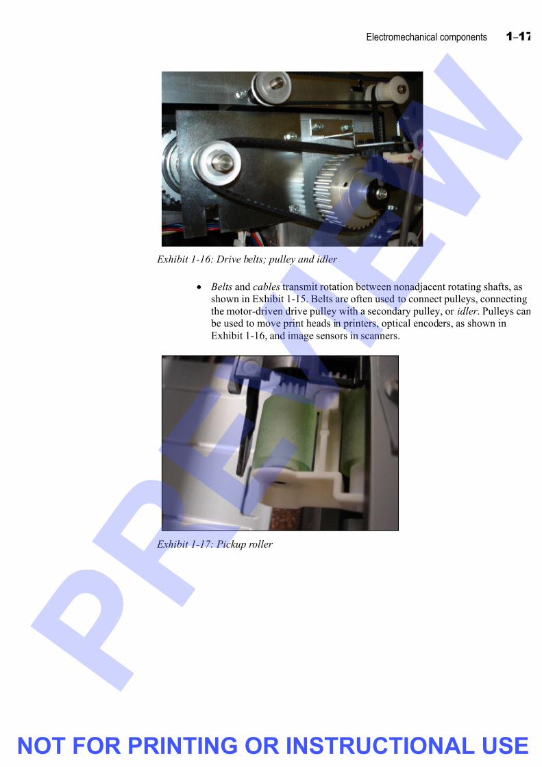
Exhibit 1-16: Drive belts; pulley and idler
• Belts and cables transmit rotation between nonadjacent rotating shafts, as
shown in Exhibit 1-15. Belts are often used to connect pulleys, connecting
the motor-driven drive pulley with a secondary pulley, or idler . Pulleys can
be used to move print heads in printers, optical encoders, as shown in
Exhibit 1-16, and image sensors in scanners.
Exhibit 1-17: Pickup roller
NOT FOR PRINTING OR INSTRUCTIONAL USE

7/26/2019 pdi+ layout
http://slidepdf.com/reader/full/pdi-layout 40/104
1 – 18 CompTIA PDI+ Certification
Exhibit 1-18: Steel roller
• Rollers are smooth, axle-fitted cylinders that serve several functions, including
moving paper through a printer. You find rollers at the beginning of the path,
pulling paper from the tray and into the printer, and at the end of the path,
helping fuse the final image onto the paper. Rollers that aren’t exposed to high
temperatures are usually made of rubber, while those that are exposed to high
temperatures are usually made of steel. Teflon-coated rollers are used in thefuser assembly because of their resistance to heat and their non-stick properties.
Some rollers are driven by motors, such as pickup rollers, and some are idle and
just guide paper out (in larger machines).
Exhibit 1-19: Cams
• A cam is a mechanical component that converts rotation into a push or a
reciprocating (back-and-forth) motion. Cams are employed in a variety of
situations:
– Paper/media feed to pick up, raise, and lower media as it passes through the
print device.
– Paper release levers operate a cam that lowers in order to relieve pressureon the media, so it can be pulled out.
– Cams are sometimes fitted to lift paper inside trays.
– Cams can also lock into various parts, such as toner cartridges, when doors
are closed, because some types of cartridge require motion from motors.
– Cams can be attached to certain shafts in order to close/open photo-
interrupter switches.
NOT FOR PRINTING OR INSTRUCTIONAL USE

7/26/2019 pdi+ layout
http://slidepdf.com/reader/full/pdi-layout 41/104
Electromechanical components 1 –19
Exhibit 1-20: Springs
• Springs are metal coils that are used for a variety of purposes, including
returning moving parts to their home locations and ensuring that paper is loaded
tightly in the tray and ready to be pulled into the printer.
NOT FOR PRINTING OR INSTRUCTIONAL USE
7/26/2019 pdi+ layout
http://slidepdf.com/reader/full/pdi-layout 42/104
1 – 20 CompTIA PDI+ Certification
Do it! B-1: Identifying mechanical components
Here’s how Here’s why
1 What device is used to transfer rotation from one rotating shaft to another?
A gear
2 __________ transmit rotation between nonadjacent rotating shafts.
Belts and cables
3 __________ convert rotation into a push or a reciprocating motion.
Cams
4 __________ are small steel balls used to support rotating shafts and reduce
friction.
Bearings
5 __________ support rotating shafts like bearings, but are made of disposable
material that gradually wears away.
Bushings
6 __________ are smooth, axel-fitted cylinders that move paper through the printer.
Rollers
7 A __________ is a motor-driven shaft that’s connected by a belt or cable to an
idler.
pulley
8 Small metal coils, called __________, are sometimes used to return moving
components to their home location.
springs
NOT FOR PRINTING OR INSTRUCTIONAL USE
7/26/2019 pdi+ layout
http://slidepdf.com/reader/full/pdi-layout 43/104
Electromechanical components 1 –21
Topic C: Electrical components
This topic covers the following CompTIA PDI+ exam objectives.
# Objective
4.3 Identify and explain the function of electrical components
• Power supplies (ie: low and high voltage)
• Fuses
• Thermistors
• Thermal switches/fuses
• Lamps (ie: halogen, xenon, LED)
• Grounding components (ie: screws, shields, points, straps, wires)
• Cables (ie: copper wire harnesses, flat cable, fiber optics)
• Connectors (ie: ZIF sockets, Molex, Ultrex, spade, pin connectors, spring contacts)
• EEPROM and EPROM (ie: NVRAM)
• Memory
• Control PCBs (Printed Circuit Boards) (ie: I/O boards, drivers boards, logic boards, fax
board, network card)
4.4 Demonstrate the proper and safe use of tools
• Multimeter
• Polarity tester
• AC line monitors
8.1 Demonstrate and apply safety procedures
• Use proper ESD (Electrostatic Discharge) practices and proper grounding techniques
• Wrist straps, static mats, unplugging / lockout / tagout
NOT FOR PRINTING OR INSTRUCTIONAL USE

7/26/2019 pdi+ layout
http://slidepdf.com/reader/full/pdi-layout 44/104
1 – 22 CompTIA PDI+ Certification
Power supplies
Explanation A power supply, as shown in Exhibit 1-21, is the internal component that converts wall
voltage (110 V or 220 V) to the various DC voltages used by a computer’s other
components. Inkjet and laser printers both have internal DC power supplies to provide
power to their various internal components, such as the motors and pulleys. But while
inkjet printers have just one DC power supply, laser printers have both a low-voltage
power supply (LVPS ) and a high-voltage power supply (HVPS), the latter ofwhich converts 120 volt, 60 Hz AC current into high-voltage electricity. It’s the HVPS
that powers the primary corona.
Exhibit 1-21: DC high-voltage power supply
Measuring electrical values
When troubleshooting power supply problems, you might need to measure some aspect
of electricity, such as the voltage level output of the power supply. You measure
electrical properties using a device called a multimeter . Multimeters are available in
digital and analog models. Digital multimeters, as shown in Exhibit 1-22, output
discrete numeric values on an LED or LCD screen. Analog multimeters, the older type
shown in Exhibit 1-23, display their output using a needle and dial.
NOT FOR PRINTING OR INSTRUCTIONAL USE

7/26/2019 pdi+ layout
http://slidepdf.com/reader/full/pdi-layout 45/104
Electromechanical components 1 –23
Exhibit 1-22: A digital multimeter
Exhibit 1-23: An analog multimeter
Before taking a measurement with a multimeter, you must set options with a dial,
button, or other means to indicate what you’re about to measure. For example, if you’re
using a meter, as shown in Exhibit 1-22, you press the appropriate buttons to indicate
which electrical property (voltage range) you’re going to read.
NOT FOR PRINTING OR INSTRUCTIONAL USE

7/26/2019 pdi+ layout
http://slidepdf.com/reader/full/pdi-layout 46/104
1 – 24 CompTIA PDI+ Certification
Measuring resistance
To measure resistance:
1 Turn off and disconnect the device you’re measuring from its power source. You
can damage your meter if you leave the device connected to the power source.
2 Additionally, you might need to disconnect the device from its circuit. If it
remains connected and multiple paths through the circuit exist, you’ll get
misleading readings. These readings can be high or low depending on the circuit.
3 Set the multimeter to read resistance. On most meters, you must indicate the
resistance range that you expect to be reading.
4 Touch the two leads of the multimeter together. The meter zeros out and
provides an indication that the meter is functioning properly in the resistance
mode.
5 Touch the black and red probes to either side of the circuit to be measured and
read the resistance from the meter’s display.
Note: If you’re using an analog meter and the needle moves very little or moves all the
way to its maximum, you need to choose another resistance scale. Full scale deflection
could indicate a short.
Measuring voltage
You must exercise care when taking voltage readings while a device is powered up.
To measure voltage:
1 The power supply must be on.
2 Set your multimeter to read either DC or AC voltage. On most meters, you must
also indicate the voltage range that you expect to be reading.
3 Touch the black probe to the ground and the red probe to the spot where you
want to measure the voltage.
If you’re using an analog meter, the needle might attempt to swing backward.
This indicates that you have the red probe on the ground. Reverse your contact
points to take the reading. A digital meter indicates a negative voltage, forexample -55V.
Note: The device must be connected to its power source and turned on while you
measure voltage.
Measuring current
To measure current, you must break the circuit and insert the meter into the break. The
current in the circuit then flows through the meter, which by design, should offer little
disruption and not change the reading appreciably.
A device specifically made for measuring current is called an ammeter . A special formof ammeter, called a clamp-on ammeter, clamps around a single wire to measure the
current flow. Such a meter doesn’t require you to break the circuit. Clamp ammeters are
often used by electricians to measure current flow in 110 V and higher circuits.
Measuring continuity
You can determine if a fuse is good or a wire is whole by measuring continuity. You
might also use this technique to determine which pins on one end of a cable are
connected to which pins on the other end.
NOT FOR PRINTING OR INSTRUCTIONAL USE

7/26/2019 pdi+ layout
http://slidepdf.com/reader/full/pdi-layout 47/104
Electromechanical components 1 –25
To measure continuity, you can either set your multimeter to display resistance (ohms)
and look for circuits with zero resistance, or if your multimeter includes it, you can use
your meter’s continuity mode. In this mode, the multimeter sounds a tone whenever it
detects a closed (unbroken) circuit.
Testing polarity and line status
Improperly wired outlets can easily damage laser printers. Two simple devices can helpdetermine whether an outlet is safe for connecting expensive electronic devices:
• Polarity tester : Many multimeters include an automatic polarity test function.
When you apply the probes, the multimeter’s display indicates normal or
reversed polarity. You can find polarity testers in other multifunction testing
devices, many of which plug into a wall outlet and display results using LEDs or
a small LED screen.
• AC line monitor : This type of monitor plugs into a wall outlet and determines the
integrity of the AC line.
Consult with a licensed electrician to repair damaged or improperly wired outlets.
Do it! C-1: Measuring electrical values
Here’s how Here’s why
1 Using a multimeter, determine the
voltage output of the various
devices provided by your
instructor
Your instructor will provide you with devices,
such as a battery or power adapter, that you can
use to determine output voltages.
Make sure studentsfollow proper electricalsafety during this activity.
Provide students withbatteries, power adapters,good and bad networkcables, and so forth tomeasure.
2 Determine the resistance of the
various components provided by
your instructor
Your instructor will provide you with cables andother components for you to measure.
3 Use a polarity tester/AC linemonitor to test various wall
outlets in the classroom
4 Unplug one of the laser printers in
the classroom, and use proper
ESD and safety procedures to
open the laser printer
Identify the power supplies inside To locate the potentially dangerous electricity
sources are inside a laser printer. Be sure to
follow safety precautions.
Assist students and showthem the proper procedures.
Work with your instructor to
apply lockout and tagout
equipment
To protect against electrical hazards.
5 Remove lockout and tagout
equipment
Close the printer
NOT FOR PRINTING OR INSTRUCTIONAL USE

7/26/2019 pdi+ layout
http://slidepdf.com/reader/full/pdi-layout 48/104
1 – 26 CompTIA PDI+ Certification
Electrical components
The following sections contain descriptions of important electrical components.
Display the componentsor pass them around asyou teach this topic.
Fuses
Exhibit 1-24: Fuses
• A fuse is a disposable, single-use component that protects an electrical circuit
from current overload. The fuse is placed into the circuit, so the electricity flows
through it. If the current in the circuit exceeds the fuse’s rating, a wire in the fuse
melts, opening the circuit and protecting it from overload. Fuses help protect
printer components and prevent against the threat of fire. An example of a fuse
is shown in Exhibit 1-24.
Exhibit 1-25: Thermal switch
• Thermal fuses and thermal switches are similar to fuses, except that they operate
to protect components from excessive heat. Unlike fuses, they don’t respond to
current overload. Thermal fuses are good for one use and then must be replaced;thermal switches, designed for multiple uses, interrupt power to a heating
element if the heat is too high but restore the flow of power when the heat has
returned to an acceptable level.
NOT FOR PRINTING OR INSTRUCTIONAL USE

7/26/2019 pdi+ layout
http://slidepdf.com/reader/full/pdi-layout 49/104
Electromechanical components 1 –27
Exhibit 1-26: Thermistor
• A thermistor (thermal resistor ) is an electrical device that can be used to
measure temperature, such as in the fuser, where correct temperature is critical.
The thermistor’s temperature measurement determines how much power needs
to be passed on to the fuser to ensure its proper operation.
Exhibit 1-27: Lamp from a fuser
• Lamps convert electricity into light and have a variety of applications in printing
and scanning. Light Emitting Diodes (LEDs) can provide users with information
such as printer or scanner settings, device power state, and error and warning
messages. LEDs are also used in the print process itself, to create images on the
photosensitive drum. LEDs provide a cheaper alterative to laser printers but
don’t necessarily produce the same quality output. Halogen lamps are used in
the fusing process to fix the toner to the paper and complete the printing process
Xenon lamps are used in scanners to illuminate the image source during thescanning process.
NOT FOR PRINTING OR INSTRUCTIONAL USE

7/26/2019 pdi+ layout
http://slidepdf.com/reader/full/pdi-layout 50/104
1 – 28 CompTIA PDI+ Certification
Exhibit 1-28: Grounding plate
• Grounding components help protect technicians and sensitive printer
components from ESD and electrical charges by dissipating electricity. Some
grounding components include:
– Ground wires and ground plates, which dissipate electricity by connecting
sensitive components to ground, as shown in Exhibit 1-28. Grounding
screws secure a grounding conductor in place.
– Ground shields, such as copper strand braiding, which eliminate radio
frequency (RF) interference by running it to ground, preventing noise in the
circuit. Ground shielding stops crosstalk and reduces the possibility of ESD
hopping between sensitive components.
Exhibit 1-29: Static mat
– Static mats, as shown in Exhibit 1-29, which allow excess static to run
away from components and safely to ground, can be used on floors or work
surfaces. A grounding point connects static mats to ground by a wire.
NOT FOR PRINTING OR INSTRUCTIONAL USE

7/26/2019 pdi+ layout
http://slidepdf.com/reader/full/pdi-layout 51/104
Electromechanical components 1 –29
Exhibit 1-30: Wrist strap
– Grounding wrist straps, as shown in Exhibit 1-30, and heel straps are worn
by technicians while they’re working on internal components. They help
run excess static to ground. Wrist straps normally have a 1-4 mega ohm
resistor , a component that limits the amount of electricity that can flow
through it. Wrist straps are grounded to a workbench by a clip or similar
attachment.
Flat cable
Wire harness
Exhibit 1-31: Flat cable and wire harnesses
• A variety of cables connect components within a printer or scanner. For visual
convenience, accessibility, and general organization, insulated wires are bundled
together inside devices, such as plastic ties or cords, forming what’s known as a
wire harness, several of which are shown in Exhibit 1-31. Often, wires are
bundled in sets and, sometimes, sets of sets. In printers, wire harnesses typically
secure the wires that connect boards to other boards.
– Flat cable, or ribbon cable, as shown in Exhibit 1-31, so named because
the individual signal wires are side by side. Ribbon cable is normally found
inside a device, connecting internal components or connecting external
ports to the logic board.
– Fiber optic cabling, which carries data on a beam of light, is used to
connect high-end networked printers to the local area network. Fiber optic
provides the fastest network speeds available today. At this time, fiber optic
interfaces aren’t commonly found on printers.
NOT FOR PRINTING OR INSTRUCTIONAL USE

7/26/2019 pdi+ layout
http://slidepdf.com/reader/full/pdi-layout 52/104
1 – 30 CompTIA PDI+ Certification
Lever
Exhibit 1-32: ZIF socket
• You find several types of connectors inside printers, scanners, and multifunction
devices:
– Zero insertion force (ZIF) sockets are designed to make it easy to connect
memory and other chips and integrated circuits on a circuit board without
the risk of damaging them in the process. ZIF sockets have a lever that you
can use to loosen or tighten the connection, without having to push or pull
on the chip you’re trying to insert or remove.
Exhibit 1-33: Molex
– Molex connectors, an example of which is shown in Exhibit 1-33, are 4-pin
DC power connectors.
– An Ultrex connector is a block-shaped circuit-board connector. Ultrex
connectors are used to connect the PCB to sensors or even other PCBs.
– Spade connectors have a forked end, which is clamped down under a
connecting screw to ensure secure contact.
– Pin connectors are exactly what the name implies: the connection is made
by inserting the pins on the male end of the connector into the
corresponding sockets on the female end.
NOT FOR PRINTING OR INSTRUCTIONAL USE

7/26/2019 pdi+ layout
http://slidepdf.com/reader/full/pdi-layout 53/104
Electromechanical components 1 –31
– Spring contacts are often used in doors and trays, where the spring forces
them to return to their home position when the load against them is
removed. Their home position is usually a circuit-open state, which
prevents operation until the necessary doors are shut, pushing the contacts
into the circuit closed state. Spring contacts are also used to ensure that
components, such as toner cartridges, are properly installed.
Exhibit 1-34: Memory modules
• Printers, like computers, have memory chips to hold print jobs as they’re sent
from a computer. Some printers have a standard Random Access Memory (RAM)
chip, such as the one shown in Exhibit 1-34. This type of memory is considered
volatile because its contents are lost when the power supply is turned off.
• Erasable Programmable Read Only Memory (EPROM) is a type of nonvolatile
RAM (NVRAM) that doesn’t lose its contents when the power is removed. You
erase the contents of an EPROM by exposing its glass window to ultraviolet
light.
Exhibit 1-35: EEPROM
• Electronically Erasable Programmable Read Only Memory (EEPROM), as
shown in Exhibit 1-35, is another type of NVRAM that doesn’t lose its contents
when the power is removed.
NOT FOR PRINTING OR INSTRUCTIONAL USE

7/26/2019 pdi+ layout
http://slidepdf.com/reader/full/pdi-layout 54/104
1 – 32 CompTIA PDI+ Certification
Exhibit 1-36: PCB
• A printed circuit board (PCB) is a thin plate into which circuits are printed,
using a thin layer of copper. PCBs also contain memory chips and other
necessary components. PCBs perform all types of input/output (I/O) functions
required to operate a printer or multifunction device, as well as specialized
functions, such as fax and network interface capabilities. A single printer canhave multiple PCBs.
NOT FOR PRINTING OR INSTRUCTIONAL USE

7/26/2019 pdi+ layout
http://slidepdf.com/reader/full/pdi-layout 55/104
Electromechanical components 1 –33
Do it! C-2: Identifying electrical components
Here’s how Here’s why
1 Specialized mats and wrist straps help protect electronic components from
__________.
ESD or static electricity
2 What device is used to monitor temperature in the fuser assembly in a laser
printer?
Thermistor
3 __________ bundle wires to help keep them organized inside electronic devices.
Harnesses
4 __________ convert electricity into light.
Lamps
5 __________ are disposable, single-use components that protect electrical circuits
from current overload.
Fuses
6 __________ temporarily interrupt the flow of electricity to heating elements when
temperatures exceed a predetermined threshold.
Thermal switches
7 Describe the various types of connectors you might encounter inside a printer orscanner.
Answers include: ZIF sockets; Molex, Ultrex, spade, and pin connectors; and springcontacts.
8 Name two types of nonvolatile memory.
EPROM and EEPROM
9 __________ perform all types of I/O functions inside a printer.
PCBs
NOT FOR PRINTING OR INSTRUCTIONAL USE

7/26/2019 pdi+ layout
http://slidepdf.com/reader/full/pdi-layout 56/104
1 – 34 CompTIA PDI+ Certification
Unit summary: Electromechanical components
Topic A In this topic, you learned to identify and describe electromechanical components, such
solenoids, motors, relays, and sensors.
Topic B In this topic, you learned to identify and describe mechanical components, such as
gears, rollers, cams, and pulleys.
Topic C In this topic, you learned to identify and describe electrical components, such as fuses,
thermistors, lamps, memory, and PCBs.
Review questions
1 __________is the force of electricity caused by a difference in electrical potential at
two locations.
Voltage
2 In the United States, electrical systems in office buildings typically operate at what
voltage?
A 85
B 110
C 145
D 210
3 Which of the following is a measure of the flow of electrons past a given point?
A Voltage
B Amps
C Ohms
D Current
4 Current is measured in __________.
Amps or amperes
5 True or false? Current that flows in a single direction at a constant voltage through a
circuit is called direct current.
True
6 True or false? Direct current is the type of electrical current supplied by a typical
office building’s electrical system.
False
NOT FOR PRINTING OR INSTRUCTIONAL USE
7/26/2019 pdi+ layout
http://slidepdf.com/reader/full/pdi-layout 57/104
Electromechanical components 1 –35
7 Which of the following describes the force that opposes the flow of AC through a
conductor?
A Resistance
B Wattage
C Voltage
D Impedance
8 Which of the following describes the force that opposes the flow of DC through a
conductor?
A Resistance
B Wattage
C Voltage
D Impedance
9 True or false? It takes more than 10,000 volts of static electricity to damageelectronic components in most modern devices.
False
10 __________ are typically used to engage rollers for paper pickup from paper trays
and cassettes.
Clutches
11 True or false? Stepper motors allow for a finer range of motion than typical DC
motors.
True
12 Relays that are normally open will _________ when energized by anelectromagnetic field.
close
13 Which of the following powers the primary corona?
A HVPS
B LVPS
C Stepper motor
D Clutch
14 __________ encoders are used to determine location, direction, or both.
Optical
15 A __________ switch is actuated by a physical motion, whereas a magnetic switch
is actuated by a magnetic field.
micro
NOT FOR PRINTING OR INSTRUCTIONAL USE

7/26/2019 pdi+ layout
http://slidepdf.com/reader/full/pdi-layout 58/104
1 – 36 CompTIA PDI+ Certification
16 __________ are used to reduce friction in place of bearings.
Bushings
17 True or false? Rollers can be made of both steel and rubber.
True
18 Which of the following are used to convert rotation into a reciprocating motion?
A Gears
B Bushings
C Cams
D Pulleys
19 Which of the following is used to monitor temperature?
A HVPS
B Multimeter
C Thermistor
D Corona
20 You use a __________ to measure electrical properties.
multimeter
21 Which of the following lamps is often used in scanners as a light source during the
scanning process?
A Xenon
B HVPS
C Halogen
D Diodes
22 __________ helps protect sensitive electronic components from ESD.
Grounding
23 True or false? Ribbon cable is used to connect networked printers to the local
network.
False
24 Which of the following connectors has a forked end that’s secured under a tightenedscrew?
A Molex
B Ultrex
C Spade
D Pin
NOT FOR PRINTING OR INSTRUCTIONAL USE

7/26/2019 pdi+ layout
http://slidepdf.com/reader/full/pdi-layout 59/104
Electromechanical components 1 –37
Independent practice activity
In this activity, you’ll identify electromechanical components. (Note: Be sure the
devices you use are NOT connected to a power supply. Be sure to follow proper
electrical safety and ESD procedures.)
1 Use the printer provided to you to identify the electromechanical components you
learned about in this unit. Make notes detailing the name and location of each
component you were able to identify. If necessary, make a quick sketch of the
component and its location in the printer, and describe its function. You might not
be able to find every component listed in this unit.
NOT FOR PRINTING OR INSTRUCTIONAL USE

7/26/2019 pdi+ layout
http://slidepdf.com/reader/full/pdi-layout 60/104
1 – 38 CompTIA PDI+ Certification
NOT FOR PRINTING OR INSTRUCTIONAL USE
7/26/2019 pdi+ layout
http://slidepdf.com/reader/full/pdi-layout 61/104
2–1
U n i t 2
Printing and scanning
Unit time: 150 minutes
Complete this unit, and you’ll know how to:
A Identify and describe the steps and
components involved in ink dispersion and
electrophotographic printing.
B Identify and describe the steps and
components involved in scanning.
NOT FOR PRINTING OR INSTRUCTIONAL USE

7/26/2019 pdi+ layout
http://slidepdf.com/reader/full/pdi-layout 62/104
2 – 2 CompTIA PDI+ Certification
Topic A: Printing
This topic covers the following CompTIA PDI+ exam objectives.
# Objective
1.1 Define, describe and demonstrate an understanding of the following commonly usedprinting processes:
• Identify and describe basic steps of laser / LED printing
• Photoconductor preparation, charging, writing, developing, transferring, fusing
• Photoconductor preparation
• Removal of residual toner by cleaning blade, brush or roller
• Removal of residual charge by light or electrical charge
• Charging
• Supply uniform charge to the photoconductor surface by charge corona orcharge roller
• Writing
• Laser or LED creates a latent image by discharging the appropriate areas of the photoconductor
• Developing
• Toner is attracted to the latent image
• Transferring
• Toner is transferred from the photoconductor to the media by using electrostaticcharges
• Fusing
• Toner is fixed/fused to the media with heat and pressure
• Identify and describe basic steps of Ink dispersion printing
• Purging, ink delivery, image application to media
• Purging
• Cleaning the heads and nozzles
• Ink delivery
• Ink is moved from reservoir to print head
• Unidirectional and Bi-directional printing
• Image application to media
• Ink is delivered through the nozzles (print head) directly to media via
heat/charge
NOT FOR PRINTING OR INSTRUCTIONAL USE

7/26/2019 pdi+ layout
http://slidepdf.com/reader/full/pdi-layout 63/104
Printing and scanning 2 –3
# Objective
1.2 Identify and describe print process components and their functions
• Laser or LED image formation components
• Photoconductor
• Laser Unit (beam detector, polygon mirror / motor, laser diode, toner shield) or LED unit
• Developer Unit (toner supply, mono component, vs. dual component)
• Charge assembly
• Cleaning Unit (residual toner removal)
• High Voltage Power Supply
• Low Voltage Power Supply
• Transfer / separation
• Device fuser components
• Heat roller / belt, pressure roller, lamps / heaters, thermistor, fuser cleaning components, pawls, thermal protection
• Ink dispersion image formation components
• Print head, IDS (ink delivery system), carriage, carriage belt, ink supply, purge unit,
absorption pads.
• Media transport/feed components
• Pickup roller, feed roller, separate roller/pad, torque limiter, transport rollers, registration
assembly, sensors, media guides, exit rollers, gates/diverters/deflectors, static brushes
• Ventilation components
• Fans, ozone filters, dust filters, ducts
• Accessories
• Finishers, sorters, large capacity paper source, document feeders, stapler, duplexers, punch
units, folders cutters, binders, stackers, inserter.
1.3 Describe the purpose of firmware
1.4 Identify and describe print data flow and job processing
• Demonstrate awareness of the interaction between software application, driver, printercontrol languages, raster image processing, printing and image creation.
• Identify the impact of memory on the printer
1.5 Identify media types and explain their impact on print process, quality and device
performance
• Use appropriate media types based on device specifications
• Identify and recognize paper weights, sizes and standards
• Identify and recognize paper textures, brightness, grain, coatings
• Identify and recognize other media types (ie: transparencies, envelopes, labels, card stock,
raised letterhead, recycled paper)
• Describe adverse affects of improper media storage on device performance
NOT FOR PRINTING OR INSTRUCTIONAL USE

7/26/2019 pdi+ layout
http://slidepdf.com/reader/full/pdi-layout 64/104
2 – 4 CompTIA PDI+ Certification
# Objective
6.1 Identify and describe the basics of color theory
• Differentiate between additive and subtractive color (RGB vs. CMYK)
• Describe color gamut and its relationship to device limitations
• Explain perception of color and what affects perception
• Light, media, contrast, the observer
6.2 Define and explain basic color management
• Identify how color adjustments affects the quality of image output
• Describe the need for color calibration
Windows print process
Before a printer powers up and puts toner or ink to paper, a computer must send data to
the printer, either through a cable between the printer and the computer or across a
network. The print process in Windows XP (and earlier) has been upgraded in WindowsVista (although Windows Vista also supports the Windows XP print process for printers
that don’t meet the new specifications). You’ll learn about both in the following
sections.
Windows XP
The Windows XP print process can be broken down into the following steps:
1 A user prints from within a Win32 application, and a new print job is created. A
Win32 application is an application developed using the Windows application
programming interface (API), which is a set of rules and constructs that
developers use to create Windows applications. Typically, almost any modern
application you use on a Windows 2000 or later computer is a Win32application.
2 The application calls the Graphics Device Interface (GDI). The GDI is a
Windows operating system component that renders graphics for output on a
printer or a monitor. GDI enables the computer to handle most of the print job
processing.
3 The GDI either renders the print job independently, as an enhanced metafile
(EMF), or it calls the GDI-based printer driver to determine how to render the print job for the selected printer. The printer driver also determines if the printer
is online and ready to print.
4 The GDI sends the print job to the spooler .
5 The spooler components work together to further refine the print job by providing layout information and formatting it for the selected printer. The
spooler also inserts print job instructions into the data stream it sends to the
printer.
6 The spooler sends the print job to the printer, which could be either a local or
network printer. The printer stores some of the print job in a RAM buffer , which
is a temporary data store that allows the printer to accept a print job and begin
printing without having to wait for the computer to release the job one page at a
time.
NOT FOR PRINTING OR INSTRUCTIONAL USE

7/26/2019 pdi+ layout
http://slidepdf.com/reader/full/pdi-layout 65/104
Printing and scanning 2 –5
GDI printers don’t require the computer to communicate using a printer control
language (PCL), such as PostScript or Print Command Language ( also known as PCL).
A GDI print device uses the raster image, or dot pattern, that represents the final printed
image, from the computer, rather than compiling the raster image itself.
Some devices, such as some laser printers, compile the raster image themselves in the
onboard Raster Image Processor (RIP). Because much of the processing for these print
jobs is done on the printers, the printers must have a sufficient amount of RAM to process all the pages in the print job. More complicated images or those with high
resolutions might require a larger amount of RAM than a printer has installed, which
event can cause the printer to generate memory errors. You can work around these
memory errors by reconfiguring the print job (e.g., reducing the resolution or dividing
the job into smaller jobs) or installing additional memory in the printer.
Windows Vista
Windows Vista supports a new print specification called XML Paper Specification
(XPS). While Windows Vista still provides backward support for GDI print devices and
Win32 applications, newer XPS print devices and Windows Presentation Foundation
(WPF) applications use a different print process from those used in Windows XP and
earlier Windows operating systems. In this new process, the WPF applications call onWPF support functions to spool the document to the spooler in XPS format. If the
printer supports XPS and has an XPSDrv printer driver, the spooler sends the spooled
XPS file to the XPSDrv printer driver for output to the printer. However, if the printer
has a GDI-based driver, the spooler sends the XPS print job to the GDI Conversion
Module to be converted to an EMF file.
Do it! A-1: Examining the Windows printing process
Questions and answers
1 What’s different about the Windows XP and Windows Vista print processes?
Windows Vista supports a print process that uses the new XPS specification, although it stillsupports the same process that’s found on Windows XP computers.
2 Describe the function of the GDI.
The GDI is a Windows component that renders graphics for output to a monitor or printer.The GDI is responsible for taking the print job from the applications, processing it using the
print driver, if necessary, and handing the print job off to the spooler.
3 Describe the function of the spooler.
The spooler takes the print job from the GDI, further refines it, as necessary, by adding
layout information and print instructions, and sends the print job to the printer.
4 Where’s the raster image created?
Either on the computer, where it’s then sent to the printer, or on the printer itself using theonboard RIP.
5 What happens on a Windows Vista computer when you print to a non-XPS
compliant printer?
The XPS print job is sent to the GDI Conversion Module for processing.
NOT FOR PRINTING OR INSTRUCTIONAL USE

7/26/2019 pdi+ layout
http://slidepdf.com/reader/full/pdi-layout 66/104
2 – 6 CompTIA PDI+ Certification
Color theory
Explanation Color printing has become widespread with the introduction of inexpensive color inkjet printers. Even color laser printers are becoming more common, as their price drops in
relation to monochrome (black-and-white) laser printers. As a technician, you’re
expected to understand the basics of color theory and how color printers create colored
text and graphics on the printed page.
Each ray of light is composed of waves that vibrate at various speeds. How the human
eye responds to each wavelength determines how we perceive color. When light passes
through a prism, the light is bent, or refracted, and the various wavelengths can be seen
separately when reflected off a white surface. The colors we see in the refracted light are
known as the spectrum, which is composed of the following colors:
• Red
• Orange
• Yellow
• Green
• Blue
• Indigo (or blue-violet)
• Violet
All these wavelengths together create white light. Mixed separately in various
combinations, they create various hues, or colors in the spectrum.
In the science of color mixing, there are two models: additive color , the method ofcreating color by mixing colored lights, and subtractive color , the method of creating
color by using light reflected off pigment in paint or ink.
Additive color
Additive color process is the method of creating the color spectrum by mixing colored
light. The resulting color combinations come not from a property of the light itself butinstead from how the eye perceives color. This color model is also known as RGB for
the three main colors used: red, green, and blue, also known as additive primaries.
When these three colored lights are projected together, they create white light. When
combined in pairs they create the additive secondaries of cyan (blue+green), magenta
(red+blue), and yellow (red+green).
Because the additive color model uses light rays to create colors, there must be a light
source. Additive color is used to create a wide range of colors in color monitors and
color projectors. Newer monitors and video adapters can produce millions of colors
using this color model.
Subtractive color
The subtractive color process is the method of creating the color spectrum using pigment. White paper reflects all light wavelengths back to the viewer, but when
pigment is applied, some of the light isn’t reflected. Light that isn’t reflected is absorbed
by the pigment and is said to be subtracted from the light that’s reflected. The
wavelength subtracted from the reflected light—the wavelength absorbed by the
pigment—is perceived as color by the human eye. It’s this method that printingtechnologies use for creating color.
NOT FOR PRINTING OR INSTRUCTIONAL USE

7/26/2019 pdi+ layout
http://slidepdf.com/reader/full/pdi-layout 67/104
Printing and scanning 2 –7
In printers, the pigment is contained in ink (ink dispersion printers) or toner
(electrophotographic printers). The subtractive color model is also known as CMYK for
the four main colors used: cyan, magenta, yellow, and black. The letters CMYK are
used rather than CMYB so that the B isn’t misunderstood to mean blue. The K is from
the last letter of "black," although experts in color printing technologies will tell you
that K is for “key,” which refers to a component in traditional color printing that uses
black ink.
A combination of the CMY is used to create the color spectrum, and all three colors
together create black. A separate black source (ink or toner) is used, because black is the
most heavily used color, especially for text, and a separate black pigment reduces waste.
Color printing
Color printing presents some additional challenges not found in monochromatic
printing. While some devices can print in color, not all devices provide the same quality
color output. Color gamut is the term used to describe the entire range of colors a
printing device can produce. Typically printers with better monochromatic print quality
produce better color pages when printing with color ink or toner, resulting mostly from
the printer’s ability to create high-resolution text and graphics, measured in dots per
inch (DPI). However, this isn’t always true. And while a photograph or other graphicimage might be rendered brilliantly on a monitor, the device’s limitations might prevent
it from being rendered on paper with comparable clarity. A device with a larger color
gamut produces a greater number of colors and thus produces a printed page that more
closely resembles the onscreen image.
In addition, the perception of color on the printed page is affected by a number of
factors, including the viewer’s vision and ability to perceive color, ambient light, the
type of paper or other media on which the text and graphics are printed, and the contrast between the printed text and graphics and the background. Bright light can make colors
appear deeper and more saturated, while low light can make colors appear muted.
Different colored paper, even paper that’s white as opposed to “bright white,” can affect
the clarity and brilliance of color, mostly a function of the contrast between the
background and the pigment. And of course, a viewer with poor vision or impairedability to perceive color finds printed colors less vivid than a viewer without such
impairments, regardless of a printer’s ability to reproduce color, the type of media, or
the ambient light. Even two people with excellent eyesight perceive color differently.
Color printers also require careful calibration to ensure that all the colors are properly
aligned on the page. Registration errors occur when colors are misaligned, producing
blurry and out-of-focus images. Color printers usually provide a test function that lets
you print a test page and adjust or realign print heads or other printer components to
ensure that colors appear properly aligned on the printed page.
NOT FOR PRINTING OR INSTRUCTIONAL USE

7/26/2019 pdi+ layout
http://slidepdf.com/reader/full/pdi-layout 68/104
2 – 8 CompTIA PDI+ Certification
Do it! A-2: Discussing color theory
Here’s how
1 Describe the additive color process.
Additive color process is the method of creating the color spectrum by mixing colored light.
2 What are the additive primaries?
Red, green, and blue.
3 Describe the subtractive color process.
The subtractive color process is the method of creating the color spectrum using pigment ona white background. Light absorbed by the pigment isn’t reflected, so the resulting color issaid to have been subtracted from the reflected light.
4 What colors are used in the subtractive color process?
Cyan, magenta, yellow, and black.
5 What’s a device’s color gamut?
The entire range of colors a device can produce.
6 Name several factors that affect color perception. Why is calibration important?
Answers include ambient light, media, contrast between pigment and background, and theviewer’s ability to perceive colors. Calibration ensures colors are properly aligned on the
printed page so images are crisp and in focus.
NOT FOR PRINTING OR INSTRUCTIONAL USE

7/26/2019 pdi+ layout
http://slidepdf.com/reader/full/pdi-layout 69/104
Printing and scanning 2 –9
Inkjet print process
Explanation Inkjet printers, also known as ink dispersion printing technology, produce images by
forcing ink through tiny nozzles and onto the paper. Each nozzle is approximately 50 to
60 microns in diameter. Most inkjet printers are designed to be everyday printers for a
variety of documents from text to graphics, while some inkjet printers are designed just
for printing photos. These are often small printers, as shown in Exhibit 2-1, that can
print 4 x 6-inch or smaller photos on specialty paper.
Exhibit 2-1: Inkjet printer
The printer is controlled by a PCB, also known as a logic board . The logic board
contains the memory chips that hold the page information while the print job is
processed, and the firmware, which is the onboard software that controls the printer’s
functions. Firmware controls not just the print process but all aspects of the printer’s
operation, including communication with an attached computer and any built-innetworking or communication capabilities, especially in multifunction units.
The inkjet print process is less complicated than the electrophotographic (EP) print
process and contains fewer components. There are three main stages to the inkjet print
process:
1 Purging
2 Ink delivery
3 Image application to media
NOT FOR PRINTING OR INSTRUCTIONAL USE

7/26/2019 pdi+ layout
http://slidepdf.com/reader/full/pdi-layout 70/104
2 – 10 CompTIA PDI+ Certification
Exhibit 2-2: Inkjet print head
Purging
The first step in the inkjet print process is purging. In this step, the print enters a short
cycle, during which the print heads are cleaned. Each print head, an example of which is
shown in Exhibit 2-2, contains hundreds of minute openings, or nozzles, through which
ink droplets are sprayed during the inkjet print process. The print head on an inkjet
printer is usually part of the ink cartridge. Because this part typically wears out the
soonest, having it replaced each time you replace the ink means you always have a good
print head.
Exhibit 2-3: Ink cartridges
Each nozzle is connected to a channel that runs directly to the ink cartridge. Ink
cartridges are the reservoirs that hold ink for inkjet printers. The number of cartridges
varies from printer to printer, but most inkjet printers have a black cartridge and a colorcartridge, with compartments for cyan, magenta, and yellow. Some printers have
separately replaceable cartridges for each color. Some printers have more colors than
these basic ones. Some inexpensive printers don’t have a separate black cartridge.
Instead, when black is required, they mix all three colors together to produce a dark
color. Exhibit 2-3 shows examples of inkjet cartridges: a single color cartridge that
contains the cyan, yellow, and magenta inks, and a separate black-ink cartridge, which
holds black ink or black and color inks for color inkjet printers.
NOT FOR PRINTING OR INSTRUCTIONAL USE

7/26/2019 pdi+ layout
http://slidepdf.com/reader/full/pdi-layout 71/104
Printing and scanning 2 –11
The ink is always in the channels and at the ready in each nozzle. Two things keep the
ink from dripping out:
• Viscosity, a property of liquids that describes their ability to flow. The higher the
viscosity of a liquid, the less likely the liquid will flow; conversely, the lower the
viscosity, the more likely the liquid will flow.
• Surface tension, another property of liquids that’s used to describe the elasticity
of an unbroken liquid surface.Because the ink in each nozzle is exposed to air, it evaporates and its viscosity
increases, causing it to harden and eventually clog the nozzles. During the purging
cycle, a small amount of ink is forced through the channels and out of the nozzles and
onto a small sponge or absorbent pad in a component sometimes known as a purge unit .
This ensures that the nozzles are clean and ready to use in the next step of the inkjet
print process. In some inkjet printers, the print head is also cleaned using a sponge or
pad and a wiping or blotting movement created by the motion of the carriage assembly.
The ink cartridges, print head, and associated parts are known collectively as the ink
delivery system (IDS).
Ink deliveryAfter the purge cycle, the motor that controls the pickup rollers engages and draws a
sheet of paper into the paper path. Some inkjet printers have a paper tray behind the
printer and pull the paper through the printer on a straight-through paper path using a set
of feed rollers. This setup leads to fewer paper jams and is good for heavy paper stock.
Exhibit 2-4 shows a straight-through paper path in an inkjet printer.
Exhibit 2-4: Straight-through paper path
NOT FOR PRINTING OR INSTRUCTIONAL USE

7/26/2019 pdi+ layout
http://slidepdf.com/reader/full/pdi-layout 72/104
2 – 12 CompTIA PDI+ Certification
Other printers store the paper in a tray below and to the front of the printer then pull the
paper up through feed rollers and under the print head. Printers using this technology
pull the paper up through an S-curve or a U-curve. Exhibit 2-5 shows a curved paper
path in an inkjet printer. In both types of paper tray, simple switches detect the presence
of paper and can alert you if the paper runs out using a small LED warning.
Exhibit 2-5: Curved paper path
Because the nozzles have been purged, fresh ink is now moved into position at each
nozzle on the print head in a process known as priming . When printing begins in the
next step of the process, some inkjet printers print on both passes across the page: left to
right and right to left. Other printers print in only one direction, either right to left or left
to right. The first type of printer is said to be bidirectional ; the second type of printer is
said to be unidirectional .
Image application to media
There are two methods of forcing ink through the nozzles: thermal bubble and
piezoelectric bubble.
• Thermal bubble technology heats the ink until it vaporizes, creating a bubble.
The bubble protrudes out through the nozzle and sprays onto the paper. When
the bubble bursts, it creates a vacuum, which draws more ink from the cartridge
into the print head, readying it to create the next dot.
• Piezoelectric technology creates a bubble using a piezo crystal behind each
nozzle. An electrical current sent to the crystal causes it to vibrate. When it
vibrates inward, it releases ink onto the paper; when it vibrates outward, it pulls
ink from the cartridge.
The stepping motor drives the belt that moves the carriage containing the print head
across the page, stopping for a fraction of a second for the ink droplets to be sprayed
onto the paper. The motion of the stepping motor is so fluid that it isn’t visible to the
naked eye. Depending on the type of printer, one of three things happens:
• the print head makes another pass at the same line
• the paper advances and the print head starts back in the other direction, printing
a new line as it goes, as with bidirectional printers
• the print head returns, the paper advances, and the print head starts on a new
line, as with unidirectional printers
NOT FOR PRINTING OR INSTRUCTIONAL USE

7/26/2019 pdi+ layout
http://slidepdf.com/reader/full/pdi-layout 73/104
Printing and scanning 2 –13
When printing is complete, the stepping motor that has been advancing the paper ejects
the printed page, and the print head returns to its home position. Most inkjet printers use
a fast drying ink, so the page is safe to touch after it’s been ejected. Some photo printers
or images on paper that contain a lot of ink might take a few seconds or a few minutes
to dry before they’re safe to touch.
Do it! A-3: Examining the inkjet print process
Here’s how Here’s why
1 Observe the inkjet printers at your
instructor’s work station
Be sure to follow standard ESD and electrical
safety procedures.
2 Work with your instructor and
other students to identify as many
of the printer’s components as you
can
Refer to the book, if necessary.
3 Watch as your instructor prints
several test pages and explains theinkjet print process
Be sure to have workingand non-working inkjet printers ready beforestarting this activity. Theworking inkjet printershould be connected toyour computer and readyto print.
Open the cover and pointto various parts. Askstudents to identify each part you point to.
As you print several pages, walk studentsthrough the steps in theinkjet print process. Youmight need to print several pages. Discuss both thesoftware and hardwareaspect of the process.
4 Work with your instructor toidentify the various steps as each
page is printing
NOT FOR PRINTING OR INSTRUCTIONAL USE

7/26/2019 pdi+ layout
http://slidepdf.com/reader/full/pdi-layout 74/104
2 – 14 CompTIA PDI+ Certification
Exhibit 2-6: Laser printer
Electrophotographic print process
Explanation EP printers (laser and LED) provide the standard level of quality to which other printers
are measured. EP printers can create high-quality documents in a high-volume printing
environment, but as you might expect, the EP print process is more complicated than the
inkjet print process. Most EP printers produce black-and-white output, but color EP
printers are widely available. Exhibit 2-6 shows an example of a laser printer.
Like those of an inkjet printer, an EP printer’s functions are controlled by the logic
board. To store their firmware, laser printer logic boards typically contain much more
RAM and EPROM or EEPROM chips than inkjet printer logic boards.
The EP print process consists of the following steps:
1 Photoconductor preparation
2 Charging
3 Writing
4 Developing
5 Transferring
6 Fusing
NOT FOR PRINTING OR INSTRUCTIONAL USE

7/26/2019 pdi+ layout
http://slidepdf.com/reader/full/pdi-layout 75/104
Printing and scanning 2 –15
Exhibit 2-7: A drum exposed
Developer
Photoconductive
drum
Cleaning blade
Exhibit 2-8: Drum in place
Photoconductor preparation
Display anycomponents you havein the classroom asyou discuss them inthe following sections.
The photoconductor , or drum, as shown in Exhibit 2-7 and Exhibit 2-8, is an aluminum
cylinder that’s coated with a photoconductive material. The material is said to be
photoconductive, because it conducts electricity when it’s exposed to light, in this case alaser beam or an array of LEDs. The drum is grounded to the power supply, but the
photosensitive coating isn’t, so any charge the aluminum drum receives bleeds away
into the grounding. However, the coating remains conductive.
NOT FOR PRINTING OR INSTRUCTIONAL USE

7/26/2019 pdi+ layout
http://slidepdf.com/reader/full/pdi-layout 76/104
2 – 16 CompTIA PDI+ Certification
Cleaning brush
Cleaning blade
Exhibit 2-9: Cleaning unit
Because the drum is so integral to the process, it must be clean and free of any toner
residue or electric charge. A rubber cleaning blade or brush, as shown in Exhibit 2-8
and Exhibit 2-9, removes any toner from the surface of the drum. The toner is scraped
back into the original toner supply or into a collection chamber that’s part of the
developer unit, so it’s disposed of when you remove and replace the unit. If the toner
isn’t removed from the drum, residual toner appears on subsequent pages as small spots
and flecks.
The drum is also exposed to erasure or discharge lamps to ensure that any charges
written to the drum’s photosensitive surface by the laser or LED array are removed orreversed. This process prevents phantom images from making their way onto
subsequent pages.
Exhibit 2-10: Primary charge corona assembly
NOT FOR PRINTING OR INSTRUCTIONAL USE

7/26/2019 pdi+ layout
http://slidepdf.com/reader/full/pdi-layout 77/104
Printing and scanning 2 –17
Charging
After the drum is prepared, it’s charged by the primary corona, as shown in Exhibit 2-
10, or the charge roller , as shown in Exhibit 2-11. A printer has either one or the other,
and it’s connected to the high-voltage power supply (HVPS). (A low-voltage power
supply powers other printer components.) This step is also called conditioning .
Exhibit 2-11: Charge roller
Both the corona and roller apply a negative charge of around -600V to the surface of the
drum, the corona by creating an electrical field between it and the drum, and the charge
roller by direct contact. The electrical field generated by the primary corona changes the
air between it and the drum into ozone, so printers with a corona always have an ozonefilter and exhaust component.
Writing
After the drum has been charged, it’s ready for the next step: the laser or LED array
writes the image to be printed onto the surface of the drum by removing the negative
charge—in effect, cutting out the patterns of the letters and graphics that make up the
final printed page. By exposing areas of the drum to precise beams of light, the printer
creates an image on the surface of the drum by discharging the -600V charge to about -
100V. It’s this discharged image, which is basically a series of dots, that attracts the
negatively charged toner in the next step where the image is positively charged in
relation to the stronger negative charge on the rest of the drum.
Exhibit 2-12: Laser unit
In a laser printer, the laser unit, as shown in Exhibit 2-12, is responsible for writing the
image onto the drum. The laser is emitted from a laser diode, which is a tiny eye
(aperture) that measures at most only a few millimeters in diameter.
NOT FOR PRINTING OR INSTRUCTIONAL USE

7/26/2019 pdi+ layout
http://slidepdf.com/reader/full/pdi-layout 78/104
2 – 18 CompTIA PDI+ Certification
Designs vary, but a typical diode is set in a metal, cylindrical mounting. Some are set
directly in the wall of the laser unit.
The laser is focused through a lens and reflected off a motorized polygon mirror to
expose, and as a result discharge, a single row of dots. The drum is stopped while each
row is discharged and advanced when each row is completed. The beam detector is
responsible for tracking the location of the laser beam. The stopping and starting is
coordinated with the motion of the laser beam and is virtually imperceptible. A toner shield protects the integrity of laser beam by preventing toner from entering the laser’s
line of travel or touching the lens or diode.
In an LED printer, a strip of LEDs replaces the laser unit. The LED array doesn’t
require a mirror assembly; instead each LED fires on cue to create the image on the
drum. Typically LED printers are less expensive than laser printers but don’t produce
output of comparable quality. However, as LED technology improves, the quality will
eventually approach that of laser printers.
Exhibit 2-13: Developer unit
Developing
After the invisible image is etched into the electrical charge on the surface of the drum,
it must be developed and made visible. The developer unit , as shown in Exhibit 2-13,
contains the toner supply, which is the “ink” of an EP printer. Toner is a fine powder
made of pigment, either black alone or CMYK, bound to minute plastic beads, and often
superfine metallic particles. There are two types of toner:
NOT FOR PRINTING OR INSTRUCTIONAL USE

7/26/2019 pdi+ layout
http://slidepdf.com/reader/full/pdi-layout 79/104
Printing and scanning 2 –19
Exhibit 2-14: Dual-component toner
• Dual-component toner uses a separate metallic medium to transfer the pigment
to paper. The metallic particles are drawn out of the toner supply, bonding to the
pigment as they move. Exhibit 2-14 shows a package of dual-component
developer that contains an iron oxide mixture and carbon black toner.
• Mono-component toner has the pigment and metallic medium already bound in
the same particle.The toner is kept in a trough in the developer unit, and is exposed to the drum using a
magnetic transfer roller that lifts the toner out of the trough in a thin layer with the help
of a doctor blade (or skimming blade or metering blade), which scrapes the toner into a
single layer on the roller. The negatively charged toner is repelled by most of the drum,
except for the areas that were discharged by the light—the areas that contain the text
and graphics on the printed page. The toner is attracted to these areas and fills them in,
creating the page’s image on the surface of the drum. (You could actually see the image
on the drum if you were to stop it and remove it from the printer during the print
process.)
NOT FOR PRINTING OR INSTRUCTIONAL USE
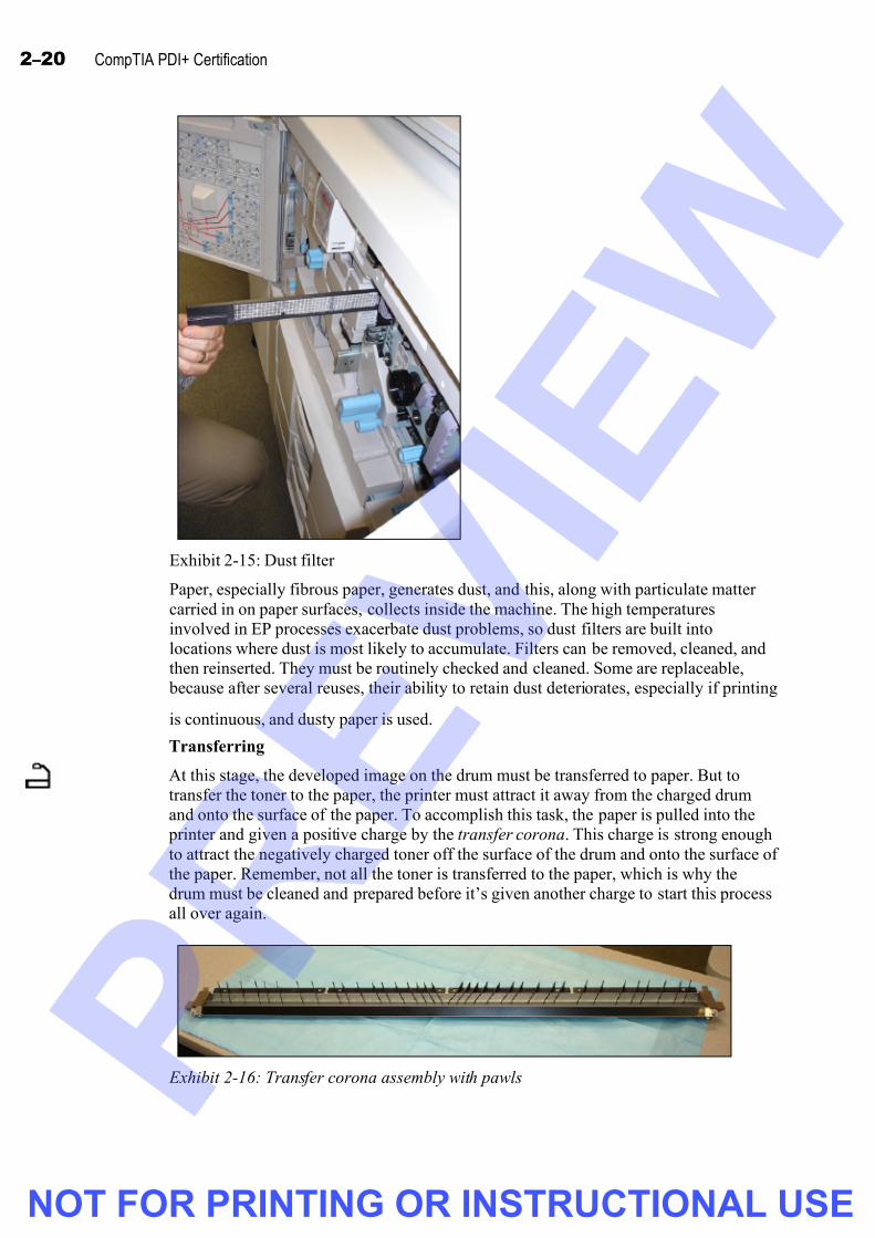
7/26/2019 pdi+ layout
http://slidepdf.com/reader/full/pdi-layout 80/104
2 – 20 CompTIA PDI+ Certification
Exhibit 2-15: Dust filter
Paper, especially fibrous paper, generates dust, and this, along with particulate matter
carried in on paper surfaces, collects inside the machine. The high temperatures
involved in EP processes exacerbate dust problems, so dust filters are built into
locations where dust is most likely to accumulate. Filters can be removed, cleaned, and
then reinserted. They must be routinely checked and cleaned. Some are replaceable,
because after several reuses, their ability to retain dust deteriorates, especially if printing
is continuous, and dusty paper is used.
Transferring
At this stage, the developed image on the drum must be transferred to paper. But to
transfer the toner to the paper, the printer must attract it away from the charged drum
and onto the surface of the paper. To accomplish this task, the paper is pulled into the
printer and given a positive charge by the transfer corona. This charge is strong enough
to attract the negatively charged toner off the surface of the drum and onto the surface of
the paper. Remember, not all the toner is transferred to the paper, which is why the
drum must be cleaned and prepared before it’s given another charge to start this process
all over again.
Exhibit 2-16: Transfer corona assembly with pawls
NOT FOR PRINTING OR INSTRUCTIONAL USE

7/26/2019 pdi+ layout
http://slidepdf.com/reader/full/pdi-layout 81/104
Printing and scanning 2 –21
To help prevent the positively charged paper from sticking to the negatively charged
drum and wrapping around it, the charge on the paper is removed by a static charge
eliminator right after the toner is transferred to the paper. Pawls, claw-like metal
components, in the transfer assembly, such as those shown in Exhibit 2-16, help guide
the paper away from the drum. The paper is then ready for the next step in the process.
Exhibit 2-17: Fuser assembly
Fusing
At this point, the toner is sitting loosely on the surface of the paper, and it’s ready to be
permanently bonded (fused) to the paper. The paper is fed through the fuser assembly
and sandwiched between two rollers: a heated, non-stick roller on top, and a pressureroller on the bottom, which is indicated in Exhibit 2-17 (the heated roller being above
it). Often the nonstick roller is coated with Teflon. As the paper is squeezed between the
two rollers, the toner is melted and forced into the paper, fixing the image permanently.
Pawls guide the paper away from the heated roller and toward the delivery or exit
rollers. A cleaning unit scrubs the surface of the heated roller to ensure the heated roller
is free of any residual toner.
NOT FOR PRINTING OR INSTRUCTIONAL USE

7/26/2019 pdi+ layout
http://slidepdf.com/reader/full/pdi-layout 82/104
2 – 22 CompTIA PDI+ Certification
The heated roller is heated by a lamp, such as a quartz or halogen lamp, or by a heating
coil, to raise its temperature to around 350 degrees Fahrenheit, or 180 degrees Celsius.
Examples of a heating lamp are shown in Exhibit 2-18 and Exhibit 2-19. A thermistor is
used to monitor and maintain the proper temperature by regulating electrical current to
the heating lamps. A thermal switch protects against any spikes in temperature by
cutting the electrical current if the temperature is too high. Fans, such as the one in
Exhibit 2-20, and air ducts help keep air circulating through the printer to help maintain
proper temperature in not just the fuser assembly but also throughout the machine.
Exhibit 2-18: Fusing lamps inside the roller
Exhibit 2-19: Fusing lamp exposed
The heated roller is heated by a lamp, such as a quartz or halogen lamp, or by a heating
coil, to raise its temperature to around 350 degrees Fahrenheit, or 180 degrees Celsius.
A thermistor is used to monitor and maintain the proper temperature by regulating
electrical current to the heating lamps. A thermal switch protects against any spikes in
temperature by cutting the electrical current if the temperature is too high. Fans and air
ducts keep air circulating through the printer to help maintain proper temperature not
just in the fuser assembly but also throughout the machine.
NOT FOR PRINTING OR INSTRUCTIONAL USE

7/26/2019 pdi+ layout
http://slidepdf.com/reader/full/pdi-layout 83/104
Printing and scanning 2 –23
Fan
Exhibit 2-20: Fan
After the paper exits the fuser assembly, it’s pushed out of the printer and into a waiting
tray (or into a finisher for further processing). This process repeats until the entire
document submitted for printing is completed.
Exhibit 2-21: Transfer belt
NOT FOR PRINTING OR INSTRUCTIONAL USE

7/26/2019 pdi+ layout
http://slidepdf.com/reader/full/pdi-layout 84/104
2 – 24 CompTIA PDI+ Certification
Color laser printers
Color laser printers use one of the following processes to produce the colored text and
graphics on the page:
• The printer has four separate developer units, one for each color of toner
(usually CMYK). The drum is discharged once for each color, and successive
layers of colored toner are applied to the drum and then the paper, one color at a
time, to produce the final printed page.• The printer contains a belt or plate that’s the size of a sheet of paper. To build
the image, four different colors of toner are applied, one after the other, to the
belt, a sample of which is shown in Exhibit 2-21, or plate. The combined toner is
then applied to the page as a single image. The toner is then fused to the page as
in the normal monochrome process.
• The printer has separate print process components for each color: a drum,
developer, and fuser. The final printed page is put through all four processes
before finally exiting the printer.
Color printers require more memory than monochrome printers, because each the pagemust be rasterized in each color and stored in memory.
Paper path
The path the paper takes through a laser printer must be precisely controlled in order to
produce the final printed copy. A slight deviation from the correct path can result in a
paper jam, damage to internal printer components, and misprinted or blank pages.
Photo-interrupt and photo-reflective sensors help ensure that the paper is properly
positioned throughout its path through the printer. Sensors also trigger errors if paper
isn’t where it should be or if a jam occurs.
Exhibit 2-22: Pickup roller and separation pad
NOT FOR PRINTING OR INSTRUCTIONAL USE

7/26/2019 pdi+ layout
http://slidepdf.com/reader/full/pdi-layout 85/104
Printing and scanning 2 –25
The following components are responsible for keeping paper on the correct path.
• Pickup rollers (often wedge-shaped and powered by a motor and clutch or
solenoid), in contact with the top of the paper stack, push a single sheet forward
into the closely fitting feed roller (the upper roller) and separation roller or
separation pad (the lower roller). The separation roller knocks away any excess
sheets that have traveled beneath the sheet that was pushed by the pickup roller.
The feed roller pushes or pulls the sheet into the printing area of the device. The
edge of the paper that enters the printer first is called the lead edge or leading
edge.
• A torque limiter in the separation roller helps keep sheets straight by providing
back-feed pressure to sheets as they’re feeding through the paper path. Torque
limiters might also be fitted to feed rollers to limit excess rotation from the
drive. Torque limiters attached to roller shafts might resemble two cylinders or
thick washers. These cylinders are magnetic and, between them, is a cushion of
iron filings. It’s this cushion that neutralizes the torque. Depending on the printer
model, torque limiters can also be found integrated into clutch assemblies.
• The Registration assembly is a series of rollers that keep the paper flat as it’s
drawn into the printer and ensure that it’s properly positioned.
• Transport rollers provide a fluid, rolling surface to facilitate paper movement
through the paper path.
• Media guides ensure that the paper is straight and properly oriented in the paper
path.
Exhibit 2-23: Gates
•
Gates provide a transition from one assembly to another.• Diverters and deflectors help steer paper in one direction or another.
• Delivery or exit rollers move (deliver) the paper to the printer’s exit tray.
• Static brushes remove any residual static electricity from printed sheets.
NOT FOR PRINTING OR INSTRUCTIONAL USE

7/26/2019 pdi+ layout
http://slidepdf.com/reader/full/pdi-layout 86/104
2 – 26 CompTIA PDI+ Certification
Printer accessories
After the print process, the printed page is usually delivered to a tray where you can
pick it up. Many larger printers have a wide range of add-on accessories that you can
use to assemble printed pages in almost any format imaginable. Not all printers support
all the available add-ons.
Exhibit 2-24: Duplexer
• Duplexers allow a printer to print on both sides of a sheet of paper, creatingdouble-sided pages. After the print process is complete on the first side, the
paper is put through the process again for the second side.
• Finishers are add-on units that take the printed pages and complete a job using
any or all of the following features:
• Staplers.
• Punch units, to punch holes so that you can put the finished pages in a
binder.
• Folders.
• Cutters, to cut paper into sizes other than what was fed into the printer; for
example, you can cut pages in half or into quarters if printing tickets orflyers.
• Binders, such as comb or spiral wire binders.
• Inserters, to insert blank or preprinted pages, such as covers, in collated
print jobs.
NOT FOR PRINTING OR INSTRUCTIONAL USE

7/26/2019 pdi+ layout
http://slidepdf.com/reader/full/pdi-layout 87/104
Printing and scanning 2 –27
Exhibit 2-25: Automatic Document Feeder (ADF)
• Sorters and stackers collate finished pages into separate piles that
correspond to the document that was printed or copied (on multifunction
printers). You can feed multipage documents into copiers andmultifunction printers using an automatic document feeder (ADF) such as
the one shown in Exhibit 2-25.
Do it! A-4: Examining the EP print process
Here’s how Here’s why
1 Observe the printers at yourinstructor’s workstation
Be sure to follow standard ESD and electrical
safety procedures.
2 Work with your instructor and
other students to identify as many
of the printer components as you
can
Refer to the book, if necessary.
3 Watch as your instructor prints
several test pages and explains the
EP print process
Be sure to have workingand nonworking EP printers ready beforestarting this activity. Theworking EP printer shouldbe connected to yourcomputer and ready to print.
Open the cover and pointto various parts. Askstudents to identify each part as you point to it.
As you print several pages, walk studentsthrough the steps in theEP print process,discussing both thehardware and softwareaspects.
4 Work with your instructor to
identify the different steps as each
page is printing
NOT FOR PRINTING OR INSTRUCTIONAL USE

7/26/2019 pdi+ layout
http://slidepdf.com/reader/full/pdi-layout 88/104
2 – 28 CompTIA PDI+ Certification
Print media
Paper is the most widely used print medium, although most inkjet and laser printers with
the right software can print on mailing labels, envelopes, CDs, DVDs, and
transparencies. Paper is loaded into paper trays on the sides, the front, the back, or under
the printer. The trays can be exposed or hidden in drawers or cabinets. Paper can also be
loaded into cassettes, which are closed containers loaded with paper and inserted into a
printer. Large capacity paper sources can hold thousands of sheets of paper. This isespecially important for large print jobs, so that users don’t have to replenish the paper
supply constantly.
Most printers can accommodate a variety of paper sizes, weights, and types. However,
the best advice for choosing the proper paper is to check the printer’s documentation
and use the paper recommended by the manufacturer.
Paper grain
A paper’s grain is the direction in which most of the paper’s fibers lie. Grain long is
paper with the grain parallel to the long side, while grain short is paper with the grain
parallel to the short side. The paper should be inserted such that the grain of the paper is
parallel to the lead edge. Check the paper packaging to see how the paper manufacturerrecommends that you insert the paper.
Paper weights
Paper is available in a variety of weights. The weight of a given paper is stated in
pounds (lbs) of an uncut basis ream (500 sheets) of that paper. From the basis ream, the
paper is cut to size and finished before being packaged. So while a basis ream of a 20lbs
paper would weigh twenty pounds, the ream of 20lb paper you buy at the store isn’t
20lbs. (It’s actually closer to 5.)
General-purpose paper is usually 20lb or 24lb paper. Other general use paper can range
up to 32lbs. You can determine the paper weight by examining its packaging. With
experience, you can gauge paper weight by feeling its thickness and checking itstranslucency. A 20lb paper feels thinner and lighter, and it generally allows more light
to pass through it when held up to a light source than does a 24lb or heavier paper.
Cover stock is paper from 65lb to 68lb. Its name implies its general purpose, although it
can be used for flyers, signs, or handouts. Card stock is generally 110lb and likely the
heaviest paper you use in a typical printer. You need to check the documentation,
however, to see how it should be loaded into the printer, if it can be used at all.
Some more expensive papers have a higher cotton content, so their texture feels heavier
and rougher. These papers are sometimes called linen or vellum to denote the higher
cotton content and quality. Rougher papers tend to have reduced text and graphic
quality, because they don’t accept the ink and toner as well as smoother papers. Thicker
papers, especially, should be fed into the printer with the lead edge parallel to the grain.
Not all papers are suitable for all printers, so checking the printer documentation is
crucial for success with special papers.
NOT FOR PRINTING OR INSTRUCTIONAL USE

7/26/2019 pdi+ layout
http://slidepdf.com/reader/full/pdi-layout 89/104
Printing and scanning 2 –29
Paper sizes
The paper used most often for general printing in North America measures 8.5 by 11
inches. This size paper is called letter size. Paper that measures 11 by 17 is called legal
size. Most printers can handle both types of paper and have paper trays or cassettes than
can accommodate either. You might need to make adjustments in the application you’re
printing from to accommodate a paper size different from its normal setting.
Outside of North America, you might see letter-sized paper designated at A4 and legal-sized paper as A3. A4 paper measures 210mm x 297mm (8.27in x 11.69in), which
makes it longer and narrower than North American letter paper. A1 paper measures A1594mm x 841mm.
Paper color and brightness
Paper comes in a variety of colors, and this variety can add interest to printed copies.
Keep in mind that dark paper makes black text difficult to see, because it reduces the
contrast between the text and the background. Black text on lighter colored paper also
has a reduced contrast when compared with standard white paper. But for many uses,
such as signs, handouts, or report covers, colored paper is a good choice.
Colored paper has a negative impact on the appearance of text and graphics printed incolor. Remember, the subtractive color method relies on a white background. So when
printing pages with colored ink, you should use white paper.
A paper’s brightness indicates the amount of light reflected from it on a scale of 1 to
100. Newsprint has a brightness level in the 50s, while standard copy and printer paper
has brightness levels ranging from the upper 80s to the lower 90s. Glossy photo paper
can have brightness levels in the upper 90s. Brighter paper renders very crisp text and
graphics, although lighter colors on colored pages might appear to be slightly washed
out. Darker colors appear very dark.
Coatings
Generally, paper coatings range from matte, a rough, unpolished appearance, to asmooth, glossy finish. Rougher papers can cause ink and toner to bleed slightly, which
can reduce the crispness of text and graphics. Very glossy papers, on the other hand,
might cause ink or toner to smear if the pages aren’t given ample time to dry (several
minutes in extreme cases). Specialty photo papers are very glossy and, when used with
inkjet photo printers, can produce a near darkroom-quality photograph.
Recycled papers
Companies are increasingly becoming “greener,” that is, using recycled paper products,
banning incandescent light bulbs, and encouraging workers to use public transportation
or share rides. From time to time, you’ll encounter recycled printer and copier paperthat’s fine for most general-purpose print jobs. However, common complaints concern
the bits and specks in the recycled paper that, of course, show up on final printed pages.While the quality of recycled paper is improving, you can still find papers that have
small specks of matter pressed into the paper grain. Saving higher quality paper for
special print jobs, especially those seen by clients and others outside the business, is a
good strategy, since it’s important to make good impressions but to incorporate recycled
products at the same time.
NOT FOR PRINTING OR INSTRUCTIONAL USE

7/26/2019 pdi+ layout
http://slidepdf.com/reader/full/pdi-layout 90/104
2 – 30 CompTIA PDI+ Certification
Inkjet papers
Regular copier paper doesn’t produce as clear an image as specially coated inkjet paper
does. The ink bleeds out on regular paper, creating fuzzy edges of characters and
images. Coated inkjet paper has a layer of clay that the ink sits on, thus preventing
bleed-out.
Attempting to print on a shiny surface, such as a transparency, can also prove difficult,
if the wrong type of transparency plastic is used. The ink might not dry properly andcould smudge on the kind of transparency that’s meant to be written on with pens and
markers. Transparency sheets with a special textured coating allow the printer ink toadhere and dry properly.
The ink in most inkjet cartridges is water-soluble, which can be a problem if your
printouts get wet. Being caught in the rain with a poster containing images printed from
an inkjet printer can result in the ink running down the page. You can purchase
waterproof inks for some inkjet printers.
Other media
Most modern inkjet and EP printers can handle a variety of media, even if the media
must be fed into the one unit at a time. Check your printer’s documentation to see whichmedia are appropriate, and then check the medium itself to ensure that it’s appropriate
to use with your printer. Sometimes you can select different media types by using the
settings on your printer, while other times you need a software program to print on
special media.
Other media types include:
• Transparencies, for use with an overhead projector.
• Envelopes and mailing labels for single unit or mass mailings.
• Photo paper is the best choice for printing high-quality images from a digital
camera or scanned photos. Printing such items on regular paper or even coated
inkjet paper results in lower-quality photos.
• Paper with preprinted, raised letterhead, that’s inserted into a printer a page at a
time for special documents or kept in the paper tray for everyday use. You must
ensure that the paper is properly seated in the paper tray or cassette such that the
text is printed on the correct side of the paper and with the correct orientation.
• CDs and DVDs can have professional quality labels printed directly on the top
surface of the disc. Exhibit 2-26 shows an example of a photo printer printing on
a CD.
NOT FOR PRINTING OR INSTRUCTIONAL USE

7/26/2019 pdi+ layout
http://slidepdf.com/reader/full/pdi-layout 91/104
Printing and scanning 2 –31
Exhibit 2-26: Printing directly onto a CD
Media storage
Paper should be stored on a flat surface, and away from humidity, moisture, and
sunlight. Paper that isn’t flat is likely to jam on its way through the printer. Paper that
has absorbed moisture is also likely to jam and might not bind properly with ink or
toner. A dry, cool cabinet or closet with plenty of shelving is the best location for
storing paper or any other media that’s used in a printer.
NOT FOR PRINTING OR INSTRUCTIONAL USE

7/26/2019 pdi+ layout
http://slidepdf.com/reader/full/pdi-layout 92/104
2 – 32 CompTIA PDI+ Certification
Do it! A-5: Examining print media
Here’s how Here’s why
1 What’s paper grain? Describe the difference between grain long and grain short
paper.
Grain is the direction in which the paper’s fibers lie. Grain long is paper with the grain parallel to the long side, and grain short is paper with the grain parallel to the short side.
2 What’s a paper cassette?
A closed container into which you load paper. The container is then inserted into the printer.
3 Which is thicker: 20lb paper or 65lb paper?
65lb paper
4 How are letter-sized paper and A4 size paper related?
Letter-sized paper is 8.5 by 11 inches. A4 paper is slightly smaller. A4 is the paper sizerecognized outside North America.
5 Which is brighter: a paper rated 95 or a paper rated 75?
A paper rated 95.
6 Describe media types other than 20lb paper that you can use with a printer.
Answers might include labels, envelopes, transparencies, CDs, DVDs, photo paper, coverstock, and card stock.
7 Explain the importance of proper paper storage.
Paper that isn’t stored properly can jam inside the printer or produce printed pages thataren’t crisp. Excessively dry (particularly very thin) paper can carry an electrostatic chargethat can severely disrupt the EP process. This is a risk in regions of high temperature andvery low humidity.
NOT FOR PRINTING OR INSTRUCTIONAL USE

7/26/2019 pdi+ layout
http://slidepdf.com/reader/full/pdi-layout 93/104
Printing and scanning 2 –33
Topic B: Scanning
This topic covers the following CompTIA PDI+ exam objectives.
# Objective
2.1 Identify and describe common hardware scanner components
• Lamps, mirrors, CCD, CIS, CMOS, lens, glass, analog to digital converter, color filters.
• Differentiate between ADF (Automatic Document Feeder) and flatbed component
2.2 Describe and summarize image capture in relation to scanning technologies
• Identify and describe common scanner technologies such as TWAIN and network scanning
methods
• Identify the effects of using different image formats (ie: PDF, JPG, GIF, TIFF)
• Impact on file size, quality, scan time, network bandwidth, storage, resolution, color,
depth, reduction, enlargement, compression
• Define the image capture process
• Light exposure, reflection, focus, filter, capture (CCD), Analog to Digital conversion,image processing.
• Recognize the reasons for and potential impact of security and anti-counterfeiting features
Scanners
Scanners convert pictures or text on paper to digital data. You can use scanners to create
electronic images of just about anything that fits in or on a scanner, such as documents,
books, pictures, and even three-dimensional objects, although the latter choice isn’t
recommended. However, some documents, such as some business and personal checks
and currency, have built-in security features to protect against unlawful copying, theft,counterfeiting, and identity fraud. These features include watermarks, reflective seals,
and threads that appear only when illuminated, such as by the lamp of a scanner or
copier. If a document containing such features is scanned, the resulting image can easily
be distinguished as a scanned and copied document rather than an original.
Scanners can be standalone devices or part of a multifunction device. Most standalonedesktop scanners are flatbed scanners, an example of which is shown in Exhibit 2-27.
With this type of scanner, you place the document or picture to be scanned on a glass
surface under a cover, much as you would on a photocopier.
Exhibit 2-27: Flatbed scanner
NOT FOR PRINTING OR INSTRUCTIONAL USE

7/26/2019 pdi+ layout
http://slidepdf.com/reader/full/pdi-layout 94/104
2 – 34 CompTIA PDI+ Certification
Multifunction scanners, such as the one shown in Exhibit 2-28, usually have an
automatic document feeder (ADF) that can hold several pages at once and insert each
page one at a time. Some multifunction units also have a flatbed for scanning or
copying. Some scanners have a built-in network card, so they can be networked as a
printer can.
Exhibit 2-28: Multifunction scanner
If you’re supporting older equipment, you might also encounter handheld scanners.
These devices are dragged across the paper to scan the page. Early scanners had to be
dragged at a uniform speed over the page, or the resulting image would be distorted.
Later models used gears or sensors to match the scanning speed to the drag speed, so
that you didn’t have to be so precise when dragging it.
Scanner components
The following sections describe important scanner components.
• Lamps are used to illuminate fully the document or photo being scanned. Most
newer scanners use a Xenon lamp or a cold cathode fluorescent lamp (CCFL).
Some older scanners might have a plain fluorescent lamp.
CCD sensor
Exhibit 2-29: CCD
• A charge-coupled device (CCD), as shown in Exhibit 2-29, is a silicon-based
integrated circuit that converts light energy into electric charges, which are
stored as pixels and transferred to the computer after the scan pass is complete.
A CCD scanner uses either two or three mirrors and a lens to focus the light onto
the CCD. A CCD scanner also contains an analog-to-digital converter (ADC) to
convert the light (analog signal) into a digital signal that can be stored and
manipulated on a computer. Some CCD scanners use three passes, each pass
scanning through a different color filter. However, most scanners use a single
pass, and the lens divides the scan image into three smaller images, each of
which passes through a separate color filter.
NOT FOR PRINTING OR INSTRUCTIONAL USE

7/26/2019 pdi+ layout
http://slidepdf.com/reader/full/pdi-layout 95/104
Printing and scanning 2 –35
Exhibit 2-30: CIS with fluorescent exposure lamp
• A contact image sensor (CIS) is a newer form of image sensor. Unlike the CCD
image sensor, the CIS doesn’t use mirrors and a lens to focus the image on a
stationary sensor. Instead, the CIS uses red, green, and blue LEDs on a
moveable unit to illuminate the item being scanned. The reflected light is
absorbed by an array of sensors just under the scanner glass on the same unit as
the LEDs. Like the CCD image sensor, the CIS contains an ADC to convert the
light into a digital signal. CIS devices are cheaper than CCD sensors and require
less power to operate. However, sometimes the quality from a CIS is lower than
that from a CCD image sensor.
• A complimentary metal-oxide semiconductor (CMOS) image sensor is the third
type of image sensor. It works like a CCD in that an illuminated image is
reflected onto its surface, but it processes the image differently using transistors
built directly into its chip. CMOS sensors consume up to 10 times less powerthan CCDs. Although the quality of CMOS sensors is constantly improving,
CCDs are still the best choice for high-end scanners because, compared to
CCDs, CMOS sensors are less light-sensitive and provide lower resolution.
TWAIN, other drivers, and software
TWAIN is a standard protocol and API that defines and controls communications
between a scanner or other image-capture device (such as digital cameras) and the
applications on a computer. TWAIN isn’t an acronym but derives its name from a line
in the Rudyard Kipling poem, “The Ballad of East and West”: “Oh, East is East, and
West is West, and never the twain shall meet…” The name was used as a metaphor to
describe the often difficult prospect of getting a scanner to communicate with a
computer.
TWAIN provides a standard for communication between applications and scanners.
TWAIN scanners (scanners with a TWAIN-compliant driver) are compatible with any
application that supports TWAIN. Because just about every scanner has a TWAINdriver, just about any TWAIN application can communicate with any scanner. TWAIN
provides a minimum level of features that you can use with each scanner.
NOT FOR PRINTING OR INSTRUCTIONAL USE

7/26/2019 pdi+ layout
http://slidepdf.com/reader/full/pdi-layout 96/104
2 – 36 CompTIA PDI+ Certification
In addition to TWAIN, there are a couple of other drivers you might encounter:
• Windows Image Acquisition (WIA): This is Microsoft’s driver model for image-
capture devices. First implemented in Windows Me, it’s available for Windows
XP and Windows Vista. Most newer scanners provide WIA-compliant drivers,
which provide basic functions only. WIA can be made accessible through
TWAIN. Devices using TWAIN drivers are usually incapable of scanning at
higher than the maximum hardware resolution (performing interpolation),
because WIA supports only the actual optical resolution of a scanner. To provide
interpolation (application-enhanced resolution), a third party application is
required. WIA is easy to write scripts for, but setting the scanning DPI
(resolution) can be problematic.
• Image and Scanner Interface Specification (ISIS): ISIS is an open-standard
image and scanner interface specification, the only imaging solution that lets
users take full advantage of a scanner’s specifications. The architecture is based
on modules, so users of network scanners get a standard interface regardless of
the scanner model they’re using. This makes it good for large-scale imaging
solutions.
• Scanner Access Now Easy (SANE): An open standard that’s commonly used on
Linux computers. Unlike TWAIN, SANE is separated into front ends (userapplications) and back ends (drivers). SANE makes network scanning relatively
simple, and it supports batch scanning.
Most scanners also come with their own specific software. Such software is typically
more fully featured than what’s provided through the TWAIN interface alone.
The functions available in the software vary but usually include features that allow you
to configure the following items:
Feature Description
Image type Optimizes scanning based on the type of image (grayscale, color, or line art).
Scan mode Allows you to select high-speed or high-quality.
Scan
resolution
Specifies the resolution (DPI) at which the image is scanned.
Imageformat
Selects the file format of the scanned image. Typically, you can choose fromPNG, BMP, PDF, JPG, GIF, and TIF.
Scaling Specifies whether the image is the same size as the original or is enlarged or
reduced from the size of the original.
Image
control
Allows you to invert the image (change black to white, etc. – also referred to as
a “negative image”), to enable color balancing, to control the brightness and
contrast of the image, to rotate the image, and to produce a mirror reflection ofthe image.
Preview
features
Allows you to zoom in and out on the scan area without affecting the scanned
image, so you can preview the scanned image. The preview area usually has afeature for selecting a specific area of the scanned image to scan to a file or
printer.
NOT FOR PRINTING OR INSTRUCTIONAL USE

7/26/2019 pdi+ layout
http://slidepdf.com/reader/full/pdi-layout 97/104
Printing and scanning 2 –37
Feature Description
Scan Performs the scan and sends the scanned image file to the destination specifiedin the application.
Print Sends the scanned image file directly to a printer (either a separate attached
printer or the printer that’s integrated into the same multifunction unit as the
scanner.
E-mail E-mails the scanned images using the specified e-mail program.
Network
sharing
Saves scan data as an image file in a specified network location. This feature is
generally available only on network-connected scanners or on scanners that
have a network card and the appropriate software. You can use this setting to
save scanned images to a central file server, which can then share the imagesamong multiple users.
File formats
When you scan a document, you can choose the file type, color setting (color,monochrome, grayscale), and the resolution. Color depth, or bit depth, refers to the
number of colors a scanner can reproduce from the original. Not all scanners can scan at
the same color depth, although some have the ability to produce a greater color depth by
adding pixels to the final output. When choosing file types and other settings, here are
some tips to keep in mind:
• Higher-quality, higher-resolution image files, such as some TIF files, can
quickly fill up hard drive space and use more bandwidth when using network
scanning or transferring across the network or though e-mail.
• Color files are larger than monochrome and grayscale files.
• If you choose to create a color file, it takes longer to scan than a monochrome or
grayscale file.
File sizes and image quality depend on the settings you choose for the scan, including
color, resolution, and whether the image should be reduced or enlarged. When an image
of any format is enlarged beyond its original size at capture, the application is forced to
introduce pixels to fill in the gaps. This process reduces overall quality dramatically.
Enlargement requires more pixels so that images in formats that support great pixel
density show fewer flaws when enlarged. However, enlargement beyond the original
size always reduces image quality, on paper or screen (unless you are viewing from a
proportionately increasing distance).
Reducing the size of images also reduces quality, but since they’re smaller, the loss is
practically imperceptible. Reducing (compressing) file sizes, of course, creates images
that are of lower quality than they were before compression. The greater thecompression, the greater the loss of resolution.
NOT FOR PRINTING OR INSTRUCTIONAL USE

7/26/2019 pdi+ layout
http://slidepdf.com/reader/full/pdi-layout 98/104
2 – 38 CompTIA PDI+ Certification
The following describes some widely used file formats for scanned image files.
File format Description
Tagged Image File
Format (TIFF or
TIF)
This ISO standard format represents documents as virtual photocopies
of their originals. It can be used for bi-tonal, grayscale, and color
documents. It is the optimal choice for black and white. TIFF 6.0 is the
most common version. Text search for content isn’t possible postconversion. Although it can be compressed, it isn’t the best choice for
reduction or enlargement.
Portable Document
Format (PDF)
Because Adobe Acrobat Reader is free, PDF is now approaching
universal acceptance. It’s a graphical format that represents documents
as replicas of the original (raster with text or vector for Postscript).Layout is preserved, and text is stored as characters. This makes it
different from most other formats and allows smaller file sizes thangraphical formats. Newer Acrobat versions support XML, and PDF is a
good choice for e-forms linked to databases. It’s best for text or text
with graphics, such as magazines. It isn’t optimal if the image needs to
be edited by an application and isn’t an ISO standard.
Joint Photographic
Experts Group (JPGor JPEG)
JPEG is an ISO-standard graphical format and compression method
combined. JPEG averages fields of color to reduce variants of data, butit loses quality with compression. There are many types, including
JPEG2000, an emerging standard). JPEG is best for photos, because
sharp edges aren’t a problem as they would be with logos, etc.. JPEG is
lossy, which means it has some loss of quality due to compression, but
it’s the best choice for photos, paintings, and other gradient-richimages.
Graphics
Interchange Format(GIF)
This is the Compuserve standard for digitized color raster images, but
it’s now losing ground to other formats. It allows line art to be
displayed on a variety of graphics hardware and was designed as an
exchange and display mechanism for graphics. GIF is lossless and,
therefore, good for reduction and enlargement. It uses LZW forcompression and is the best format for line art, logos, and other
graphics that have few colors, because edge sharpness can be
preserved. If speed – not file size – is important, uncompressed bitmapformats are better than GIF. GIF is limited to 256 colors but is a great
choice for simpler images that require enlargement. GIF is increasingly
replaced by PNG.
Portable Network
Graphics (PNG)
The ISO-standard PNG file format is now the de facto standard for
many scanner manufacturers. Developed as a solution to a licensing
scheme around the GIF file format, PNG supports more colors than GIFand provides lossless compression. PNG is a good choice for images
with sharp edges, such as line art and logos, and PNG can handle
gradient-rich images as well as or better than JPEG, although the PNGfile sizes are larger than JPEG. PNG handles transparency better than
other file formats, enabling you to place a PNG image over just about
any background without loss of quality.
NOT FOR PRINTING OR INSTRUCTIONAL USE

7/26/2019 pdi+ layout
http://slidepdf.com/reader/full/pdi-layout 99/104
Printing and scanning 2 –39
Scanning process
When you scan a document or photograph, after an original is laid on the glass or fed
into a multifunction device, the scanner performs the process described below:
1 The document is illuminated by a lamp.
2 The light reflected by the document is acquired by the image sensor.
3 The light (analog signal) is converted to digital signals by the analog-to-digital
converter (ADC).
4 The digital signals are processed and presented to the application that initiated
the scan or the application that’s associated with the scanner and file type.
Do it! B-1: Examining the scan process
Here’s how Here’s why
1 Observe the scanners at your
instructor’s work station
Be sure to follow standard ESD and electrical
safety procedures.
2 Work with your instructor and the
other students to identify as manyof the scanner components as you
can
Refer to the book if necessary.
3 Watch as your instructor scans
several documents and pictures
4 Work with your instructor to
identify the various steps and
components as each page is
scanning
Be sure to have workingand nonworking scannersready before the start ofthis activity. The workingscanner should be
connected to yourcomputer and ready toscan.
Select various scansettings for eachdocument or picture. Besure to have documentswith anti-counterfeitingfeatures.
As you scan severaldocuments and pictures,walk students through thesteps in the scan process.
5 Scan several documents and pictures using different settings
and file formats
To examine the impact different settings and fileformats have on the scan process.
NOT FOR PRINTING OR INSTRUCTIONAL USE

7/26/2019 pdi+ layout
http://slidepdf.com/reader/full/pdi-layout 100/104
2 – 40 CompTIA PDI+ Certification
Unit summary: Printing and scanning
Topic A In this topic, you learned to identify printer components and the steps in both the inkjet
and EP print process. You learned to identify laser printer components, such as the
developer unit, the fuser unit, and the power supply, and inkjet printer components,
such as the print heads and the carriage.
Topic B In this topic, you learned about scanners and the scanning process. You learned aboutthe TWAIN standard and about file formats, such as PDF, JPG, TIF, and GIF. You
also learned about scanner components, such as the CCD, CIS, and the CMOS. Finally,
you learned about the scan process and how it produces image files.
Review questions
1 Which of the following Windows components renders graphics for output on a
printer or monitor?
A EMF
B GDI
C API
D Win32
2 Which of the following Windows components provides layout and instructions for
each print job?
A Spooler
B API
C Win32
D HVPS
3 Which of the following are printer control languages? (Choose all that apply.)
A PostScript
B Win32
C API
D PCL
4 Windows Vista introduced a new print specification called __________.
XML Paper Specification (XPS)
5 True or false? Monochrome printers print in both black-and-white and color.
False
6 What are the colors used in RGB?
Red, green, and blue.
7 What are the colors used in CMYK?
Cyan, magenta, yellow, and black.
NOT FOR PRINTING OR INSTRUCTIONAL USE

7/26/2019 pdi+ layout
http://slidepdf.com/reader/full/pdi-layout 101/104
Printing and scanning 2 –41
8 __________ color is the method of creating color using pigment or paint.
Subtractive
9 __________ color is the method of creating color using colored lights.
Additive
10 Which of the following color combinations is most often used in color printing?
A RGB
B RBYK
C CYK
D CMYK
11 __________ is the term used to describe the entire range of colors a printing device
can produce.
Color gamut
12 The resolution of text and graphics is measured in __________ per inch.
dots
13 __________ is the onboard software that controls the printer’s functions.
Firmware
14 __________ is a property of liquids that describes their ability to flow.
Viscosity
15 Which of the following are the two methods used to apply ink to paper in an inkjet
printer? (Choose all that apply.)
A Piezomagnetic
B Thermal bubble
C Piezoelectric
D Thermal magnetic
16 EP printers use which two technologies to write images onto a photoconductive
drum?
Laser and LED
17 In an EP printer, which component charges the drum?
Primary corona or charge roller
18 What are the two types of toner?
Mono-component and dual-component
19 The __________ blade ensures that only a thin layer of toner is removed from the
toner trough by the magnetic roller.
doctor, skimming, or metering
NOT FOR PRINTING OR INSTRUCTIONAL USE
7/26/2019 pdi+ layout
http://slidepdf.com/reader/full/pdi-layout 102/104
2 – 42 CompTIA PDI+ Certification
20 The paper is given a positive charge by which of the following components?
A Primary corona
B Pawls
C Transfer corona
D Fuser
21 A thermistor monitors temperature in which of the following EP printer assemblies?
A Primary corona
B Transfer corona
C Fuser
D Toner cartridge
22 What’s the importance of heat in the EP print process?
The heat melts the toner and fuses it to the paper.
23 Which of the following components pushes paper into the printer at the start of the
paper path?
A Heated roller
B Pickup roller
C Separation pad
D Transfer corona
24 What’s the function of the registration assembly?
The registration assembly keeps the paper flat and ensures that it’s in the proper position insidethe printer.
25 True or false? A duplex unit enables the printer to print two pages simultaneously.
False
26 Which of the following components is used to feed multi-page documents into a
scanner or fax machine?
A RGB
B MSD
C API
D ADF
27 There are __________ sheets in a ream of paper.
500
NOT FOR PRINTING OR INSTRUCTIONAL USE

7/26/2019 pdi+ layout
http://slidepdf.com/reader/full/pdi-layout 103/104
Printing and scanning 2 –43
28 Which of the following paper weights is commonly used for everyday printing?
A 10
B 20
C 65
D 100
29 Which of the following is a brightness rating of typical printer paper?
A 20
B 68
C 92
D 100
30 Inkjet paper typically has a coating of which material?
A Clay
B Plastic
C Wax
D Silicon
31 Which of the following are common scanner image sensors? (Choose all that
apply.)
A CDD
B CCD
C CIS
D CSI
32 True or false? TWAIN is a standard that defines communication standards between
a scanner and a computer.
True
33 Which of the following is Microsoft’s driver model for image-capture devices?
A SANE
B ISIS
C WIA
D Win32
NOT FOR PRINTING OR INSTRUCTIONAL USE

7/26/2019 pdi+ layout
http://slidepdf.com/reader/full/pdi-layout 104/104
2 – 44 CompTIA PDI+ Certification
34 Which of the following file formats include compression as part of their
specification? (Choose all that apply.)
A TIF
B PDF
C JPG
D PNG
Independent practice activity
In this activity, you’ll identify printer and scanner components and examine the print
and scan processes. (Note: Be sure the printers and scanners you use are NOT
connected to a power supply. Be sure to follow proper electrical safety and ESD
procedures.)
1 Use the printer provided to you to identify the printer components you learned about
in this unit. Make notes detailing the name and location of each component you’re
able to identify. If necessary, make a quick sketch of the component and its location
in the printer. You might not be able to find every component listed in this unit.
2 Use the scanner provided to you to identify the scanner components you learned
about in this unit. Make note detailing the name and location of each component
you’re able to identify. You might not be able to find every component listed in this
unit.