pdh_zxmw pr10 user’s manual_v3_2
TRANSCRIPT
ZXMW-PR10 (V3.2)
Digital Microwave System
User’s Manual
ZTE CORPORATION

ZXMW-PR10 Digital Microwave System User’s Manual
Manual Version 20060516-R1.0 Product Version V3.2
Copyright © 2004 ZTE Corporation
All rights reserved.
No part of this documentation may be excerpted, reproduced, translated, annotated or duplicated, in any form or by any means without the prior written permission of ZTE Corporation.
ZTE CORPORATION
ZTE Plaza, Keji Road South, Hi-Tech Industrial Park, Nanshan District, Shenzhen, P. R. China
Website: http://www.zte.com.cn
Postcode: 518057
Customer Support Center: (+86 755) 2677 1900 800-9830-9830
Fax: (+86 755) 2677 0801
Email: [email protected]
* * * *

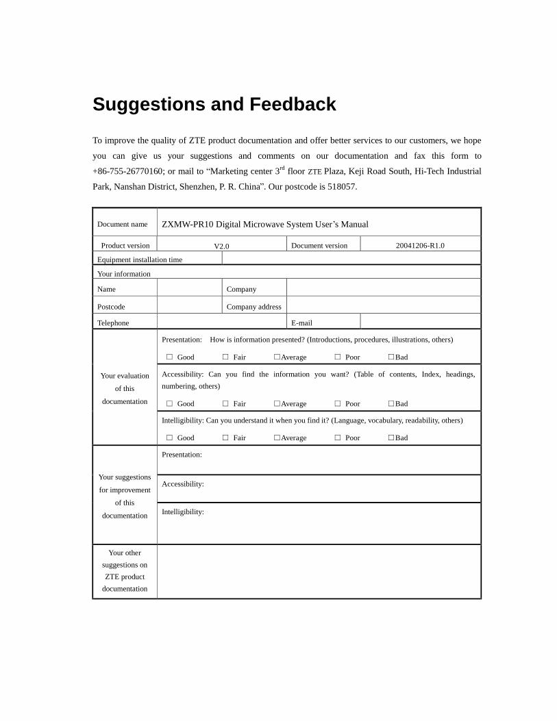
Suggestions and Feedback
To improve the quality of ZTE product documentation and offer better services to our customers, we hope
you can give us your suggestions and comments on our documentation and fax this form to
+86-755-26770160; or mail to “Marketing center 3rd floor ZTE Plaza, Keji Road South, Hi-Tech Industrial
Park, Nanshan District, Shenzhen, P. R. China”. Our postcode is 518057.
Document name ZXMW-PR10 Digital Microwave System User’s Manual
Product version V2.0 Document version 20041206-R1.0
Equipment installation time
Your information
Name Company
Postcode Company address
Telephone E-mail
Presentation: How is information presented? (Introductions, procedures, illustrations, others)
□ Good □ Fair □Average □ Poor □Bad
Accessibility: Can you find the information you want? (Table of contents, Index, headings, numbering, others)
□ Good □ Fair □Average □ Poor □Bad
Your evaluation
of this
documentation
Intelligibility: Can you understand it when you find it? (Language, vocabulary, readability, others)
□ Good □ Fair □Average □ Poor □Bad
Presentation:
Accessibility: Your suggestions
for improvement
of this
documentation Intelligibility:
Your other suggestions on ZTE product
documentation


- i -
Contents
1 DECLARATION OF CONFORMITY.................................................................................................... 1
2 FIRST AID FOR ELECTRICAL SHOCK AND SAFETY RULES..................................................... 2
2.1 FIRST AID FOR ELECTRICAL SHOCK ....................................................................................... 2
2.1.1 Artificial Respiration.............................................................................................................. 2
2.1.2 Treatment of Burns ................................................................................................................ 2
2.2 SAFETY RULES.............................................................................................................................. 4
3 PURPOSE AND STRUCTURE OF THE MANUAL............................................................................. 6
3.1 PURPOSE OF THE MANUAL........................................................................................................ 6
3.2 AUDIENCE BASIC KNOWLEDGE ............................................................................................... 6
3.3 STRUCTURE OF THE MANUAL.................................................................................................. 6
4 ABBREVIATION LIST ............................................................................................................................ 8
4.1 LIST OF ABBREVIATIONS............................................................................................................ 8
5 SYSTEM PRESENTATION................................................................................................................... 10
5.1 RADIO SYSTEM OVERVIEW ..................................................................................................... 10
5.1.1 General................................................................................................................................. 10
5.2 COMPLIANCE WITH INTERNATIONAL STANDARDS.......................................................... 10
5.3 APPLICATIONS............................................................................................................................. 10
5.4 SYSTEM ARCHITECTURE.......................................................................................................... 10
5.4.1 IDU ...................................................................................................................................... 11
5.4.2 ODU..................................................................................................................................... 11
5.5 MANAGEMENT SYSTEMS......................................................................................................... 11
5.5.1 Management Ports ............................................................................................................... 12
5.5.2 Protocols .............................................................................................................................. 12

- ii -
6 EQUIPMENT TECHNICAL SPECIFICATIONS................................................................................15
6.1 TECHNICAL SPECIFICATION.....................................................................................................15
7 CHARACTERISTICS OF THE INDOOR UNIT .................................................................................24
7.1 GENERAL ......................................................................................................................................24
7.2 TRIBUTARY INTERFACE ............................................................................................................24
7.2.1 2-Mbit/s Interface .................................................................................................................24
7.2.2 Ethernet Interface (Optional)................................................................................................25
7.3 SERVICE CHANNEL INTERFACE ..............................................................................................25
7.3.1 64-kbit/s Contra-Directional Interface E0 (Optional)...........................................................25
7.3.2 EDI Interface (Optional).......................................................................................................25
7.3.3 EOW Interface (Optional) ....................................................................................................25
7.3.4 Network Management Interface ...........................................................................................25
7.4 MODULATOR / DEMODULATOR...............................................................................................26
7.5 CABLE INTERFACE .....................................................................................................................26
7.6 AVAILABLE LOOPS......................................................................................................................26
8 DESCRIPTION OF THE INDOOR UNIT - PDH INTERFACES......................................................27
8.1 1+0/1+1 IDU VERSIONS...............................................................................................................27
8.1.1 Line Interface........................................................................................................................27
8.1.2 Radio Interface .....................................................................................................................28
8.1.3 Equipment Controller ...........................................................................................................30
8.2 IDU LOOPS ....................................................................................................................................30
8.2.1 Tributary Loop......................................................................................................................30
8.2.2 Baseband Unit Loop .............................................................................................................31
8.2.3 IDU Loop..............................................................................................................................31
9 CHARACTERISTICS OF THE OUTDOOR UNIT.............................................................................40
9.1 GENERAL ......................................................................................................................................40

- iii -
9.2 TECHNICAL SPECIFICATIONS.................................................................................................. 40
10 DESCRIPTION OF THE OUTDOOR UNIT ..................................................................................... 45
10.1 GENERAL.................................................................................................................................... 45
10.2 TRANSMIT SECTION ................................................................................................................ 45
10.3 RECEIVE SECTION.................................................................................................................... 46
10.4 CABLE INTERFACE................................................................................................................... 46
10.5 ATPC OPERATION...................................................................................................................... 46
10.6 1+1 Tx SYSTEM.......................................................................................................................... 47
10.7 POWER SUPPLY......................................................................................................................... 48
11 INSTALLATION AND PROCEDURES FOR ENSURING ELECTROMAGNETIC
COMPATIBILITY ..................................................................................................................................... 53
11.1 GENERAL.................................................................................................................................... 53
11.2 MECHANICAL INSTALLATION............................................................................................... 53
11.2.1 IDU Installation.................................................................................................................. 53
11.3 ELECTRICAL WIRING............................................................................................................... 53
11.4 GROUNDING CONNECTION.................................................................................................... 54
12 USER CONNECTIONS ........................................................................................................................ 55
12.1 CONNECTOR USE FOR 1+0/1+1 STANDARD VERSION...................................................... 55
12.2 STANDARD VERSION CONNECTORS ................................................................................... 56
13 INSTALLATION ONTO THE POLE OF THE ODU WITH SEPARATED ANTENNA............. 58
13.1 INSTALLATION KIT................................................................................................................... 58
13.2 REQUIRED TOOLS FOR MOUNTING (NOT SUPPLIED)...................................................... 59
13.3 INSTALLATION PROCEDURE.................................................................................................. 59
13.4 GROUNDING .............................................................................................................................. 61
14 INSTALLATION ONTO THE WALL OF THE ODU WITH SEPARATED ANTENNA............ 71

- iv -
14.1 INSTALLATION KIT ...................................................................................................................71
14.2 REQUIRED TOOLS FOR MOUNTING (NOT SUPPLIED) ......................................................71
14.3 INSTALLATION PROCEDURE ..................................................................................................71
14.4 GROUNDING...............................................................................................................................74
15 INSTALLATION ONTO THE POLE OF THE ODU WITH INTEGRATED ANTENNA...........82
15.1 FOREWORD.................................................................................................................................82
15.2 INSTALLATION KIT ...................................................................................................................82
15.3 REQUIRED TOOLS FOR MOUNTING (NOT SUPPLIED) ......................................................82
15.4 INSTALLATION PROCEDURE ..................................................................................................83
15.4.1 Installation onto the pole of the support system and the antenna .......................................83
15.4.2 Installation of ODU ............................................................................................................84
15.4.3 ODU installation.................................................................................................................85
15.5 ANTENNA AIMING.....................................................................................................................85
15.6 COMPATIBILITY.........................................................................................................................86
15.7 GROUNDING...............................................................................................................................86
16 LINE-UP OF THE RADIO HOP........................................................................................................104
16.1 LINE-UP OF THE RADIO HOP ................................................................................................104
16.1.1 Antenna alignment and received field measurement ........................................................104
16.1.2 Network element configuration ........................................................................................104
16.1.3 Radio Checks....................................................................................................................104
17 PERIODICAL CHECKS.....................................................................................................................106
17.1 GENERAL ..................................................................................................................................106
17.2 CHECKS TO BE CARRIED OUT .............................................................................................106
18 COMPOSITION OF THE INDOOR UNIT.......................................................................................107
18.1 GENERAL ..................................................................................................................................107
19 COMPOSITION OF OUTDOOR UNIT............................................................................................108

- v -
19.1 GENERAL.................................................................................................................................. 108

Chapter 1 DECLARATION OF CONFORMITY
- 1 -
1 DECLARATION OF CONFORMITY
ZTE Corporation declares that the products: • Digital radio relay system 7 GHz • Digital radio relay system 8 GHz • Digital radio relay system 11 GHz • Digital radio relay system 13 GHz • Digital radio relay system 15 GHz • Digital radio relay system 18 GHz • Digital radio relay system 23 GHz • Digital radio relay system 25 GHz • Digital radio relay system 28 GHz • Digital radio relay system 38 GHz
comply with the essential requirements of article 3 of the R&TTE Directive (1999/05/EC). The following standards apply:
• EN 60950:200 “Safety of information technology equipment”. • EN 301 489-4 V.1.3.1 (2002-8): “Electromagnetic compatibility and radio spectrum Matters
(ERM); Electromagnetic Compatibility (EMC) standard for radio equipment and services; Part 4. Specific conditions for fixed radio links and ancillary equipment and services”
• ETSI EN 301 751 V.1.1. (2002-12): “Fixed Radio Systems; Point-to point equipment and antennas; generic harmonized standard for point-to-point digital fixed radio systems and antennas covering the essential requirements under article 3.2 of the 1999/5/EC Directive”.

Chapter 2 FIRST AID FOR ELECTRICAL SHOCK AND SAFETY RULES
- 2 -
2 FIRST AID FOR ELECTRICAL SHOCK AND SAFETY RULES
2.1 FIRST AID FOR ELECTRICAL SHOCK Do not touch the patient with bare hands until the circuit has been opened. Open the circuit by switching off the line switches. If that is not possible protect yourself with dry material and free the patient from the conductor.
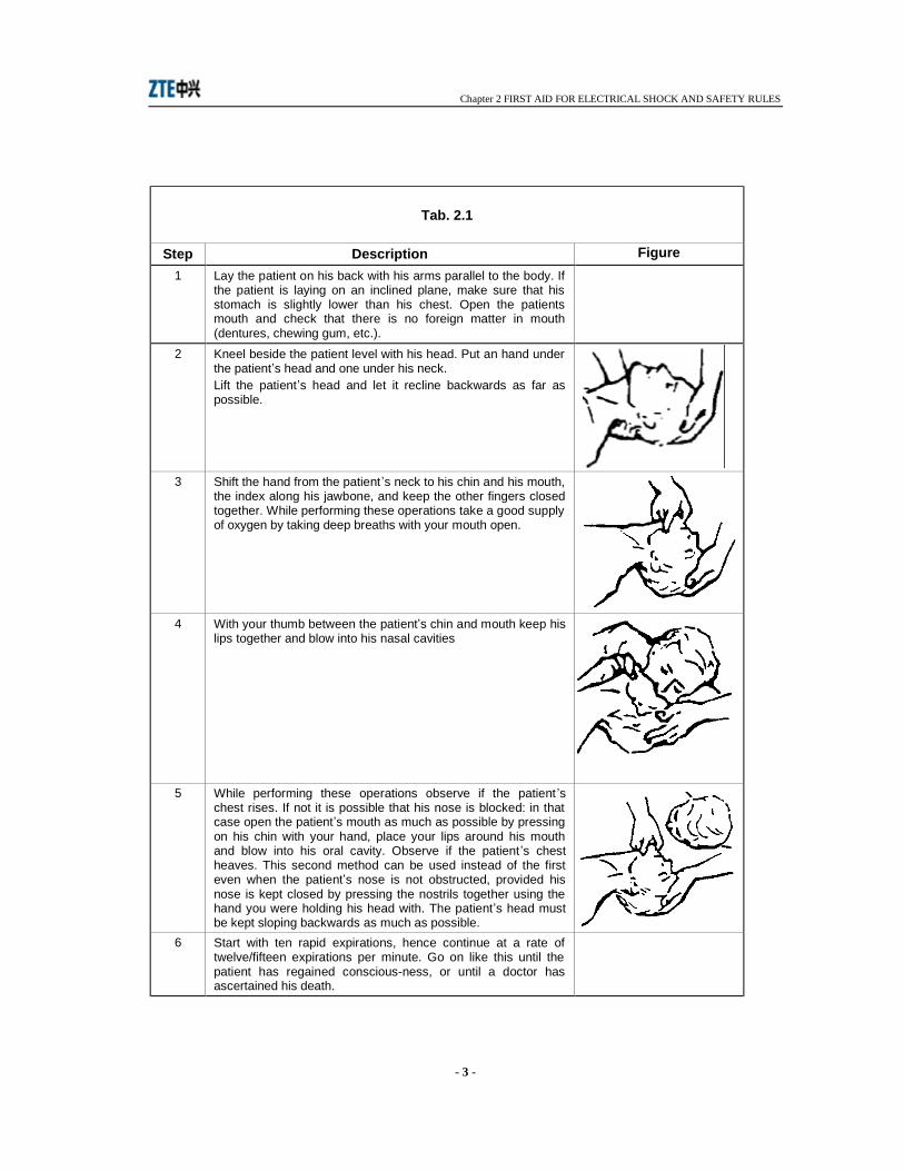
2.1.1 Artificial Respiration It is important to start mouth resuscitation at once and to call a doctor immediately. suggested procedure for mouth to mouth resuscitation method is described in the Tab. 2.1.
2.1.2 Treatment of Burns This treatment should be used after the patient has regained consciousness. It can also be employed while artificial respiration is being applied (in this case there should be at least two persons present).
Warning
• Do not attempt to remove clothing from burnt sections • Apply dry gauze on the burns • Do not apply ointments or other oily substances.
Chapter 2 FIRST AID FOR ELECTRICAL SHOCK AND SAFETY RULES
- 3 -
Tab. 2.1
Step Description Figure 1 Lay the patient on his back with his arms parallel to the body. If
the patient is laying on an inclined plane, make sure that his stomach is slightly lower than his chest. Open the patients mouth and check that there is no foreign matter in mouth (dentures, chewing gum, etc.).
2 Kneel beside the patient level with his head. Put an hand under the patient’s head and one under his neck. Lift the patient’s head and let it recline backwards as far as possible.
3 Shift the hand from the patient ’s neck to his chin and his mouth,
the index along his jawbone, and keep the other fingers closed together. While performing these operations take a good supply of oxygen by taking deep breaths with your mouth open.
4 With your thumb between the patient’s chin and mouth keep his lips together and blow into his nasal cavities
5 While performing these operations observe if the patient ’s chest rises. If not it is possible that his nose is blocked: in that case open the patient’s mouth as much as possible by pressing on his chin with your hand, place your lips around his mouth and blow into his oral cavity. Observe if the patient ’s chest heaves. This second method can be used instead of the first even when the patient’s nose is not obstructed, provided his nose is kept closed by pressing the nostrils together using the hand you were holding his head with. The patient’s head must be kept sloping backwards as much as possible.
6 Start with ten rapid expirations, hence continue at a rate of twelve/fifteen expirations per minute. Go on like this until the patient has regained conscious-ness, or until a doctor has ascertained his death.

Chapter 2 FIRST AID FOR ELECTRICAL SHOCK AND SAFETY RULES
- 4 -
2.2 SAFETY RULES When the equipment units are provided with the plate, shown in Fig. 2.1, it means that they contain components electrostatic charge sensitive.
In order to prevent the units from being damaged while handling, it is advisable to wear an elasticised band (Fig. 2.2) around the wrist ground connected through coiled cord (Fig. 2.3).
Fig. 2.1
Fig. 2.2
Fig. 2.3

Chapter 2 FIRST AID FOR ELECTRICAL SHOCK AND SAFETY RULES
- 5 -
The units showing the label, shown in Fig. 2.4, include laser diodes and the emitted power can be dangerous for eyes; avoid exposure in the direction of optical signal emission.
Fig. 2.4
Chapter 3 PURPOSE AND STRUCTURE OF THE MANUAL
- 6 -
3 PURPOSE AND STRUCTURE OF THE MANUAL
3.1 PURPOSE OF THE MANUAL The purpose of this manual consists in providing the user with information which allows to operate and maintain the ZXM-PR10 radio family. Warning: This manual does not include information relevant to the CIT-WEB management program windows and relevant application. They will provided by the CIT-WEB operation manual.
3.2 AUDIENCE BASIC KNOWLEDGE The following knowledge and skills are required to operate the equipment:
• a basic understanding of microwave transmission • installation and maintenance experience on digital radio system • a good knowledge of IP/OSI networks and routing policy.
3.3 STRUCTURE OF THE MANUAL The manual is subdivided into sections each of them developing a specific topic entitling the section. Each section consists of a set of chapters, enlarging the main subject master.
Section 1 - User Guide
It provides the information about the main safety rules and expounds the purpose and the structure of the manual.
Section 2 - Description and specifications
It traces the broad line of equipment operation and lists the main technical characteristics of the whole equipment and units it consists of. List of abbreviation meaning is also supplied.
Section 3 - Installation
The mechanical installation procedures are herein set down as well as the user electrical connections. The content of the tool kit (if supplied) is also listed.
Section 4 - Line-Up
Line-up procedures are described as well as checks to be carried out for the equipment correct operation. The list of the instruments to be used and their characteristics are also set down.
Chapter 3 PURPOSE AND STRUCTURE OF THE MANUAL
- 7 -
Section 5 - Maintenance
The routine maintenance actions are described as well as fault location procedures in order to identify the faulty unit and to re-establish the operation after its replacement with a spare one. Section 6 - Programming and supervision
The ZXMW-PR10 radio family is programmed and supervised using different software tools. Some of them are already available, some other will be available in the future. This section lists the tools implemented and indicates if descriptions are already available. Each description of software tools is supplied in a separated manual.
Section 7 - Composition Position, part numbers of the components the equipment consist of, are shown in this section.
Chapter 4 ABBREVIATION LIST
- 8 -
4 ABBREVIATION LIST
4.1 LIST OF ABBREVIATIONS - AIS Alarm Indication Signal - ATPC Automaric Transmit Power Control - BB Baseband - BBER Background Block Error Radio - BER Bit Error Rate - CIT Craft Interface Terminal - CU Core Unit - DSCP Differentiated Service Code Point - DSP Digital Signal Processing - EMC/EMI Electromagnetic Compatibility/Electromagnetic Interference - EOC Embedded Overhead Channel - EOW Engineering Orderwire - ESD Electrostatic Discharge - FEC Forward Error Corrector - FEM Fast Ethernet Module - FU Fan Unit - HDLC High Level Data Link Control - IDU Indoor Unit - IF Intermediate Frequency - LAN Local Area Network - LOF Loss Of Frame - LOS Loss Of Signal - MAC Media Access Control - MIB Management Information Base - MMIC Monolitic Microwave Integrated Circuit - MTBF Mean Time Between Failure - MU Modem Unit - NE Network Element - ODU Outdoor Unit - OSI Open System Interconnection - PDH Plesiochronous Digital Hierarchy - PPI Plesiochronous Physical Interface - PPP Point to Point Protocol - RIM Radio Interface Module - SNMP Simple Network Management Protocol - SU Service Unit - TCP/IP Transmission Control Protocol/Internet Protocol - VLAN Virtual LAN

Chapter 4 ABBREVIATION LIST
- 9 -
Chapter 5 SYSTEM PRESENTATION
- 10 -
5 SYSTEM PRESENTATION
5.1 RADIO SYSTEM OVERVIEW
5.1.1 General ZXMW PR10 (V3.2) Digital Microwave System is ZTE’s new PDH radio series for low-to-medium transmission capacities in frequency bands from 7 to 38 GHz. Different hardware versions offer a range of transmission capacities from 2xE1 to 16xE1, on QPSK and 16QAM modulation. Reduced cost, high reliability, compact size, light weight and full programmability are the key features of this radio series.
5.2 COMPLIANCE WITH INTERNATIONAL STANDARDS The equipment complies with the following international standards:
• EN 301 489-4 for EMC • ITU-R recommendations for all frequency bands • EN 300 132-2 characteristics for power supply • EN 300 019 environmental characteristics (Operation class 3.2 for IDU and class 4.1 for ODU;
storage: class 1.2; transport: class 2.3) • EN 60950 for safety
5.3 APPLICATIONS ZXMW PR10 main applications are:
• Radio communication between GSM/CDMA cells • Radio links for voice and data transmission • Spur routes for high capacity radio system • Emergency links
5.4 SYSTEM ARCHITECTURE The ZXMW PR10 radio series consists of two separate units:
• The indoor unit (IDU) that houses tributary interfaces, modem and controller units • The outdoor unit (ODU) that converts IF signals into RF signals and vice versa.
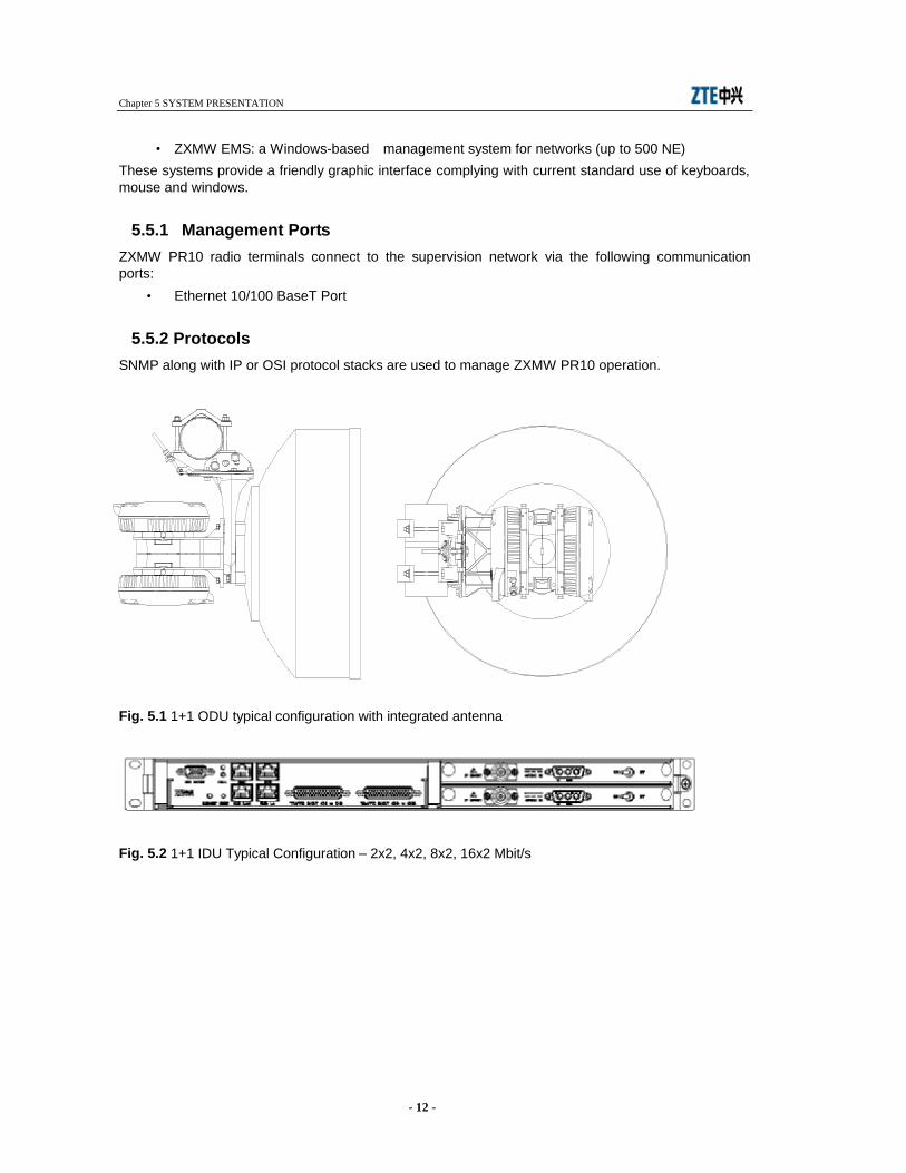
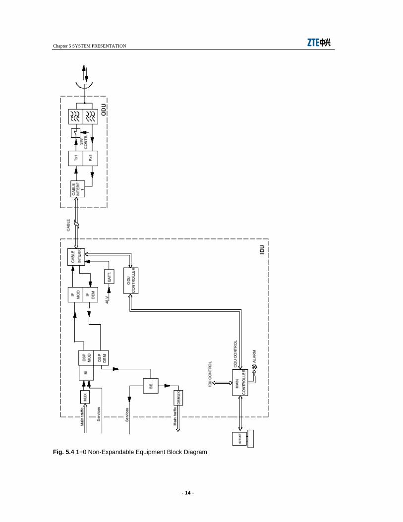
The two units are interconnected via coaxial cable. Fig. 5.1 and Fig. 5.2 show a typical IDU/ODU layout whereas Fig. 5.3 and Fig. 5.4 show the radio block diagram in 1+0 and 1+1 configuration respectively.
Chapter 5 SYSTEM PRESENTATION
- 11 -
5.4.1 IDU The IDU is available in the following hardware versions:
• 1 rack unit compact IDU, 1+0 configuration, 2/4/8xE1 • 1 rack unit compact IDU, 1+0 configuration, 2/4/8/16xE1 • 1 rack unit compact IDU, 1+1 configuration, 2/4/8/16xE1 • 1 rack unit compact IDU, 1+1 configuration, 2/4/8/16xE1
IDUs consist of two main units plugged into a 1-U cabinet.
Core Unit consisting of an integrated traffic interface module (TIM) for up to 16 E1/DS1 channels, room for an optionally plugged traffic interface module (TIM), room for an optionally plugged service interface module (SIM), a service multiplexer for service individual multiplexing/demultiplexing, a radio inter-working function for adaptation of the signals to the modem format, a radio protection switching function (RPS) to switch between two receive paths; a micro-controller.
Modem Unit consisting of a power supply, the digital modulator/demodulator and the conversion to and from an analogue intermediate frequency. In protected terminal configurations two identical Modem Units shall be present in the IDU. Line interfaces house tributary connections and, through a multiplexing/demultiplexing and bit insertion/extraction process, supply/receive the aggregate signal to/from the modulator/demodulator. Line interfaces carry out the digital processing for the QPSK/16QAM modulator and, in 1+1 configuration, duplicate the main signals on the transmission side and perform the changeover on the receive side. Interfaces towards the ODU house the cable interface for bidirectional communication between ODU and IDU, and implement the IF section of the mo-demodulator. IDU power supply units process battery voltage and supply power to IDU and ODU circuits. The controller section of the radio houses service channels interfaces, stores IDU firmware, interfaces ZTE management systems though dedicated supervision ports, and routes external and internal alarms to relay contacts.
5.4.2 ODU The ODU houses the interface towards the IDU on one side, and towards the antenna flange on the other. The ODU shifts the incoming QPSK/16QAM-modulated carrier to RF frequency through a double conversion. The opposite occurs at the receive side, when the IF-conevrted carrier is sent to the IDU demodulator. In 1+1 versions two electromechanical switches connect the transmitter in service to the antenna, and put in stand-by the other transmitter. Antenna coupling in 1+1 systems is done through a balanced or unbalanced hybrid.
5.5 MANAGEMENT SYSTEMS ZXMW PR10 can be controlled locally and remotely via ZTE supervision software:
• CIT-WEB: a ZTE’ proprietary software utility for monitoring and controlling the operation and configuration of the PR10 radios. Located on the PR10 Controller, any of the two LAN ports allows for connecting a PC running the CIT-WEB server that is embedded in the radio. This web server stores HTML pages and applets that provide a user interface for monitoring and controlling any PR10 Network Element, using the Microsoft Internet Explorer, version 5.5 and later.
Chapter 5 SYSTEM PRESENTATION
- 12 -
1+1 ODU typical configuration with integrated antenna
• ZXMW EMS: a Windows-based management system for networks (up to 500 NE) These systems provide a friendly graphic interface complying with current standard use of keyboards, mouse and windows.
5.5.1 Management Ports ZXMW PR10 radio terminals connect to the supervision network via the following communication ports:
• Ethernet 10/100 BaseT Port
5.5.2 Protocols SNMP along with IP or OSI protocol stacks are used to manage ZXMW PR10 operation.
Fig. 5.1 1+1 ODU typical configuration with integrated antenna
Fig. 5.2 1+1 IDU Typical Configuration – 2x2, 4x2, 8x2, 16x2 Mbit/s

Chapter 5 SYSTEM PRESENTATION
- 13 -
Fig. 5.3 1+1 Equipment Block Diagram
Chapter 5 SYSTEM PRESENTATION
- 14 -
Fig. 5.4 1+0 Non-Expandable Equipment Block Diagram
Chapter 6 EQUIPMENT TECHNICAL SPECIFICATIONS
- 15 -
6 EQUIPMENT TECHNICAL SPECIFICATIONS
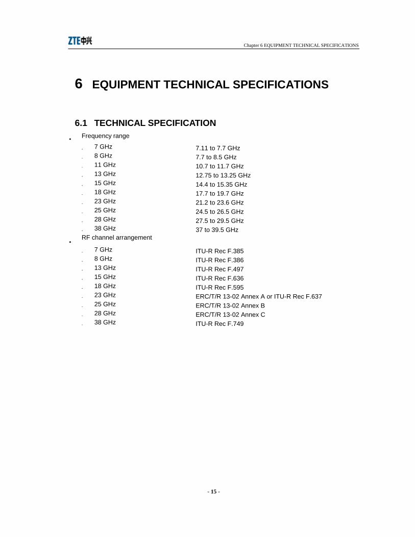
6.1 TECHNICAL SPECIFICATION •
- 7.11 to 7.7 GHz - 7.7 to 8.5 GHz - 10.7 to 11.7 GHz - 12.75 to 13.25 GHz - 14.4 to 15.35 GHz - 17.7 to 19.7 GHz - 21.2 to 23.6 GHz - 24.5 to 26.5 GHz - 27.5 to 29.5 GHz - 37 to 39.5 GHz
• - ITU-R Rec F.385 - ITU-R Rec F.386 - ITU-R Rec F.497 - ITU-R Rec F.636 - ITU-R Rec F.595 - ERC/T/R 13-02 Annex A or ITU-R Rec F.637 - ERC/T/R 13-02 Annex B - ERC/T/R 13-02 Annex C - ITU-R Rec F.749
Frequency range
7 GHz 8 GHz 11 GHz 13 GHz 15 GHz 18 GHz 23 GHz 25 GHz 28 GHz 38 GHz
RF channel arrangement
7 GHz 8 GHz 13 GHz 15 GHz 18 GHz 23 GHz 25 GHz 28 GHz 38 GHz

Chapter 6 EQUIPMENT TECHNICAL SPECIFICATIONS
- 16 -
• - 245/196/168/161 MHz - 311.32 MHz - 530 MHz - 266 MHz - 728 MHz - 1010 MHz - 1008 MHz - 1008 MHz - 1008 MHz - 1260 MHz
• Transmission capacity - Main signal from 2 to 16x2 Mbit/s
see Tab. 6.1
Tab. 6.1 Signal capacity from 2x2 up to 16x2 Mbit/s
Capacity (Mbit/s) Configuration Mechanical dimension 2x2/4x2/8x2/16x2 1+0 1 unit high 2x2/4x2/8x2/16x2 1+1 1 unit high
• The following service channel is available: • 1+0/1+1 standard - 2x2, 4x2, 8x2, 16x2 Mbit/s version (1 standard unit)
One of the following service channels is available: - 64 kbit/s E0 interface
• 1+0 or 1+1 hot stand-by and 1 antenna, 1+1 frequency diversity on 1 cross polar antenna or two separated antennas
• ± 5 ppm; ± 10 ppm ageing included
• according to ETSI EN 301 390
• QPSK/16QAM
Go-return frequency 7 GHz 8 GHz 11 GHz 13 GHz 15 GHz 18 GHz 23 GHz 25 GHz 28 GHz 38 GHz
Service channel capacity
Antenna configuration
Frequency accuracy
RF spurious emissions
Modulation
Chapter 6 EQUIPMENT TECHNICAL SPECIFICATIONS
- 17 -
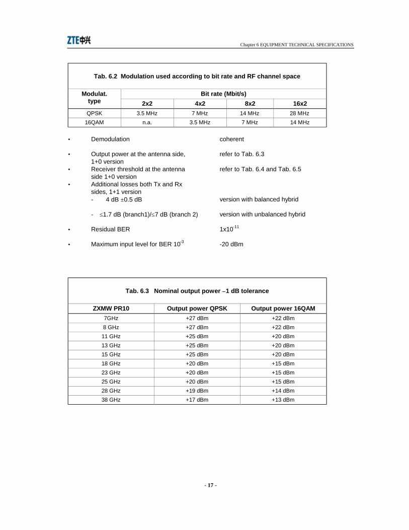
Tab. 6.2 Modulation used according to bit rate and RF channel space
Bit rate (Mbit/s) Modulat. type 2x2 4x2 8x2 16x2 QPSK 3.5 MHz 7 MHz 14 MHz 28 MHz
16QAM n.a. 3.5 MHz 7 MHz 14 MHz
• Demodulation coherent
• Output power at the antenna side, 1+0 version
refer to Tab. 6.3
• Receiver threshold at the antenna side 1+0 version
refer to Tab. 6.4 and Tab. 6.5
• Additional losses both Tx and Rx sides, 1+1 version
- 4 dB ±0.5 dB version with balanced hybrid
- ≤1.7 dB (branch1)/≤7 dB (branch 2) version with unbalanced hybrid
• Residual BER 1x10-11
• Maximum input level for BER 10-3 -20 dBm
Tab. 6.3 Nominal output power ±1 dB tolerance
ZXMW PR10 Output power QPSK Output power 16QAM 7GHz +27 dBm +22 dBm 8 GHz +27 dBm +22 dBm 11 GHz +25 dBm +20 dBm 13 GHz +25 dBm +20 dBm 15 GHz +25 dBm +20 dBm 18 GHz +20 dBm +15 dBm 23 GHz +20 dBm +15 dBm 25 GHz +20 dBm +15 dBm 28 GHz +19 dBm +14 dBm 38 GHz +17 dBm +13 dBm
Chapter 6 EQUIPMENT TECHNICAL SPECIFICATIONS
- 18 -
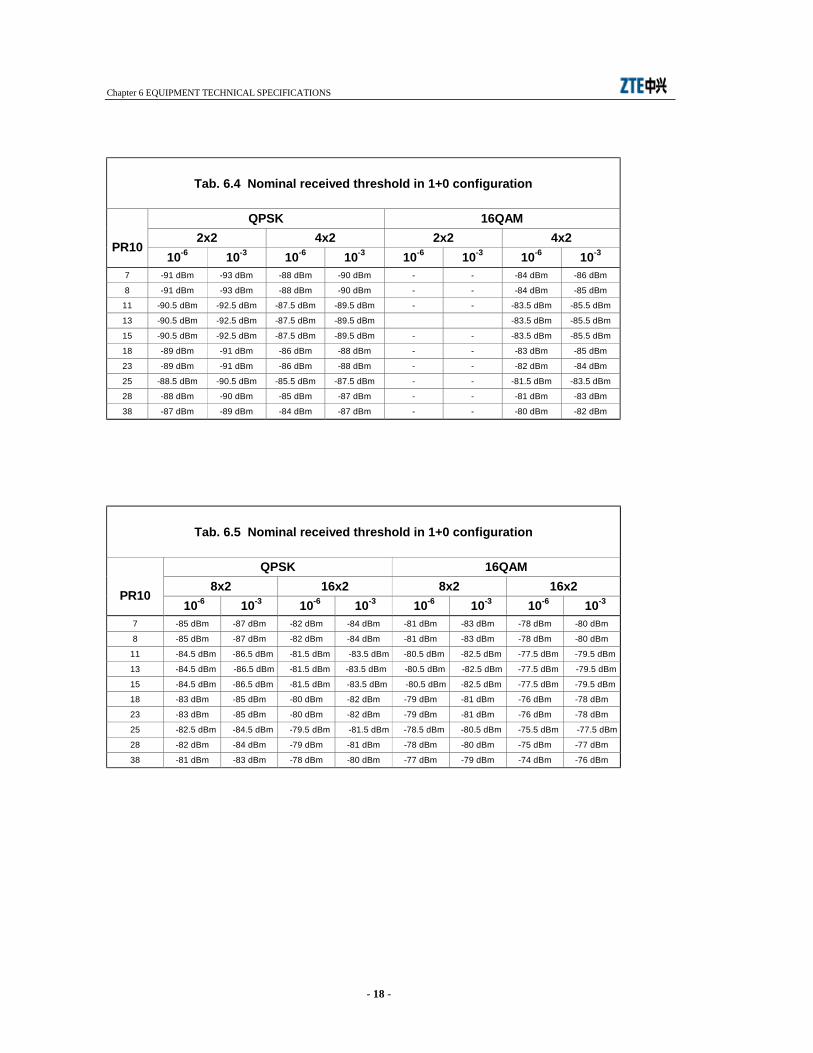
Tab. 6.4 Nominal received threshold in 1+0 configuration
QPSK 16QAM 2x2 4x2 2x2 4x2
PR10 10-6 10-3 10-6 10-3 10-6 10-3 10-6 10-3
7 -91 dBm -93 dBm -88 dBm -90 dBm - - -84 dBm -86 dBm
8 -91 dBm -93 dBm -88 dBm -90 dBm - - -84 dBm -85 dBm
11 -90.5 dBm -92.5 dBm -87.5 dBm -89.5 dBm - - -83.5 dBm -85.5 dBm
13 -90.5 dBm -92.5 dBm -87.5 dBm -89.5 dBm -83.5 dBm -85.5 dBm
15 -90.5 dBm -92.5 dBm -87.5 dBm -89.5 dBm - - -83.5 dBm -85.5 dBm
18 -89 dBm -91 dBm -86 dBm -88 dBm - - -83 dBm -85 dBm
23 -89 dBm -91 dBm -86 dBm -88 dBm - - -82 dBm -84 dBm
25 -88.5 dBm -90.5 dBm -85.5 dBm -87.5 dBm - - -81.5 dBm -83.5 dBm
28 -88 dBm -90 dBm -85 dBm -87 dBm - - -81 dBm -83 dBm
38 -87 dBm -89 dBm -84 dBm -87 dBm - - -80 dBm -82 dBm
Tab. 6.5 Nominal received threshold in 1+0 configuration
QPSK 16QAM 8x2 16x2 8x2 16x2
PR10 10-6 10-3 10-6 10-3 10-6 10-3 10-6 10-3
7 -85 dBm -87 dBm -82 dBm -84 dBm -81 dBm -83 dBm -78 dBm -80 dBm
8 -85 dBm -87 dBm -82 dBm -84 dBm -81 dBm -83 dBm -78 dBm -80 dBm
11 -84.5 dBm -86.5 dBm -81.5 dBm -83.5 dBm -80.5 dBm -82.5 dBm -77.5 dBm -79.5 dBm
13 -84.5 dBm -86.5 dBm -81.5 dBm -83.5 dBm -80.5 dBm -82.5 dBm -77.5 dBm -79.5 dBm
15 -84.5 dBm -86.5 dBm -81.5 dBm -83.5 dBm -80.5 dBm -82.5 dBm -77.5 dBm -79.5 dBm
18 -83 dBm -85 dBm -80 dBm -82 dBm -79 dBm -81 dBm -76 dBm -78 dBm
23 -83 dBm -85 dBm -80 dBm -82 dBm -79 dBm -81 dBm -76 dBm -78 dBm
25 -82.5 dBm -84.5 dBm -79.5 dBm -81.5 dBm -78.5 dBm -80.5 dBm -75.5 dBm -77.5 dBm
28 -82 dBm -84 dBm -79 dBm -81 dBm -78 dBm -80 dBm -75 dBm -77 dBm
38 -81 dBm -83 dBm -78 dBm -80 dBm -77 dBm -79 dBm -74 dBm -76 dBm

Chapter 6 EQUIPMENT TECHNICAL SPECIFICATIONS
- 19 -
• Power supply
- Power supply voltage
-40.8 to -57.6 Vdc
• Power consumption
Fully equipped terminal with 370 m 1/4” IDU-ODU cable.
Tab. 6.6
Configuration
Guaranteed power
consumption f≤15 GHz
-40.8 a -57.6 Vdc
Nominal Power Consumption
f≤15 GHz -48 Vdc
Guaranteed power
consumption f>15 GHz
-40.8 a -57.6 Vdc
Nominal Power Consumption
f>15 GHz -48 Vdc
1+0 ≤46 Watts ≤44 Watts ≤39 Watts ≤37 Watts 1+1 ≤70 Watts ≤66 Watts ≤58 Watts ≤54 Watts
•
Tab. 6.7
IDU type
Guaranteed consumption
f≤15 GHz -40.8 a -57.6 Vdc
Nominal Consumption
f≤15 GHz -48 Vdc
1+0 configuration ≤25 Watts ≤24 Watts
• Environmental conditions
- Operational range for IDU -5° C to +45° C - Operational range for ODU -33° C to +55° C
- Survival temperature range for IDU -10° C to +55° C - Survival temperature range for ODU -40° C to +60° C - Operational humidity for IDU 95% at +35° C - Operational humidity for ODU weather proof according to IP65
environmental class - Heat dissipation of ODU Thermal resistance 0.5° C/W
Solar heat gain: not exceeding 5° C - Wind load ≤260 Km/h • Mechanical characteristics
- Dimensions refer to Tab. 6.8
IDU only consumption
Chapter 6 EQUIPMENT TECHNICAL SPECIFICATIONS
- 20 -
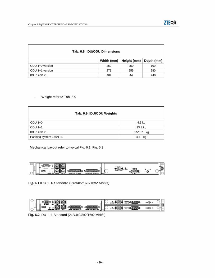
Tab. 6.8 IDU/ODU Dimensions
Width (mm) Height (mm) Depth (mm) ODU 1+0 version 250 250 100 ODU 1+1 version 278 255 280 IDU 1+0/1+1 482 44 240
- Weight refer to Tab. 6.9
Tab. 6.9 IDU/ODU Weights
ODU 1+0 4.5 kg ODU 1+1 13.3 kg IDU 1+0/1+1 3.5/3.7 kg Panning system 1+0/1+1 4.4 kg
- Mechanical Layout refer to typical Fig. 6.1, Fig. 6.2.
Fig. 6.1 IDU 1+0 Standard (2x2/4x2/8x2/16x2 Mbit/s)
Fig. 6.2 IDU 1+1 Standard (2x2/4x2/8x2/16x2 Mbit/s)
Chapter 6 EQUIPMENT TECHNICAL SPECIFICATIONS
- 21 -
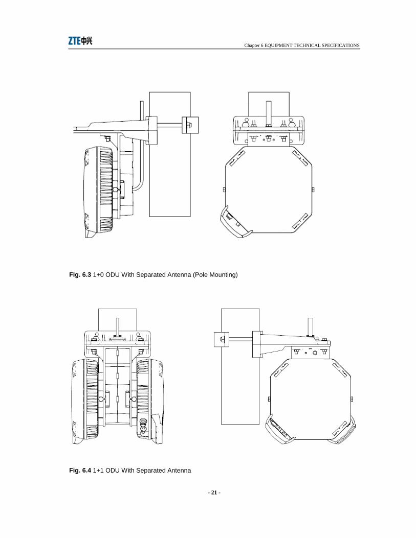
Fig. 6.3 1+0 ODU With Separated Antenna (Pole Mounting)
Fig. 6.4 1+1 ODU With Separated Antenna
Chapter 6 EQUIPMENT TECHNICAL SPECIFICATIONS
- 22 -
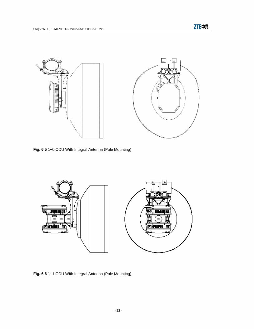
Fig. 6.5 1+0 ODU With Integral Antenna (Pole Mounting)
Fig. 6.6 1+1 ODU With Integral Antenna (Pole Mounting)
Chapter 6 EQUIPMENT TECHNICAL SPECIFICATIONS
- 23 -
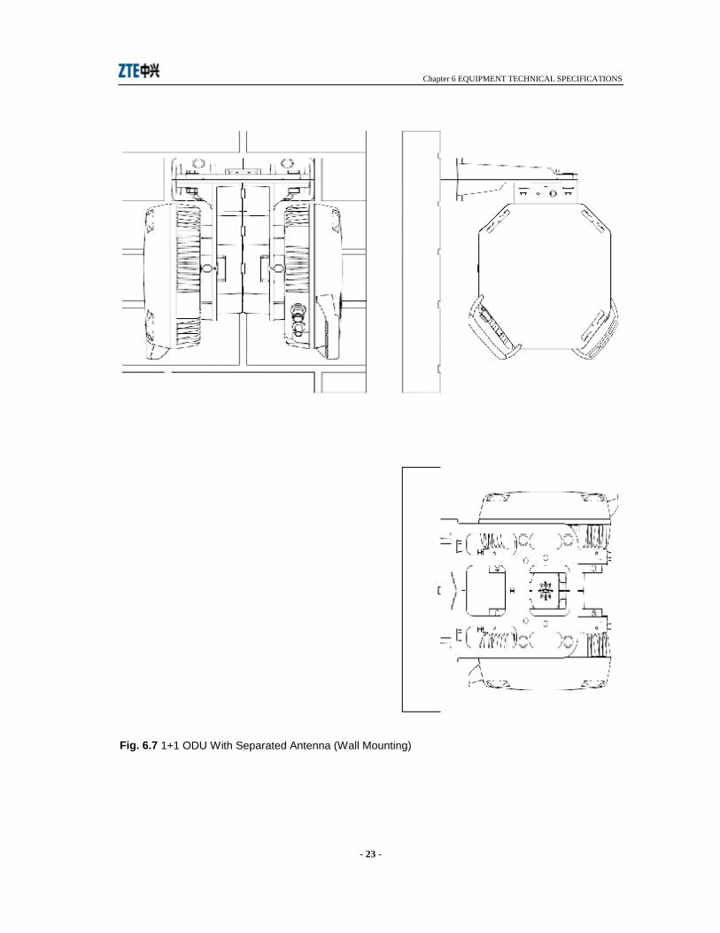
Fig. 6.7 1+1 ODU With Separated Antenna (Wall Mounting)
Chapter 7 CHARACTERISTICS OF THE INDOOR UNIT
- 24 -
7 CHARACTERISTICS OF THE INDOOR UNIT
7.1 GENERAL The following IDU characteristics are guaranteed for the temperature range from -5° C to +45° C.
7.2 TRIBUTARY INTERFACE
7.2.1 2-Mbit/s Interface
Input side
• 2048 kbit/s ±50 ppm
• HDB3
• 75 Ohm or 120 Ohm
• 2.37 Vp/75 Ohm or 3 Vp/120 Ohm
• 12 dB from 57 kHz to 102 kHz 18 dB from 102 kHz to 2048 kHz 14 dB from 2048 kHz to 3072 kHz
• 6 dB according to √f trend
• see mask in Table 2, ITU-T. G.823
• see mask in Figure 1, ITU-T. Rec. G.742
• SUB-D, 25 pins
Output side
• 2048 kbit/s ±50 ppm
• 75 Ohm or 120 Ohm
• 2.37 Vp/75 Ohm or 3 Vp/120 Ohm
• in accordance with G.742/G.823
• see mask in Figure 15, ITU-T G.703
• D-SUB, 44 pins
Bit rate
Line code
Rated impedance
Rated level
Return loss
Max attenuation of the input cable
Accepted jitter
Transfer function
Connector type
Bit rate
Rated impedance
Rated level
Output jitter
Pulse shape
Connector type
Chapter 7 CHARACTERISTICS OF THE INDOOR UNIT
- 25 -
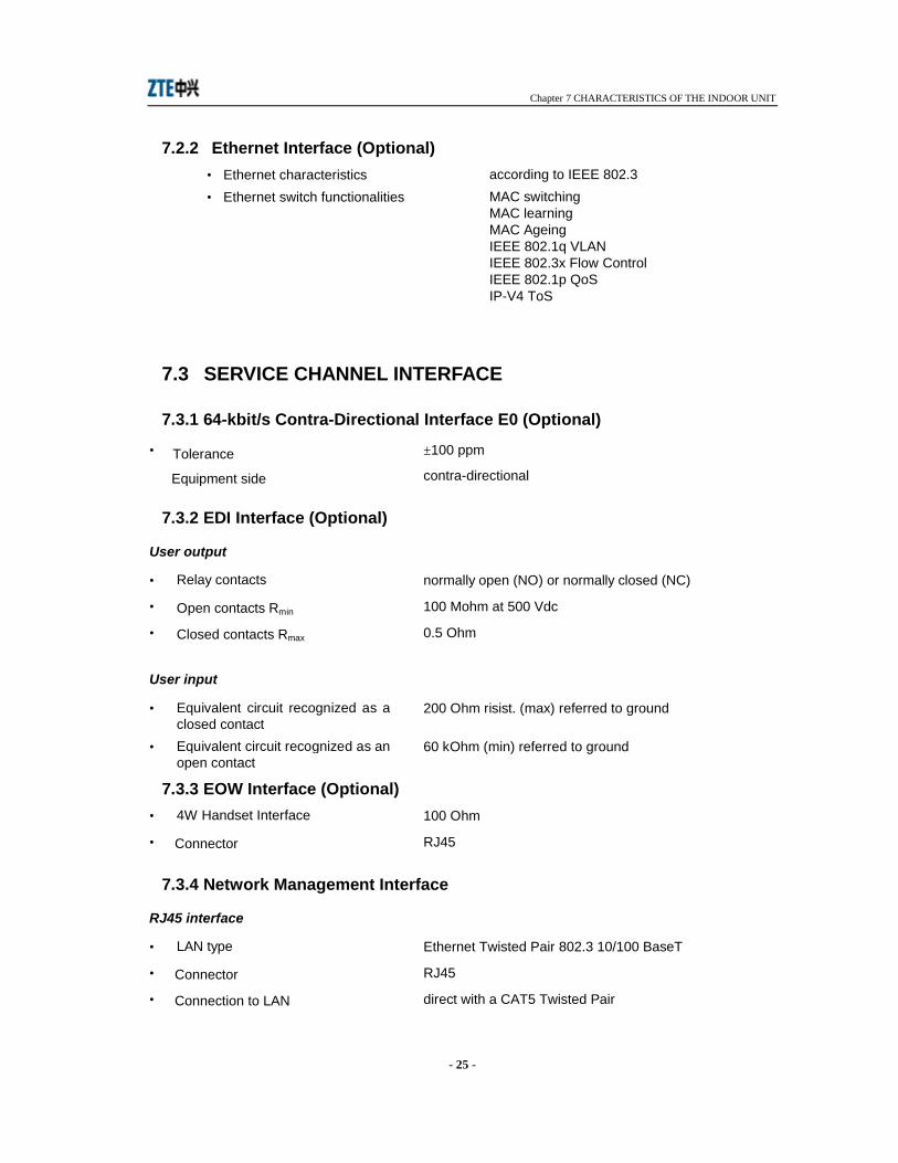
7.2.2 Ethernet Interface (Optional) • Ethernet characteristics according to IEEE 802.3
• Ethernet switch functionalities MAC switching MAC learning MAC Ageing IEEE 802.1q VLAN IEEE 802.3x Flow Control IEEE 802.1p QoS IP-V4 ToS
7.3 SERVICE CHANNEL INTERFACE
7.3.1 64-kbit/s Contra-Directional Interface E0 (Optional)
• ±100 ppm
contra-directional
7.3.2 EDI Interface (Optional)
User output
• normally open (NO) or normally closed (NC)
• 100 Mohm at 500 Vdc
• 0.5 Ohm
User input
• 200 Ohm risist. (max) referred to ground
• 60 kOhm (min) referred to ground
7.3.3 EOW Interface (Optional) • 100 Ohm
• RJ45
7.3.4 Network Management Interface
RJ45 interface
• Ethernet Twisted Pair 802.3 10/100 BaseT
• RJ45
• direct with a CAT5 Twisted Pair
Tolerance
Equipment side
Relay contacts
Open contacts Rmin
Closed contacts Rmax
Equivalent circuit recognized as a closed contact Equivalent circuit recognized as an open contact
LAN type
Connector
Connection to LAN
4W Handset Interface
Connector
Chapter 7 CHARACTERISTICS OF THE INDOOR UNIT
- 26 -
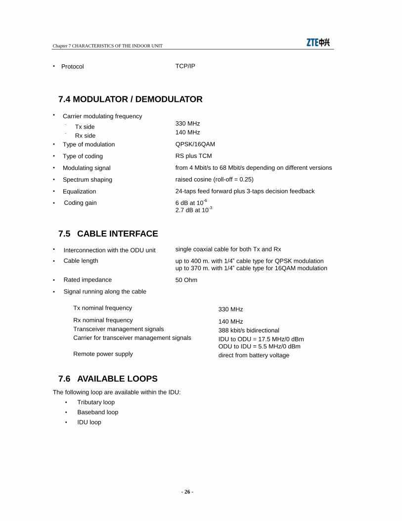
• TCP/IP
7.4 MODULATOR / DEMODULATOR •
- 330 MHz - 140 MHz
• QPSK/16QAM
• RS plus TCM
• from 4 Mbit/s to 68 Mbit/s depending on different versions
• raised cosine (roll-off = 0.25)
• 24-taps feed forward plus 3-taps decision feedback
• 6 dB at 10-6 2.7 dB at 10-3
7.5 CABLE INTERFACE • single coaxial cable for both Tx and Rx
• up to 400 m. with 1/4” cable type for QPSK modulation up to 370 m. with 1/4” cable type for 16QAM modulation
• 50 Ohm
•
Tx nominal frequency 330 MHz
Rx nominal frequency 140 MHz Transceiver management signals 388 kbit/s bidirectional Carrier for transceiver management signals IDU to ODU = 17.5 MHz/0 dBm
ODU to IDU = 5.5 MHz/0 dBm Remote power supply direct from battery voltage
7.6 AVAILABLE LOOPS The following loop are available within the IDU:
• Tributary loop • Baseband loop • IDU loop
Protocol
Carrier modulating frequency
Tx side Rx side
Type of modulation
Type of coding
Modulating signal
Spectrum shaping
Equalization
Coding gain
Interconnection with the ODU unit
Cable length
Rated impedance
Signal running along the cable

Chapter 8 DESCRIPTION OF THE INDOOR UNIT - PDH INTERFACES
- 27 -
8 DESCRIPTION OF THE INDOOR UNIT - PDH INTERFACES
8.1 1+0/1+1 IDU VERSIONS The following functional description covers the versions the IDU consists of as shown in chapter “Equipment technical specifications”. The IDU is made up of a backplane that equipped with plug in units - a core unit (CU) and a modem unit (MU). In protected terminal configurations two identical Modem Units shall be present in the IDU. CU is a motherboard that have room for an optionally plugged traffic unit (TU) up to 16 E1 channels and an optionally plugged service unit (SU) for EOW and EDI interface which realizing the following functionalities:
• Line interface • Equipment controller • IDU loops • Radio inter-working function for adaptation of the signals to the modem format • Radio protection switching function (RPS) to switch between two receive paths
Modem Unit consisting of a power supply, the digital modulator/demodulator and the conversion to and from an analogue intermediate frequency which realizing the following functionalities:
• Radio interface
8.1.1 Line Interface The line interface performs the following operations:
• multiplexing process of the input tributaries • generation of the aggregate frame by aggregating multiplexed tributaries and service
channel. Bit extraction and demultiplexing process happens at the receive side. Different baseband structures and digital processing of the signal to be forwarded to the QPSK or 16QAM modulator/demodulator is produced by a “chip set”. Controls to the chip set and status/alarm reporting from the chip set are given/received by main controller that manages the all equipment.
Tx side
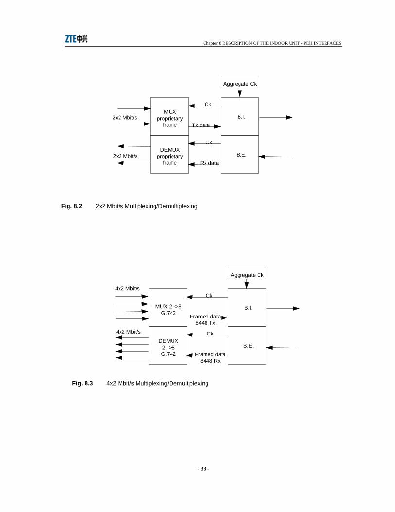
Refer to Fig. 8.1. The 2 Mbit/s input signal is code converted from HDB3 to NRZ format before being multiplexed. The multiplexing scheme depends on the number and the bit rate of the input tributaries. Attached figures show different multiplexing scheme as follows:
• Fig. 8.2 - 2x2 Mbit/s multiplexing. The mux performs stuffing operation on each single tributary and generates a proprietary frame embedding the two tributaries to be sent to the Bit Insertion. Opposite operation occurs at the Rx side.
• Fig. 8.3 - 4x2 Mbit/s multiplexing. The mux aggregates the four 2 Mbit/s tributaries generating a 8448 kbit/s frame as per Recc. G.742. The multiplexed signal is then sent to the Bit Insertion. Opposite operation occurs at the Rx side.

Chapter 8 DESCRIPTION OF THE INDOOR UNIT - PDH INTERFACES
- 28 -
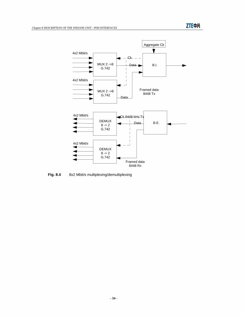
• Fig. 8.4 - 8x2 Mbit/s multiplexing. The eight 2 Mbit/s tributaries are grouped in two 4x2 Mbit/s groups each of one generating a G742 frame structure at 8448 kbit/s to be sent to the next Bit Insertion. Opposite operation occurs at the Rx side.
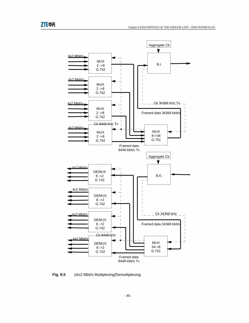
• Fig. 8.5 - 16x2 Mbit/s multiplexing. The sixteen 2 Mbit/s tributaries are grouped in four 4x2 Mbit/s groups each of one generating a G.742 frame structure at 8448 kbit/s. A further multiplexing of the achieved four 8448 kbit/s streams will generate a frame structure at 34368 kbit/s as per Recc. G.751. This latter is to be sent to the Bit Insertion. Opposite operation occurs at the Rx side.
The multiplexed tributaries are then sent to the B.I. for aggregate frame generation occurring at the following bit rate depending on various versions implemented:
Tab. 8.1
Version Aggregate frame 2x2 Mbit/s 4860 kbit/s 4x2 Mbit/s 9720 kbit/s 8x2 Mbit/s 19440 kbit/s 16x2 Mbit/s 38880 kbit/s
The aggregate frame contains: • the main signal from the MUX(s) • the framed service signal from the service interface • the EOC signals for supervision message propagation towards the remote terminal • the frame alignment word • the bits dedicated to the FEC.
Rx side
Refer to Fig. 8.6. At Rx side the Bit extraction separates the main multiplexed signal from the service signal and then after a proper demultiplexing process (opposite to that previously described at the Tx side) sends them to the output interfaces.
8.1.2 Radio Interface This functionaly provides the following:
• QPSK/16QAM modemodulation • power supply to IDU and ODU • telemetry IDU/ODU • cable interface
QPSK/16QAM Modemodulation - Modulation Side
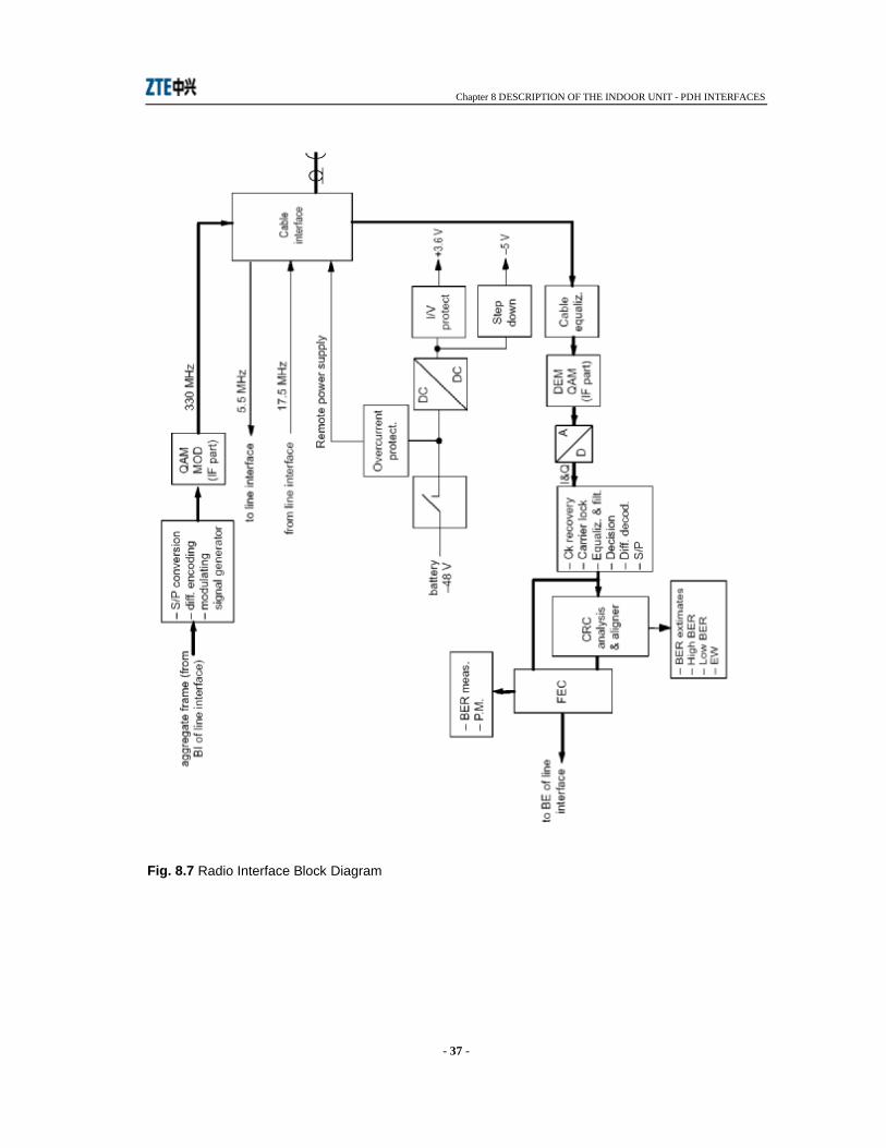
See Fig. 8.7. The aggregate signal from the BI undergoes the following process in digital form:

Chapter 8 DESCRIPTION OF THE INDOOR UNIT - PDH INTERFACES
- 29 -
• serial to parallel conversion • differential encoding • generation of the shaped modulating signals feeding the IF part of the QAM modulator.
This latter comprises: • recovery low pass filter to eliminate signal periodicity • 330 MHz local oscillator • a 90° phase shifter to supply two mixers with two in quadrature carriers
The thus obtained 330 MHz QAM modulated carrier is then sent to the cable interface for connection with ODU.
QAM Modemodulation - Demodulation Side
See Fig. 8.7. The 140 MHz, QPSK or 16QAM modulated carrier from the ODU is reaching the IDU through the cable interface. The connection to the demodulator input is made via a cable equalizer for cable loss compensation. The IF section of the QAM demodulator extracts the I and Q analogue signals then digital converted for the following processing:
• clock recovery • baseband equalisation and filtering • bit polarity decision • differential decoding • parallel to serial convertion to recover the aggregate signal.
The aggregate signal is then sent to a frame alignement circuit and CRC analysis and then to the error corrector to achieve the BER extimate, the PM and HBER/LBER alarms.
Power Supply
Refer to Fig. 8.7. The -48 V battery voltage feeds the IDU and ODU circuitry. The service voltages for the IDU feeding are achieved through a DC/DC converter for +3.3 V generation and a step down circuit for -5V. Both voltages are protected against overvoltages and overcurrents. The power to the ODU is given by the same battery running through the interconnection cable. A breaker protects the battery against cable failure.
Telemetry IDU/ODU
Refer to Fig. 8.1 and Fig. 8.7. The dialogue IDU/ODU is made-up by the main controller and associated peripherals within the ODU. Controls for ODU management and alarm reporting is performed making use of a 388 kbit/s framed signals. The transport along the interconneting cable is performed via two FSK modulated carriers: 17.5 MHz from IDU to ODU; 5.5 MHZ from ODU to IDU.
Cable Interface
Refer to Fig. 8.7. This circuit permits to communicate to the far ODU through the interconnecting cable. It is mainly made up of a set of filters that:
• combine the 330 MHz, QAM modulated carrier/the 17.5 MHz carrier/the power supply • separate the 140 MHz QAM modulated carrier and the 5.5 MHz carrier
Chapter 8 DESCRIPTION OF THE INDOOR UNIT - PDH INTERFACES
- 30 -
8.1.3 Equipment Controller The controller functionality performs the following:
• houses the equipment software for equipment management • interfaces the embedded CIT-WEB program through supervision ports • receive external alarms and route them to relay contacts along with the internal alarms
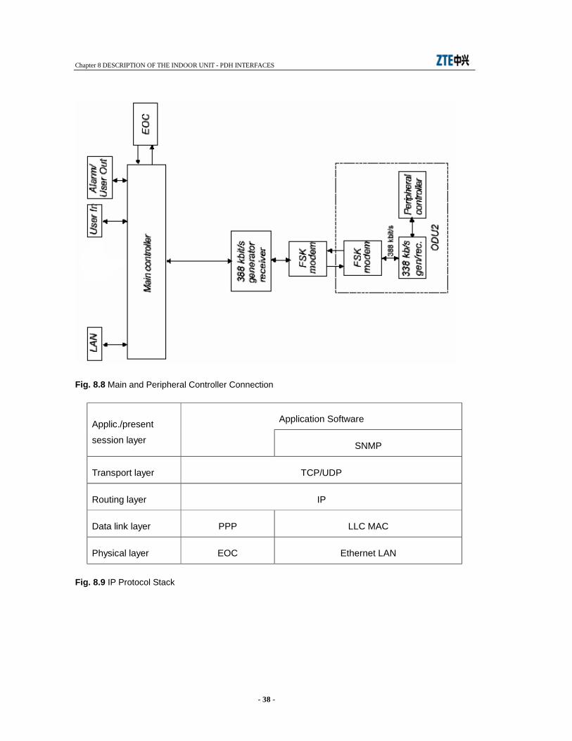
generated by the equipment. The equipment software permits to control and manage all the equipment functionality. It is distributed on two hardware levels: main controller and ODU peripheral controller. The dialogue between main and peripheral controllers is shown in Fig. 8.8. Main Controller
The activities executed by the main controller are the following: • Communication management: it makes use of SNMP as management protocol and IP as
communication protocol stacks. See Fig. 8.9 for details. The interface ports for the equipment management are the following: - LAN Ethernet 10/100BaseT used for CIT and NMS connection - EOC embedded within the PDH radio frame for connection to the remote NEs
• Log-in: the main controller manages the equipment or network login/logout by setting and then controlling the user’s ID and relevant password.
• Database (MIB): validation and storing in a non-volatile memory of the equipment configuration parameters.
• Equipment configuration: distribution of the parameters stored in the MIB towards the peripheral ∝Ps for their attuation in addition to the controls from user not stored in the MIB (i.e. loops, manual forcing etc...).
• alarm monitoring: acquisition, filtering and correlation of the alarms gathered from slaved ∝Ps. Local logger and alarm sending to the connected managers: CIT-WEB. Management of the alarm signalling on the front panel.
• Download: the main controller is equipped with two flash memory banks containing the running program (active bank) and the stand-by program (inactive bank). This permits to download a new software release to the inactive bank without distributing the traffic. Bank switch enables the new release to be used. Download activity is based on FTP protocol which downloads application programs, FPGA configuration, configuration files on main controller inactive bank or directly on the peripheral controllers.
Peripheral Controllers
The peripheral controllers take place within the ODU and are slaved to main controller with the task of activating controls and alarm reporting of dedicated functionality.
8.2 IDU LOOPS To control the IDU correct operation a set of local and remote loops are made available. The commands are forwarded by the CIT-WEB program. Loop block diagram is shown by Fig. 8.10.
8.2.1 Tributary Loop
Tributary Local Loop

Chapter 8 DESCRIPTION OF THE INDOOR UNIT - PDH INTERFACES
- 31 -
Each input tributary is routed directly to the trib. output upon receiving the command from the CIT. The Tx line transmission is still on.
Tributary Remote Loop
Each tributary directed towards the Rx output line is routed back to the Tx line. The Rx line is still on.
8.2.2 Baseband Unit Loop This kind of loop is only local and is activated at BI/BE level. The Tx line is still on.
8.2.3 IDU Loop This kind of loop permits to check the full IDU digital operation. When activated, the modulator output is connected to demodulator input.
Cod
e co
nver
ter
Cod
e co
nver
ter
MU
X
2x2/
4x2
8x2/
16x2
se
e Fi
g. 1
.2
thro
ugh
Fig.
1.
5
BI:
- mai
n tra
ffic
- ser
vice
s - E
OC
- F
EC
- F
AW
Fram
e ge
nera
tor
X0
38.8
8 M
Hz
nx2
NR
Z
CK
NR
Z
CK
- FS
K m
od/d
emod
- 3
88 fr
ame
ge
nera
tor/r
ecei
ver
to/fr
om m
ain
cont
rolle
r
Agg
rega
te fr
ame 5.
5 M
Hz
17.5
MH
z

Chapter 8 DESCRIPTION OF THE INDOOR UNIT - PDH INTERFACES
- 32 -
Fig. 8.1 Line Interface Block Diagram - Tx Side
Chapter 8 DESCRIPTION OF THE INDOOR UNIT - PDH INTERFACES
- 33 -
Fig. 8.2 2x2 Mbit/s Multiplexing/Demultiplexing
MUX proprietary
frame B.I.
DEMUX proprietary
frame B.E.
Ck
Ck
Tx data
Rx data
2x2 Mbit/s
2x2 Mbit/s
Aggregate Ck
Fig. 8.3 4x2 Mbit/s Multiplexing/Demultiplexing
MUX 2 ->8 G.742
B.I.
DEMUX 2 ->8 G.742
B.E.
Ck
Ck
Framed data 8448 Tx
Framed data 8448 Rx
4x2 Mbit/s
4x2 Mbit/s
Aggregate Ck
Chapter 8 DESCRIPTION OF THE INDOOR UNIT - PDH INTERFACES
- 34 -
Fig. 8.4 8x2 Mbit/s multiplexing/demultiplexing
MUX 2 ->8 G.742
B.I.
DEMUX 8 -> 2 G.742
B.E.
Ck 8448 kHz Tx
4x2 Mbit/s
4x2 Mbit/s
Aggregate Ck
MUX 2 ->8 G.742
Framed data 8448 Tx
4x2 Mbit/s
DEMUX 8 -> 2 G.742
4x2 Mbit/s
Framed data 8448 Rx
Ck
Data
Data
Data
Chapter 8 DESCRIPTION OF THE INDOOR UNIT - PDH INTERFACES
- 35 -
Fig. 8.5 16x2 Mbit/s Multiplexing/Demultiplexing
MUX 2 ->8 G.742
B.I.
4x2 Mbit/s
Aggregate Ck
MUX 2 ->8 G.742
4x2 Mbit/s
MUX 2 ->8 G.742
4x2 Mbit/s
MUX 2 ->8 G.742
4x2 Mbit/s MUX 8->34 G.751
Ck 8448 kHz Tx
Framed data 8448 kbit/s Tx
Framed data 34368 kbit/s
Ck 34368 kHz Tx
DEMUX 8 ->2 G.742
B.E.
4x2 Mbit/s
Aggregate Ck
DEMUX 8 ->2 G.742
4x2 Mbit/s
DEMUX 8 ->2 G.742
4x2 Mbit/s
DEMUX 8 ->2 G.742
4x2 Mbit/s MUX 34->8 G.751
Ck 8448 kHz
Framed data 8448 kbit/s Tx
Framed data 34368 kbit/s
Ck 34368 kHz

Chapter 8 DESCRIPTION OF THE INDOOR UNIT - PDH INTERFACES
- 36 -
Fig. 8.6 Line Interface Block Diagram (Rx Side)
from
dem
odul
ator
sid
e of
th
e ra
dio
inte
rface
BE
D
EM
UX
2/
2x2/
4x2
8x2/
16x2
See
Fig
. 8.2
th
roug
h Fi
g.
8.5
C
ode
Con
verte
r
C
ode
Con
verte
r
n x
2 M
bit/s
Chapter 8 DESCRIPTION OF THE INDOOR UNIT - PDH INTERFACES
- 37 -
Fig. 8.7 Radio Interface Block Diagram
Chapter 8 DESCRIPTION OF THE INDOOR UNIT - PDH INTERFACES
- 38 -
Fig. 8.8 Main and Peripheral Controller Connection
Application Software Applic./present
session layer SNMP
Transport layer TCP/UDP
Routing layer IP
Data link layer PPP LLC MAC
Physical layer EOC Ethernet LAN
Fig. 8.9 IP Protocol Stack

Chapter 8 DESCRIPTION OF THE INDOOR UNIT - PDH INTERFACES
- 39 -
Fig. 8.10 IDU Loopback
Chapter 9 CHARACTERISTICS OF THE OUTDOOR UNIT
- 40 -
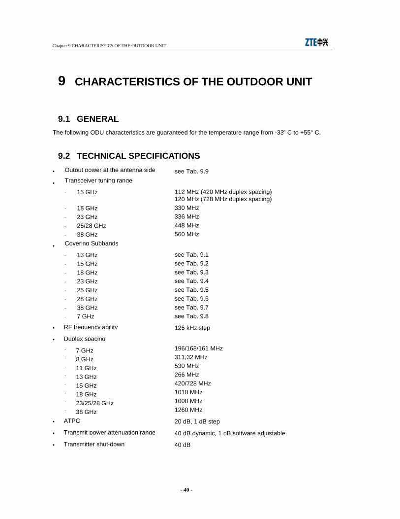
9 CHARACTERISTICS OF THE OUTDOOR UNIT
9.1 GENERAL The following ODU characteristics are guaranteed for the temperature range from -33° C to +55° C.
9.2 TECHNICAL SPECIFICATIONS • see Tab. 9.9
• - 112 MHz (420 MHz duplex spacing)
120 MHz (728 MHz duplex spacing) - 330 MHz - 336 MHz - 448 MHz - 560 MHz
• - see Tab. 9.1 - see Tab. 9.2 - see Tab. 9.3 - see Tab. 9.4 - see Tab. 9.5 - see Tab. 9.6 - see Tab. 9.7 - see Tab. 9.8
• 125 kHz step
• - 196/168/161 MHz - 311,32 MHz - 530 MHz - 266 MHz - 420/728 MHz - 1010 MHz - 1008 MHz - 1260 MHz
• 20 dB, 1 dB step
• 40 dB dynamic, 1 dB software adjustable
• 40 dB
Output power at the antenna side
Transceiver tuning range
15 GHz
18 GHz 23 GHz 25/28 GHz 38 GHz
Covering Subbands
13 GHz 15 GHz 18 GHz 23 GHz 25 GHz 28 GHz 38 GHz
RF frequency agility
Duplex spacing
7 GHz 8 GHz 11 GHz 13 GHz 15 GHz 18 GHz 23/25/28 GHz 38 GHz
ATPC
Transmit power attenuation range
Transmitter shut-down
7 GHz
Chapter 9 CHARACTERISTICS OF THE OUTDOOR UNIT
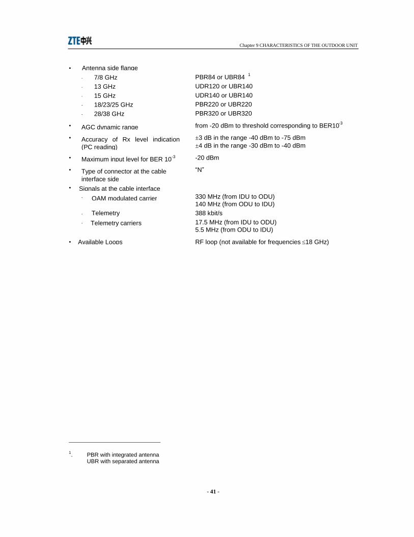
- 41 -
• - PBR84 or UBR84 1 - UDR120 or UBR140 - UDR140 or UBR140 - PBR220 or UBR220 - PBR320 or UBR320
• from -20 dBm to threshold corresponding to BER10-3
• ±3 dB in the range -40 dBm to -75 dBm ±4 dB in the range -30 dBm to -40 dBm
• -20 dBm
• “N”
• - 330 MHz (from IDU to ODU)
140 MHz (from ODU to IDU) - 388 kbit/s - 17.5 MHz (from IDU to ODU)
5.5 MHz (from ODU to IDU)
• RF loop (not available for frequencies ≤18 GHz)
1. PBR with integrated antenna
UBR with separated antenna
Antenna side flange 7/8 GHz 13 GHz 15 GHz 18/23/25 GHz 28/38 GHz
AGC dynamic range
Accuracy of Rx level indication (PC reading)
Maximum input level for BER 10-3
Type of connector at the cable interface side
Signals at the cable interface QAM modulated carrier
Telemetry Telemetry carriers
Available Loops
Chapter 9 CHARACTERISTICS OF THE OUTDOOR UNIT
- 42 -
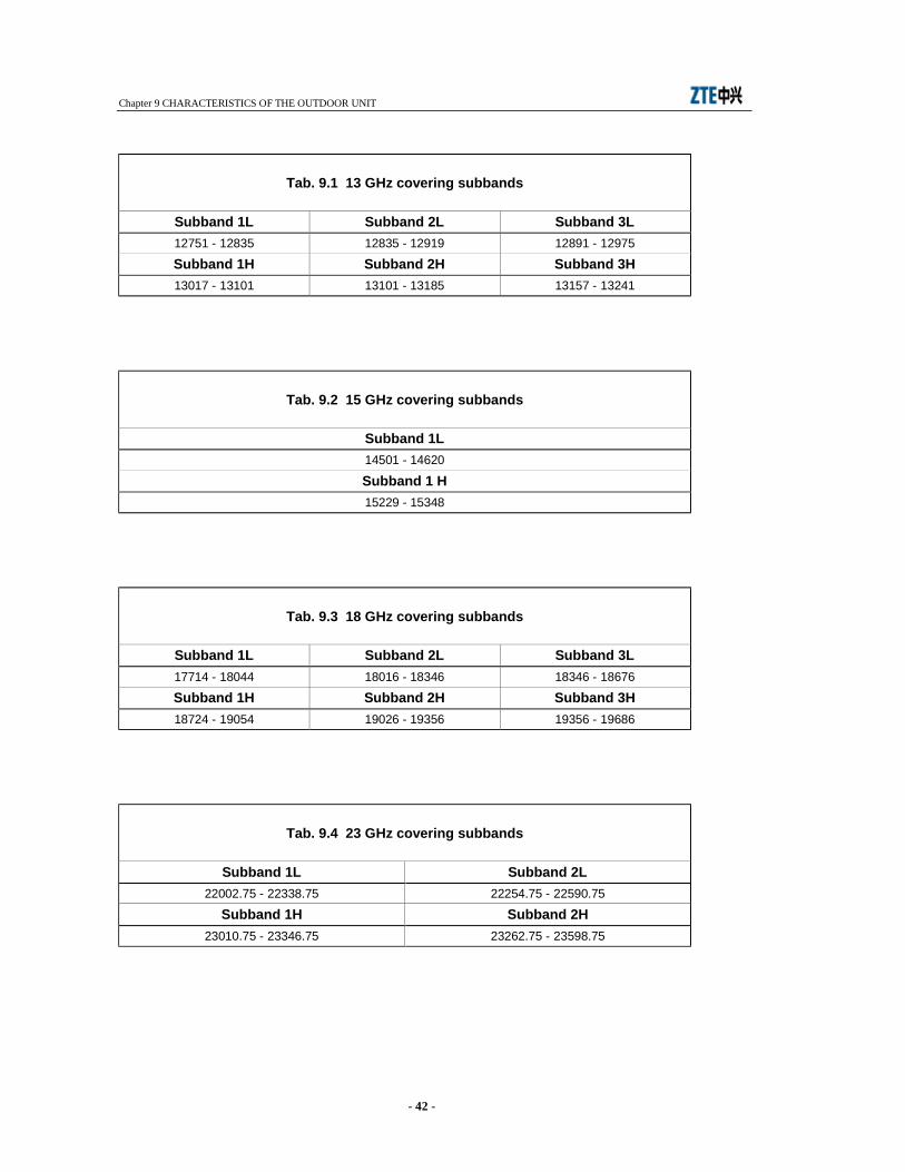
Tab. 9.1 13 GHz covering subbands
Subband 1L Subband 2L Subband 3L 12751 - 12835 12835 - 12919 12891 - 12975
Subband 1H Subband 2H Subband 3H 13017 - 13101 13101 - 13185 13157 - 13241
Tab. 9.2 15 GHz covering subbands
Subband 1L 14501 - 14620
Subband 1 H 15229 - 15348
Tab. 9.3 18 GHz covering subbands
Subband 1L Subband 2L Subband 3L 17714 - 18044 18016 - 18346 18346 - 18676
Subband 1H Subband 2H Subband 3H 18724 - 19054 19026 - 19356 19356 - 19686
Tab. 9.4 23 GHz covering subbands
Subband 1L Subband 2L 22002.75 - 22338.75 22254.75 - 22590.75
Subband 1H Subband 2H 23010.75 - 23346.75 23262.75 - 23598.75
Chapter 9 CHARACTERISTICS OF THE OUTDOOR UNIT
- 43 -
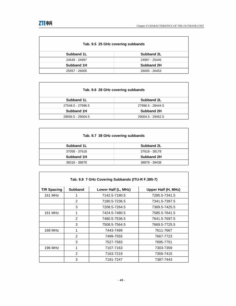
Tab. 9.5 25 GHz covering subbands
Subband 1L Subband 2L 24549 - 24997 24997 - 25445
Subband 1H Subband 2H 25557 - 26005 26005 - 26453
Tab. 9.6 28 GHz covering subbands
Subband 1L Subband 2L 27548.5 - 27996.5 27996.5 - 28444.5
Subband 1H Subband 2H 28556.5 - 29004.5 29004.5 - 29452.5
Tab. 9.7 38 GHz covering subbands
Subband 1L Subband 2L 37058 - 37618 37618 - 38178
Subband 1H Subband 2H 38318 - 38878 38878 - 39438
Tab. 9.8 7 GHz Covering Subbands (ITU-R F.385-7)
T/R Spacing Subband Lower Half (L, MHz) Upper Half (H, MHz) 161 MHz 1 7142.5-7180.5 7285.5-7341.5
2 7180.5-7236.5 7341.5-7397.5 3 7208.5-7264.5 7369.5-7425.5
161 MHz 1 7424.5-7480.5 7585.5-7641.5 2 7480.5-7536.5 7641.5-7697.5 3 7508.5-7564.5 7669.5-7725.5
168 MHz 1 7443-7499 7611-7667 2 7499-7555 7667-7723 3 7527-7583 7695-7751
196 MHz 1 7107-7163 7303-7359 2 7163-7219 7359-7415 3 7191-7247 7387-7443
Chapter 9 CHARACTERISTICS OF THE OUTDOOR UNIT
- 44 -
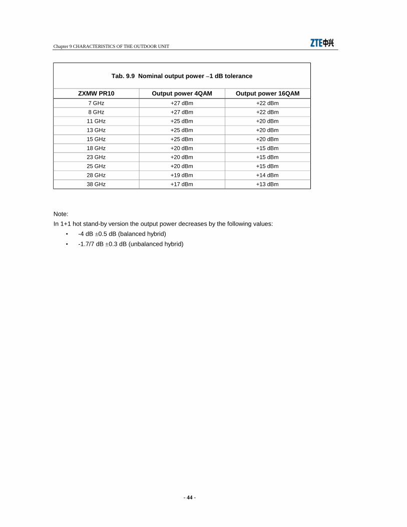
Tab. 9.9 Nominal output power ±1 dB tolerance
ZXMW PR10 Output power 4QAM Output power 16QAM 7 GHz +27 dBm +22 dBm 8 GHz +27 dBm +22 dBm
11 GHz +25 dBm +20 dBm 13 GHz +25 dBm +20 dBm 15 GHz +25 dBm +20 dBm 18 GHz +20 dBm +15 dBm 23 GHz +20 dBm +15 dBm 25 GHz +20 dBm +15 dBm 28 GHz +19 dBm +14 dBm 38 GHz +17 dBm +13 dBm
Note: In 1+1 hot stand-by version the output power decreases by the following values:
• -4 dB ±0.5 dB (balanced hybrid) • -1.7/7 dB ±0.3 dB (unbalanced hybrid)

Chapter 10 DESCRIPTION OF THE OUTDOOR UNIT
- 45 -
10 DESCRIPTION OF THE OUTDOOR UNIT
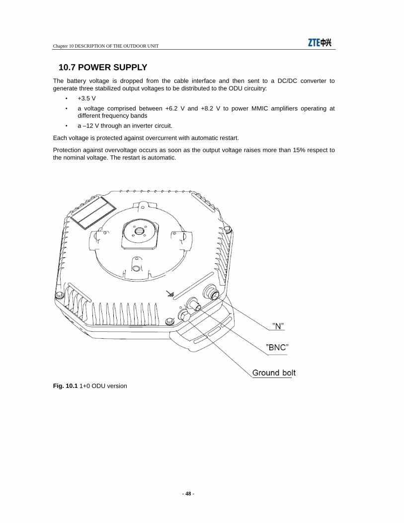
10.1 GENERAL The 1+0 ODU (refer to Fig. 10.1) consists of a two-shell aluminum mechanical structure, one shell housing all the ODU circuits, the other forming the covering plate. On the ODU are accessible:
• the “N” type connector for cable interfacing IDU and ODU • the “BNC” connector for connection to a multimeter with the purpose to measure the received
field strength • a ground bolt.
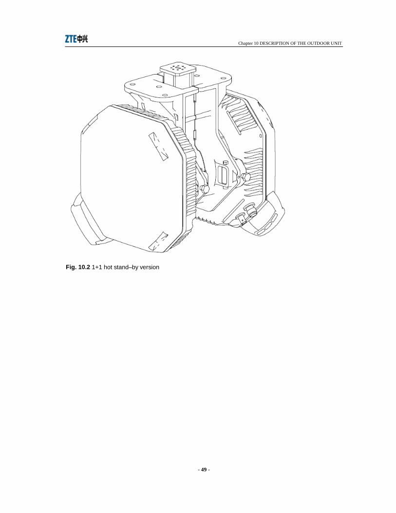
The 1+1 hot stand–by version (refer to Fig. 10.2) consist of two 1+0 ODUs mechanically secured to a structure housing the hybrid for the antenna connection.
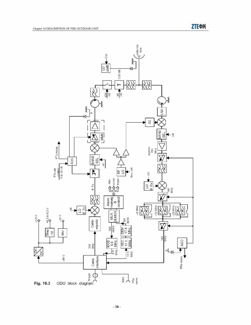
10.2 TRANSMIT SECTION Refer to block diagram shown in Fig. 10.3.
The 330 MHz QAM modulated carrier from the cable interface (see chapter 10.4) is forwarded to a mixer passing through a cable equalizer for cable loss compensation up to 40 dB at 330 MHz. The mixer and the following bandpass filter give rise to a second IF Tx carrier the frequency of which depends on the go/return frequency value. The mixer is of SHP type. The IF Tx frequency is µ P controlled. Same happens to Rx IF and RF local oscillators. This latter is common to both Tx and Rx sides.
The IF carrier is converted to RF and then amplified making use of a MMIC circuit. The conversion mixer is SSB type with side band selection.
The power at the MMIC output can be manually attenuated by 20 dB, 1 dB step. Total attenuation is 40 dB including the 20 dB attenuator that follows.
The automatic adjustment is performed making use of an ATPC (see paragraph 10.5 for details). The regulated output power is kept constant against amplifier stage gain variation by a feedback including the AGC.
Before reaching the antenna side the RF signal at the output of MMIC passes through the following circuits:
• a de-coupler plus detector diode to measure the output power • a circulator to protect the amplifier stages against possible circuit mismatch. • a ON/OFF switch for 1+1 operation • a 0 or 20 dB attenuator to made up a total attenuation of 40 dB • an RF band-pass filter for antenna coupling.
An RF coupler plus a detector and a shift oscillator made up the RF loop which is enabled upon receiving a µ P control. The RF loop permits the Tx power to return back to receive side thus controlling the total local radio terminal performance.
Chapter 10 DESCRIPTION OF THE OUTDOOR UNIT
- 46 -
10.3 RECEIVE SECTION The RF signal from the Rx bandpass filter is sent to a low noise amplifier that improves the receiver sensitivity.
The following down–converter translates the RF frequency to approximately 765 MHz. The conversion mixer is SSB type. The sideband selection is given through a μP control. A second down converter generates the 140 MHz IF carrier to be sent to the demodulator within the IDU. The level of the IF carrier is kept constant to –5 dBm thank to the IF amplifier stages, AGC controlled, distributed in the IF chain. In addition the AGC gives a measure of the receive RF level.
Between two amplifiers a bandpass filter assures the required selectivity to the receiver. The filter is SAW type and the bandwidth depends on the transmitted capacity as follows:
• ≈ 4 MHz (2x2 Mbit/s – QPSK; 4x2 Mbit/s – 16QAM) • ≈ 12 MHz (8x2/16x2 Mbit/s – 16QAM) • ≈ 28 MHz (16x2 Mbit/s – QPSK)
10.4 CABLE INTERFACE The cable interface permits to interface the cable interconnecting IDU to ODU and vice versa. It receives/transmits the following signals:
• 330 MHz (from IDU to ODU) • 140 MHz (from ODU to IDU) • 17.5 MHz (from IDU to ODU) • 5.5 MHz (from ODU to IDU) • remote power supply.
The 17.5 MHz and 5.5 MHz FSK modulated carriers, carry the telemetry channel. This latter consists of two 388 kbit/s streams one from IDU to ODU with the information to manage the ODU (RF power, RF frequency, capacity, etc...) while the other, from ODU to IDU, sends back to IDU measurements and alarms of the ODU. The ODU management is made by a μP.
10.5 ATPC OPERATION The ATPC regulates the RF output power of the local transmitter depending on the value of the RF level at the remote terminal. This value has to be preset from the local terminal as threshold high and low. The difference between the two thresholds must be equal or higher than 3 dB. As soon as the received level crosses the preset threshold level low (see Fig. 10.6) due to the increase of the hop attenuation, a microP at the received side of the remote terminal sends back to the local terminal a control to increase the transmitted power. The maximum ATPC range is 20 dB.
If the hop attenuation decreases and the threshold high is crossed then the control sent by the microP
causes the output power to decrease.
The 20 dB ATPC range can be reduced from the maximum value to 0 dB, by 1 dB step, consequently
to a reduction of the output maximum power through an adjusted attenuation. Total adjustment
attenuation is 40 dB formed by a variable attenuation part from 0 to 20 dB, 1 dB step and a fixed
attenuation part of 0 dB or 20 dB.

Chapter 10 DESCRIPTION OF THE OUTDOOR UNIT
- 47 -
ATPC behaves according the following example:
• maximum output power is +20 dBm: ATPC range is 20 dB • output power reduced from +20 dBm to 0 dBm, 1 dB step using the variable attenuation:
ATPC range is reduced from 20 dB to 0 dB consequently • reduction of output power from –1 dBm to –20 dBm, 1 dB step, using both fixed and variable
attenuation: ATPC range is reduced from 19 dB to 0 dB consequently.
10.6 1+1 Tx SYSTEM The two ODUs are coupled to the antenna side via a balanced or unbalanced hybrid. 1+1 Tx switching occurs in the 1+1 hot stand–by 1 antenna or 2 antennas versions as shown in Fig. 10.4 and Fig. 10.5.
The transmitter switchover is electromechanical type and consists of two ON/OFF switches within
the two ODUs that assure at least 40 dB insulation on the stand–by transmitter.
Transmit alarm priority is shown in Tab. 10.1.
Priority Levels Definition
Priority 1 RIM PSU Alarm
Priority 2 Manual forcing
Priority 3 Cable Short Alarm
Priority 3 Cable Open Alarm
Highest Priority 3 Modulator Failure
Priority 3 ODU Unit Failure Alarm
Priority 3 VCO Failure Alarm
Priority 3 IF Unit Alarm
Priority 3 ODU PSU Alarm
Priority 3 Tx Power Low Alarm
Priority 4 Request from remote terminal (both receivers
alarmed)
Lowest Priority 5 Revertive Tx (branch one preferential)
Chapter 10 DESCRIPTION OF THE OUTDOOR UNIT
- 48 -
10.7 POWER SUPPLY The battery voltage is dropped from the cable interface and then sent to a DC/DC converter to generate three stabilized output voltages to be distributed to the ODU circuitry:
• +3.5 V • a voltage comprised between +6.2 V and +8.2 V to power MMIC amplifiers operating at
different frequency bands • a –12 V through an inverter circuit.
Each voltage is protected against overcurrent with automatic restart.
Protection against overvoltage occurs as soon as the output voltage raises more than 15% respect to the nominal voltage. The restart is automatic.
Fig. 10.1 1+0 ODU version
Chapter 10 DESCRIPTION OF THE OUTDOOR UNIT
- 49 -
Fig. 10.2 1+1 hot stand–by version
Chapter 10 DESCRIPTION OF THE OUTDOOR UNIT
- 50 -

Chapter 10 DESCRIPTION OF THE OUTDOOR UNIT
- 51 -
Fig. 10.4 1+1 hot stand–by 1 antenna
Fig. 10.5 1+1 hot stand–by 2 antennas

Chapter 10 DESCRIPTION OF THE OUTDOOR UNIT
- 52 -
Fig. 10.6 ATPC operation
Chapter 11 INSTALLATION AND PROCEDURES FOR ENSURING ELECTROMAGNETIC COMPATIBILITY
- 53 -
11 INSTALLATION AND PROCEDURES FOR ENSURING ELECTROMAGNETIC COMPATIBILITY
11.1 GENERAL The equipment consists of IDU and ODU(s) units and is mechanically made up of a wired 19” subrack (IDU) and a weather proof metallic container (ODU). The two units are shipped together in an appropriate cardboard box. After unpacking, mechanical installation takes place followed by electrical connections as described in the following paragraphs.
11.2 MECHANICAL INSTALLATION
11.2.1 IDU Installation The front side of the IDU mechanical structure is provided with holes at the sides. This allows to fasten the subrack to a 19” rack by means of four M6 screws. If two or more IDUs are to be mounted, leave at least 1/2 rack unit space (22 mm) between two IDUs to avoid overheating problems.
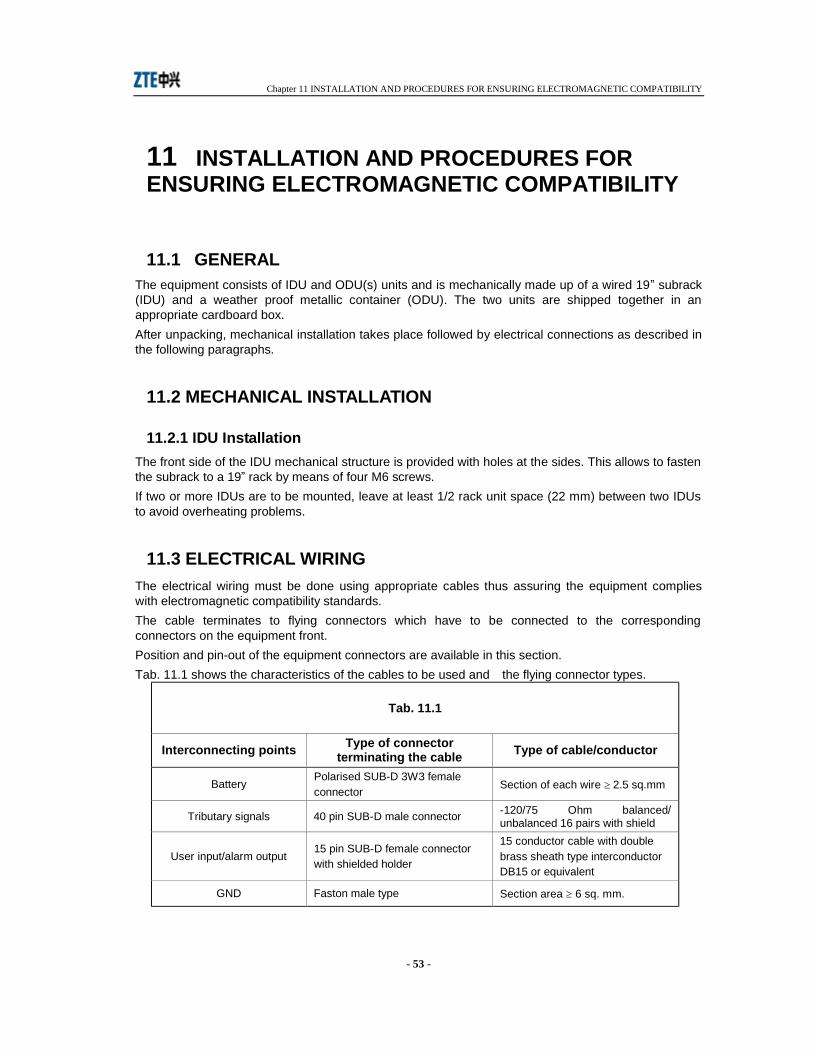
11.3 ELECTRICAL WIRING The electrical wiring must be done using appropriate cables thus assuring the equipment complies with electromagnetic compatibility standards. The cable terminates to flying connectors which have to be connected to the corresponding connectors on the equipment front. Position and pin-out of the equipment connectors are available in this section. Tab. 11.1 shows the characteristics of the cables to be used and the flying connector types.
Tab. 11.1
Interconnecting points Type of connector terminating the cable Type of cable/conductor
Battery Polarised SUB-D 3W3 female connector Section of each wire ≥ 2.5 sq.mm
Tributary signals 40 pin SUB-D male connector -120/75 Ohm balanced/ unbalanced 16 pairs with shield
User input/alarm output 15 pin SUB-D female connector with shielded holder
15 conductor cable with double brass sheath type interconductor DB15 or equivalent
GND Faston male type Section area ≥ 6 sq. mm.
Chapter 11 INSTALLATION AND PROCEDURES FOR ENSURING ELECTROMAGNETIC COMPATIBILITY
- 54 -
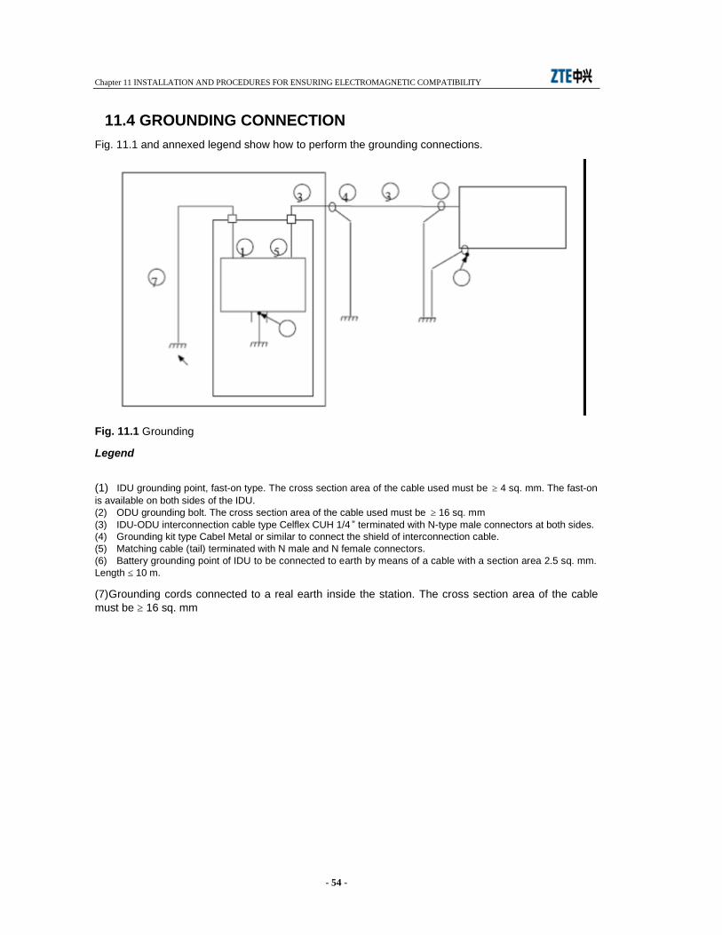
11.4 GROUNDING CONNECTION Fig. 11.1 and annexed legend show how to perform the grounding connections.
Fig. 11.1 Grounding
Legend
(1) IDU grounding point, fast-on type. The cross section area of the cable used must be ≥ 4 sq. mm. The fast-on is available on both sides of the IDU. (2) ODU grounding bolt. The cross section area of the cable used must be ≥ 16 sq. mm (3) IDU-ODU interconnection cable type Celflex CUH 1/4 ” terminated with N-type male connectors at both sides. (4) Grounding kit type Cabel Metal or similar to connect the shield of interconnection cable. (5) Matching cable (tail) terminated with N male and N female connectors. (6) Battery grounding point of IDU to be connected to earth by means of a cable with a section area 2.5 sq. mm. Length ≤ 10 m.
(7) Grounding cords connected to a real earth inside the station. The cross section area of the cable must be ≥ 16 sq. mm
Chapter 12 USER CONNECTIONS
- 55 -
12 USER CONNECTIONS
12.1 CONNECTOR USE FOR 1+0/1+1 STANDARD VERSION User connections are performed through connectors on the IDU front panel modules. The connectors are the following:
− Trib IN/OUT: 75 or 120 25-pin SUB-D male connector. For SUB-D connector details Tab. 12.1.
− NMS LA: RJ45 connector. Connector details refer to Tab. 12.2. − NMS LAN: RJ45 connector. Connector details refer to Tab. 12.2. − 50 Ohm connector for interconnection to ODU − 3 pin SUB-D connector for interconnection to battery. − EDI: 15-pin SUB-D male connector refer to Tab. 12.3 − RJ45 EOW connector.
Chapter 12 USER CONNECTIONS
- 56 -
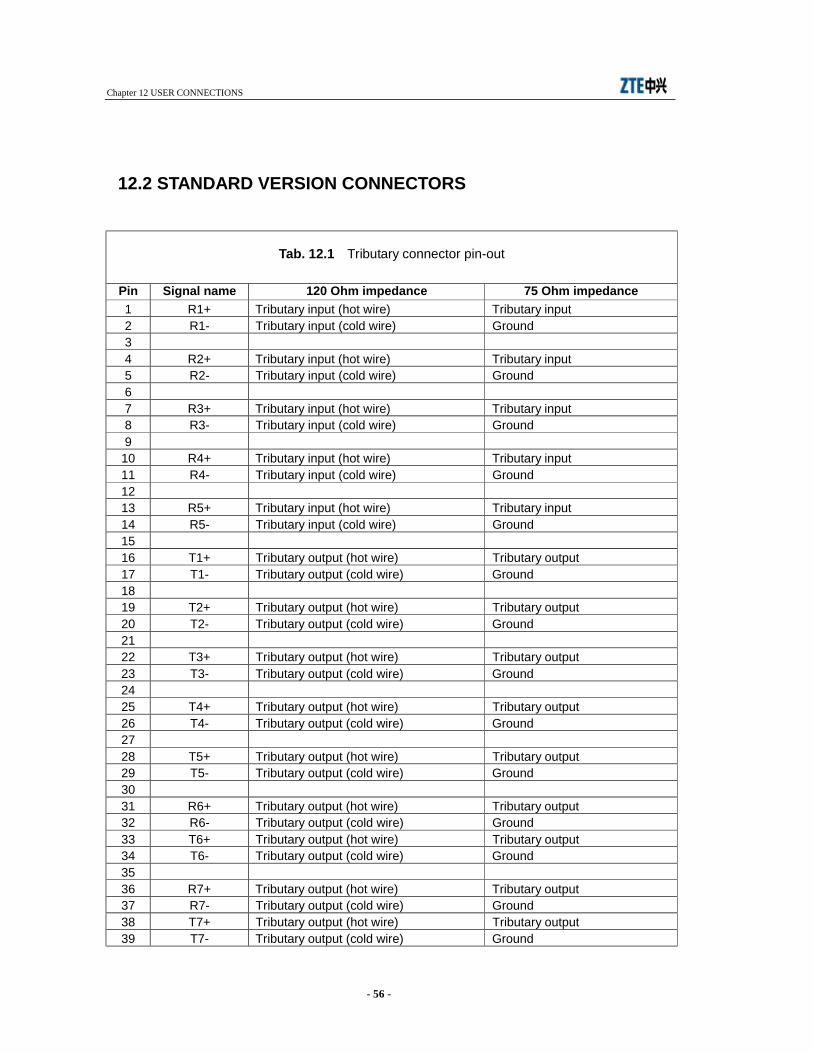
12.2 STANDARD VERSION CONNECTORS
Tab. 12.1 Tributary connector pin-out
Pin Signal name 120 Ohm impedance 75 Ohm impedance 1 R1+ Tributary input (hot wire) Tributary input 2 R1- Tributary input (cold wire) Ground 3 4 R2+ Tributary input (hot wire) Tributary input 5 R2- Tributary input (cold wire) Ground 6 7 R3+ Tributary input (hot wire) Tributary input 8 R3- Tributary input (cold wire) Ground 9
10 R4+ Tributary input (hot wire) Tributary input 11 R4- Tributary input (cold wire) Ground 12 13 R5+ Tributary input (hot wire) Tributary input 14 R5- Tributary input (cold wire) Ground 15 16 T1+ Tributary output (hot wire) Tributary output 17 T1- Tributary output (cold wire) Ground 18 19 T2+ Tributary output (hot wire) Tributary output 20 T2- Tributary output (cold wire) Ground 21 22 T3+ Tributary output (hot wire) Tributary output 23 T3- Tributary output (cold wire) Ground 24 25 T4+ Tributary output (hot wire) Tributary output 26 T4- Tributary output (cold wire) Ground 27 28 T5+ Tributary output (hot wire) Tributary output 29 T5- Tributary output (cold wire) Ground 30 31 R6+ Tributary output (hot wire) Tributary output 32 R6- Tributary output (cold wire) Ground 33 T6+ Tributary output (hot wire) Tributary output 34 T6- Tributary output (cold wire) Ground 35 36 R7+ Tributary output (hot wire) Tributary output 37 R7- Tributary output (cold wire) Ground 38 T7+ Tributary output (hot wire) Tributary output 39 T7- Tributary output (cold wire) Ground
Chapter 12 USER CONNECTIONS
- 57 -
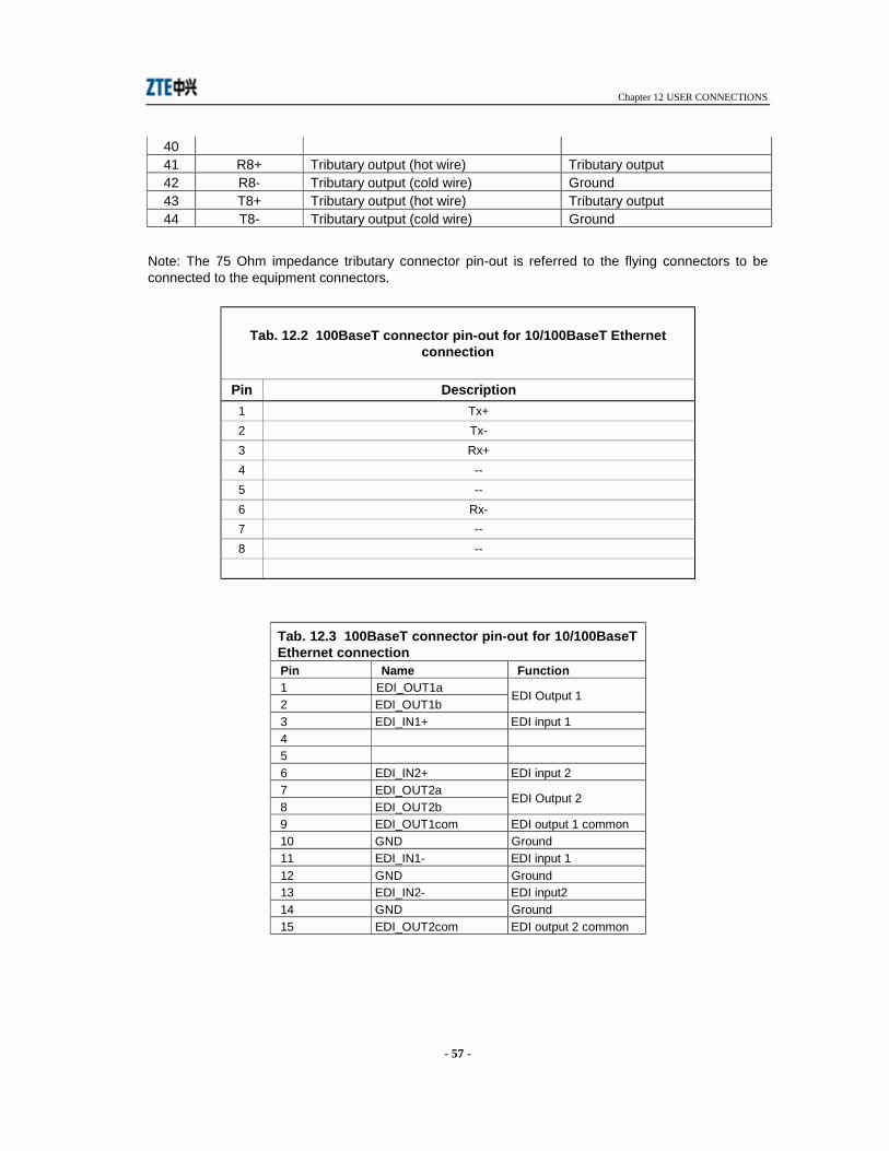
40 41 R8+ Tributary output (hot wire) Tributary output 42 R8- Tributary output (cold wire) Ground 43 T8+ Tributary output (hot wire) Tributary output 44 T8- Tributary output (cold wire) Ground
Note: The 75 Ohm impedance tributary connector pin-out is referred to the flying connectors to be connected to the equipment connectors.
Tab. 12.2 100BaseT connector pin-out for 10/100BaseT Ethernet connection
Pin Description 1 Tx+ 2 Tx- 3 Rx+ 4 -- 5 -- 6 Rx- 7 -- 8 --
Tab. 12.3 100BaseT connector pin-out for 10/100BaseT Ethernet connection Pin Name Function 1 EDI_OUT1a 2 EDI_OUT1b
EDI Output 1
3 EDI_IN1+ EDI input 1 4 5 6 EDI_IN2+ EDI input 2 7 EDI_OUT2a 8 EDI_OUT2b
EDI Output 2
9 EDI_OUT1com EDI output 1 common 10 GND Ground 11 EDI_IN1- EDI input 1 12 GND Ground 13 EDI_IN2- EDI input2 14 GND Ground 15 EDI_OUT2com EDI output 2 common
Chapter 13 INSTALLATION ONTO THE POLE OF THE ODU WITH SEPARATED ANTENNA
- 58 -
13 INSTALLATION ONTO THE POLE OF THE ODU WITH SEPARATED ANTENNA
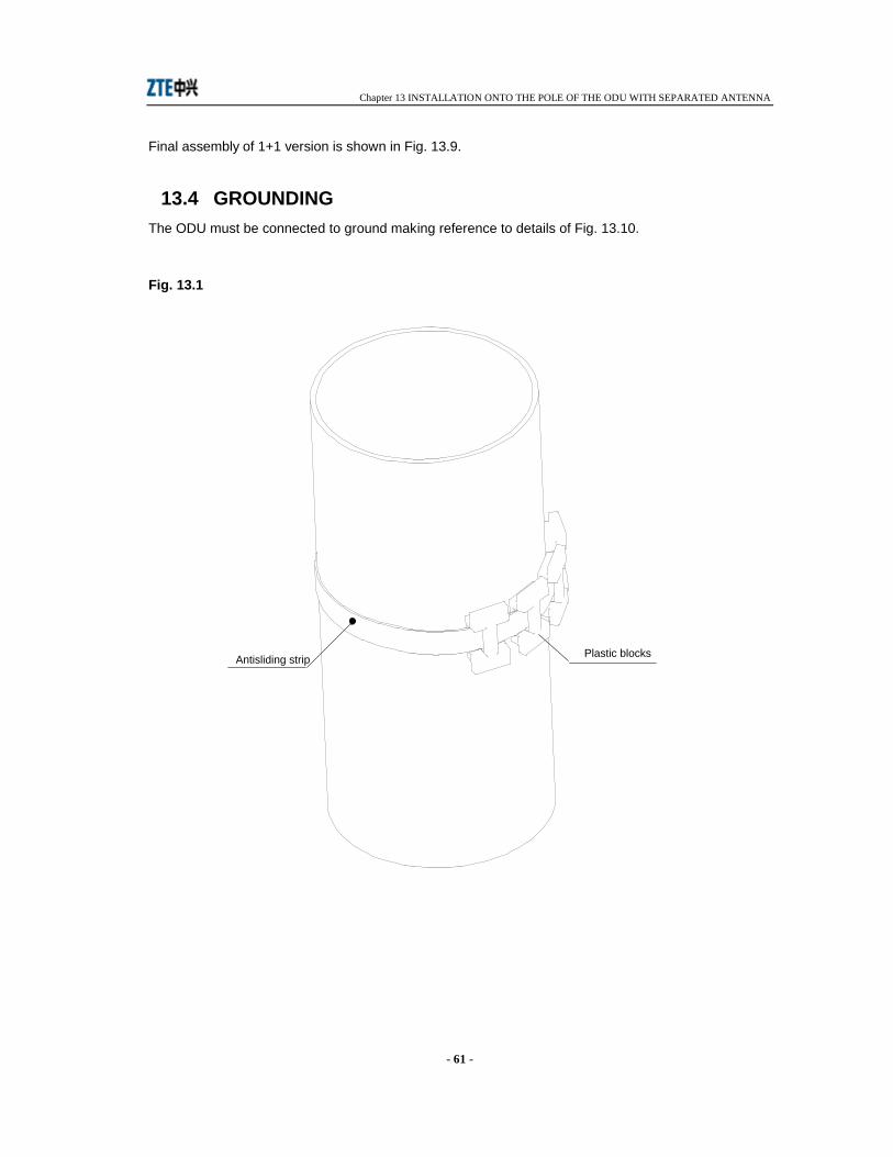
13.1 INSTALLATION KIT Following installation kits are supplied with the equipment depending on different versions:
• 1+0 version - antisliding strip (see Fig. 13.1) - supporting plate plus 60-114 mm pole fixing bracket and relevant nuts and bolts (see Fig.
13.2) - adapting tools and relevant bolts and nuts for 219 mm pole (see Fig. 13.3) - antenna side flange, variable as function of RF frequency (see Fig. 13.4) - support with ODU fast locking mechanism (see Fig. 13.2) - flexible waveguide trunk for connection to antenna (optional) (see Fig. 13.2) - kit for ground connection making part of ODU
• 1+1 version - antisliding strip (see Fig. 13.1) - supporting plate plus pole fixing bracket and relevant nuts and bolts (see Fig. 13.2) - adapting tools and relevant bolts and nuts for 219 mm pole (see Fig. 13.3) - hybrid with ODU fast locking mechanism (see Fig. 13.5) - flexible waveguide trunk for connection to antenna (optional (see Fig. 13.2) - kit for ground connection making part of the two ODUs.

Chapter 13 INSTALLATION ONTO THE POLE OF THE ODU WITH SEPARATED ANTENNA
- 59 -
13.2 REQUIRED TOOLS FOR MOUNTING (NOT SUPPLIED) • N.2 13mm torque wrench • N.1 15 mm torque wrench • N.1 17 mm torque wrench • N.1 3 mm allen wrench
13.3 INSTALLATION PROCEDURE Installation procedure proceeds according to the following steps:
• Version 1+0: installation onto the pole of the supporting plate 2 • Version 1+1: installation onto the pole of the supporting plate 1
• Installation of the ODU (common to both 1+0 and 1+1 version) • ODU grounding
1+0 version - Installation onto the pole of the supporting plate
Fig. 13.1 - Mount antislide strip around the pole. The position of the plastic blocks depends on the position of the supporting plate (see next step) Fig. 13.2 - Adhere the supporting plate to the antisliding strip plastic blocks and then secure it to the pole through the fixing bracket for 60-114 mm pole (see Fig. 13.2). Bolts and nuts are available on the supporting plate. Tightening torque must be 32 Nm. Warning: As shown in Fig. 13.3 an adapting kit must be used for the 219 mm pole. It consists of an additional plate to enlarge the standard supporting plate dimension and relevant U-bolt for 219 mm pole fixing. Fig. 13.4 - Fix the flexible waveguide to the antenna side flange. Four fixing screws are available the dimensions of which depend on the waveguide type. Tighten progressively and alternatively the four screws with the following torque:
Tab. 13.1
Frequencies Screw Tool Torque from 18 to 38 GHz allen screw M3 allen key 2.5 mm 1 Nm
up to 15 GHz allen screw M4 allen key 3 mm 2 Nm
2. In case of 219 mm pole, an adapting kit is supplied for the purpose.
Chapter 13 INSTALLATION ONTO THE POLE OF THE ODU WITH SEPARATED ANTENNA
- 60 -
Fig. 13.4 - Fix the antenna side flange to the support with ODU fast locking mechanism. The flange can be mounted horizontally (as shown in Fig. 13.4) or vertically as function of convenience. Fig. 13.5 - Fix the support with ODU fast locking mechanism to the supporting plate making use of available bolts and nuts. Fig. 13.5 shows three possible positions. Tightening torque must be 18 Nm.
1+1 version - Installation onto the pole of the supporting plate
Fig. 13.1 - Mount antislide strip around the pole. The position of the plastic blocks depends on the position of the supporting plate (see next step) Fig. 13.2 - Position the supporting plate to the antisliding strip plastic blocks and then secure it to the pole through the fixing bracket for 60-114 mm pole (see Fig. 13.2). Bolts and nuts are available on the supporting plate kit. Tightening torque must be 32 Nm. Fig. 13.6 - Secure the hybrid with ODU fast locking mechanism to the supporting plate using bolt and nuts available on the support plate. Tightening torque must be 18 Nm. Remove the plastic cover from the hybrid flange sides. Warning: Do not remove the foil from the hybrid flange sides. Fig. 13.6 - Fix the flexible waveguide to the antenna side flange. Four fixing screws are available the dimensions of which depend on the waveguide type. Tighten progressively and alternatively the four screws with the following torque:
Tab. 13.2
Frequencies Screw Tool Torque from 18 to 38 GHz allen screw M3 allen key 2.5 mm 1 Nm
up to 15 GHz allen screw M4 allen key 3 mm 2 Nm
Warning: It is advisable to shape the waveguide flexible trunk, connecting ODU flange with antenna flange as shown in Fig. 13.9. This avoids possible condensate to be channelled towards the ODU flange.
Installation of the ODU
1. Remove the plastic cover from the ODU flange side. Apply silicon grease e.g. type RHODOSIL PATE 4 to the O-ring of Fig. 13.8. Warning: Do not remove the foil from the flange.
2. Bring the ODU with the two hands and position the ODU handle at the bottom side. 3. Position the ODU body close to the support with ODU fast locking mechanism and align ODU
side flange (see Fig. 13.8) to antenna side flange ( see Fig. 13.4 - 1+0 version) or hybrid side flange (see Fig. 13.6 - 1+1 version).
Note: For 1+0 version the ODU can assume positions of Fig. 13.7 depending on the polarisation. 4. With respect to the flange alignment, turn the ODU body approx. 30° anti-clockwise and then
insert the ODU body into the support and search for alignment between reference tooth on the support (see Fig. 13.4 - 1+0 version or Fig. 13.6 - 1+1 version) and ODU body reference tooth (see detail Fig. 13.8)
5. When alignment is achieved, turn the ODU body clockwise until “clack” is heard and the ODU rotation stops.
6. Secure ODU body on the support by tightening bolts (1) (see Fig. 13.4 - 1+0 version or Fig. 13.6 - 1+1 version). Tightening torque must be 6 Nm.
Chapter 13 INSTALLATION ONTO THE POLE OF THE ODU WITH SEPARATED ANTENNA
- 61 -
Final assembly of 1+1 version is shown in Fig. 13.9.
13.4 GROUNDING The ODU must be connected to ground making reference to details of Fig. 13.10. Fig. 13.1
Antisliding strip Plastic blocks
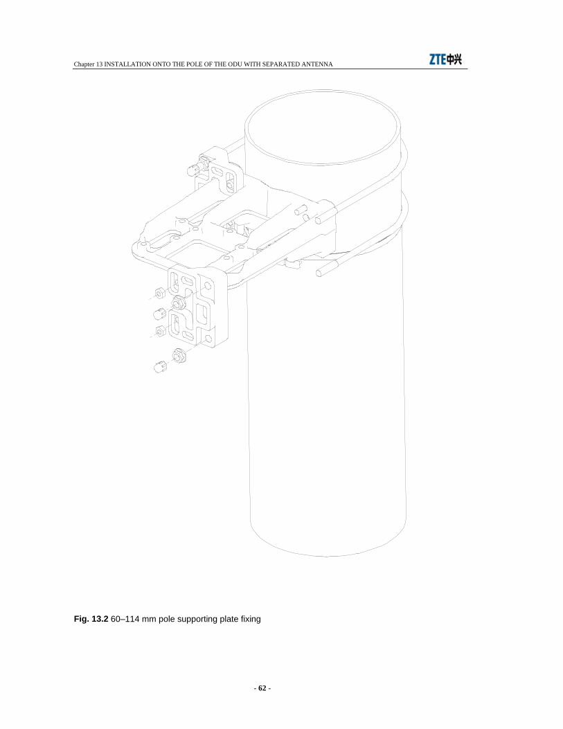
Chapter 13 INSTALLATION ONTO THE POLE OF THE ODU WITH SEPARATED ANTENNA
- 62 -
Fig. 13.2 60–114 mm pole supporting plate fixing
Adapting kit for 219 mm pole
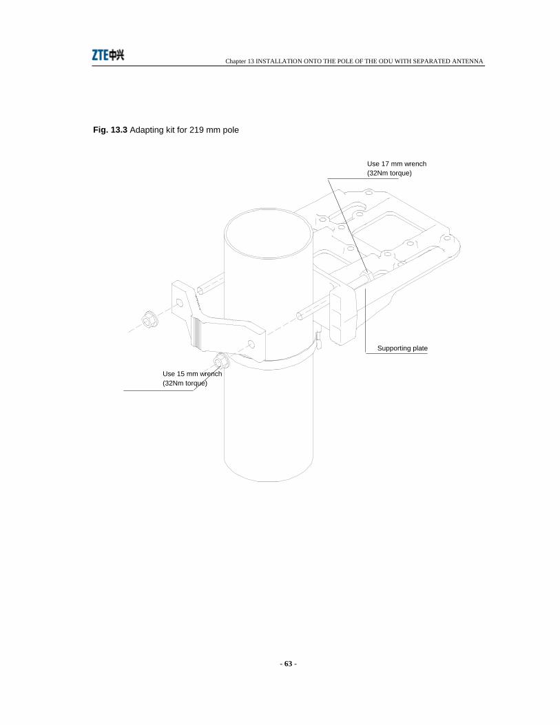
Chapter 13 INSTALLATION ONTO THE POLE OF THE ODU WITH SEPARATED ANTENNA
- 63 -
Fig. 13.3 Adapting kit for 219 mm pole
60-114 mm pole supporting plate fixing
Supporting plate
Use 15 mm wrench (32Nm torque)
Use 17 mm wrench (32Nm torque)

Chapter 13 INSTALLATION ONTO THE POLE OF THE ODU WITH SEPARATED ANTENNA
- 64 -
Mounting possible position
Flexible waveguide trunk
Antenna side flange
Support with ODU fast locking mechanism
Reference tooth
Position of antenna side flange
Reference tooth
1
1
13 mm wrench 6 Nm torque
Fig. 13.4 Mounting possible position
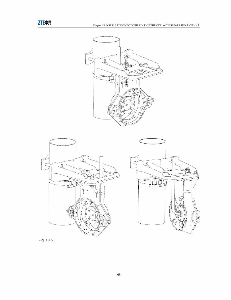
Chapter 13 INSTALLATION ONTO THE POLE OF THE ODU WITH SEPARATED ANTENNA
- 65 -
Fig. 13.5
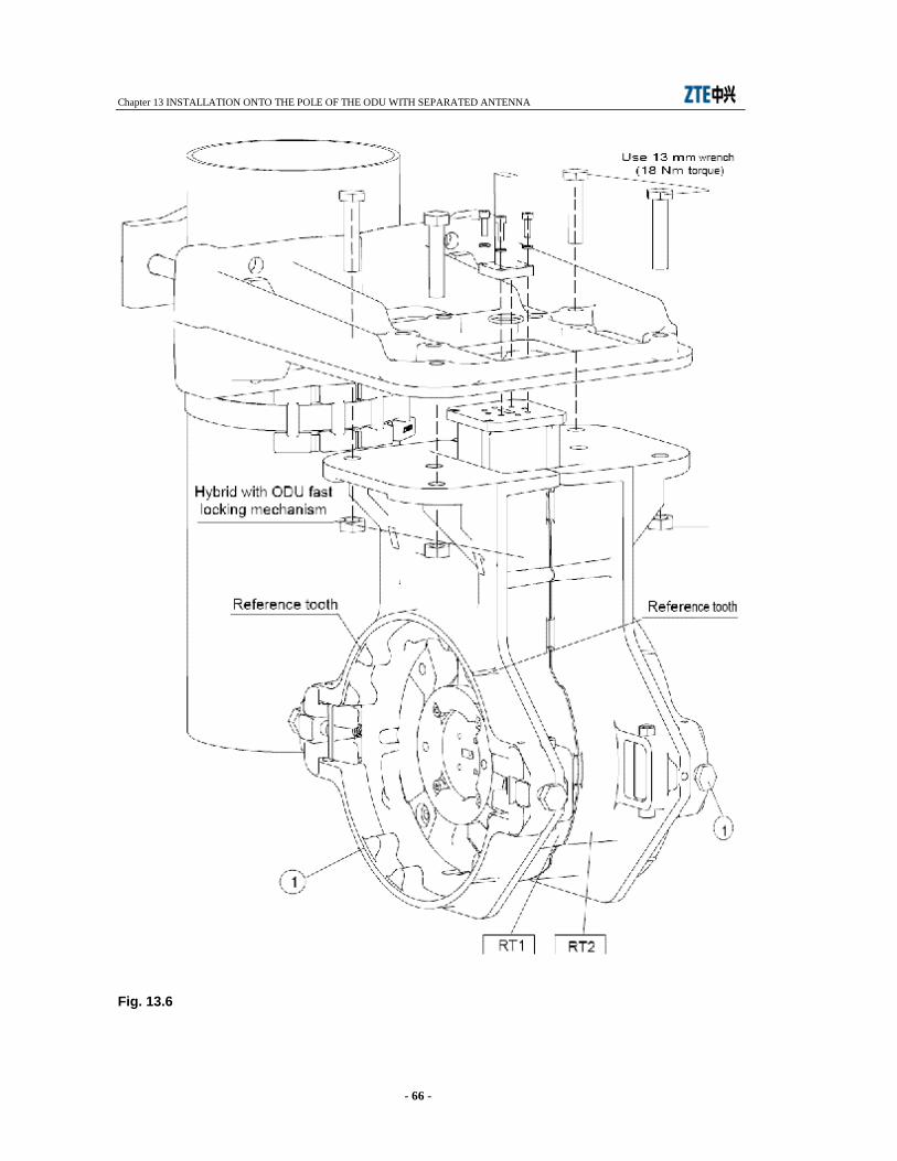
Chapter 13 INSTALLATION ONTO THE POLE OF THE ODU WITH SEPARATED ANTENNA
- 66 -
Fig. 13.6
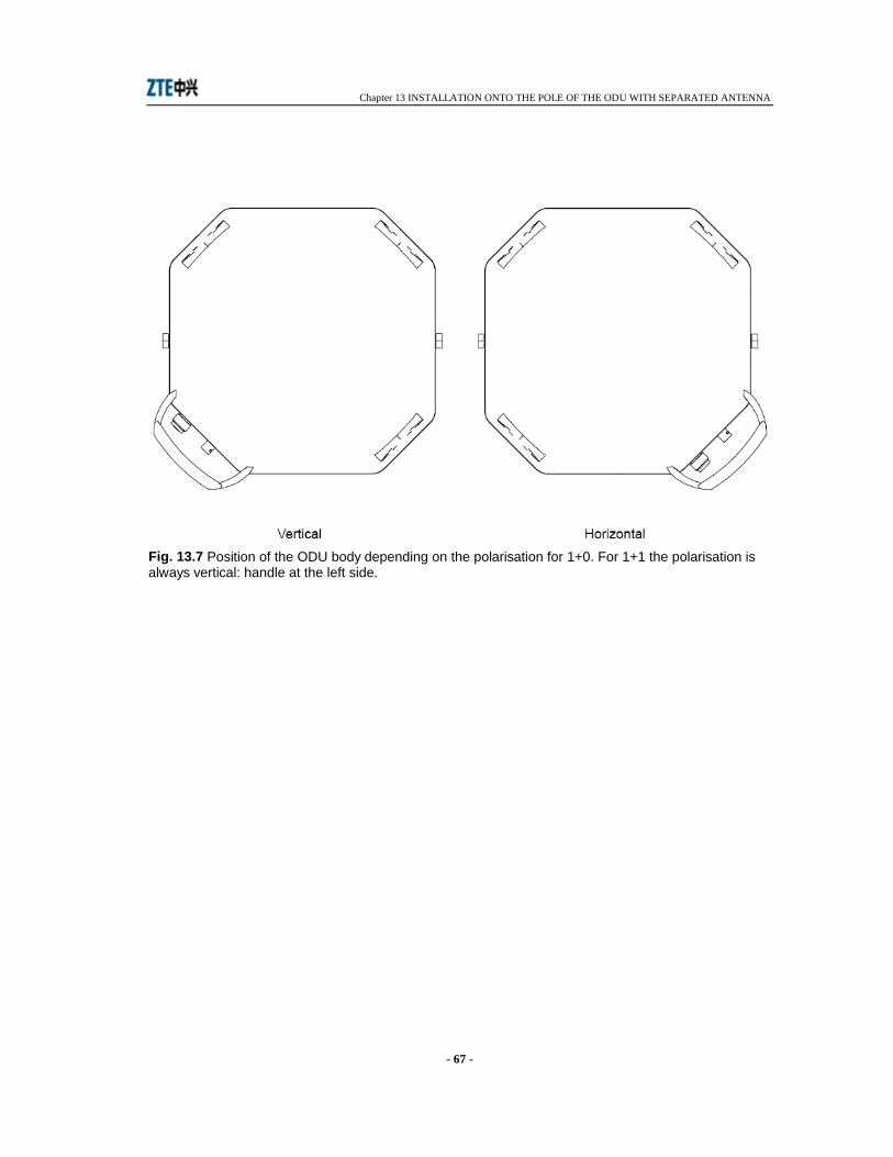
Chapter 13 INSTALLATION ONTO THE POLE OF THE ODU WITH SEPARATED ANTENNA
- 67 -
Fig. 13.7 Position of the ODU body depending on the polarisation for 1+0. For 1+1 the polarisation is always vertical: handle at the left side.
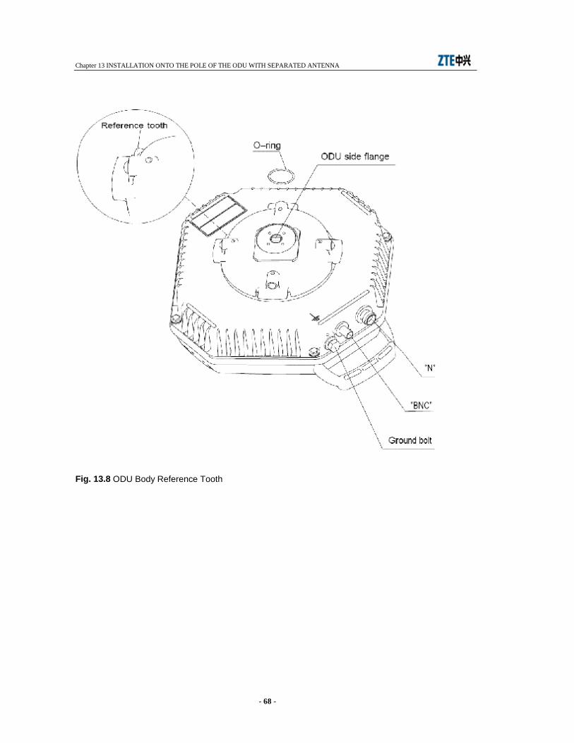
Chapter 13 INSTALLATION ONTO THE POLE OF THE ODU WITH SEPARATED ANTENNA
- 68 -
Fig. 13.8 ODU Body Reference Tooth
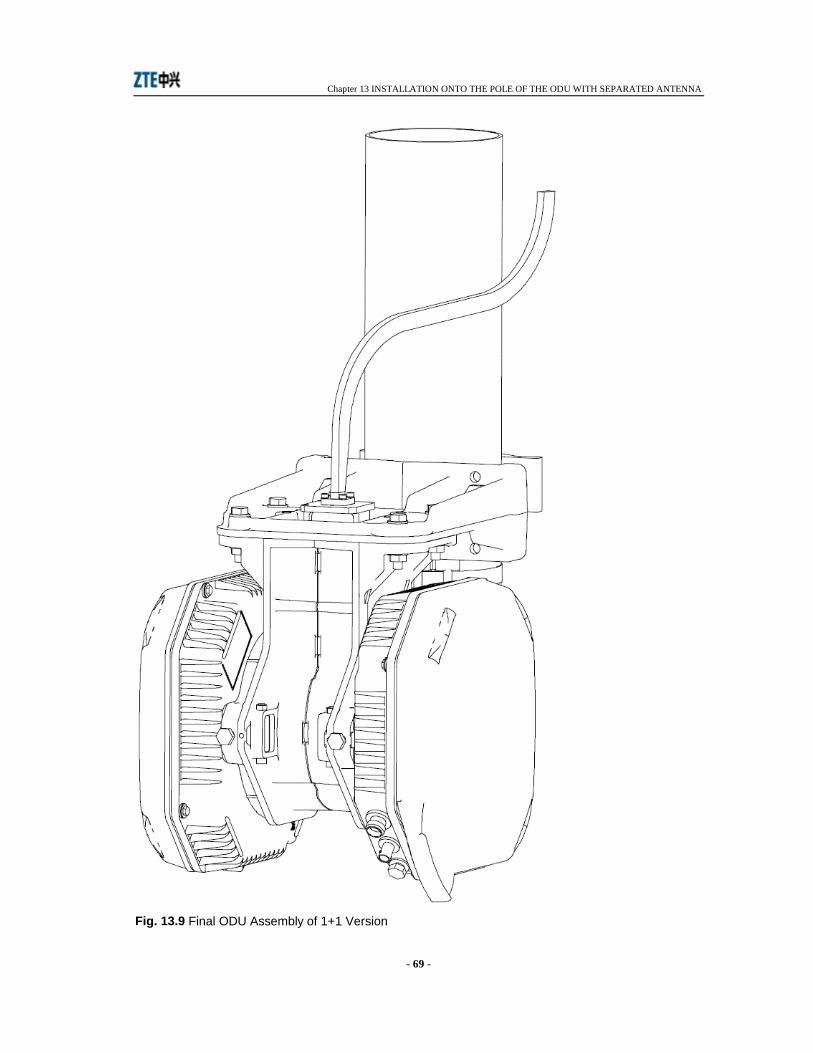
Chapter 13 INSTALLATION ONTO THE POLE OF THE ODU WITH SEPARATED ANTENNA
- 69 -
Fig. 13.9 Final ODU Assembly of 1+1 Version
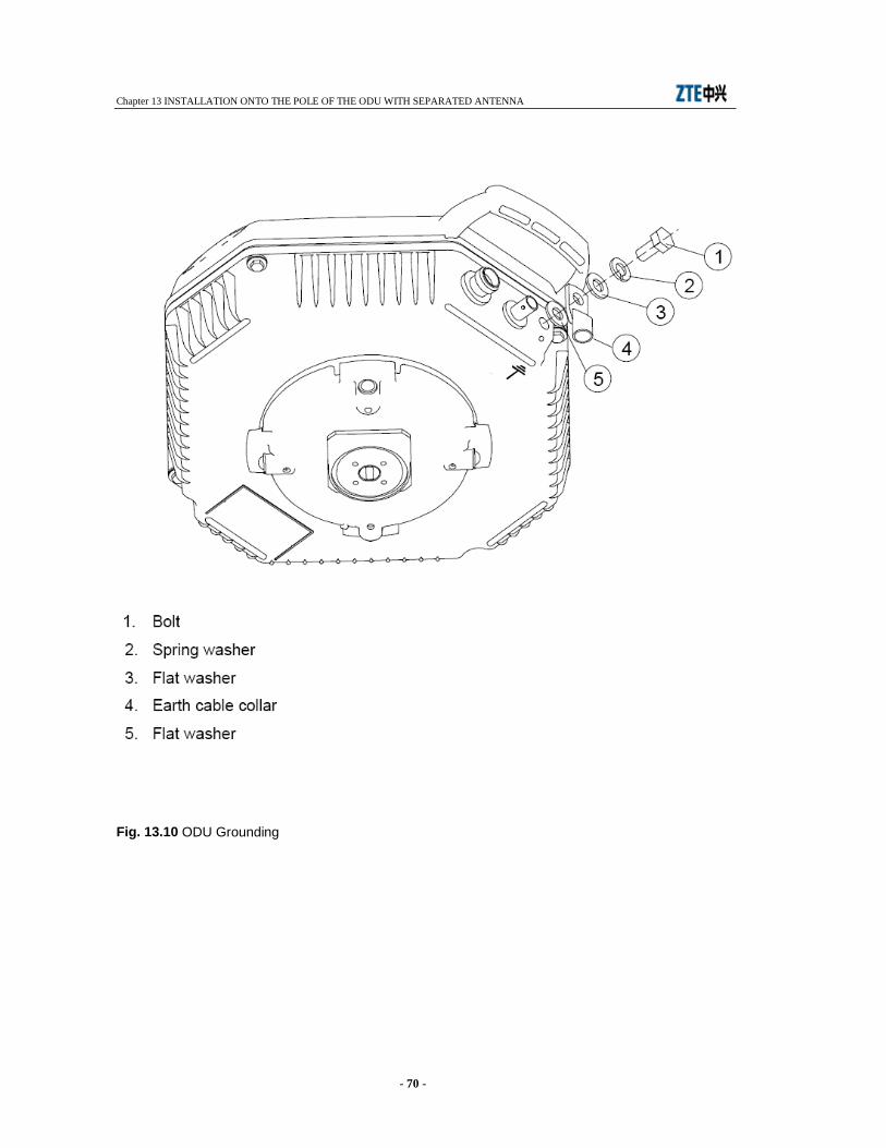
Chapter 13 INSTALLATION ONTO THE POLE OF THE ODU WITH SEPARATED ANTENNA
- 70 -
Fig. 13.10 ODU Grounding

Chapter 14 INSTALLATION ONTO THE WALL OF THE ODU WITH SEPARATED ANTENNA
- 71 -
14 INSTALLATION ONTO THE WALL OF THE ODU WITH SEPARATED ANTENNA
14.1 INSTALLATION KIT Following installation kits are supplied with the equipment depending on different versions:
• 1+0 version - wall supporting plate with additional contact surface extension plates (see Fig. 14.1) - antenna side flange, variable as function of RF frequency (see Fig. 14.2) - support with ODU fast locking mechanism (see Fig. 14.2) - flexible waveguide trunk for connection to antenna (optional) (see Fig. 14.2) - kit for ground connection making part of ODU
• 1+1 version - supporting plate with additional contact surface extension tools (see Fig. 14.1) - hybrid with ODU fast locking mechanism (see Fig. 14.4) - flexible waveguide trunk for connection to antenna (optional (see Fig. 14.2) - kit for ground connection making part of the two ODUs.
14.2 REQUIRED TOOLS FOR MOUNTING (NOT SUPPLIED) • N.2 13mm torque wrench • N.1 15 mm torque wrench • N.1 17 mm torque wrench • N.1 3 mm allen wrench
14.3 INSTALLATION PROCEDURE Installation procedure proceeds according to the following steps:
• Version 1+0: installation onto the wall of the supporting plate
• Version 1+1: installation onto the wall of the supporting plate • Installation of the ODU (common to both 1+0 and 1+1 version) • ODU grounding
Chapter 14 INSTALLATION ONTO THE WALL OF THE ODU WITH SEPARATED ANTENNA
- 72 -
1+0 version - Installation onto the wall of the supporting plate
Fig. 14.1 - Fix on the supporting plate the two supplied extension plates to increase the wall contact surface. Fig. 14.1 - Secure the supporting plate on the wall using the more suitable screws. Fig. 14.2 - Fix the flexible waveguide to the antenna side flange. Four fixing screws are available the dimensions of which depend on the waveguide type. Tighten progressively and alternatively the four screws with the following torque:
Tab. 14.1
Frequencies Screw Tool Torque from 18 to 38 GHz allen screw M3 allen key 2.5 mm 1 Nm
up to 15 GHz allen screw M4 allen key 3 mm 2 Nm Fig. 14.2 - Fix the antenna side flange to the support with ODU fast locking mechanism. The flange can be mounted horizontally (as shown in Fig. 14.2) or vertically as function of convenience. Fig. 14.3 - Fix the support with ODU fast locking mechanism to the supporting plate making use of available bolts and nuts. Fig. 14.3 shows three possible positions. Tightening torque must be 18 Nm.
1+1 version - Installation onto the wall of the supporting plate
Fig. 14.1 - Fix on the supporting plate the two supplied extension plates to increase the wall contact surface. Fig. 14.1 - Secure the supporting plate on the wall using the more suitable screws. Fig. 14.4 - Secure the hybrid with ODU fast locking mechanism to the supporting plate using bolt and nuts available on the support plate. Tightening torque must be 18 Nm. Remove the plastic cover from the hybrid flange sides. Warning: Do not remove the foil from the hybrid flange sides. Fig. 14.4 - Fix the flexible waveguide to the antenna side flange. Four fixing screws are available the dimensions of which depend on the waveguide type. Tighten progressively and alternatively the four screws with the following torque:
Tab. 14.2
Frequencies Screw Tool Torque from 18 to 38 GHz allen screw M3 allen key 2.5 mm 1 Nm
up to 15 GHz allen screw M4 allen key 3 mm 2 Nm
Warning: It is advisable to shape the waveguide flexible trunk, connecting ODU flange with antenna flange as shown in Fig. 14.7 This avoids possible condensate to be channelled towards the ODU flange.
Installation of the ODU
Chapter 14 INSTALLATION ONTO THE WALL OF THE ODU WITH SEPARATED ANTENNA
- 73 -
1. Remove the plastic cover from the ODU flange side. Apply silicon grease e.g. type RHODOSIL PATE 4 to the O-ring of Fig. 14.6. Warning: Do not remove the foil from the flange.
2. Bring the ODU with the two hands and position the ODU handle at the bottom side. 3. Position the ODU body close to the support with ODU fast locking mechanism and align ODU
side flange (see Fig. 14.6) to antenna side flange ( see Fig. 14.2 - 1+0 version) or hybrid side flange (see Fig. 14.4 - 1+1 version).
Note: For 1+0 version the ODU can assume positions of Fig. 14.5 depending on the polarisation. 4. With respect to the flange alignment, turn the ODU body approx. 30° anti-clockwise and then
insert the ODU body into the support and search for alignment between reference tooth on the support (see Fig. 14.2 - 1+0 version or Fig. 14.4 - 1+1 version) and ODU body reference tooth (see detail Fig. 14.6)
5. When alignment is achieved, turn the ODU body clockwise until “clack” is heard and the ODU rotation stops.
6. Secure ODU body on the support by tightening bolts (1) (see Fig. 14.2 - 1+0 version or Fig. 14.4 - 1+1 version). Tightening torque must be 6 Nm.
Final assembly of 1+1 version is shown in Fig. 14.7.

Chapter 14 INSTALLATION ONTO THE WALL OF THE ODU WITH SEPARATED ANTENNA
- 74 -
14.4 GROUNDING The ODU must be connected to ground making reference to details of Fig. 14.8.
Fig. 14.1 Wall supporting plate
Wall supporting plate
Extension plate
Supporting plate
M8 bolt and nut
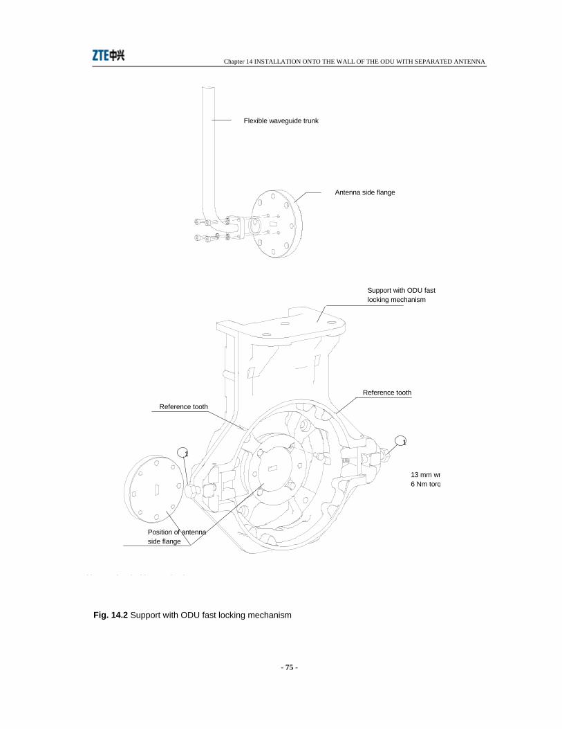
Chapter 14 INSTALLATION ONTO THE WALL OF THE ODU WITH SEPARATED ANTENNA
- 75 -
Fig. 14.2 Support with ODU fast locking mechanism
Support with ODU fast locking mechanism
Flexible waveguide trunk
Antenna side flange
Support with ODU fast locking mechanism
Reference tooth
Position of antenna side flange
Reference tooth
1
1
13 mm wrench 6 Nm torque

Chapter 14 INSTALLATION ONTO THE WALL OF THE ODU WITH SEPARATED ANTENNA
- 76 -
Fig. 14.3 Mounting possible positions
Mounting possible positions
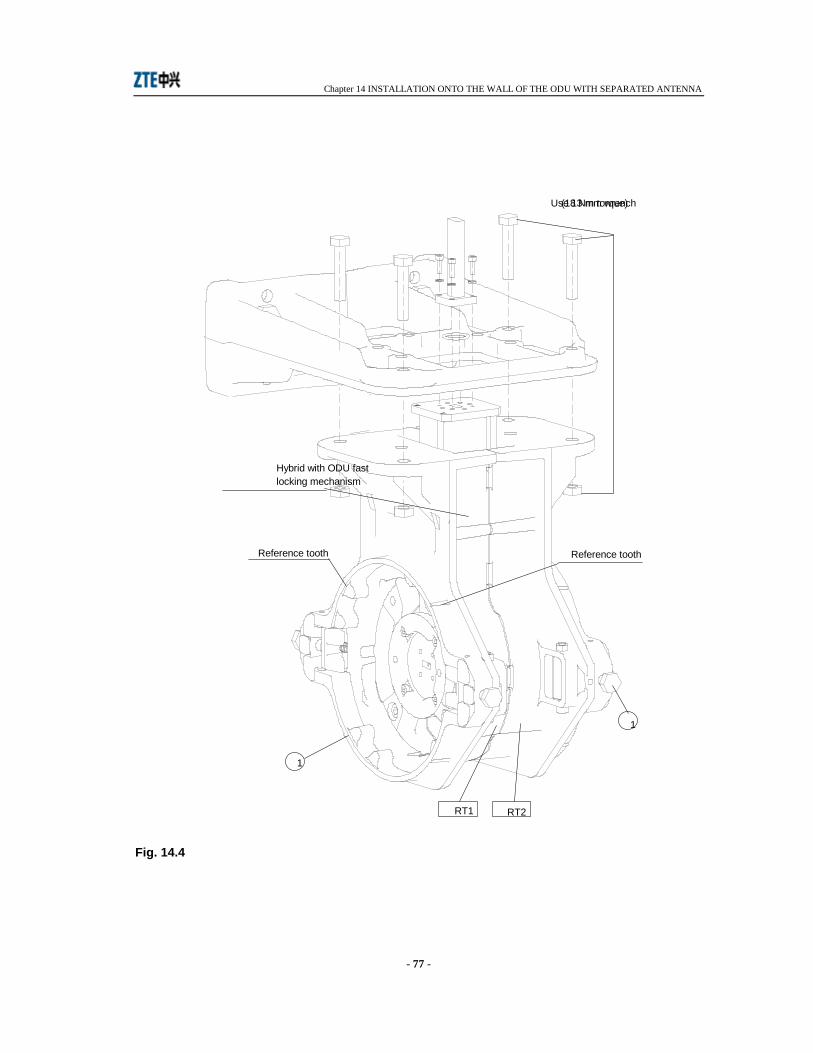
Chapter 14 INSTALLATION ONTO THE WALL OF THE ODU WITH SEPARATED ANTENNA
- 77 -
Fig. 14.4
Use 13 mm wrench (18 Nm torque)
Reference toothReference tooth
Hybrid with ODU fast locking mechanism
1
1
RT1 RT2
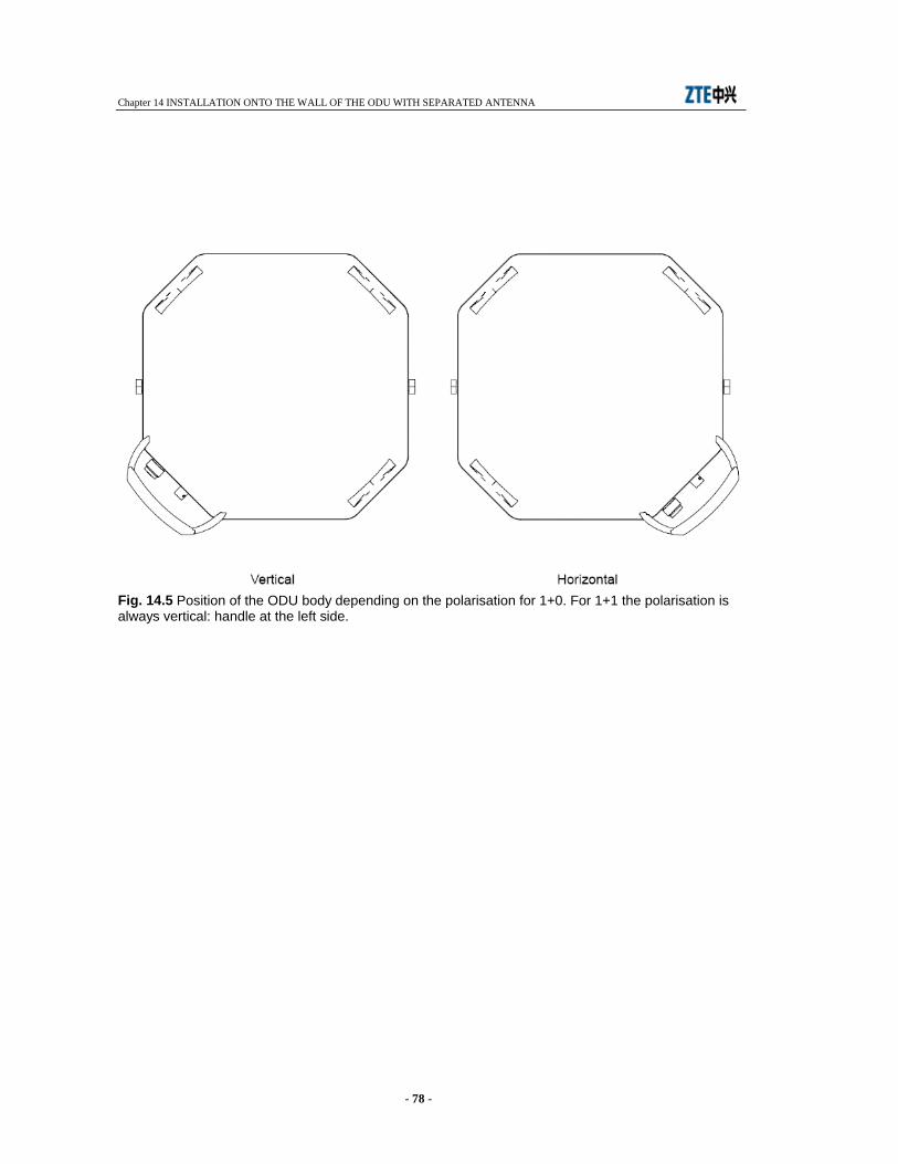
Chapter 14 INSTALLATION ONTO THE WALL OF THE ODU WITH SEPARATED ANTENNA
- 78 -
Fig. 14.5 Position of the ODU body depending on the polarisation for 1+0. For 1+1 the polarisation is always vertical: handle at the left side.
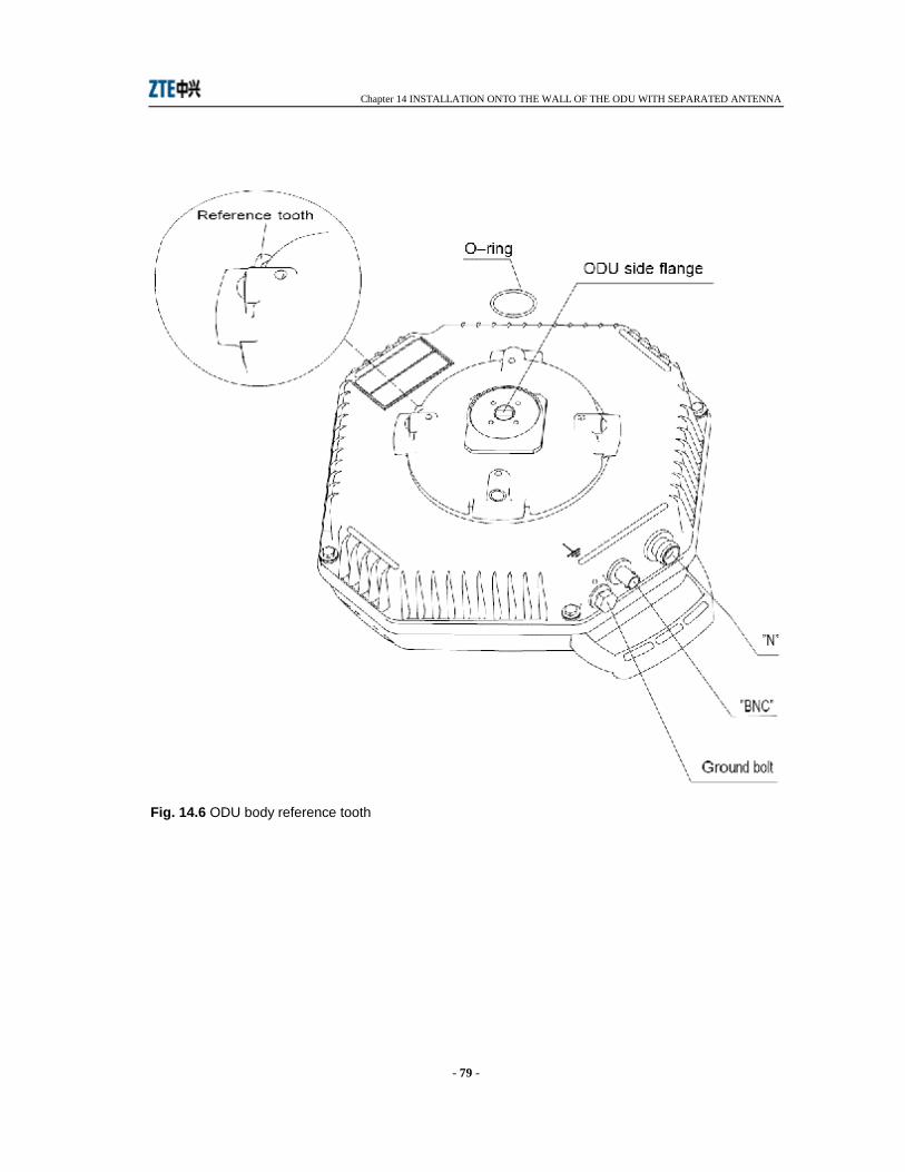
Chapter 14 INSTALLATION ONTO THE WALL OF THE ODU WITH SEPARATED ANTENNA
- 79 -
Fig. 14.6 ODU body reference tooth
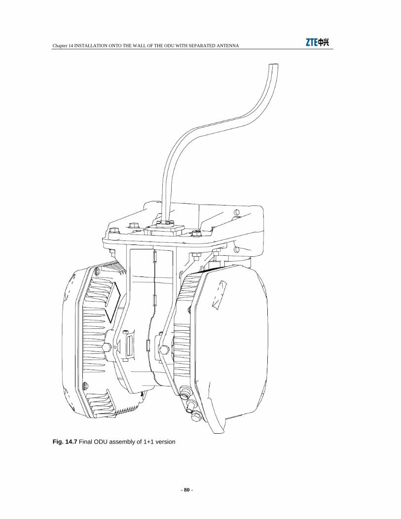
Chapter 14 INSTALLATION ONTO THE WALL OF THE ODU WITH SEPARATED ANTENNA
- 80 -
Fig. 14.7 Final ODU assembly of 1+1 version
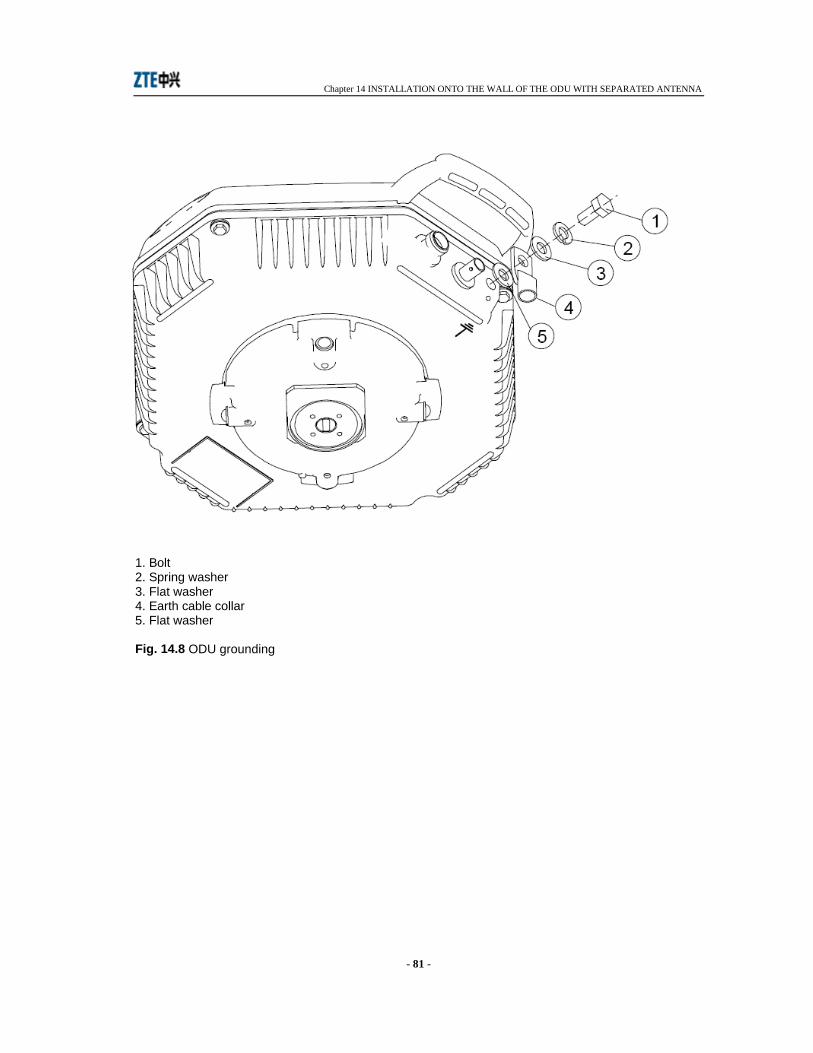
Chapter 14 INSTALLATION ONTO THE WALL OF THE ODU WITH SEPARATED ANTENNA
- 81 -
1. Bolt 2. Spring washer 3. Flat washer 4. Earth cable collar 5. Flat washer Fig. 14.8 ODU grounding

Chapter 15 INSTALLATION ONTO THE POLE OF THE ODU WITH INTEGRATED ANTENNA
- 82 -
15 INSTALLATION ONTO THE POLE OF THE ODU WITH INTEGRATED ANTENNA
15.1 FOREWORD The installation onto the pole of the ODU with integrated antenna concerns both 1+0 and 1+1 versions.
15.2 INSTALLATION KIT Following installation kits are supplied with the equipment depending on different versions:
1+0 version
• 60 to 114 mm pole mounting kit consisting of: - centering ring and relevant screws (see Fig. 15.1) - antislide strip (see Fig. 15.2) - pole support system and pole fixing brackets (see Fig. 15.3) - ODU with O-ring and devices for ground connection
1+1 version
• pole mounting kit from 60 to 114 mm for 1+1 consisting of: - centering ring and relevant screws (see Fig. 15.1) - antislide strip (see Fig. 15.2) - pole support system and pole fixing brackets (see Fig. 15.3)
• hybrid mechanical body (see Fig. 15.12) • polarization twist disk (see Fig. 15.13) • 2 ODUs with O-rings and devices for ground connection
15.3 REQUIRED TOOLS FOR MOUNTING (NOT SUPPLIED) • N.2 13 mm torque wrench • N.1 15 mm torque wrench • N.1 17 mm torque wrench • N.1 3 mm allen wrench
Chapter 15 INSTALLATION ONTO THE POLE OF THE ODU WITH INTEGRATED ANTENNA
- 83 -
15.4 INSTALLATION PROCEDURE Installation procedure proceeds according with the following steps:
1+0 version
1. installation onto the pole of the support system 2. installation of the antenna 3. installation of ODU 4. antenna aiming 5. ODU grounding
1+1 version
1. installation onto the pole of the support system 2. installation of the antenna 3. installation of hybrid circuit 4. installation of the two ODUs 5. antenna aiming 6. ODU grounding
15.4.1 Installation onto the pole of the support system and the antenna Fig. 15.1 - Set the antenna in such a position as to be able to operate on its rear side. Locate the five threaded holes around antenna flange. Mount centering ring onto antenna flange and tight it with 3 calibrated bolts.
Caution: centering ring should be mounted so that the screws do not stick out. Define if the antenna will be mounted with vertical or horizontal polarization. Check that free drain holes stay at bottom side. Mount bolt type M10x30, in position A leaving it loose of 2 cm approx. With horizontal polarization mount bolt type M10x30 in position D, leaving it loose of 2 cm approx. Fig. 15.2 - Mount antislide strip onto the pole. Place blocks as in Fig. 15.2 following antenna aiming direction. Tighten the strip with screwdriver. Fig. 15.3 - Mount pole supporting system with relevant pole fixing brackets following antenna aiming direction as indicated by arrow. Antislide strip should result at the center of supporting plate. Supporting system should lean against antislide clamp with the tooth as in Fig. 15.4. Position the antenna in such a way that bolt in position A or D of Fig. 15.1 cross through hole E of Fig. 15.5. Secure the support system to the pole by means of the pole fixing brackets and relevant fixing bolts. Fig. 15.6 - Rotate the antenna body until the remainder three antenna holes coincide with the three support holes. Secure the antenna to the support by thightening the relevant passing through bolts.
Chapter 15 INSTALLATION ONTO THE POLE OF THE ODU WITH INTEGRATED ANTENNA
- 84 -
15.4.2 Installation of ODU
1+0 version
1. Apply silicon grease e.g. RHODOSIL PATE 4” to the O-ring (4) of Fig. 15.9 by protecting finger hands with gloves.
2. Bring the ODU with the two hands and position the ODU handle at the bottom side. The ODU handle can assume position of Fig. 15.7 depending on the polarization.
3. Position the ODU body near the support system and align ODU side flange to antenna side flange (see Fig. 15.8). With respect to the flange alignment, turn the ODU body approx. 30° anti-clockwise and then insert the ODU body into the support and search for alignemnt between reference tooth on the support (see Fig. 15.8) and ODU body reference tooth (see detail of Fig. 15.9).
4. When alignment is achieved, turn the ODU body clockwise until “clack” is heard and the ODU rotation stops. Fig. 15.10 and Fig. 15.11 show ODU housing final position for vertical and horizontal polarization respectively.
5. Secure ODU body on the support system by tightening bolts (1) of Fig. 15.8.
1+1 version
Fig. 15.12 - Apply silicon grease, type “RHODOSIL PATE 4” to O-rings (1). Insert O-rings (1) and (6) into twist polarization disk (2). Vertical polarization Fix the disk on hybrid flange placing marker (4), on disk, close to V mark. Horizontal polarization Fix the disk on hybrid flange placing reference (4), on disk, close to H mark. Caution: Twist disk has two planes. Take care of position marker (4) on twist disk. The position of marker (4) plane should be in contact to hybrid like in figure. Tighten progressively and alternatively four screws (7) with four spring washers (8) with the following torque:
Tab. 15.1
Frequencies Screw Tool Torque from 18 to 38 GHz allen screw M3 allen key 2.5 mm 1 Nm
up to 15 GHz allen screw M4 allen key 3 mm 2 Nm
Fig. 15.13 - Fix hybrid to support system with four bolts (1) taking care of RT1/RT2 position shown by labels of Fig. 15.13. Tighten progressively and alternatively four bolts (1).

Chapter 15 INSTALLATION ONTO THE POLE OF THE ODU WITH INTEGRATED ANTENNA
- 85 -
15.4.3 ODU installation The installation procedure of the two ODUs is the same.
1. Apply silicon grease e.g. RHODOSIL PATE 4” to the O-ring (4) of the Fig. 15.9 by protecting finger hands with gloves.
2. Bring the ODU with the two hands and position the ODU handle at the bottom side. For 1+0 the ODU can assune position of Fig. 15.7 depending on the polarisation. For 1+1 the handle ODU position is always placed at the right side (horizontal polarization).
3. Position the ODU body near the support system and align ODU side flange to antenna side flange (see Fig. 15.8). With respect to the flange alignment, turn the ODU body approx. 30° anti-clockwise and then insert the ODU body into the support and search for alignemnt between reference tooth on the support (see Fig. 15.8) and ODU body reference tooth (see detail of Fig. 15.9).
4. When alignment is achieved, turn the ODU body clockwise until “clack” is heard and the ODU rotation stops. Fig. 15.10 and Fig. 15.11 show ODU housing final position for vertical and horizontal polarization respectively for 1+0 version. Fig. 15.14 shows ODU housing final position for 1+1 version.
5. Secure ODU body on the support system by tightening bolts (1) of Fig. 15.8.
15.5 ANTENNA AIMING Antenna aiming for 1+0 version and 1+1 version is the same. The antenna aiming devices allow to perform the following adjustments with respect to the starting aiming position:
• Horizontal ± 15° operating on the nut (3) shown in Fig. 15.15, only after having loosen the nuts (7), (8), (9), (10) of Fig. 15.16.
• Vertical ± 15° operating on vertical adjustment worm screw (2) shown in Fig. 15.15 only after having loosen nuts (1), (2), (11) of Fig. 15.16 and (4) of Fig. 15.15.
For adjustment from 0° to +30° extract nut (1) Fig. 15.16 and position it in
hole (4), extract nut (2) Fig. 15.16 and position it in hole (6). Operate on vertical adjustment worm screw (2) after having loosen nuts (1), (2), (11) of Fig. 15.16 and (4) of Fig. 15.15.
For adjustment from 0° to -30° extract nut (1) of Fig. 15.16 and position it
in hole (3), extract nut (2) of Fig. 15.16 and position it in hole (5). Operate on vertical adjustment worm screw (2) after having loosen nuts (1), (2), (11) of Fig. 15.16 and (4) of Fig. 15.15.
For vertical adjustment some markers, every 10°, are available on support. The bigger marker gives 0° starting aiming position. Once the optimum aiming position is obtained, tighten firmly the four nuts (1), (2), (11) of Fig. 15.16 and (4) of Fig. 15.15 for vertical adjustment and the four nuts (7), (8), (9), (10) of Fig. 15.16 for horizontal adjustment. Tighten with 15 mm wrench and 32 Nm torque.
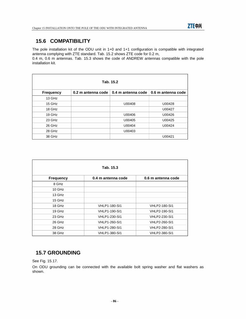
Chapter 15 INSTALLATION ONTO THE POLE OF THE ODU WITH INTEGRATED ANTENNA
- 86 -
15.6 COMPATIBILITY The pole installation kit of the ODU unit in 1+0 and 1+1 configuration is compatible with integrated antenna complying with ZTE standard. Tab. 15.2 shows ZTE code for 0.2 m, 0.4 m, 0.6 m antennas. Tab. 15.3 shows the code of ANDREW antennas compatible with the pole installation kit.
Tab. 15.2
Frequency 0.2 m antenna code 0.4 m antenna code 0.6 m antenna code 13 GHz 15 GHz U00408 U00428 18 GHz U00427 19 GHz U00406 U00426 23 GHz U00405 U00425 26 GHz U00404 U00424 28 GHz U00403 38 GHz U00421
Tab. 15.3
Frequency 0.4 m antenna code 0.6 m antenna code 8 GHz
10 GHz 13 GHz 15 GHz 18 GHz VHLP1-180-SI1 VHLP2-180-SI1 19 GHz VHLP1-190-SI1 VHLP2-190-SI1 23 GHz VHLP1-230-SI1 VHLP2-230-SI1 26 GHz VHLP1-260-SI1 VHLP2-260-SI1 28 GHz VHLP1-280-SI1 VHLP2-280-SI1 38 GHz VHLP1-380-SI1 VHLP2-380-SI1
15.7 GROUNDING See Fig. 15.17. On ODU grounding can be connected with the available bolt spring washer and flat washers as shown.
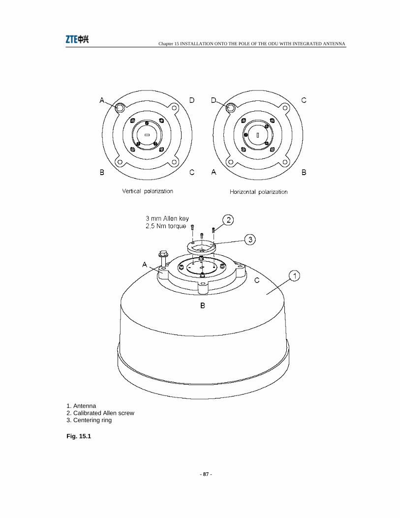
Chapter 15 INSTALLATION ONTO THE POLE OF THE ODU WITH INTEGRATED ANTENNA
- 87 -
1. Antenna 2. Calibrated Allen screw 3. Centering ring Fig. 15.1

Chapter 15 INSTALLATION ONTO THE POLE OF THE ODU WITH INTEGRATED ANTENNA
- 88 -
1. Steel belt 2. Plastic blocks Fig. 15.2 Antislide strip

Chapter 15 INSTALLATION ONTO THE POLE OF THE ODU WITH INTEGRATED ANTENNA
- 89 -
Fig. 15.3 Support mount on pole
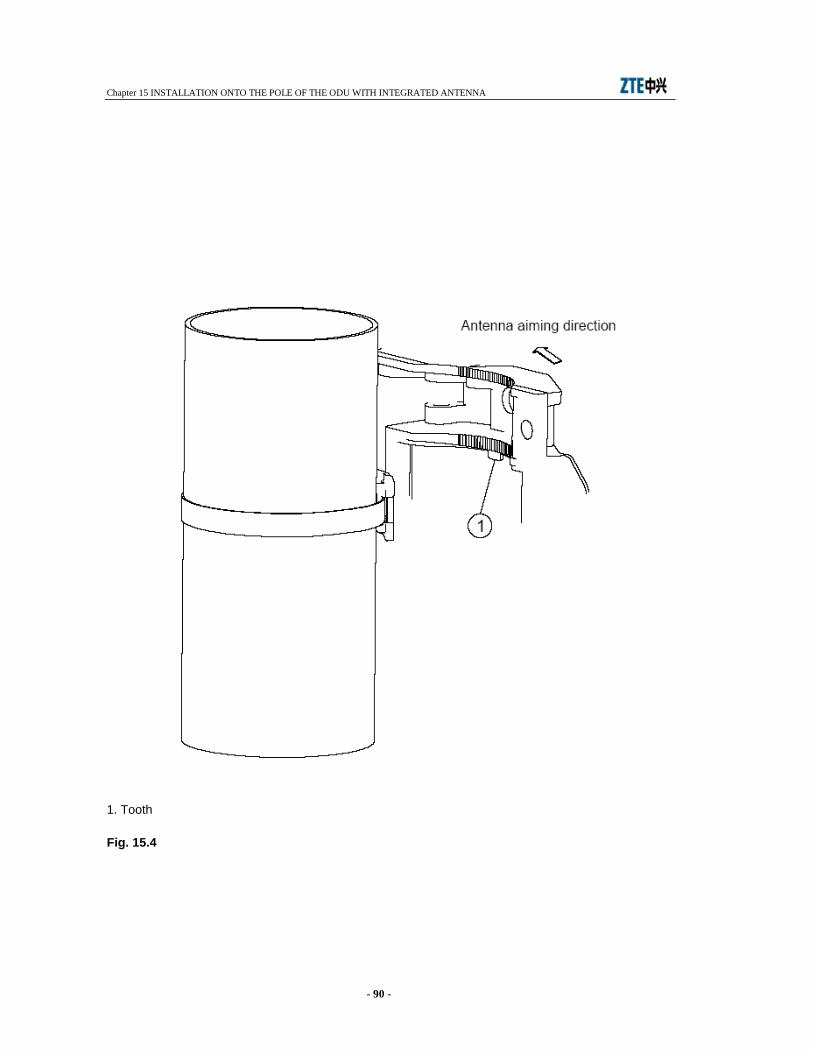
Chapter 15 INSTALLATION ONTO THE POLE OF THE ODU WITH INTEGRATED ANTENNA
- 90 -
1. Tooth Fig. 15.4
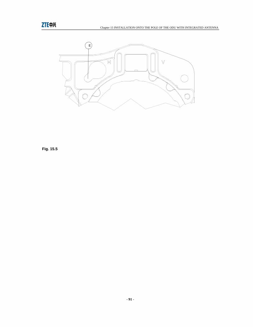
Chapter 15 INSTALLATION ONTO THE POLE OF THE ODU WITH INTEGRATED ANTENNA
- 91 -
Fig. 15.5
E
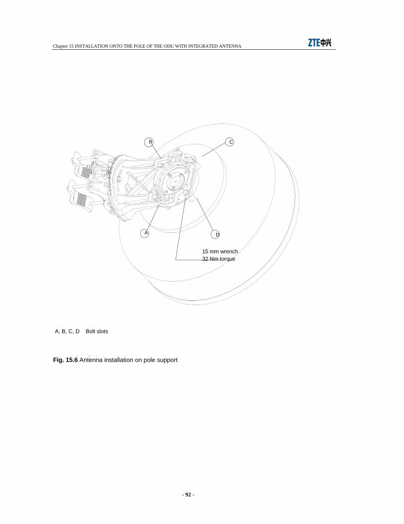
Chapter 15 INSTALLATION ONTO THE POLE OF THE ODU WITH INTEGRATED ANTENNA
- 92 -
Antenna installation on pole support
DA
B C
15 mm wrench32 Nm torque
A, B, C, D Bolt slots
Fig. 15.6 Antenna installation on pole support
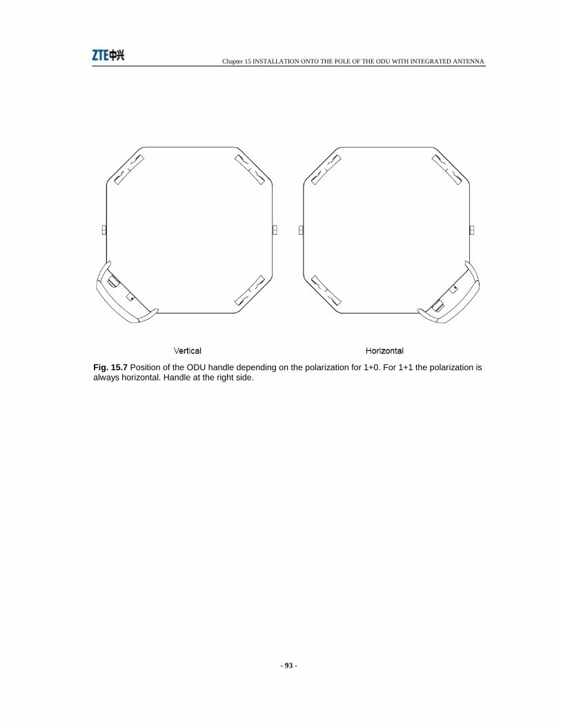
Chapter 15 INSTALLATION ONTO THE POLE OF THE ODU WITH INTEGRATED ANTENNA
- 93 -
Fig. 15.7 Position of the ODU handle depending on the polarization for 1+0. For 1+1 the polarization is always horizontal. Handle at the right side.
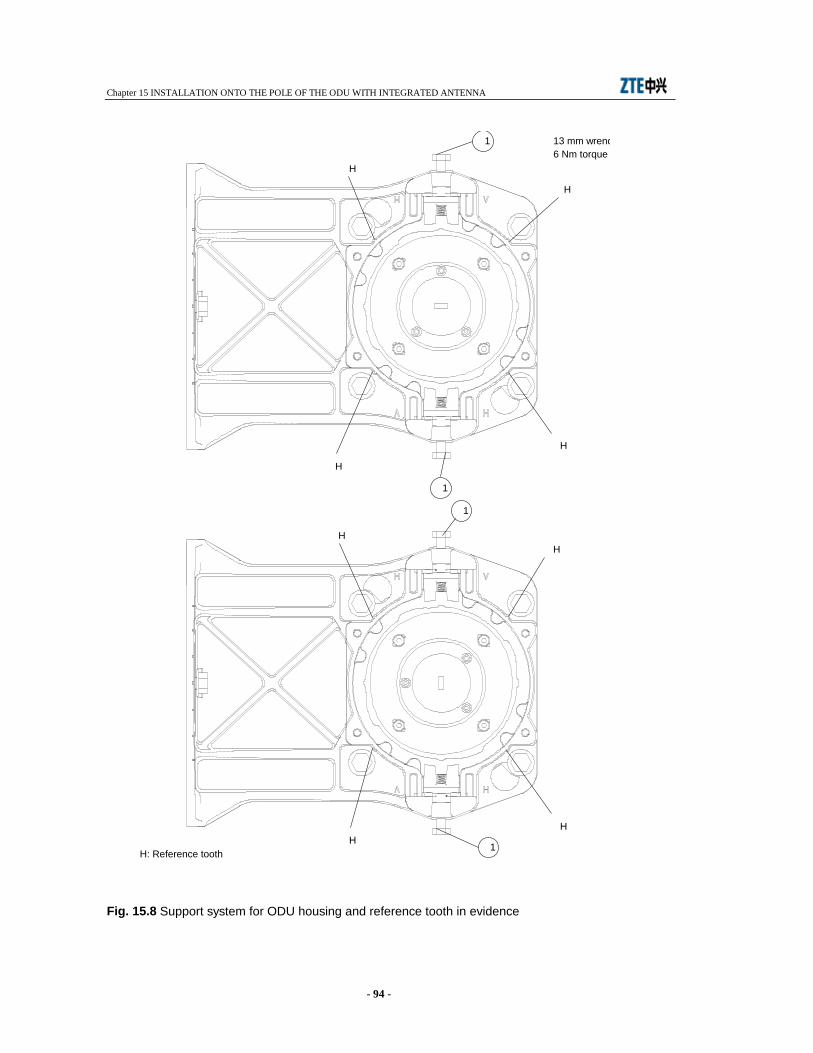
Chapter 15 INSTALLATION ONTO THE POLE OF THE ODU WITH INTEGRATED ANTENNA
- 94 -
Fig. 15.8 Support system for ODU housing and reference tooth in evidence Support system for ODU housing and reference tooth in evidence
1
1
1
H
H
H
H
HH
HH
H: Reference tooth
13 mm wrench 6 Nm torque
1
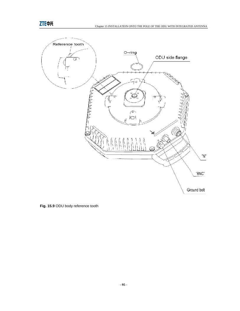
Chapter 15 INSTALLATION ONTO THE POLE OF THE ODU WITH INTEGRATED ANTENNA
- 95 -
Fig. 15.9 ODU body reference tooth
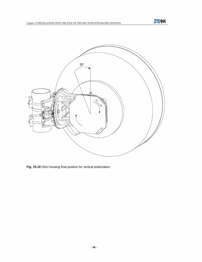
Chapter 15 INSTALLATION ONTO THE POLE OF THE ODU WITH INTEGRATED ANTENNA
- 96 -
Fig. 15.10 ODU housing final position for vertical polarization
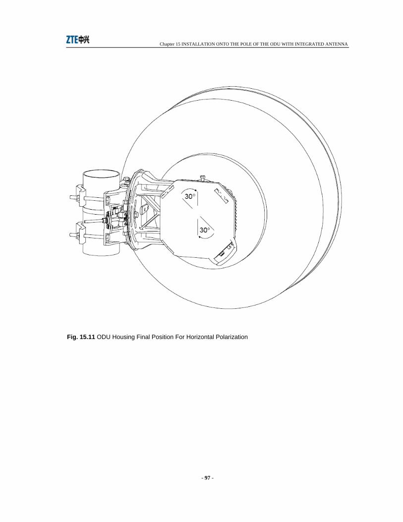
Chapter 15 INSTALLATION ONTO THE POLE OF THE ODU WITH INTEGRATED ANTENNA
- 97 -
Fig. 15.11 ODU Housing Final Position For Horizontal Polarization

Chapter 15 INSTALLATION ONTO THE POLE OF THE ODU WITH INTEGRATED ANTENNA
- 98 -
Fig. 15.12 Hybrid and twist disk

Chapter 15 INSTALLATION ONTO THE POLE OF THE ODU WITH INTEGRATED ANTENNA
- 99 -
1. Bolts 2. Spring washer Fig. 15.13 Hybrid Mount On Pole Support
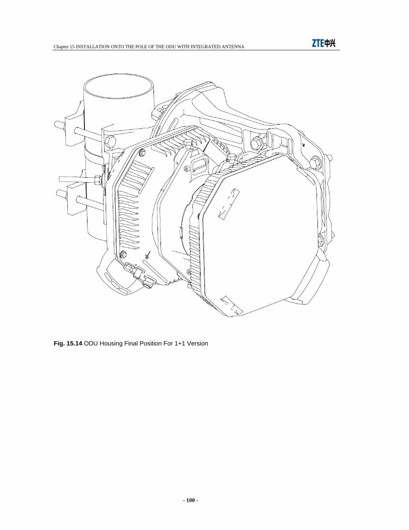
Chapter 15 INSTALLATION ONTO THE POLE OF THE ODU WITH INTEGRATED ANTENNA
- 100 -
Fig. 15.14 ODU Housing Final Position For 1+1 Version
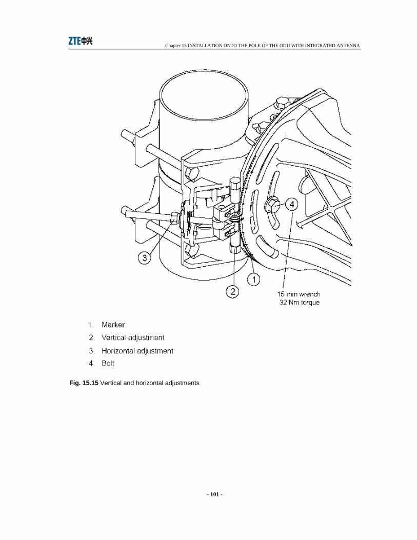
Chapter 15 INSTALLATION ONTO THE POLE OF THE ODU WITH INTEGRATED ANTENNA
- 101 -
Fig. 15.15 Vertical and horizontal adjustments
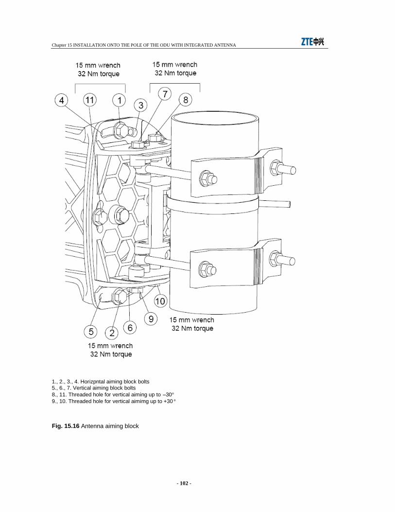
Chapter 15 INSTALLATION ONTO THE POLE OF THE ODU WITH INTEGRATED ANTENNA
- 102 -
1., 2., 3., 4. Horizpntal aiming block bolts 5., 6., 7. Vertical aiming block bolts 8., 11. Threaded hole for vertical aiming up to –30° 9., 10. Threaded hole for vertical aimimg up to +30 ° Fig. 15.16 Antenna aiming block
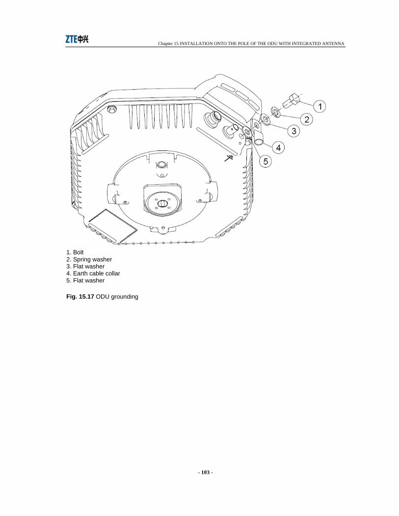
Chapter 15 INSTALLATION ONTO THE POLE OF THE ODU WITH INTEGRATED ANTENNA
- 103 -
1. Bolt 2. Spring washer 3. Flat washer 4. Earth cable collar 5. Flat washer Fig. 15.17 ODU grounding
Chapter 16 LINE-UP OF THE RADIO HOP
- 104 -
16 LINE-UP OF THE RADIO HOP
16.1 LINE-UP OF THE RADIO HOP The line-up consists of the following steps:
• on site radio terminal installation (perform user connections and ODU installation as described in the relevant chapters)
• equipment switch-on (operate the ON/OFF switch on the IDU front) • antenna alignment for maximum received RF signal level • network element configuration • check measurements.
16.1.1 Antenna alignment and received field measurement Purpose of antenna alignment is to maximize the RF received signal level. Proceed as follows:
• connect a multimeter to BNC connector on the ODU for AGC measurement • adjust antenna pointing as soon as the maximum AGC voltage value is achieved.
The relationship between AGC voltage and received field is shown by Fig. 16.1. The received field level has a tolerance of ±4 dB in the full temperature range.
16.1.2 Network element configuration A factory default address is assigned to each network element that must normally be reconfigured on site following the network administrator rules. To this purpose it is required to connect the PC, where the IE has been installed, to the network interfaces. This has to be done via Ethernet cable. Warning: the checks that follow require a good knowledge of the program use. The description of each menu and relevant windows are given by the program itself as help on line.
Perform the login to the equipment by entering: • Equipment IP address in address bar of IE • User ID (default: SYSTEM) • Password: (default: MICR)
16.1.3 Radio Checks It is advisable to perform the following measurements to check the correct operation of the radio hop:
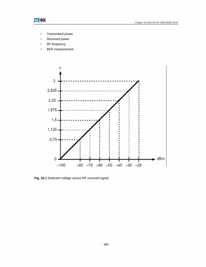
Chapter 16 LINE-UP OF THE RADIO HOP
- 105 -
• Transmitted power • Received power • RF frequency • BER measurement
Fig. 16.1 Detected voltage versus RF received signal
Chapter 17 PERIODICAL CHECKS
- 106 -
17 PERIODICAL CHECKS
17.1 GENERAL Periodical checks are used to check correct operation of the radio equipment without the presence of any alarm condition. The Web_CIT running on the PC are used for the purpose.
17.2 CHECKS TO BE CARRIED OUT The following checks must be carried out:
• check of the trasmitted power; • check of the received field strength (the reading must match the value resulting from hop
calculations); • check of bit error rate and hop performances.
For checking procedures, please refer to Web-CIT and relevant help-on line.
Chapter 18 COMPOSITION OF THE INDOOR UNIT
- 107 -
18 COMPOSITION OF THE INDOOR UNIT
18.1 GENERAL The IDU is offered in main versions:
• 1+0 • 1+1

Chapter 19 COMPOSITION OF OUTDOOR UNIT
- 108 -
19 COMPOSITION OF OUTDOOR UNIT
19.1 GENERAL The ODU consists of a mechanical structure that houses all the transceiver circuitry. In 1+1 version the connection to the antenna is performed through a passive hybrid. Both transceiver and hybrid are offered in different versions depending on the operating bands, the antenna configuration etc... A label attached on the ODU structure shows the most significant parameters as go/return frequency value, subband, operating band and part number. For example the P/N GA0001/001, shown by the label, identifies the following:
• 18 GHz operating band
• 1010 MHz go/return frequency value
• 1L operating subband low
• serial number
• month and year
18 GHz
G/R
SB
S/N
DATA CODE
