tutorial 4: combined axial and bending problem … 4: combined axial and bending problem in this...
TRANSCRIPT

TUTORIAL 4: Combined Axial and Bending Problem
In this tutorial you will learn how to draw a bar that has bends along its length and therefore will have both axial and bending stresses acting on cross-sections along the bar length. This type of bar falls into an eccentric loading problem in the area of combined loads. The bar has a 2”x2” square cross-section and is made out of ‘Lafayette Steel’. The bar will be modeled in ANSYS by defining its square cross section in a Sketch and then drawing a Path to Sweep the cross-section along. This sweeping action will create the 3D bar element that includes the bends along its length. The complete bar model is shown in the figure shown below. The lengths of the bar segments are 8 inches, 16 inches and 8 inches in the x-direction. The vertical jog in the bar is 4 inches in the y-direction. An axial load of 10,000 lb. is applied to the bar in the x-direction. This axial load will create both axial and bending normal stresses in the middle, 16” length of the bar and the deformations obtained will also reflect the combined effect of the axial force and bending moment in the portion of the bar.
Initial Project Space Setup Set up a new Static Structural project in a new ANSYS environment. Change the material by Importing in ‘Lafayette Steel’ and set it as the Default Material for the material, set the Units to US Customary and start up the Sketching environment with the Units in Inches and with the Auto Constraints turned On.
Sketching of Rectangular Cross-Section Sketch out a rectangle on the YZ Plane. Make sure the Units are in Inches. Add two dimensions to set the width and height of the rectangle to be 2 inches each and also add the two dimensions that help center the square cross-section on the YZ axes.
x
y
8”
16”
8”
4”
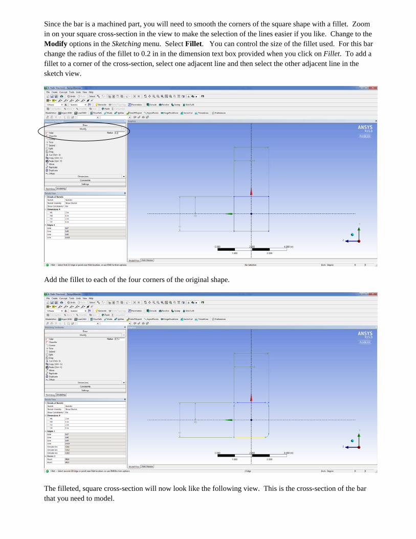
Since the bar is a machined part, you will need to smooth the corners of the square shape with a fillet. Zoom in on your square cross-section in the view to make the selection of the lines easier if you like. Change to the Modify options in the Sketching menu. Select Fillet. You can control the size of the fillet used. For this bar change the radius of the fillet to 0.2 in in the dimension text box provided when you click on Fillet. To add a fillet to a corner of the cross-section, select one adjacent line and then select the other adjacent line in the sketch view.
Add the fillet to each of the four corners of the original shape.
The filleted, square cross-section will now look like the following view. This is the cross-section of the bar that you need to model.
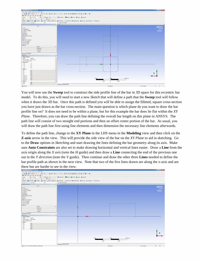
You will now use the Sweep tool to construct the side profile line of the bar in 3D space for this eccentric bar model. To do this, you will need to start a new Sketch that will define a path that the Sweep tool will follow when it draws the 3D bar. Once this path is defined you will be able to assign the filleted, square cross-section you have just drawn as the bar cross-section. The main question is which plane do you want to draw the bar profile line on? It does not need to be within a plane, but for this example the bar does lie flat within the XY Plane. Therefore, you can draw the path line defining the overall bar length on this plane in ANSYS. The path line will consist of two straight end portions and then an offset center portion of the bar. As usual, you will draw the path line first using line elements and then dimension the necessary line elements afterwards.
To define the path line, change to the XY Plane in the LHS menu in the Modeling view and then click on the Z-axis arrow in the view. This will provide the side view of the bar on the XY Plane to aid in sketching. Go to the Draw options in Sketching and start drawing the lines defining the bar geometry along its axis. Make sure Auto Constraints are also set to make drawing horizontal and vertical lines easier. Draw a Line from the axis origin along the X axis (note the H guide) and then draw a Line connecting the end of the previous one out in the Y direction (note the V guide). Then continue and draw the other three Lines needed to define the bar profile path as shown in the next view. Note that two of the five lines drawn are along the x-axis and are there but are harder to see in the view.

Using the Dimension menu options in Sketching, dimension the lengths of the two end lines at 8 inches, the length of the middle line at 16 inches, and the jog at 4 inches. You only need these four dimensions overall. You should get something that looks like the view below. Use the F7 key if your model goes out of view.
Now change to the Modeling tab and click on an ISO view. Expand the LHS menu leafs for the XY Plane and the YZ Plane. You should have now have a Sketch2 in the XY Plane and a Sketch1 in the YZ Plane defined or something very similar.
To create a 3D bar having the profile defined with the filleted, square cross-section along its length using these two Sketches you will use the Sweep tool from the top menu. This tool is shown in the above view. Click on Sweep and look at what information you need to provide for this operation.

To Sweep you will need to provide both the Profile – which is the filleted, square cross-section in Sketch1 on the YZ Plane and the Path – which is the line segments in Sketch 2 on the XY Plane. You just need to tell ANSYS which is which. To set the Profile, click on Sketch 1 leaf in the Tree and then click Apply. Then click on the Path box, click on the Sketch 2 leaf in the Tree and then click Apply. Try this out to fill in these two boxes in the bottom LHS menu for the Details View.
Once the Profile and Path are defined click Generate and see what happens.

The Geometry of the 3D bar is now complete in the model. Continue modeling by opening the Mechanical Model window by double-clicking on Model in the main ANSYS window.
Generate a Coarse Mesh for the bar and then add two Forces, one located at each end on the bar, that apply a tensile force of 10,000 lb. to each end.
To help restrain the bar from rotating about the X-axis or moving out of the XY plane, a few boundary conditions will be specified for the bar. One of the bar ends could be also designated as a fixed support, but this changes up the deformation view and also introduces artificial stress concentrations at the fixed end of the bar. Add a Displacement Constraint to a location on an edge of the near end face of the bar that restrains any z-axis displacement of that point (Z Component = 0). Use the Edge Selection tool from the top toolbar to help select the edge. In the view shown below the one edge selected is the front side edge of the near end cross-
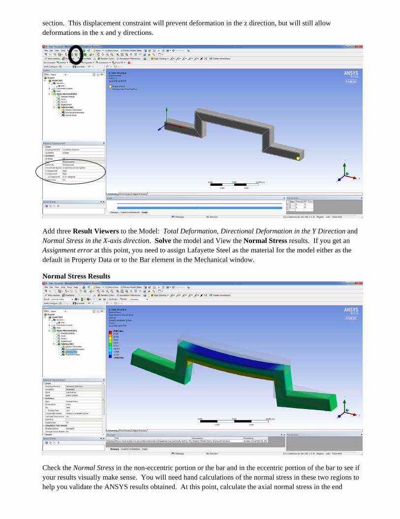
section. This displacement constraint will prevent deformation in the z direction, but will still allow deformations in the x and y directions.
Add three Result Viewers to the Model: Total Deformation, Directional Deformation in the Y Direction and Normal Stress in the X-axis direction. Solve the model and View the Normal Stress results. If you get an Assignment error at this point, you need to assign Lafayette Steel as the material for the model either as the default in Property Data or to the Bar element in the Mechanical window.
Normal Stress Results
Check the Normal Stress in the non-eccentric portion or the bar and in the eccentric portion of the bar to see if your results visually make sense. You will need hand calculations of the normal stress in these two regions to help you validate the ANSYS results obtained. At this point, calculate the axial normal stress in the end

portions of the bar due to the axial load carried and then calculate the normal stress in the middle portion of the bar due to the combined axial force and bending moment.
To help you compare your hand calculations with the ANSYS results in these two locations on the bar you can set up section cut planes of the bar element at specific locations along the bar length.
Change to a XY Plane view by clicking on the Z-axis in the view. Also change to an undeformed view by changing the Result to 0.0 (Undeformed). Then select the toolbar option in the top toolbar to create a New Section Plane
After clicking on this tool, draw a line vertically in the view through the non-eccentric portion of the bar.
After drawing this you will see a section cut taken of the bar.

If you take an ISO view you will see the normal (x-axis) stress distribution across the cross-section at this cut location. Compare the normal stress on the section cut plane with the one you calculated by hand for this bar. The normal stress in this portion of the bar for a cross-section with 4 in2 area would be 2500 psi. You can approximate the new area of the filleted cross-section using your ANSYS normal stress result.
Go back to the XY Plane view and create another section plane at the mid-section of the eccentric bar by drawing a vertical line through the cross-section at this point. To view the whole bar again, click off the checkmark in the Section Planes view in the very bottom LHS menu. If the box is checked you will see a section cut view and if it is not you will see the whole bar.
Change to the ISO view and see the normal (x-axis) stress distribution across the cross-section.

The normal stress varies from a maximum compressive stress at the top surface to a maximum tensile stress on the bottom extreme fiber. Also the tensile stress is greater than the compressive stress due to the combined axial stress and bending stress at this location in the bar. To go back and forth between the section planes use the check boxes in the bottom left corner. Zoom in on the end view of the stress distribution on the section cut in the view. Using the probe tool, click on the maximum compressive stress at the top surface and the maximum tensile stress at the bottom surface. Compare these values to your hand calculation values. The values ANSYS provides may be different due to the moment of inertia you use in your calculation since it is for a 2”x2” cross-section with no filleted corners. However they should be within 3 or 4% typically.
Save your file and work and fill out the Online Survey using the link provided for Tutorial 4.