design tall masonry walls - seaoa convention/2017... · 2017-05-14 · design for axial forces and...
TRANSCRIPT

J.B
. S
PE
ED
SC
HO
OL
OF
EN
GIN
EE
RIN
G
1
Design Tall Masonry Walls
SEAoA 51th Anniversary
Convention and ConferenceTempe, AZ
June 1, 2017
W. Mark McGinley, Ph. D., PE FASTM

Outline
Over view of Single wythe walls
Present ASD Reinforced Masonry Wall Design Provisions
Present SD Code provisions Masonry Wall Design Provisions
Present Tall Wall Design Examples
2

Exterior Load Bearing and Non Loadbearing single
Wythe Masonry Walls
Single Wythe Walls
3

Exterior Reinforced Masonry RM Typically subjected to
Axial and Flexure Loads
If Load bearing
there is a vertical
load May be
eccentrically
Applied
Roof/floor
Diaphragm
Supports Wall
CODE - COMBINED LOADING – GIVES ASSUMPTIONS
AND SAYS USE MECHANICS – THUS INTERACTION
DIAGRAMS – CODE SECTION 8.3 (ASD) – 9.3 (SD) 4

Flexure and Axial Load with Reinforced Masonry
ASD – Discuss Code Provisions and Interaction diagrams - Use TMS 402 -13 (IBC 2015)
reinforced masonry walls
Present design techniques and aids for design problems involving combinations of flexure and axial force
interaction diagrams by hand and by spreadsheet
Repeat with strength design
5

Design for Axial Forces and flexure-(OOP) ASD Interaction Diagrams
COMBINED AXIAL STRESS AND COMPRESSION BENDING STRESS = just add fa+fb (no interaction equation)
Maximum compressive stress in masonry from axial load plus bending must not exceed ( 0.45 ) f’m
Axial compressive stress must not exceed allowable axial stress from Code 8.2.4.1 – Axial forces limited Eq.8-21 or 8-22. Note same result .
Limit tension stress in reinforcing to Fs – usually 32,000 psi – Compression steel similar if tied (not usual – columns)
Code Section 8.3
6

Limit P applied ≤ P allowable (axial compressive capacity)
Code Equations (8-21) and (8-22)
Slenderness reduction coefficients – same as unreinforced masonry. Compression reinforcing must be tied as per 5.3.1.4 to account for it. i.e. FS = 0 (compression) if not tied.
99for 70
)65.025.0(
99 for 140
1)65.025.0(
2
'
2
'
r
h
h
rFAAfP
r
h
r
hFAAfP
sstnma
sstnma(8-21)
(8-22)
7

Axial Compression in Bars Can be accounted for if tied as:
5.3.1.4 Lateral ties ..: (a) Longitudinal reinforcement .. enclosed by lateral ties at least 1/4 in
…diameter.
(b) Vertical spacing of lateral ≤16 longitudinal bar diameters, lateral tie bar or wire diameters, or least cross-sectional dimension of the member.
(c) Lateral ties shall be arranged such that every corner and alternate longitudinal bar shall have lateral support provided by the corner of a lateral tie with an included angle of not more than135 degrees. No bar … farther than 6 in. (152 mm) clear… from such a laterally supported bar. Lateral ties … in either a mortar joint or in grout. Where longitudinal bars … circular ties shall be 48 tie diameters.
d) Lateral ties shall be located ….one-half lateral tie spacing above the top of footing or slab in any story, …one-half a lateral tie spacing below the lowest horizontal reinforcement in beam, …
(e) Where beams or brackets frame into a … not more than 3 in…. such beams or brackets.
8

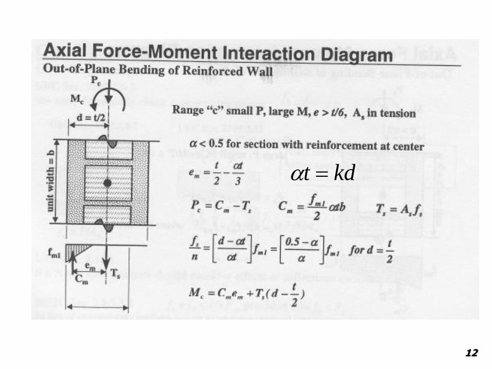
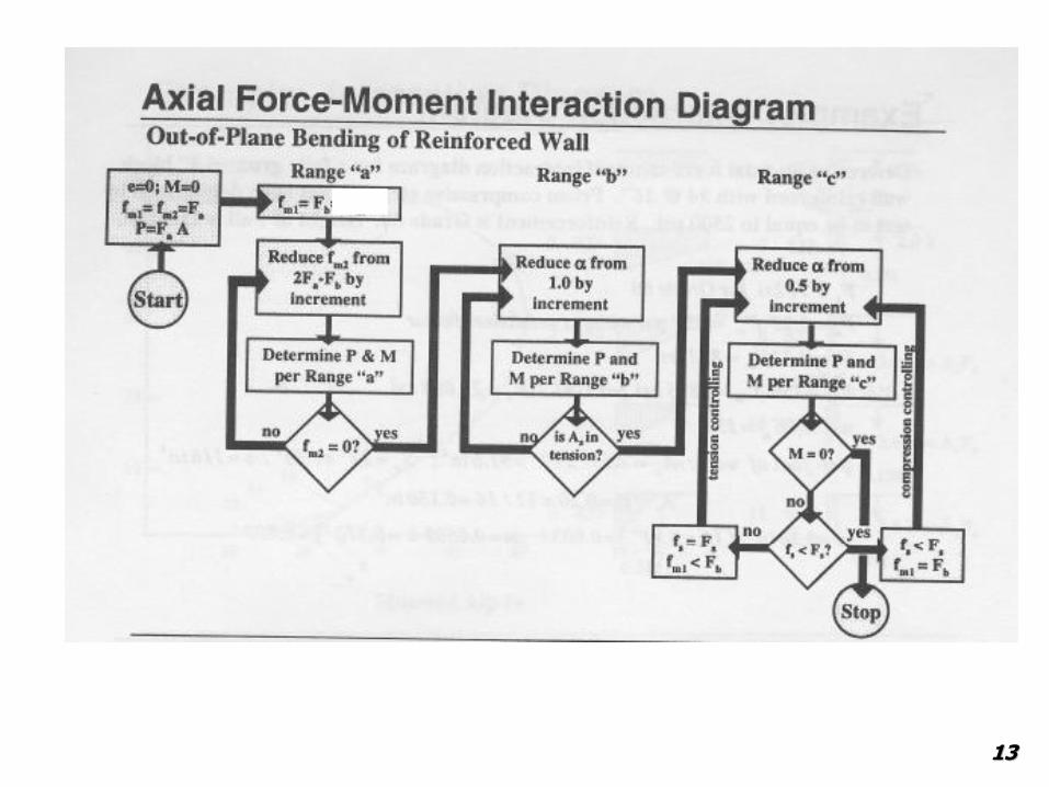
Allowable – Stress Interaction Diagrams Walls
9

Get equivalent force couple at Centerline of wall thickness
10

11
kdt
12
kdt
13

14

Allowable – Stress Interaction Diagrams Walls
Example 1(10.4-2 & 10.4-3 & 10.4-4 MDG)
8” CMU with #5 @ 48 in OC
f’m = 2000 psi Based on Effective width = 48 in., h=16.7 ft
For M = 0 , P cutoff - Equation 8-21 or 8-22
No. 5bars
centered(typ.)
d=3.81”48”
15
kips4.26429,26
2.2140
67.1610in.84in.7.63psi000,225.0
140165.0'25.0
2
2
lb
r
hFAAfP sstnma
999.90.in 20.2
in./ft12ft67.16
r
h

Spreadsheet for calculating allowable-stress M-N diagram for solid masonry wall
16.67 Ft Wall w/ No. 5 @ 48in (Centered) NOTE BASED ON 1 ft of Wall and Not EFFECTIVE WIDTH
total depth, t 7.625 Wall Height, h 16.67 feet
f'm, fprimem 2000 Radius of Gyration, r 2.20 in
Em 1800000 h/r 90.9
Fb 900.00 Reduction Factor, R 0.578
Es 29000000 Allowable Axial Stress, Fa 289 psi
Fs 32000 Net Area, An 365.7 in 2̂
d 3.8125 Allowable Axial Compr, Pa 26429 lb
kbalanced 0.311828
tensile reinforcement, As/beff 0.31 #5 @ 48 Centered
width, beff 48
because compression reinforcement is not tied, it is not counted
k kd fb Cmas fs Axial Force Moment
(psi) (lb) (psi) (lb) (lb-in)
Points controlled by steel 0.01 0.04 20 18 -32000 -2475 17
0.05 0.19 105 478 -32000 -2360 448
0.1 0.38 221 2019 -32000 -1975 1861
0.15 0.57 351 4811 -32000 -1277 4356
0.2 0.76 497 9087 -32000 -208 8084
0.25 0.95 662 15145 -32000 1306 13232
0.24 0.92 627 13774 -32000 963 12078
0.3 1.14 851 23366 -32000 3362 20044
Points controlled by masonry 0.311828 1.19 900 25679 -32000 3940 21931
0.4 1.53 900 32940 -21750 6549 27210
0.5 1.91 900 41175 -14500 9170 32704
0.6 2.29 900 49410 -9667 11603 37675
0.8 3.05 900 65880 -3625 16189 46047
1 3.81 900 82350 0 20588 52327
1.2 4.58 900 98820 0 24705 56513
1.4 5.34 900 115290 0 28823 58606
1.6 6.10 900 131760 0 32940 58606
1.8 6.86 900 148230 0 37058 56513
2 7.63 900 164700 0 41175 52327
Pure compression 900 329400 0 329400 0
Axial Force Limits 26429 0
26429 58606
kd
fb
Fs/n
kd
fb
Fb= 0.25 f’mR+?
fs 16
11.162000900
000,000,29
m
s
E
En

17
psi 22138.038.081.3
11.16
000,32
kdkdd
n
F
f
s
b
d
lb 019,24838.02212/12/1 bkdfbCmas
walloffoot per lb 1975- -7901 1/4 wallofft 1for bFor
lb 901,7)000,3231.0(2019)(
eff
Ssmas FACP
walloffoot per lb.in 1,860 7437 1/4 wallofft 1for bFor
lb.in 437,7)0(3
38.0
2
625.72019
)2
(
eff
s
ssmmas
TM
tdTeCM

18
psif
f
kdkdd
n
f
F
s
ss
b
750,21
psi 90053.153.181.3
11.16
d
lb 940,324853.19002/12/1 bkdFC bmas
walloffoot per lb 6549 198,62 1/4 wallofft 1for bFor
lb 198,26)750,2131.0(940,32)(
eff
Ssmas FACP
walloffoot per lb.in 27,200 702,108 1/4 wallofft 1for bFor
lb.in 702,108)0(3
53.1
2
625.732940
)2
(
eff
s
ssmmas
TM
tdTeCM
kd
Fb
fs/n

19
lb 350,824881.39002/12/1 bkdFC bmas
walloffoot per lb 20,587 350,82 1/4 wallofft 1for bFor
lb 350,82)031.0(350,82)(
eff
Ssmas FACP
walloffoot per lb.in 52,300 209170 1/4 wallofft 1for bFor
lb.in 170,209)0(3
81.3
2
625.7350,82
)2
(
eff
s
ssmmas
TM
tdTeCM

Spreadsheet for calculating allowable-stress M-N diagram for solid masonry wall
16.67 Ft Wall w/ No. 5 @ 48in (Centered) NOTE BASED ON 1 ft of Wall and Not EFFECTIVE WIDTH
total depth, t 7.625 Wall Height, h 16.67 feet
f'm, fprimem 2000 Radius of Gyration, r 2.20 in
Em 1800000 h/r 90.9
Fb 900.00 Reduction Factor, R 0.578
Es 29000000 Allowable Axial Stress, Fa 289 psi
Fs 32000 Net Area, An 365.7 in 2̂
d 3.8125 Allowable Axial Compr, Pa 26429 lb
kbalanced 0.311828
tensile reinforcement, As/beff 0.31 #5 @ 48 Centered
width, beff 48
because compression reinforcement is not tied, it is not counted
k kd fb Cmas fs Axial Force Moment
(psi) (lb) (psi) (lb) (lb-in)
Points controlled by steel 0.01 0.04 20 18 -32000 -2475 17
0.05 0.19 105 478 -32000 -2360 448
0.1 0.38 221 2019 -32000 -1975 1861
0.15 0.57 351 4811 -32000 -1277 4356
0.2 0.76 497 9087 -32000 -208 8084
0.25 0.95 662 15145 -32000 1306 13232
0.24 0.92 627 13774 -32000 963 12078
0.3 1.14 851 23366 -32000 3362 20044
Points controlled by masonry 0.311828 1.19 900 25679 -32000 3940 21931
0.4 1.53 900 32940 -21750 6549 27210
0.5 1.91 900 41175 -14500 9170 32704
0.6 2.29 900 49410 -9667 11603 37675
0.8 3.05 900 65880 -3625 16189 46047
1 3.81 900 82350 0 20588 52327
1.2 4.58 900 98820 0 24705 56513
1.4 5.34 900 115290 0 28823 58606
1.6 6.10 900 131760 0 32940 58606
1.8 6.86 900 148230 0 37058 56513
2 7.63 900 164700 0 41175 52327
Pure compression 900 329400 0 329400 0
Axial Force Limits 26429 0
26429 58606
MDG
kd
fb
Fs/n
kd
fb
Fb= 0.25 f’mR+?
fs 20

Ex 1 -P = 1000 lb/ft
e = 2.48 in
Roof/floor
Diaphragm
Supports Wall
3.33’
16.67’
30 psf
If P = all dead load
Check .6D + .6W at mid-height
Would also have check other load combos
0.6D + .6W at mid-height often governs
Per foot of wall analysis
P at mid-height including weight of wall
P= 987 lb/ft (0.6 D)
and M = 7,425 lb.in/ft (0.6D+0.6W)
You would need to look at other load cases
and at the top of the wall.
Also Check shear – won’t govern.
21

0.6D+0.6W
22
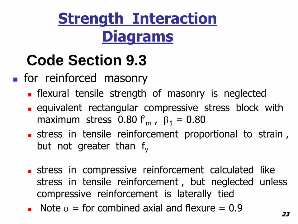
Strength Interaction Diagrams
for reinforced masonry
flexural tensile strength of masonry is neglected
equivalent rectangular compressive stress block with maximum stress 0.80 fm , 1 = 0.80
stress in tensile reinforcement proportional to strain , but not greater than fy
stress in compressive reinforcement calculated like stress in tensile reinforcement , but neglected unless compressive reinforcement is laterally tied
Note f = for combined axial and flexure = 0.9
Code Section 9.3
23

Strength Interaction Diagrams . . .
vary strain ( stress ) gradient and position of neutral axis to generate combinations of P and M – using max stress in masonry = 0.8 f’m over a compression block and max steel stress = fy
Also limit Pu applied to ≤f Pn - Eq 9-19 and Eq 9-20
99for 70
))(80(.8.0
99 for 140
1))(80(.8.0
2
'
2
'
r
h
h
rfAAAfP
r
h
r
hfAAAfP
yststnmn
yststnmn
R
R
Eq 9-19
Eq 9-20
24
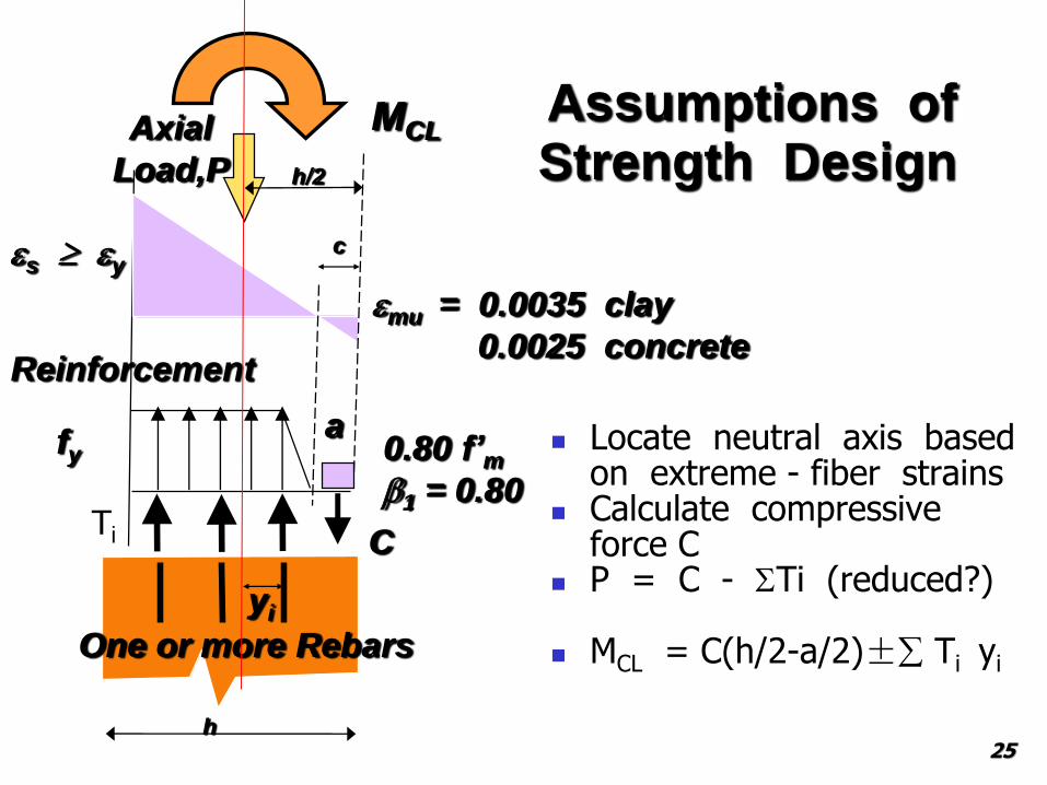
Locate neutral axis based on extreme - fiber strains
Calculate compressive force C
P = C - Ti (reduced?)
MCL = C(h/2-a/2)± Ti yi
mu = 0.0035 clay
0.0025 concrete
s y
fy
Reinforcement
Axial
Load,P
0.80 f’m1 = 0.80
Assumptions of Strength Design
MCL
Ti C
c
One or more Rebars
a
yi
h
h/2
25

Strength Interaction Example
vary c / d from zero to a large value when c = cbalanced , steel is at yield strain , and
masonry is at its maximum useful strain
when c < cbalanced , fs = fy when c > cbalanced , fs < fy
Compute nominal axial force and moment f Pn = f fi f Mn = f fi x yi ( measured from centerline )
f = 0.9
Can do hand Calc. method like before
26

Design of Walls for Out-of–Plane Loads: TMS 402 Section 9.3.5FOR SD MUST ALSO
Limit Maximum reinforcement by 9.3.3.5
Check Nominal shear strength by 9.3.4.1.2
Add P Delta Effects to Applied moments
Three procedures for computing out – of –plane moments and deflections - Load Side
Second – order analysis - Computer
Moment magnification method (new)
Complementary moment method; additional moment from P – δ effects – Slender wall analysis
27

Design of Walls for Out-of–Plane Loads: TMS 402 Section
9.3.5.4.3
Moment Magnification all loads
Mu < Mcr: Ieff = 0.75In
Mu ≥ Mcr: Ieff = Icr
)339(
)329(
1
1
)319(
2
2
0,
h
IEP
P
P
MM
effm
e
e
u
uu
28

Design of Walls for Out-of–Plane Loads: TMS 402 Section 9.3.5.4.2
Complementary Moment – Iterative? For Pu/Ag≤ 0.2 f’m
Eq. 9-29 for Mu < Mcr
Eq. 9-30 for Mu ≥ Mcr
Also Limited to h/t 30 other wise P limited to 0.05f’mAn
)309(
48
5
48
5
)299( 48
5
)289(
)279(28
22
2
2
crm
cru
nm
cru
nm
uu
ufuwu
uuu
ufu
u
IE
hMM
IE
hM
IE
hM
PPP
Pe
Phw
M
29

Design of Walls for Out-of–Plane Loads: TMS 402 Section 9.3.5.4.2
Or Solve Equations for Mu - 2 eq. 2 unknowns
Mu < Mcr
Mu ≥ Mcr
48
51
282
2
nm
u
uuf
u
u
IE
hP
eP
hw
M
crm
u
crnm
ucruuf
u
u
IE
hP
IIE
hPMeP
hw
M
48
51
11
48
5
282
22
30
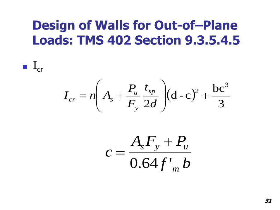
Design of Walls for Out-of–Plane Loads: TMS 402 Section 9.3.5.4.5
Icr
3
bcc-d
2
32
d
t
F
PAnI
sp
y
uscr
bf
PFAc
m
uys
'64.0
31

Design of Walls for Out-of–Plane Loads: Design Procedure
Estimate amount of reinforcement from the following equations.
This neglects P – δ effects. Can estimate increase in moment, such as 10%, for a preliminary estimate of amount of reinforcement.
Or take max moment and d-a/2 ~ .9 dAsFy =Mu
bf
MtdPdda
m
uu
8.0
2/22
f
y
ums
f
PbafA
f/8.0
32

DESIGN of REINF MASONRY WALLS Strain Diagrams
Find c balanced
For c values less than the balanced value steel yields before ult. strain in masonry
for c above the balanced value steel does not yield at ult. strain in masonry
33

DESIGN of REINF MASONRY WALLS Strain Diagrams
For c values less than the balanced value, steel yields before ult. strain in masonry
Note 1 = 0.8 in masonry
& f = 0.9
34

DESIGN of REINF MASONRY WALLS Strain Diagrams
For c values greater than the balanced value, steel does not yield before ult. strain in masonry
Note 1 = 0.8 in masonry
& f = 0.935

DESIGN of REINF MASONRY WALLS Example 2
36

DESIGN of REINF MASONRY WALLS MDG Examples DPC 2 SD
Got SD loads
See example
Then guessed
As to use
Take max.
Moment and back calculated
Asreq
37

Develop ID21 ft solid 8 in CMU #5 @ 16"
Spreadsheet for calculating SD moment-axial force interaction diagram for solid masonry wall
reinforcement at mid-depth
specified thickness 7.625 in. Wall Height, h 21.0 feet
e mu 0.0025 Radius of Gyration, r 2.20 in
f' m 2,000 psi h/r 114.5
f y 60,000 psi Reduction Factor, R 0.373
E s 29,000,000 psi
d 3.81 in. Net Area, An 91.5
(c/d )balanced 0.547 Peak Axial Compr,f P a 39,265
tensile reinforcement area 0.2325 No. 5 @ 16 in.
effective width 12 in.
phi 0.9
because compression reinforcement is not laterally supported , it is not counted
c/d c C mas f s Moment Axial Force
lb psi (ΦM n , lb-in) (ΦPn , lb)
Points controlled 0.01 0.0381 585 -60,000 1,969 -12,028
by steel 0.15 0.5715 8,778 -60,000 28,283 -4,655
0.20 0.762 11,704 -60,000 36,918 -2,021
0.30 1.143 17,556 -60,000 52,985 3,246
0.32 1.21158 18,610 -60,000 55,707 4,194
0.33 1.2573 19,312 -60,000 57,492 4,826
0.4 1.524 23,409 -60,000 67,447 8,513
Balanced point 0.547169811 2.084717 32,021 -60,000 85,810 16,264
0.80 3.048 46,817 -18,125 109,261 38,343
Points controlled 0.90 3.429 52,669 -8,056 115,701 45,717
by masonry 1.10 4.191 64,374 0 123,758 57,936
1.3 4.953 76,078 0 125,390 68,470
1.6 6.096 93,635 0 115,797 84,271
1.8 6.858 105,339 0 101,375 94,805
2.1 8.001 122,895 0 67,702 110,606
2.5 9.525 146,304 0 329 131,674
Maximum 0.05f'm 9,150
Maximum 0.2 f'm 36,600 M P
P max 0 39,265
125,390 39,265
0.2 f 'm 0 36,600
125,390 36,600
38

Develop ID
39
steel controls
walloffoot per lb 566,17
1220008.143.18.0'8.08.0
bfcC mmas
walloffoot per lb 3,245 lb ,6063 0.9 P
3606))000,602325.0(556,17()(
n
f
lbFACP ysmas
walloffoot per lb.in 985,52 walloffoot per lb.in 58,872
)2
143.1)8(.
2
626.7(17655
2
625.7
2
625.702325.060000
)22
()2
( 1
M
M
chC
hdTM mas
f

Develop ID21 ft solid 8 in CMU #5 @ 16"
Spreadsheet for calculating SD moment-axial force interaction diagram for solid masonry wall
reinforcement at mid-depth
specified thickness 7.625 in. Wall Height, h 21.0 feet
e mu 0.0025 Radius of Gyration, r 2.20 in
f' m 2,000 psi h/r 114.5
f y 60,000 psi Reduction Factor, R 0.373
E s 29,000,000 psi
d 3.81 in. Net Area, An 91.5
(c/d )balanced 0.547 Peak Axial Compr,f P a 39,265
tensile reinforcement area 0.2325 No. 5 @ 16 in.
effective width 12 in.
phi 0.9
because compression reinforcement is not laterally supported , it is not counted
c/d c C mas f s Moment Axial Force
lb psi (ΦM n , lb-in) (ΦPn , lb)
Points controlled 0.01 0.0381 585 -60,000 1,969 -12,028
by steel 0.15 0.5715 8,778 -60,000 28,283 -4,655
0.20 0.762 11,704 -60,000 36,918 -2,021
0.30 1.143 17,556 -60,000 52,985 3,246
0.32 1.21158 18,610 -60,000 55,707 4,194
0.33 1.2573 19,312 -60,000 57,492 4,826
0.4 1.524 23,409 -60,000 67,447 8,513
Balanced point 0.547169811 2.084717 32,021 -60,000 85,810 16,264
0.80 3.048 46,817 -18,125 109,261 38,343
Points controlled 0.90 3.429 52,669 -8,056 115,701 45,717
by masonry 1.10 4.191 64,374 0 123,758 57,936
1.3 4.953 76,078 0 125,390 68,470
1.6 6.096 93,635 0 115,797 84,271
1.8 6.858 105,339 0 101,375 94,805
2.1 8.001 122,895 0 67,702 110,606
2.5 9.525 146,304 0 329 131,674
Maximum 0.05f'm 9,150
Maximum 0.2 f'm 36,600 M P
P max 0 39,265
125,390 39,265
0.2 f 'm 0 36,600
125,390 36,600
40

Develop ID
41
Masonry controls
walloffoot per lb 669,52
1220008.429.38.0'8.08.0
bfcC mmas
walloffoot per lb 45,716 lb 50796 0.9 P
796,50))80562325.0(669,52()(
056,800278.0000,000,29
000278.0429.3
429.381.30025.0
n
f
lbFACP
psifs
c
cd
ssmas
mus
walloffoot per lb.in 600,115 walloffoot per lb.in 128,428
)2
429.3)8(.
2
626.7(52669
2
625.7
2
625.702325.0056,8
)22
()2
( 1
M
M
chC
hdTM mas
f

Develop ID
Get all the points and cut off any above max P
Also calc.
0.05f’mAn and
0.2f’mAn
These are cutoffs for P-D methods
21 ft solid 8 in CMU #5 @ 16"
Spreadsheet for calculating SD moment-axial force interaction diagram for solid masonry wall
reinforcement at mid-depth
specified thickness 7.625 in. Wall Height, h 21.0 feet
e mu 0.0025 Radius of Gyration, r 2.20 in
f' m 2,000 psi h/r 114.5
f y 60,000 psi Reduction Factor, R 0.373
E s 29,000,000 psi
d 3.81 in. Net Area, An 91.5
(c/d )balanced 0.547 Peak Axial Compr,f P a 39,265
tensile reinforcement area 0.2325 No. 5 @ 16 in.
effective width 12 in.
phi 0.9
because compression reinforcement is not laterally supported , it is not counted
c/d c C mas f s Moment Axial Force
lb psi (ΦM n , lb-in) (ΦPn , lb)
Points controlled 0.01 0.0381 585 -60,000 1,969 -12,028
by steel 0.15 0.5715 8,778 -60,000 28,283 -4,655
0.20 0.762 11,704 -60,000 36,918 -2,021
0.30 1.143 17,556 -60,000 52,985 3,246
0.32 1.21158 18,610 -60,000 55,707 4,194
0.33 1.2573 19,312 -60,000 57,492 4,826
0.4 1.524 23,409 -60,000 67,447 8,513
Balanced point 0.547169811 2.084717 32,021 -60,000 85,810 16,264
0.80 3.048 46,817 -18,125 109,261 38,343
Points controlled 0.90 3.429 52,669 -8,056 115,701 45,717
by masonry 1.10 4.191 64,374 0 123,758 57,936
1.3 4.953 76,078 0 125,390 68,470
1.6 6.096 93,635 0 115,797 84,271
1.8 6.858 105,339 0 101,375 94,805
2.1 8.001 122,895 0 67,702 110,606
2.5 9.525 146,304 0 329 131,674
Maximum 0.05f'm 9,150
Maximum 0.2 f'm 36,600 M P
P max 0 39,265
125,390 39,265
0.2 f 'm 0 36,600
125,390 36,600
42

Develop ID
Plot ID
43

Add P-D effects to applied Moments – Complementary Method or Moment Magn. methods
Complementary Method )279(28
2
uuu
ufu
u Pe
Phw
M
Or Solve Equations for Mu - 2 eq. 2 unknowns
Mu < Mcr
Mu ≥ Mcr
48
51
282
2
nm
u
uuf
u
u
IE
hP
eP
hw
M
crm
u
crnm
ucruuf
u
u
IE
hP
IIE
hPMeP
hw
M
48
51
11
48
5
282
22
44

Add P-D effects to applied Moments – Complementary Method or Moment Magn. methods
Moment Mag. Method
33)(9
32)(9
1
1
)319(
2
2
0,
h
IEP
P
P
MM
effm
e
e
u
uu
wallof kips.in/ft 14.6 moment order first uM
1.2D+1.6Lr+0.5W load combination
45
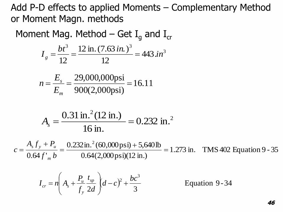
Add P-D effects to applied Moments – Complementary Method or Moment Magn. methods
Moment Mag. Method – Get Ig and Icr
333
.44312
) . 63.7( in. 12
12in
inbtI g
11.16)psi000,2(900
psi000,000,29
m
s
E
En
22
in. 232.0in. 16
)in. 12(in. 31.0sA
34-9Equation 32
32 bc
cdd
t
f
PAnI
sp
y
uscr
35-9Equation 402 TMS in. 273.1)in. 12)(psi000,2(64.0
lb640,5)psi000,60(in.232.0
'64.0
2
bf
PfAc
m
uys
46
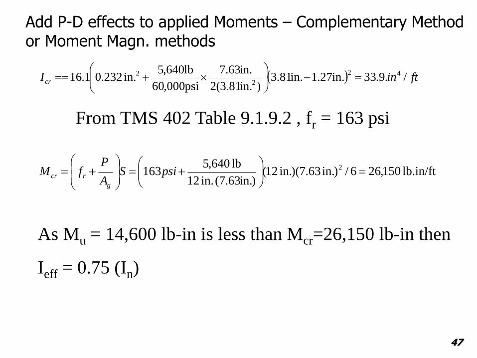
Add P-D effects to applied Moments – Complementary Method or Moment Magn. methods
ftinIcr /.9.33in.27.1in.81.3)in.81.3(2
in.63.7
psi000,60
lb640,5in. 232.01.16 42
2
2
From TMS 402 Table 9.1.9.2 , fr = 163 psi
lb.in/ft 150,266/)in. 63.7)(in. 12()in.63.7( in. 12
lb 640,5163 2
psiS
A
PfM
g
rcr
As Mu = 14,600 lb-in is less than Mcr=26,150 lb-in then
Ieff = 0.75 (In)
47

Add P-D effects to applied Moments – Complementary Method or Moment Magn. methods
lb 93,000 )in./ft 12ft 21(
)75.0)(in443)(psi000,2(900
2
42
2
2
h
IEP
effm
e
06.1
lb 000,93
lb 640,51
1
1
1
e
u
P
P
Mu = 1.06 (14.6 kip.in/ft) =15.5 kip.in/ft which is still
below the capacity envelope
Check other Load cases48

Develop ID
Plot ID
49

DESIGN of REINF MASONRY WALLS - Out of Plane loads –Axial and flexure
Must check Max Reinforcing 9.3.3.5 Comm.
y
ymu
mum
f
bd
Pf
'64.0
max
P load D + 0.75 L + 0.525 Qe load combination and = 1.5 for walls loaded OOP. The force per foot of wall is:P = (11,900 lb/4 + 1,190 lb)+ 0.75×11,500 lb/4 + 0.525×3,330 lb/4 = 6,760 lb
50

DESIGN of REINF MASONRY WALLS - Out of Plane loads –Axial and flexure
Must check Max Reinforcing 9.3.3.5 Comm.
This would allow an area of steel of up to As = 0.00705 × 12 in. × 3.81 in. = 0.322 in2
per foot of wall, which is more than 0.233 in2/ft provided using No. 5 bars at 16 in. on center.
00705.psi000,60
in. 81.3in. 12
lb760,6
00207.05.10025.0
0025.0psi 000,264.0
max
51

DESIGN of REINF MASONRY WALLS - Out of Plane loads –Axial and flexure
Should check shear but never a problem out of plane for LB and non LB walls.
52

DESIGN of REINF MASONRY WALLS - Out of Plane loads – Axial and flexure -
How high can you go?
53

For this Loading
54
P = 1000 lb/ft L , 500lb/ft D
e = 2 in
Roof/floor
Diaphragm
Supports Wall
30 psf
h=?

8” CMU
55
ASD
H = 30 ft
# 6 bars at
16” on center
d = 3.81”
fully grouted
8” CMU
f’m = 2000 psi
ASD design
No. 6 bars
centered(typ.)
d=3.81”16”

How high - 8” CMU?
56
ASD H = 39 ft
# 6 bars at 16” on
Staggered d = 5”
fully grouted 8” CMU
f’m = 2000 psi
ASD design
No. 6 bars Staggered (typ.)
d=5”
16”

8” CMU
57
SD
H = 30 ft
# 6 bars at
16” on center
d = 3.81”
fully grouted
8” CMU
f’m = 2000 psi
SD design
No. 6 bars
centered(typ.)
d=3.81”16”
Be careful with fr – Very slender walls -
use complementary Method and
account for P/A for Cracking moment

Try 12” CMU
58
ASD H = 44.5 ft
# 6 bars at 16” on
Centered d = 5.81”
fully grouted 12”
CMU
f’m = 2000 psi
ASD design
No. 6 bars Staggered (typ.)
d=5.81”
16”

Try 12” CMU
59
ASD H = 55 ft
# 6 bars at 16” on
Centered d =
5.81”
fully grouted 12”
CMU
f’m = 2000 psi
ASD design
59
No. 6 bars Staggered (typ.)
d=8.75”
16”

Summary
Over view of Single wythe walls
Presented ASD Reinforced Masonry Wall Design Provisions
Presented SD Code provisions Masonry Wall Design Provisions
Presented Wall Design Examples
60

J.B
. S
PE
ED
SC
HO
OL
OF
EN
GIN
EE
RIN
G
61
THANK YOU !
QUESTIONS?