designing a battery-based system...
TRANSCRIPT

Designing a Battery-Based System Step-by-Step
Brian Teitelbaum
Application Engineer
Tuesday, January 19, 2016
San Diego, CA

Introduction
• Disclaimer
AEE Solar is a distributor of goods and services used in the deployment of PV and wind distributed power systems. We are not accountants, attorneys or Code-making experts. The information presented here represents the equipment, rules and best practices that we are aware of. However, local and project-specific requirements can vary widely.

Types of Battery-Based Systems
PV/wind direct• Loads are run directly from renewable energy source • No energy storage (batteries)• Loads typically motors (pumps, fans, etc.) that run directly from the
energy source
DC-Only • All loads run on DC from a battery• Batteries charged by PV, wind turbine, generator, etc.
AC-only• All loads run on AC power from an inverter or AC generator • Most common type of Off-Grid system used for homes
AC/DC• Both AC and DC loads are powered by the system
Hybrid• Derives energy from more than one source• i.e. PV and wind, PV and utility grid, or PV and a generator
Designing a Battery-Based System Step-by-Step
System Sizing

User Data You Will Need to Collect
• Daily consumption (Watt-hours)‒ How much energy will the application consume each day? Is it seasonal?
‒ For each load, multiply the power draw by the hours it is used per day
‒ For appliances, divide the Energy Star annual consumption kWh by 365
‒ http://www.energystar.gov/index.cfm?c=products.pr_find_es_products
• Peak load (Watts) and characteristics (VDC/VAC/Hz)‒ Sum of all loads that may be run simultaneously
‒ Separate AC and DC Loads
‒ Voltage and frequency the loads require
• Days of Autonomy‒ How many days in a row will the loads need to run with little or no sun
‒ Don’t neglect heavy snows
• Sun-Hours per day during darkest month (kWh/day)‒ This is the available solar resource
‒ Use Winter Solstice time frame rather than annual average if loads will be run during winter

Load Analysis
• Load Worksheet –
‒ 2016 AEE Solar Design Guide and Catalog – Page 9

Don’t Forget “Stand-by” Loads
123.5W X 24hrs = 2964Wh = 3kWh/day

System Options You Will Need to Choose
• Battery Type: Flooded, AGM, Gel or Advanced‒ Consider: Maintenance, shipping and storage requirements
• Battery bank DC voltage : 12, 24, 48 VDC (or high-voltage)‒ Consider: Voltage of DC loads, size of system, available inverters
‒ 48VDC is generally most efficient and cost-effective for AC systems over 2kW
• Charge controller type: PWM or MPPT
‒ Pulse Width Modulated (PWM) controllers
Pros: Inexpensive and compact
Cons: Low capacity (up to 60A), input voltage limitations (12/24/48VDC array)
‒ Maximum Power Point Tracking (MPPT) controllers
Pros: Maximized energy harvest, wider input voltage range (48 to 600VDC), higher capacity (up to 100A)
Cons: More Expensive , physically larger
• Module Type: 36-cell, 60-cell or 72-cell‒ PWM controllers require 36-cell (12 VDC nominal) or 72-cell (24 VDC nominal)
modules
‒ Consider transportation and mounting limitations as well as module cost per watt
PV Array Sizing for Off-Grid Systems
• PV arrays for Off-Grid systems are based on the peak sun-hours during the darkest month of the year, not the yearly average
• Most Off-Grid systems require some sort of back-up power, usually a generator, for extended cloudy weather.

PV Array Sizing Peak Sun-Hours
NREL Red Book

PV Array Sizing Peak Sun-Hours

PV Array Sizing Peak Sun-Hours
AEE Solar Catalog Maps
• In Reference Section in the back of the Catalog
• These maps show the Peak Sun-Hours for the darkest month of the year
• NOT the yearly average
• They are useful for sizing off-grid systems, not grid-tie systems

PV Array Sizing For PWM Controllers
• Find the current the array must produce
𝐷𝑎𝑖𝑙𝑦 𝑐𝑜𝑛𝑠𝑢𝑚𝑝𝑡𝑖𝑜𝑛 (𝐴ℎ) × 1.2
𝑘𝑊ℎ 𝑝𝑒𝑟 𝑚2𝑝𝑒𝑟 𝑑𝑎𝑦= 𝑅𝑒𝑞𝑢𝑖𝑟𝑒𝑑 𝐴𝑟𝑟𝑎𝑦 𝐴𝑚𝑝𝑠
• Select a PV module
‒ Find the peak current rating (Imp) on the module data sheet
• Determine the number of parallel strings required
𝑅𝑒𝑞𝑢𝑖𝑟𝑒𝑑 𝐴𝑟𝑟𝑎𝑦 𝐴𝑚𝑝𝑠
𝑀𝑜𝑑𝑢𝑙𝑒 𝐼𝑚𝑝= 𝑇𝑜𝑡𝑎𝑙 𝑠𝑡𝑟𝑖𝑛𝑔𝑠
• Determine the number of modules per string
12 VDC modules (36-cell) : 12 VDC system = 1 per string24 VDC system = 2 per sting
24 VDC modules (72-cell) : 12 VDC system = NA24 VDC system = 1 per string
• Determine the total number of modules
𝑇𝑜𝑡𝑎𝑙 𝑠𝑡𝑟𝑖𝑛𝑔𝑠 × 𝑆𝑡𝑟𝑖𝑛𝑔 𝑙𝑒𝑛𝑔𝑡ℎ = 𝑇𝑜𝑡𝑎𝑙 𝑚𝑜𝑑𝑢𝑙𝑒𝑠
12 VDC10 A
24 VDC5 A

MPPT Charge Controllers
• Charge controllers for modern 60 cell modules must be MPPT type
‒ MPPT = Maximum Power Point Tracking
• An MPPT controller will convert the input voltage to the correct voltage for charging the battery
• Array voltage must be higher than the battery voltage
• MPPT Charge controllers are current limited
A 4kW array will need one 80 A change controller for a 48 VDC battery, but will require two controllers for a 24 VDC battery
80 A x 48 VDC = 3,840 W80 A x 24 VDC = 1,920 W
• The PV array will rarely put out full rated power except at high altitude sites
‒ Reasonable oversizing of array vs. charge controller can minimize cost
‒ Always have overcurrent protection between array and controller

Charge Controllers String Sizing (MPPT)
• String operating voltage must be between battery charging voltage and controller limit (usually 150 VDC)
‒ Power will drop off dramatically if the charge point of the array falls below the battery voltage
• A 48 VDC battery charges at 56 VDC or more
Requires at least three 60-cell modules to charge correctly
2 modules x 27 VDC = 54 VDC
2 modules in series will typically not charge a 48 VDC battery at full power in hot weather
• Most 60 cell modules will exceed 150 VDC in strings of 4 in most locations
• A 48 VDC battery requires 3 modules in series only
• A 24 VDC battery can typically use either 2 or 3 modules in series

PV Array Combiner Boxes
• Each parallel string of modules must have circuit protection
‒ Most modules have a 15 A circuit rating
‒ Under fault conditions, the array can be exposed to full short circuit current of the battery bank
• The breakers in these circuits must be rated for the maximum voltage
‒ Maximum voltage for many of these systems will be 150 VDC
• High-voltage charge controllers require higher voltage breakers or fuses and a proper combiner box for them.
• All array circuits going to each charge controller must have a separate and isolated feeder to that charge controller
• Some combiner boxes have the capacity for two separate circuits
‒ Multiple combiners may be more convenient for wire management

Balance of System: Charge Controller Circuit Protection
• Disconnects and circuit protection are required between the PV array and the charge controller, and between the charge controller and the battery
• A circuit breaker is normally used for 150 VDC PV input circuits to controller
‒ This breaker must be sized for 156% (125% x 125%) of Isc of array (STC)
‒ Breaker not to exceed the maximum input amperage rating for the charge controller
‒ Wire between breaker and the combiner box must meet or exceed the current rating of the breaker used
• The charge controller breaker and disconnect serves as the battery breaker
‒ If it matches the charge controller output rating it must be rated for continuous duty
‒ If not rated for continuous duty at full amperage, size to 125% of max current
‒ For OutBack systems, this is typically the GFDI breaker
‒ If the charge controller will be operated near its limit, oversize the battery breaker slightly to avoid nuisance tripping

Balance of System: Ground and Arc Fault Protection
• Ground fault detection and disconnect (GFDI) is required for most residential systems
‒ DC-GFDI or “DC-GFP” assemblies
• A DC-GFDI is simply a small breaker’s pole connected to larger breaker poles
‒ The smaller breaker pole (usually 0.5A) connects the negative array conductor to ground
‒ This connection is the DC negative-to-ground bond
‒ If the GFDI breaker trips from current flowing between negative and ground, it also disconnects the PV array and/or charge controller
• The GFDI is traditionally installed between the array breaker and charge controller
‒ OutBack also uses it between the charge controller and battery, serving as the charge controller disconnect
• The 2011 NEC code also requires Arc Fault detection in the PV system
‒ Stand-alone arc fault detectors are not available at this time

Designing a Battery-Based System Step-by-Step
Charging Batteries

Flooded Cell (Deep Cycle Type)
• Lower initial cost than VRLA in smaller sizes
• Excellent cycle life
• Electrolyte loss is replaceable
• Less sensitive to overcharging
• Not sealedo Cannot be mounted on its side
o Cannot be shipped by air
o Requires isolation & ventilation
• Maintenance requiredo Water must be added ~monthly
o Regular equalization charge
o Reduced life at higher temperatures
• Less efficient
Higher self discharge,
Much higher float current >1kWh per day likely.
• Sensitive to shock and vibration
Pros Cons
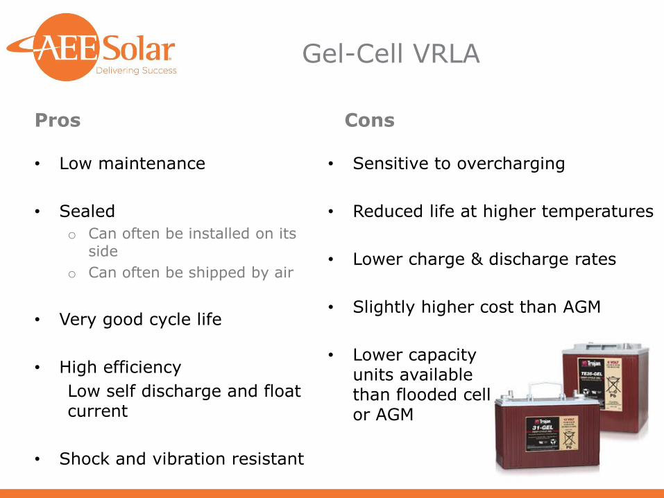
Gel-Cell VRLA
• Low maintenance
• Sealed
o Can often be installed on its side
o Can often be shipped by air
• Very good cycle life
• High efficiency
Low self discharge and float current
• Shock and vibration resistant
• Sensitive to overcharging
• Reduced life at higher temperatures
• Lower charge & discharge rates
• Slightly higher cost than AGM
• Lower capacity units available than flooded cell or AGM
Pros Cons

Absorbed Glass Mat (AGM) VRLA
• Low maintenance
• Sealedo Can be installed on its sideo Can often be shipped by air
• High efficiencyLow self discharge and float current
• Shock and vibration resistant
• Works in high-power applications
• Large capacity batteries available
• Sensitive to overcharging
• Reduced life at higher temperatures
• Electrolyte cannot be replaced
• Higher initial cost in smaller sizes than flooded
Pros Cons

AGM with Carbon
• Carbon is added to the negative plate of lead acid batteries, either sealed or flooded, to improve partial state of charge performance
• Extended partial state of charge (PSoC)
Sulfation on the negative plate is minimized
Much less need for regular full charge
Excellent for self-consumption or off-grid systems
No advantage for standby backup systems
• Longer cycle life in real conditions
‒ Can be cycled in mid state of charge
‒ Up to 44% improvement in cycle life
‒ Only about 15% higher price
• Available in AGM or Flooded
OutBack Energy Cell Nano-Carbon AGM, in a wide range of sizes
Trojan SmartCarbon flooded commercial and industrial

Aqueous Hybrid Ion (Aquion)
• High cycle life at high cycle depth
o Up to 3,000 cycles @ 100% DoD
o Up to 6,000 cycles @ 50% DoD
o Operates from -5°C to 40°C with full life
• Durable and abuse tolerant
o Completely tolerant of partial state of charge
o Self balancing in parallel strings
o Can be completely depleted without harm
o No active management necessary
• Very safe
o Limited power output to shorts
o Will not support flame
o Will not explode
o No thermal runaway issues
• Cradle to Cradle certified
o All common non-toxic materials
o Sodium, and a little Lithium, salt water electrolyte
• Moderately expensive
o 2 to 3 X price of lead-acid batteries
o Available in 48 V blocks only
• Low power and energy density
o Requires more space for the same capacity
o Wider voltage range ~40 V to 57 V
o Low rate of charge and discharge
o Limited capacity at higher rates of charge and discharge
Pros Cons

Tesla Powerwall
• High power and energy density
o 6.4 kWh daily version or 9.1 kWh weekly version
o High voltage to substantially reduce current and wire size
o Takes up little space, wall hung
• High cycle life at high cycle depth
o Up to 3,000 cycles @ 100% DoD
o High round trip efficiency up to 92.5%
o Control of thermal issues
o Use between -20°C to 50°C with internal cooling and heating
• Easy to install
o Integrates to solar inverters, SolarEdge to start
o Light weight
o Touch safe
o Outdoor rated
o Multiple units for larger capacity up to 7 units
• Pleasing design
o Decorative cover
• Moderately expensive
o 2 to 3 X price of lead-acid batteries
o May have limited calendar life ~10 years
• Availability
o Installers must complete special training and legal agreements before selling
o Limited to two parallel units to start
o Limited inverter compatibility
Pros Cons

Lithium Ion
• Widely used in laptops, EVs and handheld devices
• High power and energy density
o Discharge rates up to 40X nominal Ah capacity
o Up to ~40 Wh/lb
• High cycle life at high cycle depth
o Up to 3,000 cycles @ 80 to 90% DoD
• Expensive
o 2 to 5 X price of lead-acid batteries
o May have limited calendar life ~10 years
• Thermal management challenges
o Operates between ~32 °F and 100 °F
o Risk of thermal runaway fire or explosion
o LiFePO and related chemistries less prone to thermal runaway risk, but more expensive and less energy density
• Requires sophisticated battery management system
o Adds to cost
o Adds significant design complexity
• Non-recyclable and hazardous
o Disposal costs not typically included in price
o Shipping restrictions
o Will support combustion in a fire
Pros Cons

Nickel Based BatteriesNiCd, NiFe, NiMH
• Good energy and power density
o About 60% of Lithium-ion
• High cycle life at high cycle depth
o Up to 11,000 cycles or more @ 80% DoD for flooded NiFe
o Up to 5,000 cycles or more @ 80% DoD for flooded NiCd
• Robust
o Flooded cells only, not sealed
o No sudden failures
o Tolerant of under and overcharging
o Very wide operating temperature range
• Flat voltage vs. state of charge curve
• Less hazardous materials
• Very Expensive
o 3 - 5 X price of lead-acid batteries
o Heavy metals, Nickel and/or Cadmium
• Low cell voltage
o Low cell voltage (~1.2 VDC)
o More cells required per system
• High self-discharge rate
• Memory effect in sealed NiCd cells
o Need to fully cycle about once per month
o Limited reconditioning is possible
Pros Cons

Battery Capacity
• Capacity = Ampere-hours provided to the load(s) ‒ Changes according to discharge rate,
temperature, age, etc.
‒ 20-hour rating = 100% capacity = C20
‒ 8-hour rating = 88% of C20
‒ 6-hour rating = 84% of C20
‒ 3-hour rating = 74% of C20
‒ 1-hour rating = 59% of C20
• Batteries deliver less than 100% rated capacity when new. ‒ Poor maintenance will affect capacity
• Batteries self discharge if stored for long periods of time without being charged. ‒ The hotter the temperature the more
self discharge
Temperature vs. Capacity

Battery Wiring
• Series: Voltage is additive; capacity remains same
‒ Positive of Battery 1 is connected to negative of Battery 2 and so on
Example: Two 12 VDC, 220 Ah batteries in series will yield a 24 VDC, 220 Ah battery
• Parallel: Capacity is additive; voltage remains same
‒ The positives are connected to each other, same for negatives
‒ Output leads must be from first and last battery for electrical balance
‒ Manufacturers typically limit maximum number of parallel strings to three
Example: Two 12 VDC, 220 Ah batteries in parallel will a 12 VDC, 440 Ah battery
Series connection
Parallel connection

Battery Charging
• Lead Acid Batteries should be charged after every use to ensure they
are never stored in a discharged condition (May not be as necessary
for added Carbon batteries)
‒ If batteries are stored for extended periods of time they should be charged approximately every 6 weeks
‒ Between 105-120% of previously discharged capacity must be returned for full charge
‒ No need to fully discharge prior to charging
‒ Charging should be temperature corrected
‒ Always use charge controller’s temperature sensor when available
• Flooded Batteries need to be overcharged to ensure proper mixing of
the electrolyte and avoid stratification
‒ “Equalization” - deliberate, periodic overcharge to prevent electrolyte stratification
‒ Most charge controllers have an equalize charge setting

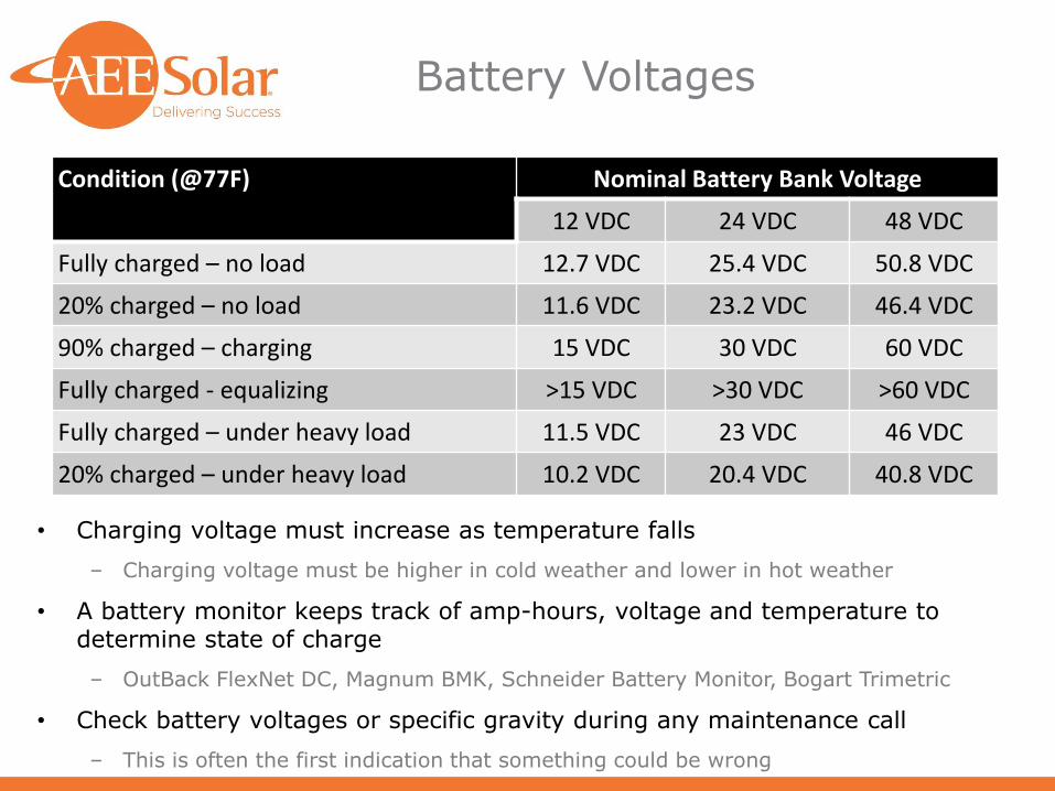
Battery Voltages
• Charging voltage must increase as temperature falls
‒ Charging voltage must be higher in cold weather and lower in hot weather
• A battery monitor keeps track of amp-hours, voltage and temperature to determine state of charge
‒ OutBack FlexNet DC, Magnum BMK, Schneider Battery Monitor, Bogart Trimetric
• Check battery voltages or specific gravity during any maintenance call
‒ This is often the first indication that something could be wrong
Condition (@77F) Nominal Battery Bank Voltage
12 VDC 24 VDC 48 VDC
Fully charged – no load 12.7 VDC 25.4 VDC 50.8 VDC
20% charged – no load 11.6 VDC 23.2 VDC 46.4 VDC
90% charged – charging 15 VDC 30 VDC 60 VDC
Fully charged - equalizing >15 VDC >30 VDC >60 VDC
Fully charged – under heavy load 11.5 VDC 23 VDC 46 VDC
20% charged – under heavy load 10.2 VDC 20.4 VDC 40.8 VDC

Depth of Discharge
• Deep Discharging will shorten battery life
• Most lead-acid batteries designed for 50% DoD
• Deep-Cycle Batteries designed for up to 80% DoD
‒Shallower cycles will enable longer life
• Never leave batteries discharged for more than 1-2 days!
‒Sulfating of electrodes will permanently decrease capacity (much less so for Nano-Carbon)

Watering Flooded Batteries
• Add distilled water to cells AFTER charging
‒ Never add acid/electrolyte to cells
‒ Fill to 1/8” below the bottom of the fill well or to maximum level indicator
• Do not overfill the batteries
• If the plates are exposed, add water to discharged batteries to just above the plates
‒ Do not fill all the way!
• Never add water to discharged batteries if the electrolyte is visible above the plates!
‒ This will cause the batteries to spill over when they are charged
• Single-point watering systems can make it much easier and safer
Be sure system is compatible with batteries used

Battery Safety
• Always wear personal protective equipment when handling batteries
‒ Chemical-resistant gloves, goggles or face shield, acid-resistant apron and boots
• Keep flames, sparks or metal objects away from batteries
‒ Use insulated tools
‒ Do not smoke near batteries
‒ No metal jewelry
• Neutralize acid spills with baking soda immediately
• Ensure that vent caps are securely in place before charging
• Provide proper ventilation to prevent gas build up
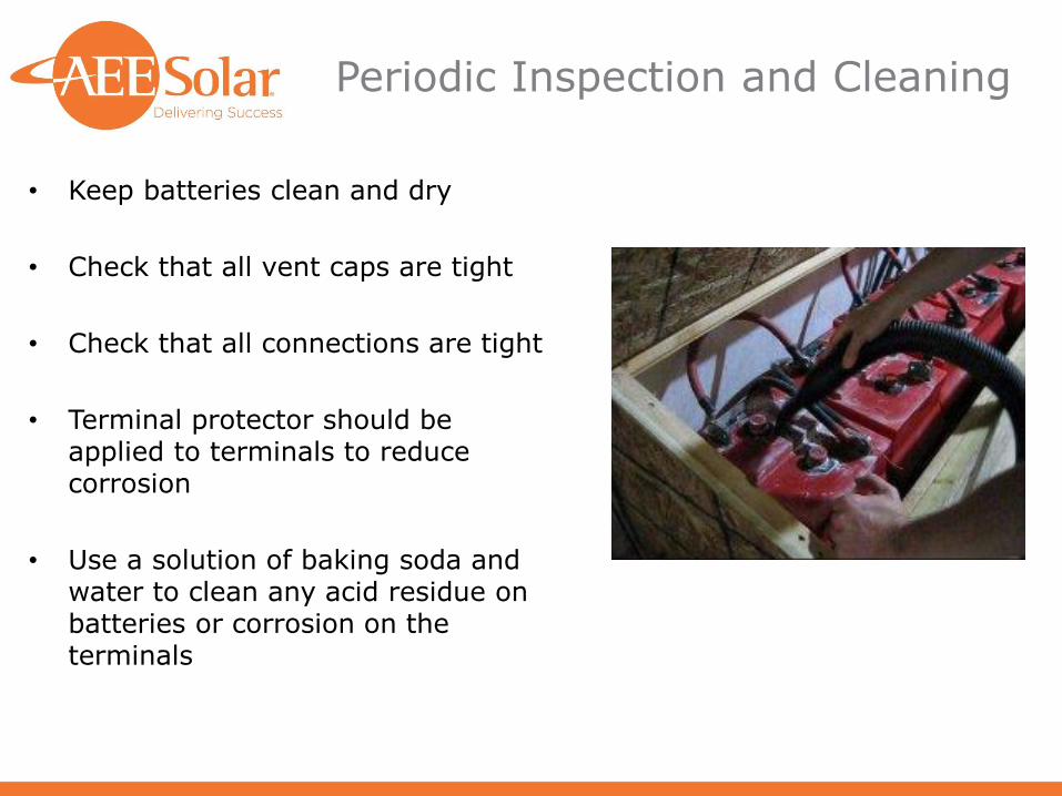
Periodic Inspection and Cleaning
• Keep batteries clean and dry
• Check that all vent caps are tight
• Check that all connections are tight
• Terminal protector should be applied to terminals to reduce corrosion
• Use a solution of baking soda and water to clean any acid residue on batteries or corrosion on the terminals

Battery Enclosures
• Batteries must be properly housed and sited
• Keep batteries in temperature-controlled space‒ Basements or garages are typical
• Battery enclosure must be ventilated‒ Active ventilation may be required for flooded
batteries in hot or tightly enclosed spaces
• Protect terminals from people, pets and falling objects
• Ensure that battery rack/enclosure meets any applicable seismic requirements for your region
• Breakers/Switches help improve safety when using and servicing batteries
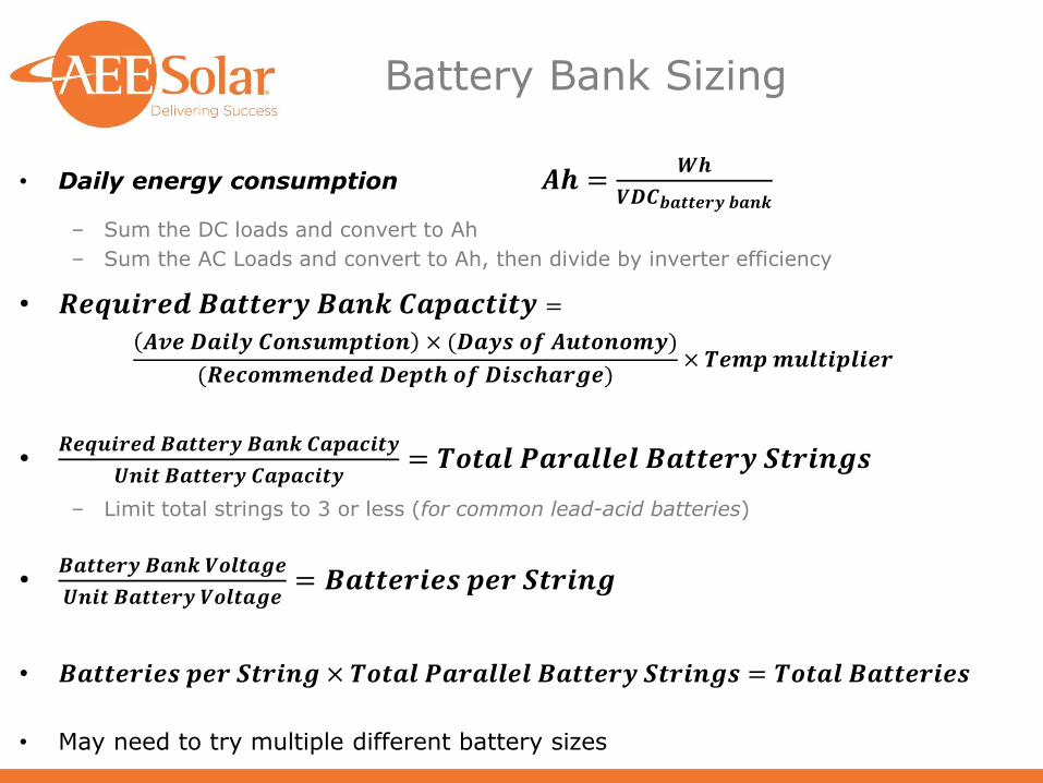
Battery Bank Sizing
• Daily energy consumption 𝑨𝒉 =𝑾𝒉
𝑽𝑫𝑪𝒃𝒂𝒕𝒕𝒆𝒓𝒚 𝒃𝒂𝒏𝒌
‒ Sum the DC loads and convert to Ah
‒ Sum the AC Loads and convert to Ah, then divide by inverter efficiency
• 𝑹𝒆𝒒𝒖𝒊𝒓𝒆𝒅 𝑩𝒂𝒕𝒕𝒆𝒓𝒚 𝑩𝒂𝒏𝒌 𝑪𝒂𝒑𝒂𝒄𝒕𝒊𝒕𝒚 =
𝑨𝒗𝒆 𝑫𝒂𝒊𝒍𝒚 𝑪𝒐𝒏𝒔𝒖𝒎𝒑𝒕𝒊𝒐𝒏 × (𝑫𝒂𝒚𝒔 𝒐𝒇 𝑨𝒖𝒕𝒐𝒏𝒐𝒎𝒚)
(𝑹𝒆𝒄𝒐𝒎𝒎𝒆𝒏𝒅𝒆𝒅 𝑫𝒆𝒑𝒕𝒉 𝒐𝒇 𝑫𝒊𝒔𝒄𝒉𝒂𝒓𝒈𝒆)× 𝑻𝒆𝒎𝒑𝒎𝒖𝒍𝒕𝒊𝒑𝒍𝒊𝒆𝒓
•𝑹𝒆𝒒𝒖𝒊𝒓𝒆𝒅 𝑩𝒂𝒕𝒕𝒆𝒓𝒚 𝑩𝒂𝒏𝒌 𝑪𝒂𝒑𝒂𝒄𝒊𝒕𝒚
𝑼𝒏𝒊𝒕 𝑩𝒂𝒕𝒕𝒆𝒓𝒚 𝑪𝒂𝒑𝒂𝒄𝒊𝒕𝒚= 𝑻𝒐𝒕𝒂𝒍 𝑷𝒂𝒓𝒂𝒍𝒍𝒆𝒍 𝑩𝒂𝒕𝒕𝒆𝒓𝒚 𝑺𝒕𝒓𝒊𝒏𝒈𝒔
‒ Limit total strings to 3 or less (for common lead-acid batteries)
•𝑩𝒂𝒕𝒕𝒆𝒓𝒚 𝑩𝒂𝒏𝒌 𝑽𝒐𝒍𝒕𝒂𝒈𝒆
𝑼𝒏𝒊𝒕 𝑩𝒂𝒕𝒕𝒆𝒓𝒚 𝑽𝒐𝒍𝒕𝒂𝒈𝒆= 𝑩𝒂𝒕𝒕𝒆𝒓𝒊𝒆𝒔 𝒑𝒆𝒓 𝑺𝒕𝒓𝒊𝒏𝒈
• 𝑩𝒂𝒕𝒕𝒆𝒓𝒊𝒆𝒔 𝒑𝒆𝒓 𝑺𝒕𝒓𝒊𝒏𝒈 × 𝑻𝒐𝒕𝒂𝒍 𝑷𝒂𝒓𝒂𝒍𝒍𝒆𝒍 𝑩𝒂𝒕𝒕𝒆𝒓𝒚 𝑺𝒕𝒓𝒊𝒏𝒈𝒔 = 𝑻𝒐𝒕𝒂𝒍 𝑩𝒂𝒕𝒕𝒆𝒓𝒊𝒆𝒔
• May need to try multiple different battery sizes

Designing a Battery-Based System Step-by-Step
Inverters:
Making AC from Batteries

Battery-Based vs. Grid-tie Inverters
• Voltage sourced
o Inverter builds its own waveform
• Fixed low-voltage input
o Inverter fed from steady 12/24/48VDC from batteries
• PV array MPPT provided by charge controller
o Charge controller dictates string size
• Modest efficiency: 75-90%
• Low-voltage single-phase 120 or 240VAC output
• Current sourced
o Inverter uses grid waveform
• Actively controlled voltage input
o Inverter uses MPPT and accepts wide range of voltages
• Inverter provides PV array MPPT
o String sizing dictated by inverter
• High efficiency: 95-98%
• Range of outputs
o 240VAC or 208/277/480VAC 3-phase
Battery-Based Inverters Grid-tie Inverters

Inverter Sizing
• Find maximum AC load
‒ Identify and sum all loads that may run simultaneously
‒ Sum up total Watts – this is the minimum inverter continuous power rating
• Identify any loads with high start-up or surge current draws
‒ Motors in compressors, fans and appliances
‒ Gauss rifles/rail guns, electromagnets and other large inductive loads
‒ Largest surge load determines minimum inverter surge rating
• Identify any loads that may require 240 VAC
‒ 240 VAC often requires transformer or dual inverters
• Be sure to consider inverter’s no-load-draw when sizing battery system and array

Inverter Selection Considerations
• Will there be an AC generator in the system?
‒ Be sure inverter has generator input for battery charging
‒ Be sure that inverter and generator are compatible
• Will the system connect to the utility grid?
‒ Inverter must be “grid interactive” – these inverters have internal transfer switches to comply with UL 1741/IEEE 1547 anti-islanding requirements
• Will the inverter be mounted outdoors?
‒ Most battery-based inverters are only rated for indoor use (NEMA 1)
• Do the loads include sensitive electronics or audio equipment?
‒ Modified sine wave inverters may damage certain electronics and will interfere with most speakers
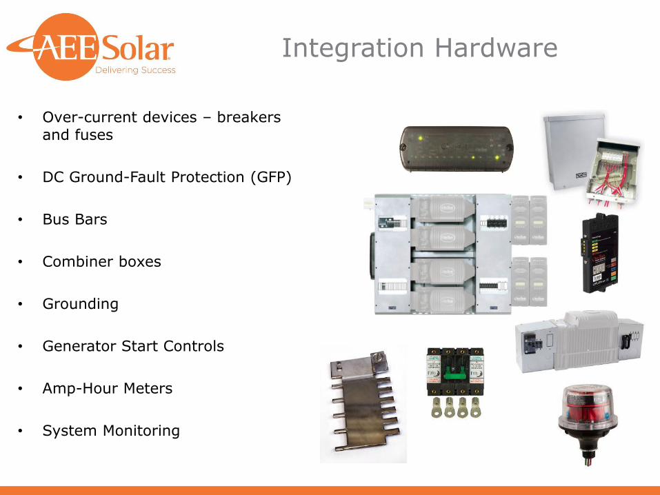
Integration Hardware
• Over-current devices – breakers and fuses
• DC Ground-Fault Protection (GFP)
• Bus Bars
• Combiner boxes
• Grounding
• Generator Start Controls
• Amp-Hour Meters
• System Monitoring

Balance of System (BOS): Power Panels

Balance of System (BOS): Power Panels
• A central location is desired to connect wiring and install breakers
• There needs to be a DC load center and an AC load center, or one load center for both AC and DC
• A battery-based inverter can have a very large current draw
• Especially when battery voltage is lower
• The main DC breaker for these inverters is 125 A to 250 A
• The inverter manufacturer or supplier will generally specify breaker sizes
• Beaker size is generally max power output in watts divided by battery voltage x 1.5, but sometimes larger
• Wire size for battery and inverter circuits will commonly be 2/0 or 4/0 AWG
• Keep connection as short as possible to minimize voltage drop
• Under 10 ft is best

Balance of System (BOS): Power Systems
• Factory pre-wired power systems are available to simplify design and installation
• Several common sizes & configurations
• Pre-wired power systems include:
• Inverter(s)
• Controller and networking devices
• Battery monitor
• Integration hardware and BOS
• Enclosures, Breakers, GFDI, Bypass, etc.
• Charge controllers

Balance of System (BOS):System Controllers
• Automate battery management
• Float and equalization charge timing
• Turn on/shut off inverters and/or generators according to time of day or battery state of charge
• Remote monitoring/control via Internet

Example: AC-Only System
• Off-Grid house outside of Moab, UT• Full-time residence
• Typical 2-3 bedroom house
• Propane available for water and space heating
• Involuntary loads• Refrigerator & Freezer
• HVAC Air handler
• Bathroom/kitchen vent fans
• Water pump
• Voluntary loads• Lights
• Computer/entertainment system
• Washer/gas dryer
• Microwave oven
• Toaster
• Hair dryer
• Battery chargers
• Other considerations
• Snow may reduce output for up to 2 days at a time
• Well is separate PV-direct system, but house pressure is from AC pump

Watts X Hours/Week X Watt-Hrs/Week
250 5 1250
250 5 1250
0
130 42 5460
50 15 750
25 168 4200
100 1 100
135 35 4725
110 28 3080
15 35 525
250 7692
250 9615
134 28 3752
1000 1.9 1900
Washer 240 10 2400
Dryer 240 10 2400
25 32.5 813
850 0.5 425
850 1 850
30 28 840
0
4934 52027
7432
87% 5671 59801
8543
Adjusted for inv. eff.Inverter efficiency
Hair dryer
freezer
satellite dish
stereo
500
(annual kWh from energy guide above)
fans
Inverter no-load draw
Loads
microwave
(annual kWh from energy guide above)
refrigerator 400
Descriptions of AC loads run by inverter
furnace blower or pumps
well pump
septic pump
lights
computer & monitor
router and network
printer & peripherals
tv & dvd player or similar
Divide by 7 days to get average daily DC watt-hours
Total AC Wh/Week
Phone & device chargers
Toaster
Peak watts
Total AC Wh/Day

System Data
• Daily consumption (Watt-hours from worksheet ) 8543 Wh
• Peak load (Watts) and characteristics (VDC/VAC/Hz) 5671 W @ 120VAC
• Days of Autonomy 2 Days
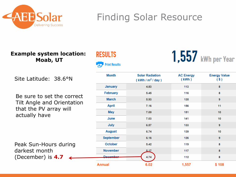
Finding Solar Resource
Example system location: Moab, UT
Peak Sun-Hours during darkest month (December) is 4.7
Site Latitude: 38.6°N
Be sure to set the correct Tilt Angle and Orientation that the PV array will actually have

System Options
• Battery Type: Flooded, AGM or Gel
‒ Considerations: Large system, user on-site
‒ Flooded battery likely to be most cost effective, but AGM may be better for the user
• Battery bank DC voltage : 12, 24, or 48 VDC
‒ Considerations: large system, all loads go through inverter
‒ 48 VDC battery bank likely to be most cost-effective
• Charge controller type: PWM or MPPT
‒ Considerations: Large system, 48 VDC battery bank
‒ MPPT controller only type large enough
‒
• Module Type: 36-cell, 60-cell or 72-cell
‒ Considerations: MPPT charge controller, multi-kW sized array
‒ 60-cell modules likely most cost effective

Battery Bank Sizing
• Daily energy consumption A𝒉 =𝑾𝒉
𝑽𝑫𝑪𝒃𝒂𝒕𝒕𝒆𝒓𝒚 𝒃𝒂𝒏𝒌=
𝟖𝟓𝟒𝟑𝑾𝒉
𝟒𝟖 𝑽𝑫𝑪= 𝟏𝟕𝟖 𝑨𝒉
• 𝑅𝑒𝑞𝑢𝑖𝑟𝑒𝑑 𝐵𝑎𝑡𝑡𝑒𝑟𝑦 𝐵𝑎𝑛𝑘 𝐶𝑎𝑝𝑎𝑐𝑡𝑖𝑡𝑦 =
𝑻𝒐𝒕𝒂𝒍 𝑫𝒂𝒊𝒍𝒚 𝑪𝒐𝒏𝒔𝒖𝒎𝒑𝒕𝒊𝒐𝒏 × (𝑫𝒂𝒚𝒔 𝒐𝒇 𝑨𝒖𝒕𝒐𝒏𝒐𝒎𝒚)
(𝑹𝒆𝒄𝒐𝒎𝒎𝒆𝒏𝒅𝒆𝒅 𝑫𝒆𝒑𝒕𝒉 𝒐𝒇 𝑫𝒊𝒔𝒄𝒉𝒂𝒓𝒈𝒆)× 𝑻𝒆𝒎𝒑𝒎𝒖𝒍𝒕𝒊𝒑𝒍𝒊𝒆𝒓
𝑹𝒆𝒒𝒖𝒊𝒓𝒆𝒅 𝑩𝒂𝒕𝒕𝒆𝒓𝒚 𝑩𝒂𝒏𝒌 𝑪𝒂𝒑𝒂𝒄𝒕𝒊𝒕𝒚 =𝟏𝟕𝟖 × (𝟐)
(𝟓𝟎%)× 𝟏. 𝟎 = 𝟕𝟏𝟐 𝑨𝒉
• What battery to use?
3-string configuration:
𝑴𝒊𝒏𝒊𝒎𝒖𝒎 𝒃𝒂𝒕𝒕𝒆𝒓𝒚 𝒓𝒂𝒕𝒊𝒏𝒈 =𝑹𝒆𝒒𝒖𝒊𝒓𝒆𝒅 𝑪𝒂𝒑𝒂𝒄𝒊𝒕𝒚
𝟑 𝒔𝒕𝒓𝒊𝒏𝒈𝒔=𝟕𝟏𝟐 𝑨𝒉
𝟑= 𝟐𝟑𝟕 𝑨𝒉
2-string configuration:
𝑴𝒊𝒏𝒊𝒎𝒖𝒎 𝒃𝒂𝒕𝒕𝒆𝒓𝒚 𝒓𝒂𝒕𝒊𝒏𝒈 =𝑹𝒆𝒒𝒖𝒊𝒓𝒆𝒅 𝑪𝒂𝒑𝒂𝒄𝒊𝒕𝒚
𝟐 𝒔𝒕𝒓𝒊𝒏𝒈𝒔=𝟕𝟏𝟐 𝑨𝒉
𝟐= 𝟑𝟓𝟔 𝑨𝒉
1-string configuration:
𝑴𝒊𝒏𝒊𝒎𝒖𝒎 𝒃𝒂𝒕𝒕𝒆𝒓𝒚 𝒓𝒂𝒕𝒊𝒏𝒈 =𝑹𝒆𝒒𝒖𝒊𝒓𝒆𝒅 𝑪𝒂𝒑𝒂𝒄𝒊𝒕𝒚
𝟏 𝒔𝒕𝒓𝒊𝒏𝒈𝒔=𝟕𝟏𝟐 𝑨𝒉
𝟏= 𝟕𝟏𝟐 𝑨𝒉

Battery Bank Sizing
Battery Volts Ah #/string Strings QTY Unit $ Total $
IND9-6V 6 VDC 445 8 2 16 $1,250 $20,000
IND13-6V 6 VDC 673 8 1 8 $1,705 $13,640
EnergyCell 800RE
2 VDC 672 24 1 24 NA $14,161
EnergyCell 1100RE
2 VDC 960 24 1 24 NA $18,345
𝑺𝒕𝒓𝒊𝒏𝒈 𝒍𝒆𝒏𝒈𝒕𝒉 =𝑩𝒂𝒕𝒕𝒆𝒓𝒚 𝒃𝒂𝒏𝒌 𝒗𝒐𝒍𝒕𝒂𝒈𝒆
𝑩𝒂𝒕𝒕𝒆𝒓𝒚 𝒖𝒏𝒊𝒕 𝒗𝒐𝒍𝒕𝒂𝒈𝒆

PV Array Sizing
• Loads consume 8543 Wh/day and site receives ~ 4.7 kWh/m2/day in winter
𝑅𝑒𝑞𝑢𝑖𝑟𝑒𝑑 𝐴𝑟𝑟𝑎𝑦 𝑊𝑎𝑡𝑡𝑠 =𝐷𝑎𝑖𝑙𝑦 𝑐𝑜𝑛𝑠𝑢𝑚𝑝𝑡𝑖𝑜𝑛 (𝑊ℎ) × 1.2
𝑘𝑊ℎ 𝑝𝑒𝑟 𝑚2𝑝𝑒𝑟 𝑑𝑎𝑦=8543𝑊ℎ × 1.2
4.7 𝑘𝑊ℎ=10252
4.7= 𝟐𝟏𝟖𝟐𝑊
• Select a PV Module
Considerations: 60-cell, MPPT charge controller, standard roof-mount racking

PV Array Sizing
• Minimum required PV array wattage = 2182 W
• Determine the number of modules required
‒ 𝑀𝑖𝑛𝑖𝑚𝑢𝑚 𝑛𝑢𝑚𝑏𝑒𝑟 𝑜𝑓 𝑚𝑜𝑑𝑢𝑙𝑒𝑠 𝑟𝑒𝑞𝑢𝑖𝑟𝑒𝑑 =𝑃𝑉 𝑎𝑟𝑟𝑎𝑦 𝑠𝑖𝑧𝑒
𝑀𝑜𝑑𝑢𝑙𝑒 𝑁𝑎𝑚𝑒𝑝𝑙𝑎𝑡𝑒=
2182𝑊
255𝑊= 8.6
‒ Most MPPT charge controllers only accept 3 modules per string for a 48 VDC system
3 𝑚𝑜𝑑𝑢𝑙𝑒𝑠 × 4 𝑠𝑡𝑟𝑖𝑛𝑔𝑠 = 9 𝑚𝑜𝑑𝑢𝑙𝑒𝑠
Always round up when determining number of modules!
Recommend oversizing to 12 modules

Charge Controller Selection
• System Requirements
‒ Compatible with sealed AGM batteries, array size is 3,060 W
• Note input voltage limit is 150 VDC
• Maximum charge current for the EnergyCell1100RE is 212 A
• 4 strings of 3 modules each

Inverter Selection
• System requirements
‒ 5,671 W Peak AC Load, All loads 120 VAC/60 Hz, 48 VDC battery bank
‒ Maximum surge load (Washer motor startup): 12 A (1,440 W)
‒ AC generator?
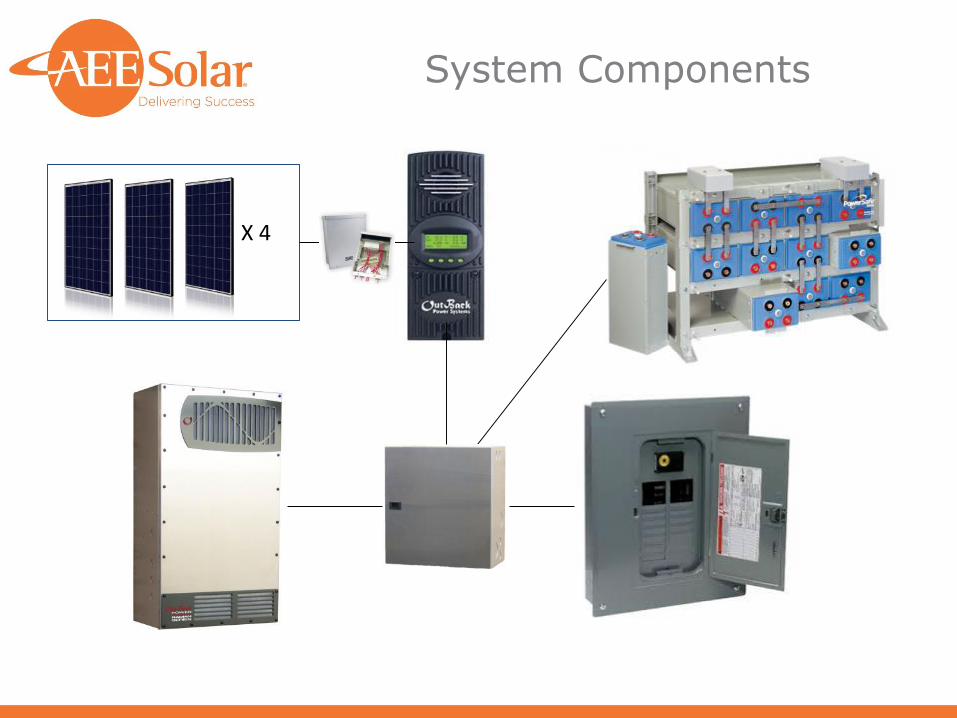
System Components
X 4

Designing a Battery-Based System Step-by-Step
Grid-tie Battery Backup: Backing
up the Grid

Types of Grid-tie Battery Systems
• Backup system separate from the solar grid-tied system
• Grid-tied solar systems with battery backup and protected loads panel
‒ Basic DC coupled grid-tie w/ Battery Backup (GTBB)
‒ GTBB using 120VAC only inverters with 120VAC loads
‒ GTBB using 120VAC only inverters and transformer for 120/240VAC loads
‒ GTBB using 120/240VAC inverters
• Grid-tied solar systems with battery backup for whole house backup
‒ GTBB for whole house using a 4 pole manual transfer switch
‒ GTBB for whole house using line side tap and manual transfer switch
‒ GTBB for whole house using an automatic transfer switch
• Grid-tied solar systems using AC coupling
‒ GTBB using AC coupling and protected loads panel

Direct Grid-tied System without Backup
• This is a simple grid-tie system without any backup power
• When the grid power goes out, the PV system is useless

Backup System Separate from Solar Grid-tied System
• The backup system can be separate from the solar system
• This could also be a generator only or have both inverter and generator

DC-Coupled Grid-Tie w/ Battery Backup (GTBB)
• The original and most common arrangement for grid-tie with backup
• DC coupled with low voltage array, charge controller, and battery-based grid-tie inverter
• Protected loads panel for loads to be backed up
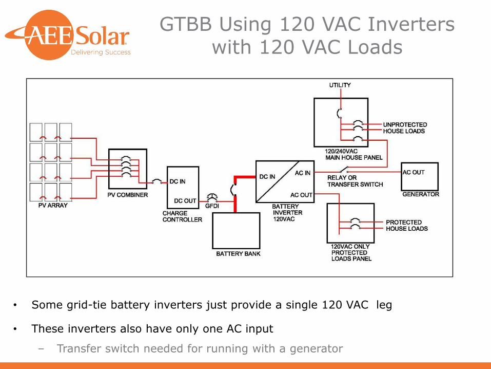
GTBB Using 120 VAC Inverters with 120 VAC Loads
• Some grid-tie battery inverters just provide a single 120 VAC leg
• These inverters also have only one AC input
‒ Transfer switch needed for running with a generator

GTBB Using 120 VAC Inverters with 120/240 VAC Loads
• GTBB 120 VAC system w/protected load panel and transformer for 240 VAC loads
• Use standard US house wiring at 120/240 VAC
• Grid connection and generator input is still only 120 VAC

GTBB Using 120/240 VAC Inverters with Protected Load Panel
• Using a 120/240 VAC split phase inverter with separate generator input is the most versatile and easy to use system
• 120/240 VAC protected loads sub-panel is used
• Grid connection and generator input are both 120/240 VAC

Whole House Backup Issues
• NEC 702 5(B) requires a system that can power all loads if an automatic transfer switch is used,
‒ Exception for loads that are automatically disconnected
‒ A 200A service would require six Radian 8kW inverters
• A Manual transfer switch only requires the system to power chosen loads
‒ User must manually shut off non-critical circuits before switching
‒ Manual transfer will leave the house in the dark until someone does the transfer
• If the inverter cannot power all the loads it will be overloaded and shut off, requiring a manual restart
• The input/grid-feed and output of the inverter must never be connected together
‒ This will irreparably damage the inverter and may cause a fire
‒ Connecting the input to the utility side of the meter is most common approach

Using a Line Tie Connection for a Whole House Backup System
• Line tie connection with fused disconnect and two pole transfer switch
• Transfer switch must be manually activated to meet code
‒ Non-critical circuits must be disconnected first
• Power from the utility must be disconnected to install the transfer switch

Whole House Backup with Automatic Transfer Switch
• Whole house backup with an automatic transfer switch requires a backup system capable of powering all loads, or having loads automatically disconnected NEC 702 5(B)
• 200A service requires six Radian 8kW inverters unless automatic circuit disconnects are used
• Requires a line tie connection to the utility

AC coupled GTBB system
• Normally uses a protected loads panel
• Uses both a direct grid-tie inverter and a battery-based inverter
• Is useful when retrofitting an existing system
• A kWh production meter can still be used
• More expensive and complex, not all equipment is compatible

Battery Based Grid-Tie Inverters

Battery Based Inverters for Grid-tie
• All battery-based inverters must have a battery bank to function
• OutBack FXR and SMA Sunny Island inverters are 120 VAC input and output only
• An autotransformer can be used with a single inverter to produce 120/240 VAC split phase output, or 240 VAC input, but not both with a single transformer
• Two inverters can be stacked to produce 120/240 VAC split phase output
• OutBack Radian and Schneider XW+ inverters are 120/240 VAC split phase input and output
• Up to 10 Radian inverters can be stacked for an 80 kW system
• Up to 4 Schneider XW+ inverters can be stacked for 27.2 kW system
• FXR and Sunny Island inverters have a single AC input
• External transfer switch required for use with a generator
• Radian and XW+ inverters have two AC input circuits
• Compatible with most generators

Battery Based Inverters
• Size inverter for the larger of maximum load or for array size
• During an outage, the inverter must be large enough to run all of the loads that will run at the same time
• The inverter must be large enough to process the full solar array into the grid
• Per 2011 NEC 705.12(D)(2), the grid connection circuit is rated at the maximum inverter grid feed current x 1.25.
• The grid intertie breaker can be larger than the intertie circuit rating so that the intertie breaker can handle the maximum pass-through current
• 50 A or 60 A is a common breaker size for pass-through
• When a single 120 VAC inverter is used, the current for the grid intertie will be double that for a given system size compared to a direct grid-tie inverter running at 240 VAC
• This may be a problem to meet 2008 NEC 690 64(B)(2), or 2011 NEC 705 12(D)(2)

Use Sealed Batteries
• The battery must be large enough to support the backup loads for the time desired
• The battery bank must be large enough to power the inverter adequately
• Also consider: depth of discharge; temperature; inverter efficiency; degradation over lifetime
• The battery bank may be the single largest cost in the system
• Sealed batteries require an enclosure, but not special containment.
• A garage or basement is ideal

Load Analysis: Talk to your Customer
• Protected vs. non-protected loads: what do they really need
• Refrigerator/freezer, lights, ventilation, TV/computer, cell phone charger, alarms
• Heating systems vary widely and may or may not be practical to back up
• Air handlers can be a very large energy load, even if the heat source is gas
• How long do they really need the backup to last?
• Batteries drive the total system cost more than the PV or inverter
• The larger the loads and the longer they run, the more expensive the system will be
• A 100 kWh battery bank (50 kWh/day for 2 days), is likely to cost about $40,000
• Can they add a generator if the backup needs to be larger or last longer?
• Manage the customer’s expectations!
• “A protected loads panel is far more convenient and cost-effective than whole-house backup”
• Accurate load analysis is worth the time and will result in more satisfied customers
• Ensure your customer understands how much energy they can expect from their backup system and the risks of overloading it

Load Analysis
• Sum the protected loads as you would if they were in a separate off-grid system

PV Array Sizing
• Sizing the PV array for GTBB systems is similar to a grid-tie system
• Limits to array size:
• 100% offset of electrical use
• Available space
• Budget
• At minimum the array should power the backup loads for an extended outage
• Sizing for an extended outage needs to account for winter solar production unless the system will also have a generator

Inverter Sizing Considerations
• Inverter must meet the larger of array size or load size
• The inverter needs to be large enough to power all of the loads that will be put on it during a power outage
• A grid-tied inverter also must handle entire PV array power
• This connection does not exist for off-grid systems
• Will any loads require 240 VAC power?
• Same as for off-grid systems
• Wire the protected loads panel for normal North American distribution of 120/240 VAC split phase or just 120 VAC?
• Will the installation use a backup generator?
• will it be 120 VAC only or 240 VAC?

Battery Sizing
• Battery sizing minimum for inverter power
• From OutBack Radian manual:
• “To prevent the inverter’s charger from overcharging, the minimum recommended battery bank size is 350 amp-hours for every Radian inverter/charger installed on the system”
• ”Systems intended to bridge short-term outages can use smaller battery banks. In these cases, the bank can be as low as 200 amp-hours per inverter However, the charge rate must be decreased to half the inverter’s maximum using the MATE3”
• One of the following conditions must also be true:
• “The system is equipped with a backup generator that is programmed for automatic start, or typical grid loss is 30 minutes or less, or the loads are less than 2 kW”
• Other inverters have similar requirements
