pdf manual - shooting star video
TRANSCRIPT

3-868-500-02 (1)
Digital CamcorderOperating InstructionsBefore operating the unit, please read this manual thoroughly and retain it for future reference.
DSR-400L/400PLDSR-400K/400PKDSR-450WSL/450WSPL© 2005 Sony Corporation

2
Owner’s Record
The model and serial numbers are located on the top.Record these numbers in the spaces provided below. Refer to them whenever you call upon your Sony dealer regarding this product.
Model No. Serial No.
To prevent fire or shock hazard, do not expose the unit to rain or moisture.
To avoid electrical shock, do not open the cabinet. Refer servicing to qualified personnel only.
Afin d’éviter tout risque d’incendie ou d’électrocution, ne pas exposer cet appareil à la pluie ou à l’humidité.
Afin d’écarter tout risque d’électrocution, garder le coffret fermé. Ne confier l’entretien de l’appareil qu’à un personnel qualifié.
Um Feuergefahr und die Gefahr eines elektrischen Schlages zu vermeiden, darf das Gerät weder Regen noch Feuchtigkeit ausgesetzt werden.
Um einen elektrischen Schlag zu vermeiden, darf das Gehäuse nicht geöffnet werden. Überlassen Sie Wartungsarbeiten stets nur qualifiziertem Fachpersonal.
WARNING
AVERTISSMENT
WARNUNG
CAUTION
Danger of explosion if battery is incorrectly replaced.
Replace only with the same or equivalent type recommended by the manufacturer.
Dispose of used batteries according to the manufacturer’s instructions.
ADVARSEL!
Lithiumbatteri-Eksplosionsfare ved fejlagtig håndtering.Udskiftning må kun ske med batteri af samme fabrikat og
type.Levér det brugte batteri tilbage til leverandøren.
ADVARSEL
Lithiumbatteri - Eksplosjonsfare.Ved utskifting benyttes kun batteri som anbefalt av
apparatfabrikanten.Brukt batteri returneres apparatleverandøren.
VARNING
Explosionsfara vid felaktigt batteribyte.Använd samma batterityp eller en likvärdig typ som
rekommenderas av apparattillverkaren.Kassera använt batteri enligt gällande föreskrifter.
VAROITUS
Paristo voi räjähtää jos se on virheellisestiasennettu.
Vaihda paristo ainoastaan laitevalmistajansuosittelemaan tyyppiin.
Hävitä käytetty paristo valmistajan ohjeidenmukaisesti.
For customers in the USAThis equipment has been tested and found to comply with the limits for a Class A digital device, pursuant to Part 15 of the FCC Rules. These limits are designed to provide reasonable protection against harmful interference when the equipment is operated in a commercial environment. This equipment generates, uses, and can radiate radio frequency energy and, if not installed and used in accordance with the instruction manual, may cause harmful interference to radio communications. Operation of this equipment in a residential area is likely to cause harmful interference in which case the user will be required to correct the interference at his own expense.
You are cautioned that any changes or modifications not expressly approved in this manual could void your authority to operate this equipment.
The shielded interface cable recommended in this manual must be used with this equipment in order to comply with the limits for a digital device pursuant to Subpart B of Part 15 of FCC Rules.
For the customers in EuropeThis product with the CE marking complies with the EMC Directive (89/336/EEC) issued by the Commission of the European Community.Compliance with this directive implies conformity to thefollowing European standards:• EN55103-1: Electromagnetic Interference (Emission)• EN55103-2: Electromagnetic Susceptibility (Immunity)This product is intended for use in the following Electromagnetic Environment(s):E1 (residential), E2 (commercial and light industrial), E3(urban outdoors) and E4 (controlled EMC environment, ex. TV studio).
Pour les clients européensCe produit portant la marque CE est conforme à la Directive sur la compatibilité électromagnétique (EMC) (89/336/CEE) émise par la Commission de la Communauté européenne.La conformité à cette directive implique la conformité auxnormes européennes suivantes:• EN55103-1: Interférences électromagnétiques
(émission)• EN55103-2: Sensibilité électromagnétique (immunité)Ce produit est prévu pour être utilisé dans les environnements électromagnétiques suivants:E1 (résidentiel), E2 (commercial et industrie légère),E3 (urbain extérieur) et E4 (environnement EMC contrôlé,ex. studio de télévision).
Für Kunden in EuropaDieses Produkt besitzt die CE-Kennzeichnung Und erfüllt die EMV-Richtlinie (89/336/EWG) der EG-Kommission.Angewandte Normen:• EN55103-1: Elektromagnetische Verträglichkeit
(Störaussendung)• EN55103-2: Elektromagnetische Verträglichkeit
(Störfestigkeit),für die folgenden elektromagnetischen Umgebungen: E1 (Wohnbereich), E2 (kommerzieller und in beschränktem Maße industrieller Bereich), E3 (Stadtbereich im Freien) und E4 (kontrollierter EMV-Bereich, z.B. Fernsehstudio).
For the customers in Taiwan only
Voor de Klanten in NederlandGooi de batterij niet weg maar lever deze in
als klein chemisch afval (KCA).
Für Kunden in DeutschlandEntsorgungshinweis: Bitte werfen Sie nur entladene Batterien in die Sammelboxen beim Handel oder den Kommunen. Entladen sind Batterien in der Regel dann, wenn das Gerät abschaltet und signalisiert “Batterie leer” oder nach längerer Gebrauchsdauer der Batterien “nicht mehr einwandfrei funktioniert”. Um sicherzugehen, kleben Sie die Batteriepole z.B. mit einem Klebestreifen ab oder geben Sie die Batterien einzeln in einen Plastikbeutel.
Note about laser beamsLaser beams can damage the CCDs of this camcorder. In environments where laser beams are used, be careful to prevent the laser beams from striking the surfaces of the CCDs.
3

4
Table of Contents
Chapter 1 Overview
Product Configurations .............................6Features ......................................................7
Camera features ............................................7VTR features.................................................8
Location and Function of Parts ................9Front view.....................................................9Right side view ...........................................10Left and upper view....................................15Rear view....................................................17Lens.............................................................19DXF-801 Viewfinder..................................20Status display on the viewfinder screen......21Status display on the LCD monitor ............23
Using the CD-ROM Manual...................... 25CD-ROM system requirements ..................25Preparations ................................................25Reading the CD-ROM manual ...................25
Chapter 2 Preparation
Attaching and Replacing the Lithium Battery ................................................ 27
Preparing the Lens................................... 28Mounting the lens .......................................28Adjusting the flange focal length................28
Preparing a Power Supply....................... 29Using a battery pack ...................................29Using an AC adaptor ..................................29Avoiding breaks in operation due to an
exhausted battery...............................30Adjusting the Viewfinder ......................... 30
Adjusting the viewfinder position ..............30Adjusting the eyepiece focus and the screen
(brightness, contrast, and outline emphasis)...........................................30
Removing the viewfinder ...........................31Attaching a 5-inch electronic viewfinder ...31
Using the Shoulder Strap ........................ 32Adjusting the Shoulder Pad Position ..... 32Fitting to a Tripod..................................... 33
Using a Video Light.................................. 33Preparing Audio Input System................ 34
Using the supplied microphone ................. 34Using an external microphone ................... 34Using a wireless microphone system......... 35Connecting line input audio equipment ..... 37
Connecting the Remote Control Unit (DSR-450WS/450WSP only) .............. 37
Chapter 3 Connections
Connecting a Monitor .............................. 40Using an i.LINK Connection.................... 41
Settings required for an i.LINK connection ........................................ 41
Making a backup of the images being recorded............................................ 41
Using the camcorder as a feeder ................ 42Other Connections................................... 44
Connecting a number of camcorders ......... 44
Chapter 4 Recording and Playback
Inserting a Cassette ................................. 45Basic Procedure for Shooting ................ 46Recording ................................................. 47
Usable cassettes ......................................... 47Selecting the recording format................... 49Adjusting the black balance/white
balance.............................................. 50Setting the electronic shutter ..................... 52Adjusting the iris........................................ 55Adjusting the audio level ........................... 57Setting the time data .................................. 57Setting for special shooting cases .............. 60
Back Space Editing.................................. 61Starting back space editing at any tape
position ............................................. 61Using the edit search function while back
space editing..................................... 62Time-Lapse Video (Interval Rec)............. 63
Making settings before shooting................ 63Shooting and recording in Interval Rec
mode ................................................. 63
Recording Analog Composite Signals (with a CBK-SC01 Installed- DSR-450WS/450WSP only) ............... 64
Playing and Checking Recorded Contents ............................................. 65Checking the recorded contents immediately
after shooting — Recording Review..65Checking the recording on the color video
monitor ..............................................65
Chapter 5 Menu Displays and Detailed Settings
Menu Organization and Operation.......... 66The TOP menu............................................73Menu list .....................................................75Displaying menus .......................................93Basic menu operations................................93Using the USER menu (Example of the
menu operation).................................94Editing the USER menu..............................95Resetting USER menu settings to the
standard settings ................................98Setting the Status Display on the
Viewfinder Screen and the LCD Monitor ............................................... 98Selecting the display items .........................98Display modes and setting change
confirmation/adjustment progress messages............................................99
Setting the marker display ........................100Setting the viewfinder...............................100Recording shot data superimposed on the
color bars .........................................101Setting the shot ID ....................................101Displaying the status confirmation
windows ..........................................102Adjustments and Settings from
Menus ...............................................103Setting gain values for the GAIN switch
positions ..........................................103Selecting the output signals
(DSR-450WS/450WSP only)..........104Setting the color temperature manually....104Specifying an offset for the auto white
balance setting .................................105
Setting the date/time of the internal clock ............................................... 105
Assigning functions to ASSIGN switches .......................................... 106
Selecting the lens file............................... 106Selecting the aspect ratio
(DSR-450WS/450WSP only)......... 107Setting the CCD scan mode
(DSR-450WS/450WSP only)......... 108
Chapter 6 Saving and Loading the User Setting Data
Saving and Loading User Files............. 109Handling the “Memory Stick” ................. 109Saving USER menu data (user file) to
the “Memory Stick” ....................... 110Loading saved data from
a “Memory Stick”........................... 112Saving and Loading Scene Files .......... 113
Saving a scene file ................................... 113Loading scene files .................................. 115Resetting the settings of the camcorder
to the standard settings ................... 116Displaying a File-Related Menu Page
When Inserting a “Memory Stick” .. 117
Chapter 7 Appendix
Important Notes on Operation .............. 118Characteristics of CCD sensors ............... 119
Maintenance ........................................... 120Cleaning the video heads ......................... 120Replacing the video heads ....................... 120Replacing other parts ............................... 120Using the auto-check function ................. 120
About i.LINK ........................................... 122About a “Memory Stick”........................ 123Operation Warnings............................... 125Troubleshooting..................................... 128Specifications......................................... 130Chart of Optional Components and
Accessories ..................................... 133Glossary.................................................. 135Index........................................................ 137
5
hapter
6
Chapter 1 O
verview
COverview
Product Configurations
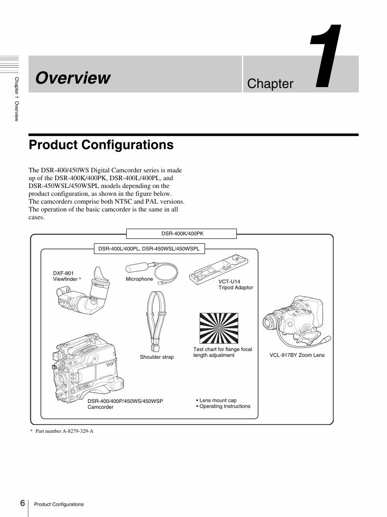
The DSR-400/450WS Digital Camcorder series is made up of the DSR-400K/400PK, DSR-400L/400PL, and DSR-450WSL/450WSPL models depending on the product configuration, as shown in the figure below.The camcorders comprise both NTSC and PAL versions.The operation of the basic camcorder is the same in all cases.
DSR-400K/400PK
DSR-400L/400PL, DSR-450WSL/450WSPL
DXF-801 Viewfinder *
DSR-400/400P/450WS/450WSP Camcorder
Shoulder strap VCL-917BY Zoom LensTest chart for flange focal length adjustment
Microphone VCT-U14 Tripod Adaptor
• Lens mount cap• Operating Instructions
* Part number A-8279-329-A
Product Configurations
Chapter 1 O
verview
Features
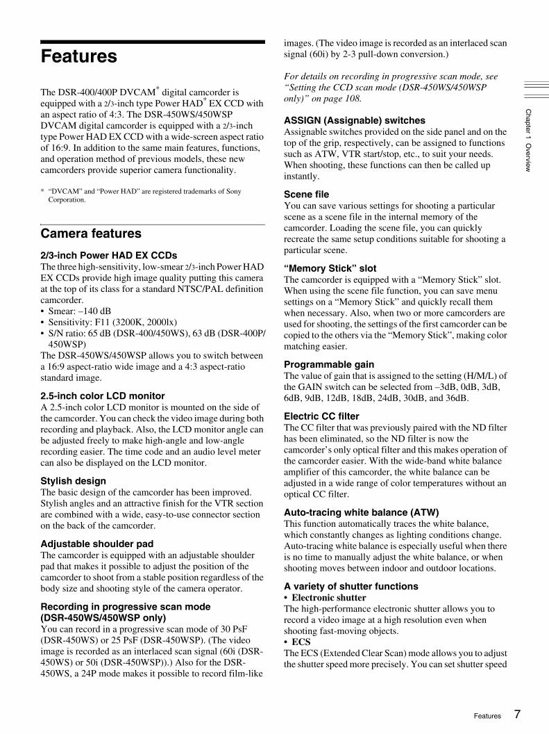
The DSR-400/400P DVCAM* digital camcorder is equipped with a 2/3-inch type Power HAD* EX CCD with an aspect ratio of 4:3. The DSR-450WS/450WSP DVCAM digital camcorder is equipped with a 2/3-inch type Power HAD EX CCD with a wide-screen aspect ratio of 16:9. In addition to the same main features, functions, and operation method of previous models, these new camcorders provide superior camera functionality.
* “DVCAM” and “Power HAD” are registered trademarks of Sony Corporation.
Camera features
2/3-inch Power HAD EX CCDsThe three high-sensitivity, low-smear 2/3-inch Power HAD EX CCDs provide high image quality putting this camera at the top of its class for a standard NTSC/PAL definition camcorder.• Smear: –140 dB• Sensitivity: F11 (3200K, 2000lx)• S/N ratio: 65 dB (DSR-400/450WS), 63 dB (DSR-400P/
450WSP)The DSR-450WS/450WSP allows you to switch between a 16:9 aspect-ratio wide image and a 4:3 aspect-ratio standard image.
2.5-inch color LCD monitorA 2.5-inch color LCD monitor is mounted on the side of the camcorder. You can check the video image during both recording and playback. Also, the LCD monitor angle can be adjusted freely to make high-angle and low-angle recording easier. The time code and an audio level meter can also be displayed on the LCD monitor.
Stylish designThe basic design of the camcorder has been improved. Stylish angles and an attractive finish for the VTR section are combined with a wide, easy-to-use connector section on the back of the camcorder.
Adjustable shoulder padThe camcorder is equipped with an adjustable shoulder pad that makes it possible to adjust the position of the camcorder to shoot from a stable position regardless of the body size and shooting style of the camera operator.
Recording in progressive scan mode (DSR-450WS/450WSP only)You can record in a progressive scan mode of 30 PsF (DSR-450WS) or 25 PsF (DSR-450WSP). (The video image is recorded as an interlaced scan signal (60i (DSR-450WS) or 50i (DSR-450WSP)).) Also for the DSR-450WS, a 24P mode makes it possible to record film-like
images. (The video image is recorded as an interlaced scan signal (60i) by 2-3 pull-down conversion.)
For details on recording in progressive scan mode, see “Setting the CCD scan mode (DSR-450WS/450WSP only)” on page 108.
ASSIGN (Assignable) switchesAssignable switches provided on the side panel and on the top of the grip, respectively, can be assigned to functions such as ATW, VTR start/stop, etc., to suit your needs. When shooting, these functions can then be called up instantly.
Scene fileYou can save various settings for shooting a particular scene as a scene file in the internal memory of the camcorder. Loading the scene file, you can quickly recreate the same setup conditions suitable for shooting a particular scene.
“Memory Stick” slotThe camcorder is equipped with a “Memory Stick” slot. When using the scene file function, you can save menu settings on a “Memory Stick” and quickly recall them when necessary. Also, when two or more camcorders are used for shooting, the settings of the first camcorder can be copied to the others via the “Memory Stick”, making color matching easier.
Programmable gainThe value of gain that is assigned to the setting (H/M/L) of the GAIN switch can be selected from –3dB, 0dB, 3dB, 6dB, 9dB, 12dB, 18dB, 24dB, 30dB, and 36dB.
Electric CC filterThe CC filter that was previously paired with the ND filter has been eliminated, so the ND filter is now the camcorder’s only optical filter and this makes operation of the camcorder easier. With the wide-band white balance amplifier of this camcorder, the white balance can be adjusted in a wide range of color temperatures without an optical CC filter.
Auto-tracing white balance (ATW)This function automatically traces the white balance, which constantly changes as lighting conditions change. Auto-tracing white balance is especially useful when there is no time to manually adjust the white balance, or when shooting moves between indoor and outdoor locations.
A variety of shutter functions• Electronic shutterThe high-performance electronic shutter allows you to record a video image at a high resolution even when shooting fast-moving objects.• ECS The ECS (Extended Clear Scan) mode allows you to adjust the shutter speed more precisely. You can set shutter speed
7Features

8
Chapter 1 O
verview
to a value close to the scan frequency of a computer display, so that the horizontal band and flicker that appear when recording a computer display can be reduced. • Slow shutter (DSR-450WS/450WSP only)A slow shutter function allows you to set the exposure time longer than 1 frame. By doing so, sensitivity is improved dramatically. Also, dreamlike images using the afterimages can be shot.
Setting of multiple gamma curves (DSR-450WS/450WSP only)Setting of multiple gamma curves is possible using a menu. You can shoot using image tones that suit your purpose, such as making film-like images.
Dual zebra pattern displayTwo types of zebra patterns can be set at independent display levels. They can be used in various ways; for example, one can be set to the brightness level of the main objects, and the other can be set to a higher brightness level.
Video light connectorA video light connector (maximum 50 W) and control switch are provided. You can set the switch to turn the light on and off automatically as you start and stop the VTR.
Remote control connectors (DSR-450WS/450WSP only)Instead of making settings using menus, detailed settings of the camcorder can be made using an optional RM-B150 or B750 remote control unit connected to the camcorder.
High-capacity BP-GL95 Battery PackThe camcorder supports the information battery function. When using a BP-GL65/GL95 Battery Pack, more accurate and detailed information on remaining battery power is displayed in the viewfinder.
High-functionality DXF-801 ViewfinderThe supplied DXF-801 Viewfinder has the following features.• High resolution (600 TV lines of horizontal resolution)• A DISPLAY switch that can turn the character display
on and off• A light for the lens control elements• A large-diameter eye cup with a flip-up mechanism for
viewing with the eye apart from it• A peaking potentiometer for vertical and horizontal
detail control• A tough, die-cast aluminium body• Automatic aspect ratio switching between 16:9 and 4:3
(DSR-450WS/450WSP only)
VTR features
Standard-size and mini-size DVCAM cassettesEquipped with a tape drive with an original Sony mechanism, this camcorder can use both standard-size DVCAM cassettes (a standard cassette that can record a maximum of 180 minutes in DVCAM mode) and mini-size DVCAM cassettes (a small cassette that is convenient to carry and store). Both can be used without an adaptor.
Compatible with DV recording (SP mode)In addition to recording in DVCAM mode, this camcorder can record in the same DV mode that is widely available in consumer-use camcorders. (Only recording in SP mode is available. LP mode is not available for either recording or playback.) Recording in DV format allows a longer recording time, 270 minutes for a DVCAM 180-minute tape. This helps to reduce tape-changing time and the risk of missing important scenes when shooting a long event.
PCM digital audioFor tapes recorded in DVCAM mode, recording/playback can be set to audio lock mode. You can choose between the two-channel recording mode (with a sampling frequency of 48 kHz) or the four-channel recording mode (with a sampling frequency of 32 kHz, records only CH-1 and CH-2 on this camcorder).
(i.LINK) DV OUT connector*
This camcorder has an (i.LINK) DV OUT connector. You can connect other DVCAM/DV recorders or i.LINK (DV) compatible non-linear editing equipment supporting a digital signal interface without degradation. Connecting external VTR equipment allows you to back up recordings to avoid missing any scenes by mistake. Also, you can set the REC TRIGGER switch to suit your needs and you can control the VTR sections of the camcorder and any external equipment independently.
* “i.LINK” and are trademarks.
VBS video input signal (DSR-450WS/450WSP only)By installing an optional CBK-SC01 Composite Input Board, the camcorder can input and record an external analog video signal. This is useful for pool coverage, etc.
Interval Rec functionUsing the Interval Rec function, you can create time-lapse videos. This is useful for various specialized projects, such as time-lapse recording of plant growth, etc.
Features

Chapter 1 O
verview
Location and Function of Parts
Front view
a Lens mount capRemove by pushing up the lens locking lever (page 10). When no lens is mounted, keep this cap fitted for protection from dust.
b LENS connector (12-pin)Connect the lens cable. Contact your Sony representative for more information about the lens you can use.
c REC (recording start) buttonPress to start recording. Press it again to stop recording. The effect is exactly the same as that of the VTR button on the lens. When the REC SWITCH function is assigned to the ASSIGN switch on the FUNCTION 1 page of the OPERATION menu, you can use the switch as the REC button.
You can select the recording format for the video signal from either DVCAM mode or DV-SP mode on the VTR MODE page of the MAINTENANCE menu.
In the recording pause state, the camcorder waits for a certain period of time in the standby-on mode and then automatically switches to standby-off mode. This length of the standby-on period with no operation can be set to either 1 minute, 3 minutes, or 5 minutes on the VTR MODE page of the MAINTENANCE menu.
d AUTO W/B BAL (automatic white/black balance adjustment) switch
Activates the white/black balance automatic adjustment functions.WHT: Adjusts the white balance automatically. If the
WHITE BAL switch (page 11) is set to A or B, the white balance setting is stored in the corresponding memory.
BLK: Adjusts the black set and black balance automatically.
e VF (viewfinder) connector (20-pin)Connect the supplied DXF-801 Viewfinder.
f Lens mount (special bayonet mount)Attach the lens.
g FILTER selectorSelects the most appropriate filter to match the light source illuminating the subject. When this selector is used with the display mode set to 3 (page 99), the new setting appears on the viewfinder screen for about 3 seconds.
FILTER selector setting and examples of shooting conditions
3 REC button
1 Lens mount cap
4 AUTO W/B BAL switch
6 Lens mount
7 FILTER selector
2 LENS connector
5 VF connector
8 ZEBRA button
9 ASSIGN 1/2 switches
0 Lens locking lever
qa MENU knob
qs SHUTTER switch
qd AUDIO LEVEL knob
FILTER selector setting Examples of shooting conditions
1 (CLEAR) Studio halogen lighting (incandescent)
2 (1/4 ND) Cloudy or rainy outdoor shooting, or to reduce the depth of field*
3 (1/16 ND) Sunlight
4 (1/64 ND) To reduce the depth of field in sunlight
9Location and Function of Parts

10
Chapter 1 O
verview
* The range over which the subject is sharply in focus. Thus, “reducing the depth of field” means that the range is reduced as well, and “increasing the depth of field” means that it is increasing as well.
h ZEBRA buttonPress to display a zebra pattern (diagonal stripes) in the viewfinder screen. The zebra pattern is factory set to indicate picture areas where the video level is approximately 70%. However, on the VF SETTING page of the OPERATION menu, you can change the setting so that areas where the video level is 100% and above also displayed at the same time.
For details, see “Setting the viewfinder” on page 100.
i ASSIGN 1/2 switchesYou can assign the desired functions on the FUNCTION 1 page of the OPERATION menu.
For details, see “Assigning functions to ASSIGN switches” on page 106.
j Lens locking leverAfter inserting the lens in the lens mount, rotate the lens mount ring with this lever to lock the lens in position.
k MENU knobChanges the page selection or a setting within the menu.
For details about how to use the MENU knob, see “Basic menu operations” on page 93.
l SHUTTER switchSet to ON to use the electronic shutter. Flick to SEL to switch the shutter speed or shutter mode setting within the range previously set with the menu. When this switch is operated, the new setting appears on the setting change/adjustment progress message display area for about 3 seconds.
For details about the shutter speed and shutter mode settings, see “Setting the electronic shutter” on page 52.
m AUDIO LEVEL knobAdjusts the channel 1 audio input level manually. You can invalidate the setting of this knob in the F AUDIO VOL item on the AUDIO page of the MAINTENANCE menu.
Right side view
Front section
a 5600K buttonPress to lit the button and switch the standard color temperature for shooting to 5600K. Use this button for outdoor shooting in daytime or shooting under lighting with higher temperature. While setting the wide-band white balance, the button does not function.
b LIGHT switchDetermines how a video light connected to the LIGHT connector (page 16) is turned on and off.AUTO: When the POWER switch of the video light is in
the on position, the video light is turned on automatically while the camcorder is recording. When using the interval recording mode, the video light is automatically turned on immediately before recording starts.
MAN: You can turn the video light on or off manually, using its own switch.
3 OUTPUT/DCC switch
1 5600K button
4 GAIN switch
6 MONITOR knob
7 ALARM knob2 LIGHT switch
5 POWER switch
8 LCD monitor
9 MENU switch
0 WHITE BAL switch
Location and Function of Parts
Chapter 1 O
verview
To ensure proper operation of the video light, Sony recommends the use of the battery pack BP-GL65, BP-GL95, or BP-L60S with the camcorder.
c OUTPUT /DCC (output signal/dynamic contrast control) switch
Switches the video signal, which is output to the VTR part, viewfinder, and video monitor from the camera part, between the following two.BARS: Outputs the color bar signal.CAM: Outputs the video signal from the camera. When this is selected, you can switch DCC* on and off.
* DCC (Dynamic Contrast Control): Against a very bright background with the iris opening adjusted to the subject, objects in the background will be lost in the glare. The DCC function will suppress the high intensity and restore much of the lost detail and is particularly effective in the following cases.• Shooting people in the shade on a sunny day• Shooting a subject indoors, against a background through a window• Any high contrast scene
d GAIN switchSwitches the gain of the video amplifier to match the lighting conditions during shooting. The gains corresponding to the L, M, and H settings can be selected in the menu. (The factory settings are L = 0 dB, M = 9 dB, and H = 18 dB.)When this switch is adjusted, the new setting appears on the setting change/adjustment progress message display area of the viewfinder screen for about 3 seconds.
For details, see “Setting gain values for the GAIN switch positions” on page 103.
e POWER switchTurns the main power supply on and off.
f MONITOR (monitor volume adjustment) knobControls the volume of the sound other than the warning tone that is output via the built-in speaker or earphones. Turning this knob to the minimum setting mutes the audio output.
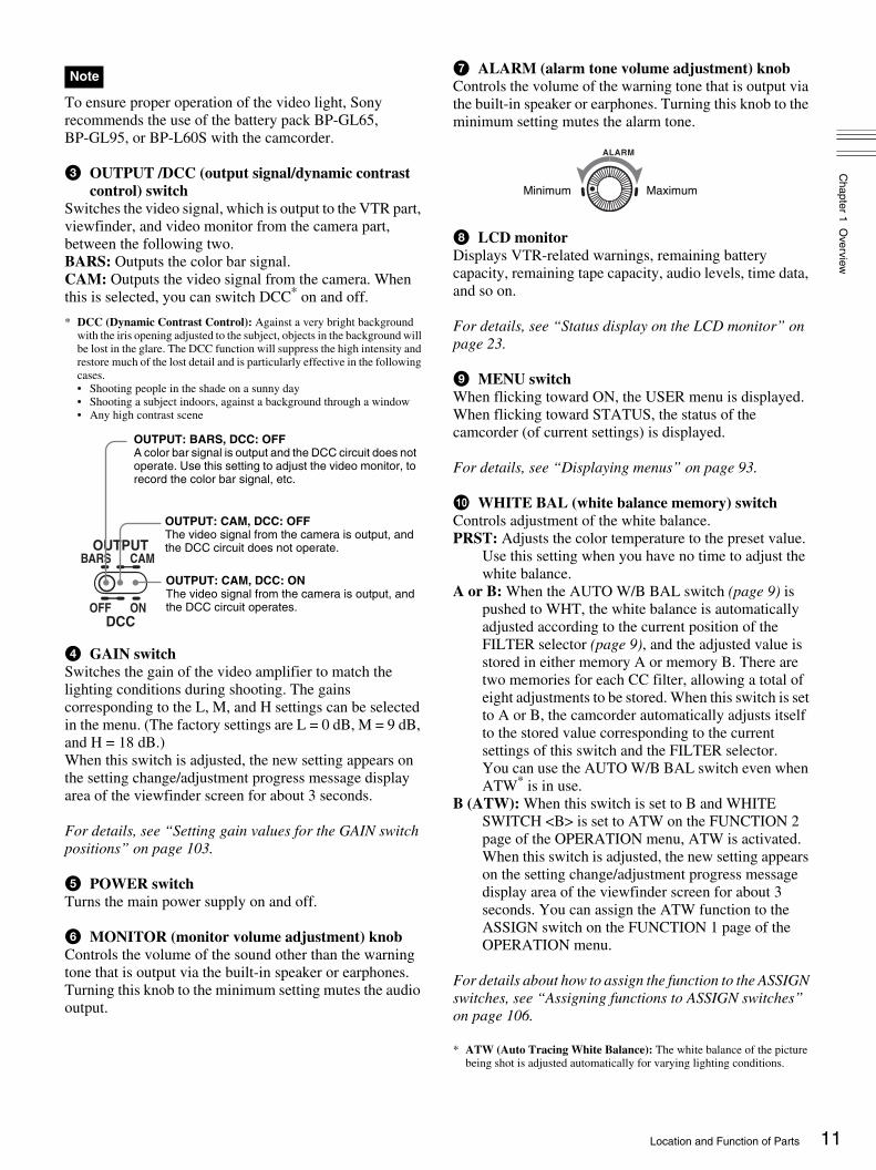
g ALARM (alarm tone volume adjustment) knobControls the volume of the warning tone that is output via the built-in speaker or earphones. Turning this knob to the minimum setting mutes the alarm tone.
h LCD monitorDisplays VTR-related warnings, remaining battery capacity, remaining tape capacity, audio levels, time data, and so on.
For details, see “Status display on the LCD monitor” on page 23.
i MENU switchWhen flicking toward ON, the USER menu is displayed. When flicking toward STATUS, the status of the camcorder (of current settings) is displayed.
For details, see “Displaying menus” on page 93.
j WHITE BAL (white balance memory) switchControls adjustment of the white balance.PRST: Adjusts the color temperature to the preset value.
Use this setting when you have no time to adjust the white balance.
A or B: When the AUTO W/B BAL switch (page 9) is pushed to WHT, the white balance is automatically adjusted according to the current position of the FILTER selector (page 9), and the adjusted value is stored in either memory A or memory B. There are two memories for each CC filter, allowing a total of eight adjustments to be stored. When this switch is set to A or B, the camcorder automatically adjusts itself to the stored value corresponding to the current settings of this switch and the FILTER selector. You can use the AUTO W/B BAL switch even when ATW* is in use.
B (ATW): When this switch is set to B and WHITE SWITCH <B> is set to ATW on the FUNCTION 2 page of the OPERATION menu, ATW is activated. When this switch is adjusted, the new setting appears on the setting change/adjustment progress message display area of the viewfinder screen for about 3 seconds. You can assign the ATW function to the ASSIGN switch on the FUNCTION 1 page of the OPERATION menu.
For details about how to assign the function to the ASSIGN switches, see “Assigning functions to ASSIGN switches” on page 106.
* ATW (Auto Tracing White Balance): The white balance of the picture being shot is adjusted automatically for varying lighting conditions.
Note
OUTPUT
DCC
CAMBARS
ONOFF
OUTPUT: BARS, DCC: OFFA color bar signal is output and the DCC circuit does not operate. Use this setting to adjust the video monitor, to record the color bar signal, etc.
OUTPUT: CAM, DCC: OFFThe video signal from the camera is output, and the DCC circuit does not operate.
OUTPUT: CAM, DCC: ONThe video signal from the camera is output, and the DCC circuit operates.
ALARM
Minimum Maximum
11Location and Function of Parts

12
Chapter 1 O
verview
Left side of the LCD monitor
a LCD buttonControls the LCD monitor. Each time pressing this button, the setting changes as follows.L: The LCD monitor is adjusted for viewing indoors.H: The LCD monitor is adjusted for viewing outdoors.OFF: The LCD monitor is turned off.
b RESET (counter reset) buttonResets the display of the time data when the LCD monitor display is set to STATUS with the DISP SEL button. According to the settings of the PRESET/REGEN/CLOCK switch (page 14) and the F-RUN/SET/R-RUN switch (page 14), resets the display as follows.
* One of the time code bits recorded on a tape can be used to record the necessary information for the user.
For details, see “Setting the time data” on page 57.
c DISPLAY (counter display toggle) buttonEach time this button is pressed, the counter display section changes as follows. This setting is activated only when the LCD monitor display is set to STATUS with the DISP SEL button.COUNTER: Displays the elapsed recording/playback
time.TC: Displays time code.U-BIT: Displays user bit data.
d DISP SEL (display selection) buttonEach time pressing this button, the display in the LCD monitor changes as follows.CHAR: Displays video with superimposed text. With the
MENU switch set to STATUS, also display camcorder status indications similar to those displayed in the viewfinder.
MONI: Displays video without superimposed text.STATUS: Displays counter, warnings, audio levels, etc.
1 LCD button
2 RESET button
3 DISPLAY button
4 DISP SEL button
Settings of the button and the switch
To reset
DISPLAY button: COUNTER Counter to 0:00:00
DISPLAY button: TCPRESET/REGEN/CLOCK switch: PRESETF-RUN/SET/R-RUN switch: SET
Time code to 00:00:00:00
DISPLAY button: U-BITPRESET/REGEN/CLOCK switch: PRESETF-RUN/SET/R-RUN switch: SET
User bit data* to 00 00 00 00
Location and Function of Parts

Chapter 1 O
verview
Rear section
a PLAY button and indicatorPress to view a playback image using the viewfinder or a LCD monitor. The indicator lights during playback.Pressing this button again during playback pauses the playback, showing a still image. At this time, the indicator flashes. This camcorder is capable of color-image search at approximately nine-times (NTSC system) or eleven-times (PAL system) normal playback speed, making it easy to check recorded material. To use the color-image search, press and hold the REW or F FWD button during playback. While the button is pressed, the PLAY indicator and the REW or F FWD indicator light.
b REW button and indicatorRewinds the tape. The indicator lights while the tape is being rewound.
c EDIT SEARCH +FWD/–REV buttonsPress these buttons in recording pause mode or in stop mode to find the next recording start point quickly. You can search in playback while pressing either of these buttons, or you can search by frame when pressing the button and releasing it immediately. If you do not operate the camcorder for about three seconds after releasing the buttons, the camcorder will enter the REC standby mode at the point where the buttons were released.
d F FWD button and indicatorFast forwards the tape. The indicator lights while the tape is being fast forwarded.
e STOP buttonStops playing, rewinding, or fast forwarding the tape.
f WARNING indicatorLights up or blinks when an abnormality occurs in the VTR section.
For details about the meaning of the lights displayed, see “Operation Warnings” on page 125.
g TAPE indicatorLights up as below depending on the situation.Continuous: When the cassette is in the camcorder.Blinking: While the cassette is loading or ejecting.Lights-out: When the cassette is not in the camcorder.
h Built-in speakerThe speaker can be used to monitor E-E* sound during recording, and playback sound during playback. The speaker also sounds alarms to reinforce visual warnings. If you connect earphones to the EARPHONE jack, the speaker is automatically muted.
* E-E: Abbreviation of “Electric-to-Electric.” In E-E mode, video and audio signals input to the camcorder are output after passing through internal electric circuits only. This can be used to check input signals.
For information about alarms, see “Operation Warnings” on page 125.
i AUDIO adjustment coverOpen to reveal the audio setting switches (page 14) and make audio adjustments.
j EARPHONE jack (monaural)Plugging earphones, and you can monitor the E-E sound during recording and playback sound during playback. When an alarm is indicated, you can hear the alarm sound through the earphones. Plugging earphones into the jack automatically cuts off the sound from built-in speaker.
EDIT STOPREV
REW PLAY F FWD
FWDSEARCH3 EDIT SEARCH
+FWD/–REV buttons
1 PLAY button and indicator
4 F FWD button and indicator
6 WARNING indicator
7 TAPE indicator
2 REW button and indicator
5 STOP button
8 Built-in speaker
9 AUDIO adjustment cover
0 EARPHONE jack
13Location and Function of Parts

14
Chapter 1 O
verview
Operation panel under the AUDIO adjustment cover
a MONITOR OUT (monitor output) CHARACTER switch
Selects to superimpose text information on the monitor output.
b MONITOR SELECT (audio monitor selection) switch
Selects audio output via the built-in speaker or earphones.CH-1: Channel 1 audioMIX: Mixed audio (channels 1 and 2)CH-2: Channel 2 audio
c PRESET/REGEN (regeneration)/CLOCK switchSelects whether to set a new time code or to utilize the existing time code. PRESET: Records a new time code.REGEN: Records time code continuous with the existing
time code recorded on the tape. Regardless of the setting of the F-RUN/SET/R-RUN switch, the camcorder operates in R-RUN mode.
CLOCK: Records time code synchronized to the internal clock. Regardless of the setting of the F-RUN/SET/R-RUN switch, the camcorder operates in F-RUN mode.
d Lithium battery compartmentAttach the supplied CR2032 Lithium Battery.
Details on how to attach the lithium battery, see “Attaching and Replacing the Lithium Battery” on page 27.
e Arrow keySets the time code and the user bit. Push the key towards left or right so that the digit you want to change flashes. Pushing the key upward increases the value of the flashing digit, and pushing it downward decreases the value.
f AUDIO LEVEL (CH-1/CH-2) (audio channel 1/2 recording level) controls
If the audio is input via the AUDIO IN CH-1/CH-2 connectors, adjusts the audio levels of channels 1 and 2
when the AUDIO SELECT (CH-1/CH-2) switches (see below) are set to MANUAL.
g F-RUN/SET/R-RUN (free run/set/recording run) switch
Selects the operating mode for the internal time code generator. The operating mode is set as explained below, depending on the position of the switch.F-RUN: Time code keeps advancing, regardless of the
operating state of the VTR. Use this setting when synchronizing the time code with an external time code.
SET: Sets the time code or user bits.R-RUN: The time code value advances only during
recording. Use this setting to have a consecutive time code on the tape.
For details, see “To set the time code” on page 57 and “To set the user bits” on page 58.
h AUDIO SELECT (CH-1/CH-2) (audio channel 1/2 adjustment method selection) switches
Select the audio level adjustment method for each of audio channels 1 and 2.AUTO: Automatic adjustmentMANUAL: Manual adjustment
CH-1
CH-2
MONITORSELECT
MIX
PRESET
CLOCK
FRONT MICLOW OUT
REGENF-RUN
R-RUN
RECTRIGGER
SET
ONOFF
AUTOMANUAL
PARALLEL
EXT ONLYINT ONLY
FRONT
CH-1 CH-1AUDIO IN
AUDIO LEVEL
REARWRR
ONOFF
MONITOR OUTCHARACTER
LITHIUM BATTAUDIO SELECT
1 MONITOR OUT CHARACTER switch
2 MONITOR SELECT switch
3 PRESET/REGEN/CLOCK switch
4 Lithium battery compartment
5 Arrow key
6 AUDIO LEVEL controls
9 AUDIO IN switches
7 F-RUN/SET/R-RUN switch
8 AUDIO SELECT switches
0 REC TRIGGER switchqa FRONT MIC LOW CUT switch
Location and Function of Parts

Chapter 1 O
verview
i AUDIO IN (CH-1/CH-2) (audio channel 1/2 input selection) switches
Select the audio input signals to be recorded on audio channels 1 and 2. The audio input is sourced as explained below based on the position of the switches.FRONT: The microphone connected to the MIC IN (+48
V) connector (page 16)WRR: A WRR-855 UHF Synthesized Tuner Unit (not
supplied)REAR: Audio equipment connected to the AUDIO IN
CH-1/CH-2 connectors (page 18)
The following settings can be made on the AUDIO page of the MAINTENANCE menu.• Audio recording format
Select either Fs48K or 32K.• Audio reference level
Select either –12 dB or –20 dB (DSR-400/450WS), –12 dB or –18 dB (DSR-400P/450WSP).
• Audio fade-in/fade-out Select either ON or OFF.
j REC TRIGGER (external VTR trigger) switchSets the function of the REC button on the camcorder or the VTR button on the lens when an external VTR is connected to the (i.LINK) DV OUT connector (page 18). Set this switch to INT ONLY when you need to do cut editing or dubbing using the (i.LINK) DV OUT connector.PARALLEL: Operates both internal and external VTRs
simultaneously.INT ONLY: Operates the internal VTR only. External
VTR operation is performed locally.EXT ONLY: Operates the external VTR only.
k FRONT MIC LOW CUT switchSet to ON to insert a high-pass filter in the microphone circuit, reducing wind noise. Normally leave the switch in the OFF position.
Left and upper view
Front section
a Accessory shoeAttach an optional accessory such as a video light (page 33).
b ASSIGN 3/4 switchesYou can assign the desired functions on the FUNCTION 1 page of the OPERATION menu.
For details, see “Assigning functions to ASSIGN switches” on page 106.
c Viewfinder front-to-back position locking knobLoosen this knob to adjust the front-to-back position of the viewfinder (page 30).
d Shoulder strap fittingAttach the supplied shoulder strap (page 32).
e Viewfinder left-to-right positioning ringLoosen this ring to adjust the left-to-right position of the viewfinder (page 30).
1 Accessory shoe
2 ASSIGN 3/4 switches
3 Viewfinder front-to-back position locking knob
4 Shoulder strap fitting
5 Viewfinder left-to-right positioning ring
6 Viewfinder fitting shoe
9 Fitting for optional microphone holder
7 LIGHT connector
8 MIC IN connector
15Location and Function of Parts

16
Chapter 1 O
verview
f Viewfinder fitting shoeAttach the DXF-801 Viewfinder.
g LIGHT (video light) connector (2-pin, female)A video light with a maximum power consumption of 50 W, such as the Anton Bauer Ultralight 2 or equivalent can be connected (page 33).
h MIC IN (microphone input) (+48V) connector (XLR type, 3-pin, female)
Connect the supplied microphone to this connector. A microphone other than the one supplied may also be connected as long as it can operate with power source supplied by external equipment. The power (+48 V) is supplied via this connector.
i Fitting for optional microphone holderFit an optional CAC-12 Microphone Holder (page 34).
Rear section
a Attachment shoe for large viewfinderAttach an optional electronic viewfinder (page 31).
b GENLOCK IN connector (BNC type)Use for the following two purposes.• For DSR-400/400P/450WS/450WSP: Inputs a
reference signal when the camcorder is to be genlocked or when time code is to be synchronized with external equipment. Use the GENLOCK page of the MAINTENANCE menu to adjust the genlock H-phase (phase of horizontal sync signal) and the sub-carrier phase.
• For DSR-450WS/450WSP only: Inputs an external video signal. Installing a CBK-SC01 Composite Input Board allows you to record external analog composite video signals input via this connector. Non-standard video signals, such as VHS, cannot be recorded.
For details, see “Recording Analog Composite Signals (with a CBK-SC01 Installed- DSR-450WS/450WSP only)” on page 64.
c MONITOR OUT connectorOutputs a composite video signal for a video monitor. Depending on menu settings, menus, time code, and shot data can be superimposed on the image on the monitor. Like the VIDEO OUT connector (page 18), this connector can also be used to synchronize the time code of an external VTR with the time code of the camcorder.
d EJECT switch and tape indicator (inside the cassette lid)
Press to eject a cassette when the power is supplied to the camcorder. The indicator lights up as below.Continuous: When the cassette is in the camcorder.Blinking: While the cassette is loading or ejecting.Lights-out: When the cassette is not in the camcorder.
e Cassette lidSlide the OPEN lever on the top of the camcorder to open the lid. Press the side of the lid to close it.
1 Attachment shoe for large viewfinder
2 GENLOCK IN connector
3 MONITOR OUT connector
4 EJECT switch and tape indicator
5 Cassette lid
6 Shoulder pad
7 TC IN connector
8 TC OUT connector
Location and Function of Parts

Chapter 1 O
verview
f Shoulder padYou can move the shoulder pad forwards or backwards by raising up the shoulder pad locking lever. Do this to ensure the best balance when shooting with the camcorder on your shoulder.
For details about how to adjust the pad, see “Adjusting the Shoulder Pad Position” on page 32.
g TC IN (time code input) connector (BNC type)To synchronize the time code of the camcorder to an external time code, connect the camcorder to the external equipment with the reference time code using this connector.
h TC OUT (time code output) connector (BNC type)To synchronize the time code of an external VTR to that of the camcorder, connect the camcorder to the reference time code input connector of the external VTR using this connector.
For details about the time code, see “To set the time code” on page 57.
Rear view
a TALLY (back tally) indicator (red)Lights up during recording. It will not light if the TALLY switch (see below) is set to OFF. This indicator also blinks to indicate warnings (page 13) in the same manner as the REC/TALLY indicator in the viewfinder.
For details, see “Operation Warnings” on page 125.
b TALLY switchSet to ON to activate the TALLY indicator (see above) function.
c Battery attachment interfaceAttach a BP-GL65/GL95/L60S battery pack. Furthermore, by attaching an AC-DN10 AC Adaptor, you can operate the camcorder using an AC power supply.
For details about how to attach the battery and AC adaptor, see “Preparing a Power Supply” on page 29. For information about attaching a synthesized tuner, see “Using a wireless microphone system” on page 35.
For your safety, and to ensure proper operation of the camcorder, Sony recommends the use of the following battery packs: BP-GL65, BP-GL95, and BP-L60S.
d DC IN connector (XLR type, 4-pin, male)To operate the camcorder using an AC power supply, connect an AC-550 AC Adaptor with the DC output cable supplied with the adaptor.
1 TALLY indicator
2 TALLY switch
3 Battery attachment interface
4 DC IN connector
5 “Memory Stick” slot
6 REMOTE connector (DSR-450WS/450WSP only)
9 WRR connector
7 DC OUT 12 V connector
8 AUDIO IN CH-1/CH-2 connectors and input selection switches
0 i.LINK (DV OUT) connector
qa AUDIO OUT CH-1/CH-2 connectors
qs VIDEO OUT connector (DSR-450WS/450WSP only)
Note
17Location and Function of Parts

18
Chapter 1 O
verview
e “Memory Stick” slot
Insert a “Memory Stick”. The “Memory Stick” access indicator lights up when the “Memory Stick” is being accessed for reading or writing.
For details about how to insert a “Memory Stick”, see “To insert a “Memory Stick”” on page 109.
For details about the types of “Memory Stick”, see “About a “Memory Stick”” on page 123.
Do not remove a “Memory Stick” while the “Memory Stick” access indicator is lit. Doing so may cause a loss of data.
f REMOTE connector (8-pin) (DSR-450WS/450WSP only)
Connect a RM-B150/B750 Remote Control Unit, which makes it possible to control the camcorder remotely.
g DC OUT 12 V (DC power output) connector (4-pin, female)
Supplies power for a WRR-861/862 UHF Synthesizer Tuner (optional) (maximum 0.2 A).Do not connect any equipment other than the UHF synthesizer tuner.
h AUDIO IN CH-1/CH-2 (audio input channel 1/2) connectors (XLR-3 pin, female) and input selection switches
Connect other audio equipment or external microphone. Set the input selection switches as shown below according to the microphone or equipment.MIC +48V ON (right position): For connecting to a 48 V
microphoneMIC (center position): For connecting any microphone
other than 48 V microphoneLINE (left position): For connecting an external audio
signal source such as a stereo amplifier
If MIC +48V ON is selected for a microphone other than 48 V microphone, the microphone may be damaged.
i WRR connector (7-pin)Connect a CA-WR855 Camera Adaptor with attached WRR-855 UHF Synthesizer Tuner.
For details, see “Using a wireless microphone system” on page 35.
j (i.LINK) DV OUT connector (6-pin, IEEE1394 compliant)
Connect to a device supporting the DV format or a computer, using i.LINK cable (DV cable).
• If video and audio signals from an external device connected to the (i.LINK) DV OUT connector are not output, disconnect the i.LINK cable (DV cable) and then reconnect it, making sure that it is firmly seated.
• When you connect the camcorder and other equipment, such as a hard disk drive, with an i.LINK interface to a computer with i.LINK connectors, turn off the power of the computer, the other equipment, and the camcorder before connecting them using the i.LINK cable (DV cable). If a bus-powered type* hard disk drive or similar equipment is connected while the computer is powered on, electric current flows into the camcorder because of the high voltage caused by the load shift of the computer power, and this may cause a malfunction.
* Equipment that can be powered through i.LINK cable (DV cable)
k AUDIO OUT CH-1/CH-2 (audio output channel 1/2) connectors (pin jacks)
Output the sound being recorded or played back. Connect to a stereo amplifier or video monitor’s audio input connectors.
l VIDEO OUT connector (BNC type) (DSR-450WS/450WSP only)
Outputs a composite video signal for a video monitor. With a video monitor connected to this connector, you can monitor the picture being shot by the camera or the picture played back by the VTR. When synchronizing the time code of an external VTR with that of the camcorder, connect this connector to the GEN LOCK IN connector of the external VTR. By installing the CBK-SD01 SDI Output Board (optional), you can output an SDI signal (supporting embedded audio and the EDH function) from this connector. To switch the composite video signal output to SDI signal output, use the menu.
For details on how to select the output signal, see “Selecting the output signals (DSR-450WS/450WSP only)” on page 104.
Note
Note
“Memory Stick” access indicator
“Memory Stick”
Notes
Location and Function of Parts

Chapter 1 O
verview
Lens
VCL-917BY Zoom Lens (DSR-400K/400PK only)
a F.f (flange focal length) adjustment ring and F.f fixing knob
F.f adjustment ring: To adjust the flange focal length, loosen the F.f fixing knob, then turn the ring (page 28).
F.f fixing knob: Fixes the F.f adjustment ring.
b MACRO (close-up) selectorTurn the MACRO ring while pressing and holding this button for close-up work.
c Zoom ringTurn this ring for direct manual zoom control. Set the ZOOM selector (see below) to the M position beforehand.
d Focus ringTurn this ring to focus the lens on the subject.
e ZOOM selectorSelects the mode of zoom operation.S: Power zoomM: Manual zoom
f Focal servo module connectorAttach a servo module to drive focal adjustment.
g Zoom remote control connector (8-pin)Connect an optional lens remote control unit for remote control of zooming.
For details of the lens remote control unit, please contact Fuji Photo Optical Co., Ltd. (FUJINON)
h Iris ringTurn this ring for manual iris control. Set the Iris mode selector (see below) to the M position beforehand.
i RET (return) buttonUse to check the recorded image. When the internal VTR is in recording pause mode, press this button to review the last few seconds of the recording in the viewfinder (recording review).
For details, see “Playing and Checking Recorded Contents” on page 65.
j Motorized zoom leverPress further to increase the zoom speed. Press only slightly to decrease the zoom speed.
k Iris mode selectorThis selects the mode of iris operation.A: Automatic irisM: Manual iris
l Instant automatic iris adjustment button While using manual iris control, press to switch temporarily to automatic iris control setting. Automatic control is maintained as long as you hold the button down.
1 F.f adjustment ring and F.f fixing knob
2 MACRO selector
3 Zoom ring
4 Focus ring
5 ZOOM selector
6 Focal servo module connector
9 RET button
7 Zoom remote control connector
8 Iris ring
0 Motorized zoom lever
qa Iris mode selector
Lens hood
qs Instant automatic iris adjustment button
qd VTR button
qf MACRO ring
19Location and Function of Parts

20
Chapter 1 O
verview
m VTR buttonThis button starts and stops recording on the VTR. Press it once to start recording, and once more to stop.
In the recording pause state, the camcorder waits for a certain period of time in the standby-on mode and then automatically switches to standby-off mode. This length of the standby-on period with no operation can be set to either 1 minute, 3 minutes, or 5 minutes on the VTR MODE page of the MAINTENANCE menu.
n MACRO (close-up) ringFor close-up, turn this ring while holding the MACRO selector down.
DXF-801 Viewfinder
You can switch the scan size of the DXF-801 in accordance with the aspect ratio selected on the camera or camcorder. It operates in 4:3 mode when connected to the DSR-400/400P. It operates in either 4:3 or 16:9 mode when connected to the DSR-450WS/450WSP.
a Eyepiece focusing knobAdjusts the viewfinder focus to match your eyesight (page 30).
b StopperLift up when detaching the viewfinder (page 31).
c PEAKING controlAdjusts the outline intensity of the viewfinder image (page 30).
d CONTRAST controlAdjusts the contrast of the viewfinder image (page 30).
e LIGHT switch and lightThe light lights the lens and the switch controls the light as follows.HIGH: BrighterLOW: DarkerOFF: Turns the light off.
HIGH LOW OFF
LIGHT
SHUTTER GAIN UP
BATTRECTALLY
1 Eyepiece focusing knob
2 Stopper
3 PEAKING control
4 CONTRAST control
5 LIGHT switch and light
6 TALLY indicator
9 GAIN UP indicator
7 REC/TALLY indicators
8 BATT indicator
0 SHUTTER indicator
qa Tally lamp
qs Eyepiece release catch
qd BRIGHT control
qf Viewfinder connector
qg TALLY switch
Eye cup
qh DISPLAY switch
Microphone fixing screw
Microphone holder
Microphone
Note
Location and Function of Parts

Chapter 1 O
verview
f TALLY (tally) indicator (green)Flashes when the camcorder is in Interval Rec mode. Flashing quickens while you are shooting in Interval Rec mode.
For details on Interval Rec mode, see “Time-Lapse Video (Interval Rec)” on page 63.
g REC/TALLY (recording/tally) indicators (red)Functions as follows.• Flashes from the time when you press the REC button on
the camcorder or the VTR button on the lens until recording starts, then stay on continuously during recording.
• Indicates a fault (page 125).
The lower indicator can also function by setting in the menu (page 87).
h BATT (battery) indicator (red)Lights up when the battery capacity is low.
i GAIN UP indicator (orange)Lights up when the gain is 3 dB or more.
j SHUTTER indicator (red)Lights up when the SHUTTER switch (page 10) is ON.
k Tally lampWhen the TALLY switch (see below) is in the ON position, this operates in the same way as the REC/TALLY indicators.
l Eyepiece release catchTo view the viewfinder screen directly, press to hinge up the eyepiece.
m BRIGHT (brightness) controlAdjusts the brightness of the viewfinder image (page 30).
n Viewfinder connector (20-pin)Connect to the VF connector (page 9).
o TALLY switchSet to the ON position to use the tally lamp.
p DISPLAY switchSet to OFF when you want to remove the character data from the viewfinder and the monitor connected to the MONITOR OUT connector (page 14).
Status display on the viewfinder screen
The viewfinder screen displays not only the video picture but also characters and messages indicating the camcorder settings and operating status, a center marker, a safety zone marker, etc.When the MENU switch is set to OFF and the DISPLAY switch is set to ON, the items for which an ON setting was made in the VF DISP 1 page of the OPERATION menu or with related switches are displayed at the top and bottom of the screen. The messages that give details of the settings and adjustment progress and results can also be made to appear for about 3 seconds while settings are being changed, during adjustment, and after adjustment.
For details about the display item selection, see “Selecting the display items” on page 98. For details about setting change and adjustment progress messages, see “Display modes and setting change confirmation/adjustment progress messages” on page 99. For details about marker display, see “Setting the marker display” on page 100.
Layout of the status display on the viewfinder screenAll items that can be displayed on the viewfinder screen are shown below.
a VTR operation indicatorsVTR operation is displayed as follows:REC1: The internal VTR is operating.REC2: The external VTR connected to the (i.LINK)
DV OUT connecter is operating.REC1
2: Both the internal VTR and the external VTR connected to the (i.LINK) DV OUT connector are operating.
24PARA
DSR-400 #3000105/ 03/23 01:43
WHITE NG LEVEL TOO HIGH
TCG 00 : 00 : 00 : 00
LOW LIGHT DVCAM
EXT IV
0dB 1/1000 15-10 F5.6W:A
D5600
1
SHOT ID(1 - 4)
REC 3. 2K
16: 9
4: 3
16. 0VDC IN
EX
6, 7, wa, ws, and wd appear only when color bars are displayed.
21Location and Function of Parts

22
Chapter 1 O
verview
b Trigger modePARA: Operates both internal and external VTRs.INT: Operates the internal VTR only.EXT: Operates the external VTR only.
c Extender“EX” is displayed when a lens extender is used.
d Color temperatureIndicates the currently selected color temperature.
e DC IN / battery voltage / remaining capacityIndicates the battery voltage or the remaining capacity of an attached internal battery pack, an AC adaptor, or an external battery (a battery connected to the DC IN connector).When the power is supplied from an external battery, “DC IN” appears here.When the DISP BATT REMAIN item is set to INT on the VF DISP 2 page of the OPERATION menu, the battery voltage is not indicated. However, when the Anton Bauer intelligent battery system or the BP-GL65/GL95 battery pack is used, the remaining battery capacity is automatically detected and indicated in steps of 10%.• Until the remaining battery capacity is reduced to 40%,
the indications MAX, 90%, 80%...40% are displayed for three seconds in the viewfinder each time the remaining battery capacity reduces by 10%.
• When the remaining battery capacity is less than 40%, the indication is displayed all the time.
• When the remaining battery capacity is less than 10%*, the indication flashes. When the remaining battery capacity is reduced further, the “LOW” flashes.
* This value can be set to either 10% or 20% on the FUNCTION 2 page of the OPERATION menu.
f * (Asterisk indicator)Flashes when the color bars are displayed and is recorded together with the color bars.
g 16:9 mode recording indicator (DSR-450WS/450WSP only)
Indicates recording in the 16:9 mode. This indicator is recorded together with the color bars.
h Setting change and adjustment progress message display area
For details, see “Display modes and setting change confirmation/adjustment progress messages” on page 99.
i EXT/IV indicator (DSR-450WS/450WSP only)Displayed when a CBK-SC01 Composite Input Board is installed for input of external composite signals.
j Recording formatIndicates the current recording format.
k Iris setting/auto iris overrideIndicates the F value (iris setting) of the lens.Also, the auto iris override is displayed using two squares which appear in the upper and lower parts respectively.
For details, see “Adjusting the iris” on page 55.
l Remaining tape capacityIndicates the remaining tape recording time (in minutes) of the VTR.
Examples of remaining tape recording time indication
m Audio levelIndicates the level of audio channel 1 and channel 2. The peak indication of the VTR level meter is related as follows to the audio level when an 1kHz sine wave is input.
n Operation/error message display areaFor details, see “Operation/error messages” on page 127.
o Shutter speedIndicates the shutter speed or the shutter mode. However, if the SHUTTER switch (page 10) is set to OFF, nothing is displayed.1/100, 1/125, 1/250, 1/500, 1/1000, 1/2000: Shutter speed
(in seconds) in standard mode (scan mode: I)1/40, 1/60, 1/120, 1/125, 1/250, 1/500, 1/1000, 1/2000:
Shutter speed (in seconds) in standard mode (scan mode: PsF)
ECS: In ECS (Extended Clear Scan) modeEVS: In EVS (Super Enhanced Vertical Definition
System) mode1F to 8F, 16F (DSR-450WS/450WSP only): Number of
frames in the slow speed shutter mode
p GainIndicates the gain of the video amplifier, as set by the GAIN switch.
Indication Remaining tape recording time
F - 30 Full to 30 minutes
30 - 25 30 to 25 minutes
25 - 20 25 to 20 minutes
20 - 15 20 to 15 minutes
15 - 10 15 to 10 minutes
10 - 5 10 to 5 minutes
5 - 0 5 to 0 minutes
No display 0 minute
Audio channel 1 level indicator
Audio channel 2 level indicator
VTR level meter indicator
Location and Function of Parts

Chapter 1 O
verview
q White balance memoryIndicates the currently selected white balance automatic adjustment memory.A: Displayed when the WHITE BAL switch is set to A.B: Displayed when the WHITE BAL switch is set to B.P: Displayed when the WHITE BAL switch is set to PRST
or when the preset button on an RM-B150 has been pushed.
T: Displayed when ATW is being used.
r FilterIndicates the currently selected filter types.
s 5600 indicatorAppears when the electric color temperature filter function is on.
t Time codeIndicates the elapsed recording/playback time, the time code, user bits or other information selected by the DISPLAY switch (page 21).
u ID numberIndicates the ID number selected from ID 1 to ID 4 when the color bars are displayed. The ID number is recorded together with the color bars.
v Date and timeIndicates the date and time of recording when the color bars are displayed, which are recorded together with the color bars.
w Model name and serial numberIndicates the model name and serial number of the camcorder when the color bars are displayed, which are recorded together with the color bars.
x 16:9/4:3 mode“16:9” or “4:3” is displayed depending on the currently selected aspect ratio.
The 16:9 mode can be selected for the DSR-450WS/450WSP.
Status display on the LCD monitor
The following display appears when the LCD monitor display is set to STATUS with the DISP SEL button.
a Video formatIndicates the video format of the image that is currently playing or being recorded.DVCAM: The video format is set to DVCAM mode.DV-SP: The video format is set to DV-SP mode.
b Playback indicatorAppears during playback.
c Non drop-frame mode indicatorAppears when non-drop frame mode is selected.
d External synchronization indicatorAppears when the internal time code generator is locked to an external signal input to the TC IN connector.
e Audio formatIndicates the audio format of image that is currently playing or being recorded.32k: 12 bit Fs32K (4ch mode)44.1k: 16 bit Fs44.1K (2ch mode)48k: 16 bit Fs48K (2ch mode)
Recording in 16 bit Fs32K and 16 bit Fs44.1K are not possible on the camcorder.
f Hold indicatorAppears when the internal time code generator is stopped.
g Audio level indicators Indicates the audio recording or playback levels of channel 1 and channel 2.
Note
Note
23Location and Function of Parts

24
Chapter 1 O
verview
h Lithium backup battery warningAppears when the voltage of the internal lithium backup battery (CR2032) is low. If this indication appears, replace the lithium backup battery immediately (page 29).
i Battery capacity indicator
j Tape remaining indicator
k Warning indicatorsDisplays warnings when trouble with recording or moisture condensation occurs.
For details, see “Operation Warnings” on page 125.
Indication Battery voltage
BP-IL75/GL65/GL95/M100/M50, Anton Bauer Battery System
BATT E [ ] F 80 to 100%
BATT E [ ] 70%
BATT E [ ] 60%
BATT E [ ] 50%
BATT E [ ] 40%
BATT E [ ] 30%
BATT E [ ] 20%
BATT E [ ] 10%
BATT E [ ] 0%
Indication Battery voltage
BP-L60S/L90A/L60A/L90/L60 BP-90A/NP-1B Other batteries
BATT E [ ] F 15.5V or more 12.0V or more 17.0V or more
BATT E [ ] F 15.1 to 15.5V 11.7 to 12.0V 16.0 to 17.0V
BATT E [ ] F 14.6 to 15.1V 11.5 to 11.7V 15.0 to 16.0V
BATT E [ ] F 13.8 to 14.6V 11.3 to 11.5V 14.0 to 15.0V
BATT E [ ] F 12.9 to 13.8V 11.1 to 11.3V 13.0 to 14.0V
BATT E [ ] F 12.0 to 12.9V 10.9 to 11.1V 12.0 to 13.0V
BATT E [ ] F 10.8 to 12.0V 10.5 to 10.9V 11.0V to 12.0V
BATT E [ ] F 10.8V or less 10.5V or less 11.0V or less
Indication Tape time remaining
TAPE E [ ] B 30 minutes
TAPE E [ ] B 25 to 30 minutes
TAPE E [ ] B 20 to 25 minutes
TAPE E [ ] B 15 to 20 minutes
TAPE E [ ] B 10 to 15 minutes
TAPE E [ ] B 5 to 10 minutes
TAPE E [ ] B 2 to 5 minutes
TAPE E [ ] B (flashing) 0 to 2 minutes
TAPE E [ ] B (flashing) 0
Location and Function of Parts

Chapter 1 O
verview
l Time counter indicatorEach press of the DISPLAY button switches displays of time code, user bit, and counter. You can display the date or time using the arrow key under the AUDIO adjustment cover.TCG: Value of time code generatorTCR: Value of time code readerUBG: Value of user bit generatorUBR: Value of user bit readerCNT: Counter indicatorCLK: Current time dataDAT: Current date
TCG and UBG can be displayed when the tape is stopped and during recording, and TCR and UBR are displayed during playback.
CLK can be displayed when the center of the arrow key is pressed while TC is being displayed by pressing the DISPLAY button.
DAT can be displayed when the center of the arrow key is pressed while U-BIT is being displayed by pressing the DISPLAY button.
Using the CD-ROM Manual
The supplied CD-ROM includes versions of the Operating Instructions for the DSR-400/400P/450WS/450WSP in English, French, German, Italian, and Spanish.
CD-ROM system requirements
The following are required to access the supplied CD-ROM disc.• Computer: PC with Intel Pentium CPU
- Installed memory: 64 MB or more- CD-ROM drive: ×8 or faster
• Monitor: Monitor supporting resolution of 800 × 600 or higher
• Operating system: Microsoft Windows Millennium Edition, Windows 2000 Service Pack 2, Windows XP Professional or Windows XP Home Edition
When these requirements are not met, access to the CD-ROM disc may be slow, or not possible at all.
Preparations
One of the following programs must be installed on your computer in order to use the operation manuals contained on the CD-ROM disc.• Adobe Acrobat Reader Version 4.0 or higher• Adobe Reader Version 6.0 or higher
If Adobe Reader is not installed, you can download it from the following URL:http://www.adobe.com/
Reading the CD-ROM manual
To read the operation manual contained on the CD-ROM disc, do the following.
1 Insert the CD-ROM disc in your CD-ROM drive.
A cover page appears automatically in your browser. If it does not appear automatically in the browser, double-click the index.htm file on the CD-ROM disc.
2 Select and click the operation manual that you want to read.
This opens the PDF file of the operation manual.
Note
25Using the CD-ROM Manual

26
Chapter 1 O
verview
If you lose the CD-ROM disc or become unable to read its content, for example because of a hardware failure, you can purchase a new CD-ROM disc to replace one that has been lost or damaged. Contact your Sony service representative.
Note
• Intel and Pentium are registered trademarks of Intel Corporation or its subsidiaries in the United States and other countries.
• Microsoft and Windows are registered trademarks of Microsoft Corporation in the United States and/or other countries.
• Adobe, Acrobat, and Adobe Reader are trademarks of Adobe Systems Incorporated in the United States and/or other countries.
Using the CD-ROM Manual

hapter
CPreparationChapter 2 P
reparation
Attaching and Replacing the Lithium Battery
This camcorder uses a lithium battery to retain stored data. When using the camcorder for the first time, be sure to attach the supplied lithium battery (CR2032). The camcorder will not operate correctly without this lithium battery. After attaching the lithium battery, set the date and time of the internal clock (see “Setting the date/time of the internal clock” on page 105).
• Carefully read the instructions for attaching and replacing the lithium battery. Lithium batteries can explode if misused.
• Use only CR2032 Lithium Batteries. Other types of lithium batteries may come loose when this camcorder is moved. If you have difficulty finding CR2032 Lithium Batteries, contact your Sony dealer.
1 Set the POWER switch to on.
2 Press down the catch at the top of the battery cover and open the cover.
3 Take out the lithium battery.
4 Reverse step 3 to insert a replacement lithium battery. Make sure that the + symbol on the battery is facing you.
5 Close the battery cover.
Service life of the lithium batteryWhen the lithium battery’s voltage falls, the lithium battery power replacement warning appears on the LCD monitor (page 24). If this warning appears, replace the lithium battery ( CR2032) within three or four days.The lithium battery has an average service life of about one year.
Notes
LITHIUM BATT
1
2Catch
Press and pull forward.
Battery cover
Press down and pull out toward you.
Li
27Attaching and Replacing the Lithium Battery
28
Chapter 2 P
reparation
Preparing the Lens
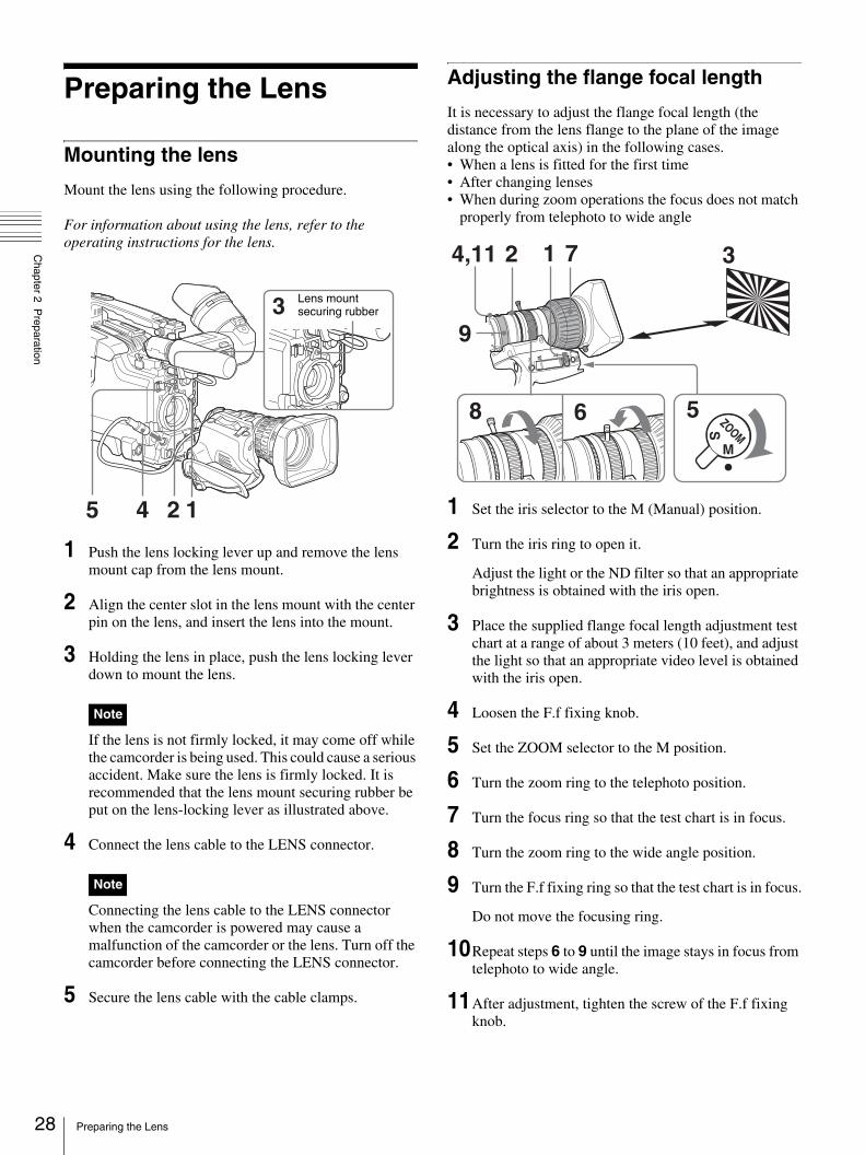
Mounting the lens
Mount the lens using the following procedure.
For information about using the lens, refer to the operating instructions for the lens.
1 Push the lens locking lever up and remove the lens mount cap from the lens mount.
2 Align the center slot in the lens mount with the center pin on the lens, and insert the lens into the mount.
3 Holding the lens in place, push the lens locking lever down to mount the lens.
If the lens is not firmly locked, it may come off while the camcorder is being used. This could cause a serious accident. Make sure the lens is firmly locked. It is recommended that the lens mount securing rubber be put on the lens-locking lever as illustrated above.
4 Connect the lens cable to the LENS connector.
Connecting the lens cable to the LENS connector when the camcorder is powered may cause a malfunction of the camcorder or the lens. Turn off the camcorder before connecting the LENS connector.
5 Secure the lens cable with the cable clamps.
Adjusting the flange focal length
It is necessary to adjust the flange focal length (the distance from the lens flange to the plane of the image along the optical axis) in the following cases.• When a lens is fitted for the first time• After changing lenses• When during zoom operations the focus does not match
properly from telephoto to wide angle
1 Set the iris selector to the M (Manual) position.
2 Turn the iris ring to open it.
Adjust the light or the ND filter so that an appropriate brightness is obtained with the iris open.
3 Place the supplied flange focal length adjustment test chart at a range of about 3 meters (10 feet), and adjust the light so that an appropriate video level is obtained with the iris open.
4 Loosen the F.f fixing knob.
5 Set the ZOOM selector to the M position.
6 Turn the zoom ring to the telephoto position.
7 Turn the focus ring so that the test chart is in focus.
8 Turn the zoom ring to the wide angle position.
9 Turn the F.f fixing ring so that the test chart is in focus.
Do not move the focusing ring.
10Repeat steps 6 to 9 until the image stays in focus from telephoto to wide angle.
11After adjustment, tighten the screw of the F.f fixing knob.
Note
Note
1
3
245
Lens mount securing rubber
RE
T
IRIS
W T MA
ZOOMM
S
9
4,11 2 1 3
8 6 5
7
Preparing the Lens

Chapter 2 P
reparation
Preparing a Power Supply
The following power supplies are recommended for the camcorder.• BP-GL65/GL95/L60S Lithium-ion Battery Pack• AC power using the AC-550, AC-DN2, AC-DN10 AC
adaptor
Using a battery pack
When a BP-GL65/GL95/L60S Battery Pack is used, the camcorder will operate continuously for the time shown below.
Before use, charge the battery pack with a charger suitable for each battery.
For details on charging procedure, refer to the battery charger operation manual.
A warm battery pack may not be able to be fully recharged.
To attach the battery pack
1 Press the battery pack against the back of the camcorder, aligning the line on the side of the battery pack with the matching line on the camcorder.
2 Slide the battery pack down until its “LOCK” arrow points at the matching line on the camcorder.
To detach the battery pack
• During recording, playback, and loading/unloading a tape, be careful never to remove the battery pack.
• Make sure to turn the camcorder off before changing the battery (except when using an AC-550 and an AC-DN2/DN10 AC adaptor together).
Using an AC adaptor
To use the AC-550 AC adaptorConnect the camcorder to the AC power supply through an AC-550 AC Adaptor as shown in the following figure, and turn the POWER switch of the AC-550 on.
Model name Operating time
BP-GL65 Approx. 180 minutes
BP-GL95 Approx. 300 minutes
BP-L60S Approx. 170 minutes
Note on using the battery pack
BP-GL65/GL95/L60S
Back of the camcorder
Align these lines.
Notes
“LOCK” arrow
Line on the camcorder
Holding the button in, pull the battery pack up.
Power switch on
to an AC power source
DC OUTAC Adaptor AC-550
DC output cable (supplied with the AC-550)
DC IN
29Preparing a Power Supply

30
Chapter 2 P
reparation
To use the AC-DN10 AC adaptorMount an AC-DN10 on the camcorder in the same way as a battery pack, then connect to the AC power supply. The AC-DN10 can supply up to 100 W of power.
Avoiding breaks in operation due to an exhausted battery
When the battery pack is becoming exhausted, you can perform battery replacement without causing a break to the camcorder operation by using an AC adaptor.
1 Turn the AC-550 AC adaptor on.
2 Connect an AC-550 AC Adaptor to an AC power source, then connect it to the DC IN connector of the camcorder (page 29).
The power source switches automatically from the battery pack to the AC adaptor connected to the DC IN connector.
There may be some noise on the video signal at the time of power source switching.
3 Replace the battery pack with a fully charged one.
Adjusting the Viewfinder
Depending on the eyesight of the operator — whether longsighted or shortsighted — the optimal position of the viewfinder image varies. Adjusting brightness, contrast, and so on, improves the visibility of the viewfinder screen.Although these adjustments may make the viewfinder image clearer, they have no effect on the output video signal from the camcorder.
Adjusting the viewfinder position
To adjust the viewfinder left-to-right position, loosen the left-to-right fixing ring, and to adjust the front-to-back position, loosen the front-to-back position locking knob.
Adjusting the eyepiece focus and the screen (brightness, contrast, and outline emphasis)
Note
to an AC power source
Viewfinder left-to-right position fixing ring
Viewfinder front-to-back position locking knob
Eyepiece focusing knob
BRIGHT control
CONTRAST control
OUTPUT/DCC switch
PEAKING control
Adjusting the Viewfinder

Chapter 2 P
reparation
To adjust the eyepiece focusFirst focus the image with the lens, then adjust the eyepiece focusing knob to get the clearest viewfinder image for your eyesight. The adjustment range is from –3 to 0 diopters.Using an optional part of the DXF-801 allows you to modify the adjustment range to –2 to +1 diopters or – 0.5 to +3 diopters.
For details, consult your Sony dealer.
To adjust contrast and brightnessCarry out these adjustments with the color bars displayed.
1 Set the OUTPUT/DCC switch to the BARS position.
The color bars appear in the viewfinder.
2 Watching the color bars, turn the CONTRAST and BRIGHT controls to adjust the contrast and brightness.
3 Return the OUTPUT/DCC switch to its original position.
To adjust the outline emphasisTurning the PEAKING control changes the degree of outline emphasis in the viewfinder image, to make focusing easier.
Removing the viewfinder
Remove any microphone from the viewfinder beforehand.
1 Pull the viewfinder connector out of the VF connector.
2 Loosen the viewfinder left-to-right position fixing ring, then pulling up the stopper, slide the viewfinder out.
To fit the viewfinderReverse the removal procedure. (You need not hold the viewfinder stopper up.)
To use the camcorder with your left eyeBy fitting a left eye adaptor to the DXF-801, you can use the camcorder with your left eye to the viewfinder.
You cannot stow the camcorder in the carrying case with the left-eye adaptor attached.
For details, consult your Sony dealer.
Attaching a 5-inch electronic viewfinder
You can attach an optional DXF-51 (5-inch) Electronic Viewfinder. To attach it, an Accessory Shoe Kit (part number A-8274-968-B) is required.
For details, contact your Sony dealer.
Remove the cover of the grip and attach the shoe and stopper screw (of the Accessory Shoe Kit).
VF connector
Note
Stopper
Viewfinder left-to-right position fixing ring
VF Cable
Guide
Fixing ring
* Supplied with the Accessory Shoe Kit
Shoe*
Stopper screw*
31Adjusting the Viewfinder

32
Chapter 2 P
reparation
Using the Shoulder Strap
1 Fit one of the clips to a shoulder strap fitting.
2 Fit the other clip to the shoulder strap fitting on the other side of the grip in the same way.
To remove the shoulder strap
Adjusting the Shoulder Pad Position
You can shift the shoulder pad backward or forward by up to 35 mm (1 7/16 inches). This adjustment helps you get the best balance for shooting with the camcorder on your shoulder.
1 Raise the lever in the center of the shoulder pad to unlock the shoulder pad.
2 Slide the shoulder pad backward or forward until it is in the most convenient position.
3 Bring down the lever to lock the shoulder pad in the selected position.
g
Clip Pull up the strap to lock the fitting.
g
Pull in the direction of the arrow while pressing here.
1,3
2
Bottom of the camcorder
Shoulder pad
Using the Shoulder Strap

Chapter 2 P
reparation
Fitting to a Tripod
First fit the VCT-U14 Tripod Adaptor to the tripod, then mount the camcorder on the tripod adaptor.
To remove a tripod
After removing the camcorder, if the tripod adaptor pin has not returned to its original position, hold down the red button and move the lever in the direction of the arrow to return the pin to its original position. It is not possible to mount a camcorder with the pin left out.
Using a Video Light
You can use the Anton Bauer Ultralight 2 or equivalent for this camcorder. Use a video light powered by 12 V with maximum power consumption of 50 W.• If you connect the video light to the LIGHT connector on
the camcorder and set the LIGHT switch to AUTO, you can turn the light on and off automatically as you start and stop the VTR operation.
• The output of the video light connector on the camcorder is controlled to 12 V even when the camcorder is supplied with 12 V or more power (through the DC IN connector or battery pack). The brightness or color temperature of the light will not change according to voltage increase.
• Do not use a video light with power consumption of over 50 W.
• The brightness or color temperature of the light will change when the supplied voltage (through the DC IN connector or battery pack) is under 12 V.
To attach the video lightFit the video light to the camcorder grip or the accessory shoe and connect the video light cable to the LIGHT connector.
Note
Slide the camcorder forward along the slot, until it clicks firmly into place.
VCT-U14 Tripod Adaptor
Tripod
Hold down the red button and pull the lever in the direction of the arrow.
Pin
Notes
33Fitting to a Tripod

34
Chapter 2 P
reparation
Preparing Audio Input System
Using the supplied microphone
1 Loosen the screw and open the microphone holder clamp.
2 Place the microphone in the microphone holder.
3 Plug the microphone cable into the MIC IN connector, then set the AUDIO IN (CH-1/CH-2) switch for the desired recording channel to FRONT.
To use the microphone detached from the camcorderYou can use the supplied microphone detached from the camcorder.
When using the supplied microphone with an extension cable, always use an external power supply type cable.
Using an external microphone
You can connect up to two external monaural microphones to the AUDIO IN CH-1/CH-2 connectors, using a CAC-12 Microphone Holder (not supplied).The procedure below is an example showing attachment of an ECM-670/672/etc. Electret Condenser Microphone.
1 Remove the fixing screws for external microphone holder.
2 Attach the CAC-12 Microphone Holder.
3 Open the CAC-12 and remove the microphone adaptor.
Clamp of the microphone holder
Place the microphone in the holder so that “UP” is at the top.
Tighten the screw.
Close the microphone holder.
Connect to the MIC IN connector.
Note
Set the AUDIO IN (CH-1/CH-2) switch for the desired audio recording channel to FRONT.
Connect to the MIC IN connector.
CAC-12
Screws removed in step 1
Preparing Audio Input System

Chapter 2 P
reparation
Use the microphone adaptor when using a small-diameter external microphone. When attaching an ECM-670, use the microphone adaptor supplied with these microphone.
4 Place an external microphone (ECM-670/672/etc. Electret Condenser Microphone or similar microphone) in the CAC-12.
5 Connect the microphone cable to the AUDIO IN CH-1 or CH-2 connector.
6 Set the switches as follows.
• Set the AUDIO IN input selection switch as indicated below, depending on the type of microphone used.- When using a microphone with an internal power
supply, set it to MIC (center).- When using a microphone with an external power
supply, set it to MIC +48V ON (right).• Set the AUDIO IN (CH-1/CH-2) switch of the
channel that the microphone is connected to REAR.
• The camcorder can use a microphone with an input level of – 60 dB. Other microphones may not be suitable for use with this camcorder due to differences in the input level.
• In order for the AUDIO IN CH-1 and CH-2 connectors on the camcorder to be able to provide a phantom 48 V power supply, female XLR connectors (3-pin) are fitted. If the microphone cable has a female connector, use an adaptor.
• When you detach a CAC-12 Microphone Holder once you have attached to the camcorder, be careful not to lose the two screws fixing the CAC-12. After detaching the CAC-12, be sure to put the two screws back into their original places.
Using a wireless microphone system
You can use the wireless microphone system including following models to record sound.• UHF Wireless Microphone
NTSC system: WRT-807B, WRT-847B PAL system: WRT-807A/B, WRT-847A/B
• UHF Synthesized Transmitter NTSC system: WRT-8B, WRT-822B PAL system: WRT-8B, WRT-822A/B
• UHF Synthesizer Tuner NTSC system: WRR-855B, WRR-861B, WRR-862B PAL system: WRR-855A/B, WRR-861A/B (in Australia and Asia only), WRR-862A/B
Microphone adaptor
Open the CAC-12.
Loosen the screw.
ECM-670/672 or similar microphone
Close the CAC-12.
Tighten the screw.m
Notes
to AUDIO IN CH-1/CH-2 connector
Monaural microphone
AUDIO IN (CH-1/CH-2) switches
35Preparing Audio Input System

36
Chapter 2 P
reparation
For details on using the wireless microphone system, see the operating instructions for the microphone and tuner.
To attach a WRR-855
1 Open the cover of the WRR connector.
2 Turn on a WRR-855, and set the MUTING to ON or OFF.
The power of a WRR-855 can be synchronized with the POWER switch of the camcorder.
3 Insert the WRR-855 into the CA-WR855.
4 Fit the attachment plate on the rear side of the CA-WR855 to the V-groove on the battery attachment interface, and then slide the CA-WR855 down until it connects to the WRR connector.
5 Set one of the AUDIO IN (CH-1/CH-2) switches to WRR (wireless).
To attach a WRR-861/862 (When using a BP-GL65/GL95/L60S Battery Pack)
1 Attach a WRR tuner fitting (not supplied, service part number A-8278-057-A) to the back of the camcorder.
1 Use a Phillips type screwdriver to tighten the four screws placed in the tuner fitting as illustrated below.
2 Loosen the adjustment screws of the tuner fitting.
3 Adjust the tuner fitting position for a BP-GL65/GL95/L60S Battery Pack to be attached, and tighten the adjustment screws to fix its position.
4 Attach the mount plate supplied with the WRR-861/862.
2 Attach the battery pack.
For details about attaching the battery pack, see “Using a battery pack” on page 29.
3 Mount the tuner on the WRR tuner fitting.
For details about the WRR tuner fitting (part number A-8278-057-A), contact your Sony service representatives.
WRR connector
Fasten the screws (supplied with the WRR-855).
CA-WR855
Phillips type screwdriver
BP-GL65/GL95/L60S
Back of the camcorder
Mount plate (supplied with WRR-861/862)
Adjustment screws
WRR-861/862
Preparing Audio Input System

Chapter 2 P
reparation
4 Connect the tuner power cord to the DC OUT connector of the camcorder, and the audio output cable to the AUDIO IN CH-1 or CH-2 connector.
5 Set the switches as below.
• Set the AUDIO IN input selection switch to MIC for the channel to which the audio out cable is connected.
• Set the AUDIO IN (CH-1/CH-2) switch for the channel to which the audio output cable is connected to REAR.
Connecting line input audio equipment
1 Connect an audio mixer or other external audio system component to the AUDIO IN CH-1/CH-2 connector as shown below.
2 Set the AUDIO IN input selection switch to LINE for the channel to which the external audio equipment is connected.
Selection of the recording audio inputSet the AUDIO IN (CH-1/CH-2) switch to REAR for the channel to which the external audio equipment is connected.If you record and adjust both channel 1 and 2, set both AUDIO IN (CH-1/CH-2) switches to REAR.
Connecting the Remote Control Unit (DSR-450WS/450WSP only)
Connecting the RM-B150/B750 Remote Control Unit enables remote control of the principal camera and VTR functions.Connecting the remote control unit to the REMOTE connector (8-pin) automatically puts the camcorder into remote control mode. If you disconnect the remote control unit, the remote control mode is cancelled.
Camcorder switch functions when the remote control unit is connectedThe following switches on the camcorder do not function.• GAIN switch• OUTPUT/DCC switch• WHITE BAL switch• AUTO W/B BAL switch• SHUTTER switch• REC button (the VTR button on the lens and the
ASSIGN switch to which the REC SWITCH function is assigned) when the RM REC START item is set to RM on the FUNCTION 3 page of the MAINTENANCE menu.
For details of the function of the REC button, see “Function of the REC button when the remote control unit is connected” on page 38.
Paint adjustment when the remote control unit is connectedThe settings of the paint adjustment that were in effect the last time the remote control unit was used are recalled.
LINE MIC+48V ON
FRONT
AUDIO IN
REARWRR
To audio mixer, etc.
AUDIO IN (CH-1/CH-2) switches: Set to REAR.
AUDIO IN CH-1/CH-2 connectors
AUDIO IN input selection switch: Set to LINE.
RM-B150/B750
Remote connector
Remote control cable
37Connecting the Remote Control Unit (DSR-450WS/450WSP only)
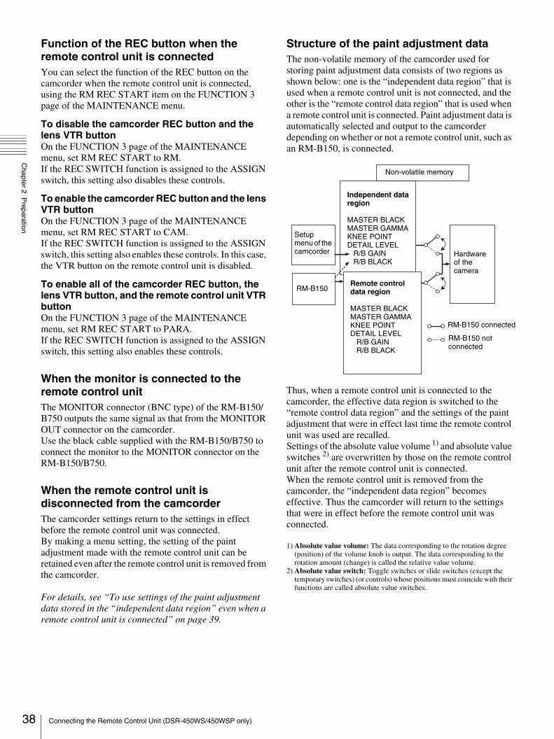
38
Chapter 2 P
reparation
Function of the REC button when the remote control unit is connectedYou can select the function of the REC button on the camcorder when the remote control unit is connected, using the RM REC START item on the FUNCTION 3 page of the MAINTENANCE menu.
To disable the camcorder REC button and the lens VTR buttonOn the FUNCTION 3 page of the MAINTENANCE menu, set RM REC START to RM.If the REC SWITCH function is assigned to the ASSIGN switch, this setting also disables these controls.
To enable the camcorder REC button and the lens VTR buttonOn the FUNCTION 3 page of the MAINTENANCE menu, set RM REC START to CAM.If the REC SWITCH function is assigned to the ASSIGN switch, this setting also enables these controls. In this case, the VTR button on the remote control unit is disabled.
To enable all of the camcorder REC button, the lens VTR button, and the remote control unit VTR buttonOn the FUNCTION 3 page of the MAINTENANCE menu, set RM REC START to PARA. If the REC SWITCH function is assigned to the ASSIGN switch, this setting also enables these controls.
When the monitor is connected to the remote control unitThe MONITOR connector (BNC type) of the RM-B150/B750 outputs the same signal as that from the MONITOR OUT connector on the camcorder.Use the black cable supplied with the RM-B150/B750 to connect the monitor to the MONITOR connector on the RM-B150/B750.
When the remote control unit is disconnected from the camcorderThe camcorder settings return to the settings in effect before the remote control unit was connected.By making a menu setting, the setting of the paint adjustment made with the remote control unit can be retained even after the remote control unit is removed from the camcorder.
For details, see “To use settings of the paint adjustment data stored in the “independent data region” even when a remote control unit is connected” on page 39.
Structure of the paint adjustment dataThe non-volatile memory of the camcorder used for storing paint adjustment data consists of two regions as shown below: one is the “independent data region” that is used when a remote control unit is not connected, and the other is the “remote control data region” that is used when a remote control unit is connected. Paint adjustment data is automatically selected and output to the camcorder depending on whether or not a remote control unit, such as an RM-B150, is connected.
Thus, when a remote control unit is connected to the camcorder, the effective data region is switched to the “remote control data region” and the settings of the paint adjustment that were in effect last time the remote control unit was used are recalled.Settings of the absolute value volume 1) and absolute value switches 2) are overwritten by those on the remote control unit after the remote control unit is connected.When the remote control unit is removed from the camcorder, the “independent data region” becomes effective. Thus the camcorder will return to the settings that were in effect before the remote control unit was connected.
1) Absolute value volume: The data corresponding to the rotation degree (position) of the volume knob is output. The data corresponding to the rotation amount (change) is called the relative value volume.
2) Absolute value switch: Toggle switches or slide switches (except the temporary switches) (or controls) whose positions must coincide with their functions are called absolute value switches.
Non-volatile memory
Independent data region
MASTER BLACKMASTER GAMMAKNEE POINTDETAIL LEVEL R/B GAIN R/B BLACK
Remote control data region
MASTER BLACKMASTER GAMMAKNEE POINTDETAIL LEVEL R/B GAIN R/B BLACK
Setup menu of the camcorder
RM-B150
Hardware of the camera
RM-B150 connected
RM-B150 not connected
Connecting the Remote Control Unit (DSR-450WS/450WSP only)

Chapter 2 P
reparation
To use settings of the paint adjustment data stored in the “independent data region” even when a remote control unit is connectedSet RM COMMON MEMORY to ON on the FUNCTION 3 page of the MAINTENANCE menu.In this case, the settings stored in the “independent data region” will be renewed according to the change made by remote control unit. Thus, the settings of the paint data made with the remote control unit can be retained even if the remote control unit is removed. However, if the switch position on the remote control unit differs from the one on the camcorder, the switch position on the camcorder takes precedence over that on the remote control unit.
For details on menu operations, see “Basic menu operations” on page 93.
To avoid changing video adjustment data when a remote control unit is connectedSet RM COMMON MEMORY to ON on the FUNCTION 3 page of the MAINTENANCE menu, and set all the volume on the remote control unit to the relative value mode.
For details, refer to the operation manual supplied with the remote control unit.
39Connecting the Remote Control Unit (DSR-450WS/450WSP only)

hapter
40
Chapter 3 C
onnections
CConnections
Connecting a Monitor
As illustrated below, you can connect a color video monitor to the MONITOR OUT or VIDEO OUT connector of the camcorder.
When a CBK-SD01 SDI Output Board is installed (DSR-450WS/450WSP only)If a color video monitor provided with an SDI input connector is used, select SDI as the output signal of the VIDEO OUT connector and connect the camcorder to the SDI IN connector of the color video monitor.The camera display image is output to the CBK-SD01 SDI Output Board even when playing a recorded image.
• Playing the tape on the camcorder mutes the audio signal portion of the SDI output.
• You can select either VBS or SDI for the output signal of the VIDEO OUT connector, depending on the input connector used on the monitor. See 1) and 2) in the illustration above.
For details about settings, see “Selecting the output signals (DSR-450WS/450WSP only)” on page 104.
The items displayed on a monitor are same as the ones on the viewfinder. For details, see “Status display on the viewfinder screen” on page 21.
Notes
Color video monitor
VIDEO IN connector 1) or SDI IN connector (DSR-450WS/450WSP only) 2)
DSR-400/400P/450WS/450WSP
MONITOR OUT connector or VIDEO OUT connector (DSR-450WS/450WSP only)
1) When VBS is selected as the output signal of the VIDEO OUT connector2) When SDI is selected as the output signal of the VIDEO OUT connector
(only when a CBK-SD01 is installed)
Connecting a Monitor

Chapter 3 C
onnections
Using an i.LINK Connection
Using the (i.LINK) DV OUT connector, you can connect external recording equipment to the camcorder. In this section, connections to equipment using DVCAM or DV format are explained.
Depending on the equipment connected, you may be able to record in a format different from that of the camcorder. However, the recording function using different formats is limited.
For details, see “Usable cassettes” on page 47.
Settings required for an i.LINK connection
When connecting via an i.LINK cable (DV cable), change the following settings depending on the connection.
i.LINK CTL settingSelects whether or not to control recording (start and stop) on the external equipment connected to the (i.LINK) DV OUT connector from the camcorder. Select the setting from the following on the FUNCTION 3 page of the MAINTENANCE menu. The factory setting is REC/P.ALL: An external equipment is controlled from the
camcorder while it records, pauses, or stops.REC/P (REC/PAUSE): An external equipment is
controlled from the camcorder while it records or pauses.
OFF: No control from the camcorder.
REC TRIGGER switchSets the function of the REC button on the camcorder or the VTR button on the lens when an external VTR is connected to the (i.LINK) DV OUT connector. Set to INT ONLY when you need to do cut editing or making a copy of a tape using the (i.LINK) DV OUT connector.PARALLEL: Operates both internal and external VTRs
simultaneously.INT ONLY: Operates the internal VTR only. External
VTR operation is performed locally. EXT ONLY: Operates the external VTR only. The
TALLY indicator on the camcorder lights up when the external VTR is in recording mode.
When there is no equipment connected to the (i.LINK) DV OUT connector on the camcorder, the setting of the REC TRIGGER switch does not affect the internal VTR.
Making a backup of the images being recorded
The audio and image being recorded can be backed up on an external VTR through i.LINK, at the same time it is being recorded on the camcorder.
Example of connection
When the scan mode is 24P, video images, audio, or time code output via the i.LINK connection may not be continuous (DSR-450WS only).
To record the same material using the internal VTR of the camcorder and on an external VTR simultaneously
1 Set the REC TRIGGER switch to PARALLEL.
2 Check the settings of an external VTR and set the i.LINK CTL to the same settings.
3 Press the REC button.
Recording starts on both the internal VTR of the camcorder and the external VTR.
If recording on the camcorder and the external VTR starts at the same time, the recording starting points differ because of variation due to the external VTR connected. Also, it is recommended that you use internal mode as the time code generator mode for an external VTR. If you synchronize the time code generator of the camcorder using external mode, the time code may not be continuous.
Note
Note
Note
Note
External VTR
DSR-400/400P/450WS/450WSP
DSR-50/PD170, etc.
i.LINK cable (DV cable)
41Using an i.LINK Connection

42
Chapter 3 C
onnections
To record by clip using the internal VTR while simultaneously recording on an external VTRWhile recording material consecutively by time on an external VTR, the material needed for editing can be recorded clip by clip using the internal VTR of the camcorder.
1 Set the REC TRIGGER switch to INT ONLY.
2 Press the recording button of the external VTR.
Recording starts on the external VTR.
3 Press the REC button on the camcorder.
Recording starts on the internal VTR. Pressing the REC button switches between recording and pausing using the internal VTR.
To check the playback image recorded on an external VTRYou can check the playback image recorded on an external VTR that is connected to the camcorder for backup.
1 Connect the camcorder to the external VTR using an i.LINK cable (DV cable).
2 Set the REC TRIGGER switch to PARALLEL or EXT ONLY.
3 Set the internal VTR of the camcorder to stop mode.
4 Start playback on the external VTR.
The i.LINK on the camcorder changes to input mode, and the playback image from the external VTR is displayed on the viewfinder and the LCD monitor, and through the MONITOR OUT connector.
• The i.LINK on the camcorder changes to input mode only when the connected external equipment is played back. (When the REC TRIGGER switch is set to INT ONLY, the i.LINK does not change to input mode.)
• The playback image from the external VTR cannot be recorded using the internal VTR of the camcorder.
• Depending on the external equipment connected, the playback image may be overlapped or skipped over if the playback signal contains jitter. However, this is not a malfunction.
• In order to check the video image when a DSR-1500A/1800A/2000A or similar equipment is connected to the camcorder, it is necessary to set the input to a setting other than i.LINK. When the input is set to i.LINK, i.LINK is only used for input and no signal is output via the i.LINK connection. Therefore, a gray image is displayed on the camcorder.
Using the camcorder as a feeder
To copy digitally from the camcorder to the VTR without the editing functionUsing an i.LINK cable (DV cable) to connect a digital video cassette recorder with an i.LINK connector to the camcorder, digital copy of video and audio can be carried out.
Example of connection
1 Make the settings below to prepare the external VTR.
• Set REC MODE to the same recording mode as that of the camcorder.
• In NTSC color system, when the recording mode is set to DVCAM, select either DF or NDF.
• Set AUDIO MODE to either 4-channel or 2-channel mode, according to the tape that is played on the camcorder.
2 Pause recording on the external VTR.
3 Play the tape on the camcorder.
4 Check the playback on the camcorder, and when playback reaches the scene that you want to record, start recording again on the external VTR.
The copy to the external VTR starts.
5 When copy to the external VTR is finished, release the recording pause on the external VTR, and then stop playback of the tape on the camcorder.
For details on the external VTR, see the instruction manual supplied with the external VTR.
Notes
External VTR
DSR-1800A/45, etc.
DSR-400/400P/450WS/450WSP
i.LINK cable (DV cable)
Using an i.LINK Connection

Chapter 3 C
onnections
To control the camcorder from the VTR using the editing functionBy connecting a VTR with an i.LINK connector to the (i.LINK) DV OUT connector of the camcorder using an i.LINK cable (DV cable), you can control playback and recording of the camcorder and perform cut editing and digital copy.
Example of connection
1 Set the REC TRIGGER switch to INT ONLY.
2 Make the settings below to prepare the external VTR.
When using DSR-2000A, press the i.LINK button on the remote control setting section.
To use the automatic copying function of DSR-2000A, it is necessary to set the recording format of the camcorder to DVCAM on the VTR MODE page of the MAINTENANCE menu.
For details on the external VTR, see the instruction manual supplied with the external VTR.
To control the camcorder from a non-linear editing systemUsing the i.LINK cable (DV cable), you can transfer video and audio signals to a non-linear editing system from the camcorder. Editing software that supports the selected recording format (DVCAM or DV) must be used.
Example of connection
1 Set the REC TRIGGER switch to INT ONLY.
2 Operate the PC to set up the non-linear editing software.
For details, see the software’s manual.
• Video edited using a non-linear editing system cannot be recorded on tape using the camcorder via an i.LINK cable (DV cable).
• A tape recorded with a non-continuous time code may not be able to be captured frame by frame using a non-linear editing system.
Note
External VTR
DSR-400/400P/450WS/450WSP
DSR-2000A, etc.
i.LINK cable (DV cable)
Notes
Computer with editing software that supports DVCAM or DV format installed
DSR-400/400P/450WS/450WSP
i.LINK cable (DV cable)
PC
43Using an i.LINK Connection

44
Chapter 3 C
onnections
Other Connections
Connecting a number of camcorders
When using two or more synchronized camcorders, connect an external sync signal to the GENLOCK IN connector, supplying a VBS or BS signal. The camcorder will then operate synchronized to this signal.You can adjust the synchronization using the GENLOCK page of the MAINTENANCE menu.When a CBK-SD01 SDI Output Board is installed in the DSR-450WS/450WSP, it is necessary to set REAR BNC OUT SEL to VBS on the OUTPUT page of the OPERATION menu.
• When a CBK-SC01 Composite Input Board (not supplied) is installed, set REC VIDEO SOURCE to CAM on the SOURCE SEL page of the OPERATION menu.
• When connecting a number of camcorders and synchronizing their time codes, wait until the reference camcorder becomes stable (a state where a normal picture appears on the viewfinder or the LCD monitor), and then connect the other camcorders.
Example 1: When camcorder 2 is synchronized with the signal of camcorder 1
Example 2: When camcorder 1 and 2 are synchronized with the signal of a DME switching device, etc.
Notes
DSR-450WS/450WSP
DSR-400/400P/450WS/450WSP
BNC cable
to VIDEO OUT
to MONITOR OUT Camcorder 1
to video input connector
to video input connector
to MONITOR OUT/VIDEO OUT
to GENLOCK INCamcorder 2
BNC cable
BNC cable
Portable VTR
DME switching device, etc.
DSR-400/400P/450WS/450WSP DSR-400/400P/450WS/450WSPCamcorder 1 Camcorder 2
to synchronized signal output connector *
to GENLOCK IN
to MONITOR/VIDEO OUT
BNC cable
to video input connector
to GENLOCK INto MONITOR/
VIDEO OUT
to synchronized signal output connector *
to video input connector
BNC cableBNC cableBNC cable
* Either the BB (Black Burst) signal or the Color Bar signal, etc. can be used as a synchronized signal.
Other Connections

hapter
CRecording and PlaybackChapter 4 R
ecording and Playback
Inserting a Cassette
The camcorder can use standard-size and mini-size DVCAM/DV cassettes. For details about usable cassette, see“Usable cassettes” on page 47.
1 Set the POWER switch to ON.
2 While sliding the OPEN lever in the direction of the arrow, open the cassette lid.
3 Insert the cassette with the cassette window (on the front) facing outward and the REC/SAVE switch facing upward.
Check for tape slack before inserting the cassette.
To insert a mini-size cassetteInsert the cassette with the cassette window (on the front) facing outward. Push the cassette between the both guides.
4 Close the cassette lid until it clicks.
To eject a cassetteFollow the procedure above, and take out the cassette by pressing the EJECT button in step 3.
• Before inserting a cassette, make sure that there is no cassette in the cassette compartment. Inserting two cassettes by mistake may cause a malfunction.
• Internal parts of the camcorder may become bent or otherwise damaged if you attempt to insert a mini-size cassette in the wrong direction (such as with the cassette turned backside front so the reel holes face the cassette holder window or with the cassette turned sideways so that a short side enters first).
• If a cassette is not inserted completely or gets stuck when being inserting, take out the cassette and reinsert it. If your insert a cassette forcibly, the cassette may not be
OPEN lever
Press the center of the cassette.
REC/SAVE switch
Notes
GuidesMini-size cassette match marks
Press the lid firmly until it clicks.
45Inserting a Cassette

46
Chapter 4 R
ecording and Playback
inserted in the correct position or may cause a malfunction.
• When inserting a cassette, hold the center of the cassette and insert it straight toward the compartment. Holding the side of the cassette may cause it to be inserted incorrectly.
• When inserting a cassette, put the camcorder on a horizontal and stable surface.
Basic Procedure for Shooting
1 Set the POWER switch to ON.
2 Set the FILTER selector and the 5600K button appropriately for the lighting conditions.
* The range over which the subject is sharply in focus. Thus, “reducing the depth of field” means that the range is reduced as well, and “increasing the depth of field” means that it is increasing as well.
3 Check the switch settings on the camcorder.
4 Check the settings in the menu.
5 Check the lens settings and flange focal length adjustment (page 28).
6 Adjust the eyepiece focus, and the contrast and brightness of the viewfinder image (page 30).
7 Check the sound system settings.
• Microphone connections (page 34)• Settings on the VTR section (page 14)
FILTER selector setting
Examples of shooting conditions
1 (CLEAR) Studio halogen lighting (incandescent)
2 (1/4 ND) Cloudy or rainy outdoor shooting, or to reduce the depth of field*
3 (1/16 ND) Sunlight
4 (1/64 ND) To reduce the depth of field in sunlight
1
2
8
11 12,13
Basic Procedure for Shooting

Chapter 4 R
ecording and Playback
8 If required, switch on the center marker and/or safety zone in the viewfinder image.
For details, see “Setting the marker display” on page 100.
Also, press the ZEBRA button to display zebra pattern in the viewfinder.
9 If necessary, adjust the white balance and black balance (page 50).
10If necessary, adjust the iris and gain.
For details about the adjustment of iris, see “Iris ring” on page 19, “Instant automatic iris adjustment button” on page 19, and “Adjusting the iris” on page 55.
For details about the adjustment of gain, see “GAIN switch” on page 11, and “Setting gain values for the GAIN switch positions” on page 103.
11Turn the focusing ring so that the subject is sharply in focus.
12Setup the VTR section according to your shooting objects, then start recording by pressing the REC button.
• During recording, the REC/TALLY indicator(s) in the viewfinder light(s), and “REC” appears on the viewfinder screen.
• You can use the AUDIO LEVEL knob on the front of the camcorder to manually adjust the channel 1 audio level. To do this, you must first set up the VTR section to enable manual adjustment of the audio recording level (page 57).
13To pause recording, press the REC button again.
Recording
Usable cassettes
It is recommended to use the DVCAM cassettes listed below for this camcorder.
The “*” in each model name is actually “ME” (indicating that a cassette memory is contained), or “N” (indicating that no cassette memory is contained).The numbers in the model names show maximum recording/playback time (minutes) for each model. For example, the maximum recording/playback time of the PDV-184* is 184 minutes.
If you insert an incorrect type of cassette, it will be automatically ejected.
DVCAM cassettesThe following figure illustrates the DVCAM cassettes’ appearance.
Notes on using cassettes• Before storing the cassette, rewind the tape to the
beginning and be sure to put the cassette in its storage case, preferably on end instead of flat on its side. The storage case of a DVCAM cassette is specially designed to ensure a long-period storage of the tape. Storing a cassette in any other condition (not rewound, out of its case, etc.) may cause the video and audio contents to become damaged over time.
• If the cassette memory connector (contact point) becomes dirty, connection problems may occur and cause a loss of functions. Remove away any dust or dirt from this area before using the cassette.
• If the cassette is dropped on the floor or otherwise receives a hard impact, the tape may become slackened
Model name Size
PDV-184*/124*/94*/64*/34* Standard size
PDVM-40*/32*/22*/12* Mini size
Note
Standard size
Mini size
REC/SAVE switch
Cassette memory
47Recording

48
Chapter 4 R
ecording and Playback
and may not record and or play back correctly. For instructions on removing tape slack, see next page.
• Follow the instructions in “Inserting a Cassette” on page 45 to insert a cassette, or the camcorder may be damaged.
To prevent accidental erasureSet the REC/SAVE switch to SAVE to prevent accidental erasure of recorded contents.
If you insert a cassette into the camcorder when the REC/SAVE switch is set to SAVE, the camcorder will not record when you press the REC button.
To enable recordingSet the REC/SAVE switch back to REC.
To check the tape for slack Turn the reel gently with a paper clip, etc., in the direction shown by the arrow. If the reel does not move, there is no slack. Insert the cassette into the cassette holder, and after about 15 seconds take it out.
Compatibility of DVCAM and DV formatsThis camcorder can also use the consumer DV format in addition to the DVCAM format (only SP mode is available for DV format, you cannot record/play in LP mode of the DV format). Here explained are the differences, compatibility, and limitations on editing about DVCAM and DV formats.
Differences between DVCAM and DV formats
* There are two modes for audio recording, lock mode and unlock mode. In lock mode, the sampling frequencies of audio and video are synchronized. In unlock mode, which consumer DV format adopts, the two sampling frequencies are independent. Therefore, lock mode is more effective than unlock mode in digital processing and smooth transition during audio editing.
Audio with sampling frequency 16 bit: 32 kHz and 44.1 kHz cannot be recorded on this camcorder.
Compatibility on cassettesThe recording format of picture is defined according to recorder’s format as described below.
• Though DV cassettes can be used for recording in DVCAM format, we recommend you to use DVCAM cassettes to get the most out of high reliability of DVCAM format.
• When you record using DV cassettes in DVCAM format, the recording time of DV cassettes is 2/3 shorter than that indicated on the DV cassettes.
Compatibility on playbackSome tapes cannot be played back on DVCAM or DV video equipment.
RECSAVE
REC/SAVE switch
Set to SAVE.
Paper clip, etc.
Reel
Item DVCAM DV
Track pitch 15 µm 10 µm
Audio sampling frequency
12 bit: 32 kHz16 bit: 48 kHz
12 bit: 32 kHz16 bit: 32 kHz, 44.1 kHz, 48 kHz
Audio recording mode*
Lock mode Unlock mode
Time code Drop frame systemor Non-drop frame system (SMPTE time code)
Drop frame system (or Non-drop frame system when recording in DV format)
Note
Recorder’s format
Cassette that is used
Recording format
DVCAM DVCAM tapeDV tape
DVCAM
DV DVCAM tapeDV tape
DV
Tape On DV video equipment
On DVCAM video equipment
DV-formatted Can be played back.
Can be played back only when recorded in SP mode.
DVCAM-formatted
Some equipment may be able to play back.
Can be played back.
Recording

Chapter 4 R
ecording and Playback
Compatibility on editing using DV connectorsWhen this digital camcorder is connected to other DVCAM or DV video equipment using DV cable (i.LINK cable), the recording format of edited tapes is defined according to recorder’s format as described below. Read through “Limitations on editing” before editing, because you may find the limitations when you use the tapes edited in some conditions.
1) When using the DVCAM video equipment to carry out DV dubbing of a tape recorded in DV format, the tape produced will be in DVCAM format as follows:- Audio recording mode will be unlock mode.
(A tape in lock mode may be copied on some video equipment. For details, see the instruction manual supplied with your video equipment.)
- The time code format will be partly maladjusted. (There will be no effect on the recorded picture except in certain case.)
2) If the tape that is to be dubbed is DVCAM formatted tape as explained in 1), the tape produced will be in DVCAM format as follows:- Audio recording mode will be unlock mode.- The time code format will be partly maladjusted.
3) Some DV video equipment may be able to play back a DVCAM-formatted tape. However, even if the tape is played back, contents of the playback cannot be guaranteed. Therefore, if an appropriate DVCAM-formatted tape is used for playback, the tape produced will be in DVCAM format and will have a partly maladjusted time code format.
4) The audio recording mode of the edited tape is lock mode. If the tape that is to be dubbed is a DVCAM formatted tape as explained in 1), the audio recording mode of the edited tape is unlock mode.
5) Depending on model of video equipment, you may not be able to edit.
When you use a tape as explained in 1) to 3) above, you may find limitations regardless of the format of the player and recorder.
Limitations on editingWhen using a tape copied or edited using DV connectors, you will find the following limitations when editing, because of the difference in DVCAM and DV formats.• Due to the difference of a track pitch, you cannot edit on
DV-formatted tapes using DVCAM video equipment.• You cannot edit DVCAM-formatted tapes recorded in
unlock mode using some DVCAM video equipment. In this case, copy the tape again using the audio/video jacks.
Selecting the recording format
Before recording, it is necessary to select the recording format from either DVCAM or DV SP format.
• If recording formats are mixed in one tape, the part where the video images recorded in different formats will be distorted.
• When shooting in DV SP format, the video recorded in back space editing (recording several scenes continuously) may not be smooth. To shoot reliable video, it is recommended that you use a DVCAM cassette and set REC FORMAT to DVCAM (see the following procedure).
1 Display the VTR MODE page of the MAINTENANCE menu.
For details on menu operations, see “Basic menu operations” on page 93.
2 Press the MENU knob. Then turn the MENU knob to move b to REC FORMAT, and press the MENU knob again.
b changes to z, and z changes to ?.
3 Turn the MENU knob to display the desired recording format (DVCAM or DV SP), then press the MENU knob.
z changes to b, ? changes to z, and the selection is set.
Source tape Player’s format
Recorder’s format
Recording format
DV (only in SP mode)
DVCAM DVCAMDV
DVCAM 1)
DV
DV DV DVCAMDV
DVCAM 1)
DV
DVCAM 2) DVCAM DVCAMDV
DVCAMDV 4)
DVCAM 2) DV 3) DVCAMDV
DVCAM 5)
DV 4)
Note
Notes
?M05 VTR MODE TOP
REC TALLY BLINK : ON
STBY OFF TIMER : 1MIN
REC FORMAT : DVCAM
SETUP ADD : ON
49Recording

50
Chapter 4 R
ecording and Playback
Adjusting the black balance/white balance
To ensure excellent image quality when using this camcorder, conditions may require that both the black balance and the white balance be adjusted.If the black balance or white balance adjustment is started, messages that report on the progress and results are displayed on the viewfinder screen when the VF DISP MODE item is set to 2 or 3 on the VF DISP 1 page of the OPERATION menu.
Black balance and white balance adjustment values that are automatically set by the camcorder and the various settings are stored in the camcorder memory and retained even when the power is turned off.
To adjust the black balanceThe black balance will require adjustment in the following cases.• When the camcorder is used for the first time• When the camcorder has not been used for a long time• When the camcorder is used under conditions in which
the surrounding temperature has changed greatly• When the GAIN switch (L/M/H) values have been
changed by using the OPERATION menuIt is not usually necessary to adjust the black balance when using the camcorder after it has been off.In automatic black balance mode, adjustments are performed in the following order: clamp level, black set, and black balance.Note that the automatic black balance adjustment includes a function to correct minor bright or dark points of light (red, blue, or green) that appear on the CCDs, in addition to the normal black balance operation.
1 Power the camcorder on, and set the OUTPUT/DCC switch to CAM.
2 Push the AUTO W/B BAL switch to BLACK and release the switch.
The switch returns to the center position, and the adjustment is executed.During adjustment, the following message is displayed on the viewfinder screen.
The black balance adjustment ends in a few seconds with the message “ABB: OK” and the adjustment value is automatically stored in memory.
• During the black balance adjustment, the iris is automatically closed.
• During the black balance adjustment, the gain selection circuit is automatically activated so you may see flickering on the viewfinder screen, but this is not a malfunction.
If automatic black balance adjustment cannot be madeIf the black balance adjustment cannot be completed normally, an error message will appear for about 3 seconds on the viewfinder screen.
If any of the above error messages is displayed, retry the black balance adjustment. Keep pushing the AUTO W/B BAL switch to BLACK until “-BLACK SET-” appears after “-BLACK BALANCE-” appears. If the error message occurs repeatedly, contact your Sony service representatives.
Note
12
Notes
Error message Meaning
ABB: NGIRIS NOT CLOSED
The lens iris did not close. Check if the lens cable is connected properly.
ABB: NGTIME LIMIT
Adjustment could not be completed within the standard number of attempts.
ABB: NGR (or G or B): OVERFLOW
The difference between the reference value and the current value is so great that it exceeds the range.
ABB:EXECUTING
-BLACK SET-
The messages change in sequence:-BLACK SET- r-BLACK BALANCE-
Recording

Chapter 4 R
ecording and Playback
To adjust the white balanceIt is necessary to adjust the white balance each time the principal lighting source changes.
1 Set the switches and selectors as shown in the figure below.
* White balance setting values are stored in memory B only when the WHITE SWITCH <B> item is set to MEM on the FUNCTION 2 page of the OPERATION menu.
2 Set the FILTER selector and the 5600K button to suit the lighting conditions.
FILTER selector setting and CC filter selection are as follows.
If the setting of the FILTER selector is changed, a message reporting the setting appears for about 3 seconds in the setting change and adjustment progress message display area of the viewfinder screen (when the display mode is set to 3 on page 99).
3 Place a white test card under the same lighting conditions as for the subject to be shot and zoom up to it.
Alternatively, any white object such as a cloth or a wall can be used.The absolute minimum white area is as follows.
Make sure there are not bright spots in the rectangle.
4 Adjust the lens iris.
Manually adjusted lens: Set the iris to an appropriate setting.Lens with automatic iris: Set the automatic/manual switch on the lens to automatic.
5 Push the AUTO W/B BAL switch to WHITE, and then release the switch.
The switch returns to the center position, and the adjustment is executed.
During adjustment, the message “AWB: EXECUTING” is displayed on the viewfinder screen (when the display mode is set to 2 or 3 (page 99)).
The white balance is adjusted in about one second, and the message “ABB: OK” appears. The adjustment setting is automatically stored in the memory (A or B) that was selected in step 1.
Filter setting Lighting conditions
1 (CLEAR) Studio halogen lighting (incandescent)
2 (1/4 ND) Cloudy or rainy outdoor shooting, or to reduce the depth of field
3 (1/16 ND) Sunlight
4 (1/64 ND) To reduce the depth of field in sunlight
FILTER selector
WHITE BAL switch: A or B*
OUTPUT/DCC switch: CAM
GAIN switch: Set as low as possible.
Note
Rectangle centered on the screen. The lengths of the sides are 70% of the length and width of the screen.
The white object must be within the rectangle and have an area of at least 10% of the screen.
AUTO W/B BAL switch
AWB:OK
. KApproximate color temperature of the subject
51Recording

52
Chapter 4 R
ecording and Playback
If the camera has a zoom lens with an automatic iris, the iris may hunt.* To prevent this, adjust the iris gain knob (indicated as IG, IS, or S) on the lens.
For details, refer to the lens operation manual.
* Hunting: Repeated brightening and darkening of the image, resulting from repeated response to automatic iris control.
If the automatic white balance adjustment cannot be madeIf the white balance adjustment cannot be completed normally, an error message will appear for about 3 seconds on the viewfinder screen (in display mode 2 or 3).
If any of the above error messages is displayed, retry the white balance adjustment. If the error message occurs repeatedly, contact your Sony service representatives.
If you have no time to adjust the white balanceSet the WHITE BAL switch to PRST.The white balance is automatically set as follows, depending on the 5600K button setting.• 5600K ON (lights on): 5600K• 5600K OFF (lights off): 3200K
About the white balance memoryValues stored in memory are held until the white balance is next adjusted.There are two sets of white balance memories, A and B, and adjustments for each of the filters can be automatically stored in the memory corresponding to the setting (A or B) of the WHITE BAL switch. The camcorder has four built-in filters, so a total of eight (4 × 2) adjustments can be stored. The number of memories allocated to each of A and B can be limited to one by setting the WHT FILTER INH item to ON on the FUNCTION 3 page of the MAINTENANCE menu. In this case, the memory contents are not linked to the filter settings. If the WHITE BAL switch is set to B, and on the FUNCTION 2 page of
the OPERATION menu, the WHITE SWITCH <B> item is set to ATW, the ATW function is activated to automatically adjust the white balance of the picture being shot for varying lighting conditions.
If a memory error occursIf the error message “: STORED DATA: NG” flashes on the viewfinder screen when the camcorder is turned on, the white balance memory contents have been lost. Adjust the white balance again. Contact your Sony representative if this message continues to appear even after the white balance have been adjusted again.
Setting the electronic shutter
This section describes the shutter modes that can be used with the electronic shutter of the camcorder, and describes the procedure for selecting the shutter speed and shutter mode.
About the shutter modesThe shutter modes that can be used with the electronic shutter and the shutter speeds that can be selected are listed below.
Note
Error message Meaning
WHITE: NGLOW LEVEL
The white video level is too low. Either open the lens iris or increase the gain.
WHITE: NGCOLOR TEMP HIGH
The color temperature is too high. Select a suitable setting for the 5600K button.
WHITE: NGCOLOR TEMP LOW
The color temperature is too low. Select a suitable setting for the 5600K button.
WHITE: NGTIME LIMIT
Adjustment could not be completed within the standard number of attempts. Try to adjust again. If fails a few times, contact your Sony dealer.
WHITE: NGPOOR WHITE AREA
The white area could not be checked.
WHITE: NGOVER LEVEL
The white video level is too high. Either stop down the lens iris or change the ND filter.
Shutter mode
Shutter speed Application
Standard DSR-400/450WS
Scan Mode: I 1/100, 1/125, 1/250, 1/500, 1/1000, 1/2000 (sec.)Scan Mode: PsF 1)
1/40, 1/60, 1/120, 1/125, 1/250, 1/500, 1/1000, 1/2000 (sec.)Scan Mode:24P 2)
1/32, 1/48, 1/96, 1/125, 1/250, 1/500, 1/1000, 1/2000 (sec.)
For shooting fast-moving subjects with little blurring.
DSR-400P/450WSP
Scan Mode: I 1/60, 1/125, 1/250, 1/500, 1/1000, 1/2000 (sec.)Scan Mode: PsF 1)
1/33, 1/50, 1/100, 1/125, 1/250, 1/500, 1/1000, 1/2000 (sec.)
Recording

Chapter 4 R
ecording and Playback
1) Only for the DSR-450WS/450WSP2) Only for the DSR-450WS3) The SLS mode can only be selected when the CCD scan mode (page 108)
is set to I (interlace scan) (DSR-450WS/450WSP only).
• Whatever the operating mode of the electronic shutter, the sensitivity of the CCD decreases with increasing shutter speed.
• When the automatic iris is used, the iris opens wider as the shutter speed increases, thus reducing the depth of field.
• Under artificial light, particularly fluorescent or mercury lamps, the light intensity may appear to be constant, but the red, green, and blue intensities are actually changing in synchronization with the frequency of the power supply causing flicker. Using an electronic shutter under such lighting could make the flicker even worse. Color flicker is particularly likely to happen when the power supply frequency is 60 Hz. However, if the power frequency is 50 Hz, setting the shutter speed to 1/100 can reduce this flicker.
• When a bright object is shot in EVS or ECS mode in such a manner that it fills the screen, the upper edge of the picture may have poor quality because of an inherent characteristic of CCDs. Before using EVS or ECS mode, check the shooting conditions.
You can turn on or off the EVS mode on the SW STATUS page of the PAINT menu.
To select the shutter mode and shutter speedUse the SHUTTER switch to select a shutter mode or a standard-mode shutter speed. To set the shutter speed in ECS or SLS mode, with the SHUTTER switch set to ON and the ECS or SLS mode selected, use the MENU knob for adjustment.You can use the SHT ENABLE page of the OPERATION menu to narrow the range of choice in advance, or to select in advance whether or not you use ECS/SLS mode.
To set the shutter mode and standard mode shutter speedOnce the shutter speed is selected, it is retained even when the camcorder is turned off.
1 Set VF DISP MODE to 2 or 3 on the VF DISP 1 page of the OPERATION menu.
For details on menu operations, see “Basic menu operations” on page 93.
2 Flick the MENU switch to OFF.
The menu disappears.
3 Push the SHUTTER switch from ON to SELECT.
The current shutter setting indication appears for about 3 seconds in the setting change and adjustment progress message display area of the viewfinder screen.Examples: “: SS: 1/250”, “: SLS: 1/30: 1FRAME”, “: ECS: 60.0 Hz”
ECS (Extended Clear Scan)
DSR-400/450WS
Scan Mode: I 60.0 to 6000 HzScan Mode: PsF 30.0 to 7000 HzScan Mode: 24P 2)
24.0 to 5000 Hz
For obtaining images with no horizontal bands of noise when shooting subjects such as monitor screens.
DSR-400P/450WSP
Scan Mode: I 50.0 to 6000 HzScan Mode: PsF 25.0 to 6000 Hz
SLS 3) (Slow Speed Shutter)
DSR-450WS
1 to 8, 16 frames (1/30 to 1/4, 1/2 sec.)
For shooting subjects in low level lighting conditions.DSR-
450WSP1 to 8, 16 frames (1/25 to 1/3, 2/3 sec.)
EVS (Enhanced Vertical definition System)
Shutter speed currently selected in the Standard or ECS mode
Improved vertical resolution. However, the sensitivity and dynamic range are reduced.
Notes
Shutter mode
Shutter speed Application
?05 VF DISP 1 TOP
VF DISP : ON
VF DISP MODE : 1
DISP EXTENDER : ON
DISP WHITE : ON
DISP GAIN : ON
DISP SHUTTER : ON
DISP AUDIO : ON
DISP TAPE : ON
DISP IRIS : ON
SHUTTER switch
53Recording

54
Chapter 4 R
ecording and Playback
4 Before the shutter setting indication in step 3 disappears, push the SHUTTER switch down to SELECT again. Repeat this until the desired mode or speed appears.
The settings of mode and speed preselected on the SHT ENABLE page of the OPERATION menu displayed. Note that all modes and all standard-mode speeds listed in the table on page 52 are preselected using the SHT ENABLE page of the OPERATION menu. By factory default, all available shutter modes and shutter speeds are displayed in the sequence shown in the following figure. (You can use the SHT ENABLE page of the OPERATION menu to make a setting so that only the desired (or most frequently used) modes and speeds are displayed.)
To set the shutter speed in ECS mode
1 Follow steps in “To set the shutter mode and standard mode shutter speed” on page 53 to set the shutter speed mode to ECS.
2 Turn the MENU knob until the desired frequency appears.
The selectable frequency range varies depending on the scan mode. See the table on “About the shutter modes” on page 52.
When the RM-B150 Remote Control Unit is connectedYou can set the shutter speed of ECS with the rotary encoder of the RM-B150.
To set the shutter speed in SLS mode
1 Follow steps in “To set the shutter mode and standard mode shutter speed” on page 53 to set the shutter speed mode to SLS.
2 Turn the MENU knob until the desired number of frames appears.
The number of frames can be set to values in the range 1 to 8, and 16 (1 frame nearly equals to 1/30 second).
To change the range of shutter mode and speed settingsYou can reduce the time required to select the shutter mode and speed by narrowing the choice of settings in advance. This can be done by using the SHT ENABLE page of the OPERATION menu.
The settings selected on the SHT ENABLE page of the OPERATION menu become invalid when the RM-B150 Remote Control Unit is connected to the camcorder.
1 Display the SHT ENABLE page of the OPERATION menu.
For details on menu operations, see “Basic menu operations” on page 93.
2 Press the MENU knob. Then turn the MENU knob to move b to the shutter mode or shutter speed you want, then press the MENU knob again.
b changes to z, and z changes to ?.
Example of standard mode (when the scan mode is set to I)
SLS mode ECS mode
1 2
ECS:60.00Hz
Note
1 2
SLS: 1/30 : 1FRAME
? 16 SHT ENABLE TOP
SHUTTER SLS : ON
SHUTTER ECS : ON
SHUTTER 1/100 : ON
SHUTTER 1/125 : ON
SHUTTER 1/250 : ON
SHUTTER 1/500 : ON
SHUTTER 1/1000 : ON
SHUTTER 1/2000 : ON
Recording

Chapter 4 R
ecording and Playback
3 Turn the MENU knob until ON appears, then press the MENU knob.
z changes to b, ? changes to z, and the selection is set.To set another mode or speed, return to step 2.
Note that only the mode and the shutter speeds set to ON can be selected with the SHUTTER switch.
Adjusting the iris
To set the automatic irisThe reference value for automatic iris adjustment can be changed to aid the shooting of clear pictures of back-lit subjects, or to prevent blown-out highlights. The reference value for the lens iris can be set within the following range with respect to the standard value.
• 0.5: about 0.5 stop further open• 1: about 1 stop further open• – 0.5: about 0.5 stop further closed• –1: about 1 stop further closed
Also you can set the area where light detection occurs.
To change the reference value
1 Set IRIS OVERRIDE to ON on the AUTO IRIS page of the OPERATION menu.
For details on menu operations, see “Basic menu operations” on page 93.
2 Flick the MENU switch to OFF.
The AUTO IRIS page disappears from the viewfinder screen.
3 Turn the MENU knob to change the reference value as below.
When setting the shutter speed while the shutter mode is set to ECS or SLS, the setting of shutter speed takes priority (page 53). To change the reference value, make sure the camcorder is not in a process of setting the shutter speed.
To open the iris by 0.5 stopTurn the MENU knob counterclockwise as seen from the front of the camcorder. One bar (s) appears in the upper part to the left of the F number in the iris indication.
To open the iris by 1 stopTurn the MENU knob further counterclockwise as seen from the front of the camcorder. Two bars (ss)
Note
? 11 AUTO IRIS TOP
IRIS OVERRIDE : ON
IRIS SPEED : ON
CLIP HIGH LIGHT : ON
IRIS WINDOW : 1
IRIS WINDOW IND : OFF
IRIS VAR WIDTH : 1687
IRIS VAR HEIGHT : 6007
IRIS VAR H POS : 0
IRIS VAR V POS : 0
55Recording

56
Chapter 4 R
ecording and Playback
appear in the upper part to the left of the F number in the iris indication.
To stop down the iris by 0.5 stopTurn the MENU knob clockwise as seen from the front of the camcorder. One bar (s) appears in the lower part to the left of the F number in the iris indication.
To stop down the iris by 1 stopTurn the MENU knob further clockwise as seen from the front of the camcorder. Two bars (ss) appear in the lower part to the left of the F number in the iris indication.
Not turning the MENU knob for a few seconds sets the reference value. The changed reference value is retained until the power of the camcorder is turned off. Even if the reference value is changed, it reverts to the standard value every time the power is turned on.
When the RM-B150 Remote Control Unit is connectedThe IRIS control knob of the RM-B150 can be used for lens iris setting. In this case, the bar display (s) does not appear.
To select the automatic iris window
1 Set IRIS WINDOW IND to ON on the AUTO IRIS page of the OPERATION menu.
For details on menu operations, see “Basic menu operations” on page 93.
The currently selected automatic iris window is displayed on the viewfinder.Set to OFF if the automatic iris window does not need to be always displayed.
2 Turn the MENU knob to move b to IRIS WINDOW, and then press the MENU knob.
b changes to z and z changes to ?.
3 Turn the MENU knob to select the desired automatic iris window, and then press the MENU knob.
The shaded parts below indicate the area where light detection occurs.
z changes to b, ? changes to z, and the selection is set.
If you select VAR, the following items become effective and you can set the window of the desired size. Set each item to the desired size.
To counter problems with very bright highlightsIf the subject is too bright, the iris may close too much, leaving the overall image dark, or the highlights may be blown out. In such cases, setting the highlight clip function on reduces the luminance range, avoiding problems from the automatic iris correction.In the AUTO IRIS page of the USER menu, set the CLIP HIGH LIGHT item to ON.
To adjust the iris sensitivityWhen you use the VCL-917BY lens, you usually need not adjust the iris sensitivity because lenses are equipped with iris sensitivity adjustment function.In auto iris mode, if hunting or response delay happens, adjust the iris sensitivity using the iris sensitivity trimmer.
Opening the lens iris
Stopping down the lens iris
Iris opened by 1 stop (two bars)
Iris opened by 0.5 stop (one bar)
Iris stopped down by 1 stop (two bars)
Iris stopped down by 0.5 stop (one bar)
Item Setting
IRIS VAR WIDTH Width of the window
IRIS VAR HEIGHT Height of the window
IRIS VAR H POS Horizontal position of the window
IRIS VAR V POS Vertical position of the window
IRISGAIN
Iris sensitivity trimmer (S or IRIS GAIN is indicated.)
Recording

Chapter 4 R
ecording and Playback
You can see the iris sensitivity trimmer when removing the gum cap on the front of the lens driving unit. Use a mini-screwdriver to turn the trimmer. If you turn it clockwise, the sensitivity increases, and if you turn it counterclockwise, the sensitivity decreases.It is recommended that you confirm the iris sensitivity after replacing the lens.
For more information, refer to the operating instructions for the lens (or consult the lens maker).
Adjusting the audio level
Setting the AUDIO SELECT (CH-1/CH-2) switches to AUTO automatically adjusts the input levels of the audio signal to be recorded in audio channels 1 and 2.
To manually adjust the levels of the audio inputs from the AUDIO IN CH-1/CH-2 connectorsProceed as follows to adjust the levels of the audio inputs from the AUDIO IN CH-1/CH-2 connectors, which are to be recorded in audio channels 1 and 2.
1 Select the audio channel that you want to record in.
For details, see “Selection of the recording audio input” on page 37.
2 Set the AUDIO SELECT (CH-1/CH-2) switch(es) corresponding to the audio channel(s) selected in step 1 to MANUAL.
3 With the AUDIO LEVEL control on the side of the camcorder and the AUDIO LEVEL control on the front of the camcorder, adjust so that the audio level meter shows up to –20 dB for a normal input volume.
The input level value of the audio channel 1 is the value of the AUDIO LEVEL CH-1 control on the side multiplied by the value of the AUDIO LEVEL control on the front.The input level value of the audio channel 2 is the value of the AUDIO LEVEL CH-2 control.
When the top bar (0 dB) turns on, the audio level is too high. There is no problem if the second bar from the top turns on.
To adjust manually the level of audio channel 1 without using the AUDIO LEVEL control on the front of the camcorderSet F AUDIO VOL to DISABLE on the AUDIO page of the MAINTENANCE menu.The setting of the AUDIO LEVEL control on the front of the camcorder is disabled.
Setting the time data
To set the time codeThe time code setting range is from 00:00:00:00 to 23:59:59:29 (DSR-400/450WS) or 23:59:59:24 (DSR-400P/450WSP) (hours: minutes: seconds: frames).
When the scan mode is 24P, the value of the least significant digit is limited to 4 or 9 (DSR-450WS only).
1 Press the DISP SEL button of the LCD monitor to display the STATUS screen.
AUTOMANUAL
AUDIO SELECT
3 2
3AUDIO LEVEL
Note
These bars turn on.
Normal input level Excessive input level
All bars turn on.
PRESET
CLOCKREGEN
F-RUN
R-RUNSET
2
1 3
5
4,6
57Recording

58
Chapter 4 R
ecording and Playback
2 Press the DISPLAY button of the LCD monitor to display TC on the counter display section.
3 Set the PRESET/REGEN/CLOCK switch to PRESET.
4 Set the F-RUN/SET/R-RUN switch to SET.
The first (left-most) digit of time code flashes.
5 Use the arrow key to set the time code value including the last (right-most) digit of the time code.
To reset the time code value to 00:00:00:00, press the RESET button of the LCD monitor.
6 Set the F-RUN/SET/R-RUN switch to the desired operating mode for the time code generator.
F-RUN: Free run. The time code generator keeps running.R-RUN: Recording run. The time code generator runs only while recording.
To set the DF (drop frame)/NDF (non-drop frame) modeYou can select the drop frame (DF) mode or non-drop frame (NDF) mode on the FUNCTION 1 page of the OPERATION menu.
When the scan mode is 24P, NDF is selected automatically, regardless of the menu setting (DSR-450WS only).
To make the time code consecutiveWhen the F-RUN/SET/R-RUN switch is set to R-RUN, recording a number of scenes on the tape normally produces consecutive time code. However, once you remove the cassette and record on another cassette, the time code will no longer be contiguous even when you use again the original cassette for recording. In this case, to make the time code consecutive, proceed as follows.
1 Set the PRESET/REGEN/CLOCK switch to REGEN.
2 Use the EDIT SEARCH +FWD/–REV button to select the point where the recording should be start again.
This reads the previous recording and synchronizes the internal time code generator, thus allowing the new time code to be recorded consecutively.
To save the actual time in the time codeSetting the PRESET/REGEN/CLOCK switch to CLOCK saves the actual time in the time code. When it is necessary to set the actual time, use the TIME/DATE page of the DIAGNOSIS menu.
For details, see “Setting the date/time of the internal clock” on page 105.
When the scan mode is 24P, the camcorder cannot record based on the CLOCK setting (DSR-450WS only).
To set the user bitsBy setting the user bits (up to 8 hexadecimal digits), you can record user information such as the date, time, or scene number on the time code track.
1 Press the DISP SEL button of the LCD monitor to display the STATUS screen.
2 Press the DISPLAY button on the LCD monitor to display U-BIT in the counter display section.
3 Set the F-RUN/SET/R-RUN switch to SET.
The first (left-most) digit flashes.
4 Use the arrow key to set the time code value including the last (right-most) digit of time code.
Hexadecimal digits A to F are displayed as A to F in capital letters.To reset the user bit data to 00 00 00 00, press the RESET button of the LCD monitor.
5 Set the F-RUN/SET/R-RUN switch to the desired operating mode for the time code generator.
F-RUN: Free run. The time code generator keeps running.R-RUN: Recording run. The time code generator runs only while recording.
To synchronize the time codeYou can synchronize the internal time code generator of this camcorder with an external generator for the regeneration of an external time code. You can also
Note
Note
PRESET
CLOCKREGEN
F-RUN
R-RUNSET
1
24
3,5
Recording
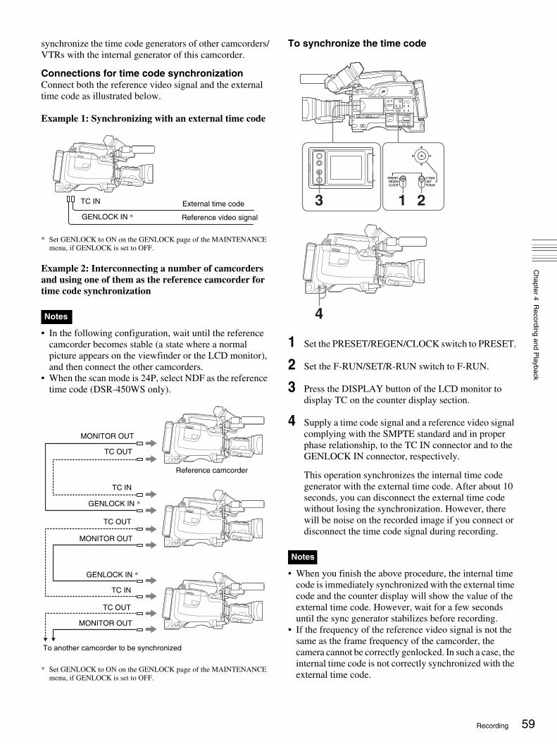
Chapter 4 R
ecording and Playback
synchronize the time code generators of other camcorders/VTRs with the internal generator of this camcorder.
Connections for time code synchronizationConnect both the reference video signal and the external time code as illustrated below.
Example 1: Synchronizing with an external time code
* Set GENLOCK to ON on the GENLOCK page of the MAINTENANCE menu, if GENLOCK is set to OFF.
Example 2: Interconnecting a number of camcorders and using one of them as the reference camcorder for time code synchronization
• In the following configuration, wait until the reference camcorder becomes stable (a state where a normal picture appears on the viewfinder or the LCD monitor), and then connect the other camcorders.
• When the scan mode is 24P, select NDF as the reference time code (DSR-450WS only).
* Set GENLOCK to ON on the GENLOCK page of the MAINTENANCE menu, if GENLOCK is set to OFF.
To synchronize the time code
1 Set the PRESET/REGEN/CLOCK switch to PRESET.
2 Set the F-RUN/SET/R-RUN switch to F-RUN.
3 Press the DISPLAY button of the LCD monitor to display TC on the counter display section.
4 Supply a time code signal and a reference video signal complying with the SMPTE standard and in proper phase relationship, to the TC IN connector and to the GENLOCK IN connector, respectively.
This operation synchronizes the internal time code generator with the external time code. After about 10 seconds, you can disconnect the external time code without losing the synchronization. However, there will be noise on the recorded image if you connect or disconnect the time code signal during recording.
• When you finish the above procedure, the internal time code is immediately synchronized with the external time code and the counter display will show the value of the external time code. However, wait for a few seconds until the sync generator stabilizes before recording.
• If the frequency of the reference video signal is not the same as the frame frequency of the camcorder, the camera cannot be correctly genlocked. In such a case, the internal time code is not correctly synchronized with the external time code.
Notes
GENLOCK IN *
External time codeTC IN
Reference video signal
Reference camcorder
To another camcorder to be synchronized
MONITOR OUT
TC OUT
MONITOR OUT
TC OUT
MONITOR OUT
TC OUT
GENLOCK IN *
TC IN
GENLOCK IN *
TC IN
Notes
PRESET
CLOCKREGEN
F-RUN
R-RUNSET
3
4
21
59Recording

60
Chapter 4 R
ecording and Playback
• When the GENLOCK item is set to OFF on the GENLOCK page of the MAINTENANCE menu, the time code cannot be synchronized with the reference video signal. In this case, set the GENLOCK item to ON.
About user bit settings during time code synchronizationWhen the time code is synchronized, only the time data is synchronized with the external time code value. Therefore, the user bits can have their own settings for each camcorder.
To release the time code synchronizationFirst disconnect the external time code, then set the F-RUN/SET/R-RUN switch to R-RUN.
To change the power supply from the battery pack to an external power supply during time code synchronizationTo maintain a continuous power supply, connect the external power supply to the DC IN connector before removing the battery pack. You may lose time code synchronization if you remove the battery pack first.
Camera synchronization during time code synchronizationDuring time code synchronization, the camera is genlocked to the reference video signal input from the GENLOCK IN connector.
Setting for special shooting cases
Depending on the shooting conditions, set the camcorder appropriately referring below.
To correct skin detailYou can specify a color other than a skin tone to adjust the color.
1 Set SKIN AREA IND to ON on the SKIN DETAIL page of the PAINT menu.
For details on menu operations, see “Basic menu operations” on page 93.
2 Set SKIN DETECT on the SKIN DETAIL page of the PAINT menu.
This causes the area detect cursor to be shown in the viewfinder.
3 Place the area detect cursor on the target, then execute SKIN DETECT.
This designates the correction area, which is indicated by a zebra pattern.
4 Change the value of SKIN DTL WIDTH (0 to 359) on the SKIN DETAIL page so that the zebra pattern may be displayed in the target area.
Set the correction level beforehand on the SKIN DETAIL LVL item on the SKIN DETAIL page.
5 When the setting is finished, set SKIN AREA IND to OFF on the SKIN DETAIL page.
Shooting conditions
Setting and effect
The subject is completely still (Example: When shooting documents, drawings, etc.).
Setting: Set the EVS (Enhanced Vertical definition System) function to ON on the SW STATUS page of the PAINT menu. Enabling the EVS function tends to increase the occurrence of aliasing problems (moiré patterns). Therefore, normally leave the function disabled.Effect: This enhances the vertical resolution.
When adjusting for skin detail or tone (Example: When shooting to hide skin details)
Setting: See “To correct skin detail” on page 60.Effect: This adjusts the skin detail or tone to a designated active area.
The 3200K preset white balance makes the picture reddish.
Setting: Change the setting of the preset white balance on the PRESET WHT page of the MAINTENANCE menu.Effect: This prevents the picture from reddening.
Recording

Chapter 4 R
ecording and Playback
Back Space Editing
This section describes the steps for recording several scenes continuously.
1 Follow steps in “Basic Procedure for Shooting” on page 46 to begin recording.
To continue the time code that has been recorded on the tape, set the F-RUN/SET/R-RUN switch to R-RUN.
For details of time codes, see “Setting the time data” on page 57.
2 When you have finished recording a scene, press the REC button on the camcorder or the VTR button on the lens.
This pauses the recording operation.
Do not do any of the following before the next scene is shot as it will interrupt the recording (the recording will not be continuous).• Remove the cassette.• Transport the tape (play, rewind, fast forward).• Replace the battery when the camcorder is powered.
3 When you are ready to shoot the next scene, again press the REC button on the camcorder or the VTR button on the lens.
This restarts the recording operation.
4 Repeat steps 2 and 3 for each scene to be shot.
If there is a long period before shooting the next sceneOnce put the camcorder into recording pause mode, it waits a certain (user-definable) period of time and then automatically switches to standby-off mode. When the
camcorder is in standby-off mode, it takes time for the recording to start after pressing the REC button.
You can set the time out value for automatic switching to standby-off mode from 1 minute, 3 minutes, or 5 minutes, on the VTR MODE page of the MAINTENANCE menu (page 84).
Starting back space editing at any tape position
This section describes the steps for inserting a new scene at any desired position on the tape.The following steps can also be used to restart recording after an interruption has occurred.
1 Insert the cassette containing the previous recording.
2 Perform steps 2 to 11 in “Basic Procedure for Shooting” on page 46.
To continue from the last time code of the previous recording, set the PRESET/REGEN/CLOCK switch to REGEN.
For details about time codes, see “Setting the time data” on page 57.
3 Press the PLAY button.
The recorded contents are displayed on the viewfinder screen.
Note
To Procedure
Restart an interrupted recording (see step 2 above)
See next section “Starting back space editing at any tape position” on page 61.
Check the recorded contents
See “Checking the recorded contents immediately after shooting — Recording Review” on page 65.
Stop recording Press the REC button on the camcorder or the VTR button on the lens, then press the STOP button.
Operation at playback
Procedure
Fast forward the tape
Press the F FWD button.
Rewind the tape Press the REW button.
EDIT STOPREV
REW PLAY F FWD
FWDSEARCH STOP button
REW button
F FWD button
PLAY button
61Back Space Editing

62
Chapter 4 R
ecording and Playback
4 Press the STOP button when the tape reaches the position where you want to start the new recording (see the figure in step 3).
This stops playback.
5 Press the RET button on the lens.
This rewinds the tape slightly and runs it until the continue point, then sets the camcorder to recording pause state.
6 Press the REC button on the camcorder or the VTR button on the lens.
This starts recording.
To carry out back space editing frame by frame, specify the continue position using the edit search function. For details, see the next section “Using the edit search function while back space editing”.
• When the scan mode is 24P, the value of the least significant digit is limited to 4 or 9 (DSR-450WS only).
• If you set the POWER switch to off during recording or when recording is paused, the camcorder automatically goes through its shut-down sequence, then powers off. When you next set the POWER switch to on, the camcorder automatically finds the point at which recording ended, and sets itself up so that you can carry in with continuous recording. Note that this operation takes several seconds: do not set the POWER switch to off or replace the battery during this interval, as the automatic recording continuity will be lost. Note also that the recording continuity is lost in the following cases.- If the POWER switch is set to on and off repeatedly.- If the camcorder is left powered off for several hours.- If the camcorder is subject to severe vibration while
powered off.- If for any other reason the automatic recording
continuity function is unable to operate correctly.- If the lithium battery (CR2032) is exhausted, or if no
lithium battery has been fitted.- If the recording format is changed.
Using the edit search function while back space editing
You can use the edit search function to find the desired tape location when continuing to record from any other location on the tape. Press and hold one of the EDIT SEARCH +FWD/–REV buttons to activate the search playback function for as long as you hold down it.
1 Insert the cassette containing the previous recording.
2 Perform steps 2 to 11 in “Basic Procedure for Shooting” on page 46.
3 Press and hold either of the +FWD or –REV button of the EDIT SEARCH +FWD/–REV buttons.
The tape is moved in reverse or forward search mode for as long as you hold down the button, and the image is shown in the viewfinder.
Do not shut off the power while using the edit search function. The continue point may be lost.
4 Release the +FWD or –REV button when you find the tape location where you want to continue shooting.
Recording is paused.
5 Press the REC button on the camcorder to the VTR button on the lens.
Recording starts.
Notes
Note
EDIT STOPREV
REW PLAY F FWD
FWDSEARCH
–REV button +FWD button
Back Space Editing

Chapter 4 R
ecording and Playback
Time-Lapse Video (Interval Rec)
Interval Rec mode is effective for shooting objects that move very slowly. As shown in the following figure, you need to set the recording time for one recording session (REC TIME) and the total time consisting of one recording session and the following interval (INTERVAL TIME).
A pre-lighting function is available. This function automatically turns on the light before recording starts, which allows you to record pictures under stable light and color temperature conditions.
Making settings before shooting
To record in Interval Rec mode, you need to set the related items beforehand as follows.
1 Set INTERVAL REC to ON on the FUNCTION 1 page of the OPERATION menu.
For details on menu operations, see “Basic menu operations” on page 93.
The camcorder is in Interval Rec mode. The TALLY indicator (green) in the viewfinder flashes (one flash/second) while the camcorder is in this mode.
2 Set INTERVAL TIME (total time consisting of one recording session and the following interval) on the FUNCTION 1 page of the OPERATION menu.
You can select either 30S, 1M, 5M, 10M, 30M, or 1H.Here S means seconds (30S is 30 seconds), M means minutes (5M is 5 minutes), and H means hours (1H is one hour).
3 Set REC TIME (recording time for one recording session) on the FUNCTION 1 page of the OPERATION menu.
You can select either 0.5S, 1.0S, 1.5S, 2.0S, 5S, 10S, 30S, 1M, 5M, or 10M.Here S means seconds (5S is 5 seconds) and M means minutes (1M is one minute).
4 To turn on the light automatically before starting to record, set PRE-LIGHTING (time to turn on the light before starting to record) on the FUNCTION 1 page of the OPERATION menu.
You can select either OFF, 2S, 5S, or 10S.
• Set the LIGHT switch on the camcorder to AUTO to turn on the light before recording. The light switch must also be set to ON. With these settings, the light turns on and off automatically. However, the light remains on continuously if the off time is less than 5 seconds.
• When the LIGHT switch is set to MAN and the light switch is set to ON, the light remains on continuously.
To end the menu operation, flick the MENU switch to OFF. The menu disappears from the screen and the message “INTERVAL” flashes along the bottom of the screen.You can check the setting of Interval Rec in the VTR STATUS window (page 102).
The camcorder exits Interval Rec mode whenever it is powered off. However, the settings of INTERVAL TIME, REC TIME, etc. are maintained. You do not need to set them again the next time you use Interval Rec mode.
Shooting and recording in Interval Rec mode
1 After performing the basic procedures for shooting and recording, following the instructions in “Making settings before shooting” on page 63, secure the camcorder so that it will not move.
2 Press the REC button on the camcorder or the VTR button on the lens.
Total time consisting of one recording session and the following interval (INTERVAL TIME)
Recording time for one recording session (REC TIME)
? 03 FUNCTION1 TOP
ASSIGN SW <1> : ATW
ASSIGN SW <2> : OFF
ASSIGN SW <3> : OFF
ASSIGN SW <4> : OFF
DF/NDF : DF
INTERVAL REC : ON
REC TIME : 0.5S
INTERVAL TIME : 30S
PRE-LIGHTING : OFF
Notes
Note
63Time-Lapse Video (Interval Rec)

64
Chapter 4 R
ecording and Playback
The camcorder starts recording in Interval Rec mode. When you use the pre-lighting function, recording starts after the light is switched on.While recording in Interval Rec mode, the TALLY indicator (green) in the viewfinder flashes (4 flashes/second) and the message “INTERVAL” appears on the viewfinder screen. While recording, the REC indicator in the viewfinder lights.
To interrupt interval recordingPress the REC button on the camcorder or the VTR button on the lens. The camcorder operates as explained below.
When the button is pressed during interval recordingRecording in Interval Rec mode stops. Press the REC or VTR button again to start recording in Interval Rec mode again.
When the button is pressed during a pause of interval recordingRecording in Interval Rec mode stops, and normal recording starts. Press the REC or VTR button again to interrupt recording. Press the REC or VTR button once again to start recording in Interval Rec mode.
To end auto interval recordingYou can exit Interval Rec mode by setting the POWER switch to OFF or setting INTERVAL REC to OFF on the FUNCTION 1 page of the OPERATION menu.
Notes on Auto Interval Rec mode
AudioAudio fade-in/fade-out functions are not carried out in Interval Rec mode.
Playback control buttonsWhile recording in Interval Rec mode, you cannot use the playback control buttons (EJECT, REW, F FWD, PLAY, and STOP). To use these buttons, stop recording by pressing the REC button on the camcorder or the VTR button on the lens.
Menu operationWhile recording in Interval Rec mode, you cannot change the settings of INTERVAL TIME and REC TIME. To change the settings, stop recording by pressing the REC button on the camcorder or the VTR button on the lens.
Recording Analog Composite Signals (with a CBK-SC01 Installed- DSR-450WS/450WSP only)
Installing a CBK-SC01 Composite Input Board in the camcorder enables you to record analog composite signals from external equipment connected to the GENLOCK IN connector.
1 Set REC VIDEO SOURCE to EXT on the SOURCE SEL page of the OPERATION menu.
For details on menu operations, see “Basic menu operations” on page 93.
2 Input analog composite signals to the GENLOCK IN connector of the camcorder.
These signals are displayed on the viewfinder and the LCD monitor, and can be recorded on the tape.
Even when the GENLOCK item is set to OFF on the GENLOCK page of the MAINTENANCE menu, the camcorder is automatically synchronized with the external reference video signal when the external video signal is input to the GENLOCK IN connector in EXT mode. When the setting is switched to CAM mode, or when no signals are input even in EXT mode, the camcorder is reset to the original setting.
To use setup remove (DSR-450WS only)Setup remove is a function that removes a setup that has been added to a video signal when recording. The factory setting of setup remove is ON.In order to set the setup remove function off, select OFF in SETUP REMOVE on the SOURCE SEL page of the OPERATION menu.
Note
19 SOURCE SEL TOP
REC VIDEO SOURCE: EXT
SETUP REMOVE :ON
Recording Analog Composite Signals (with a CBK-SC01 Installed- DSR-450WS/450WSP only)

Chapter 4 R
ecording and Playback
Playing and Checking Recorded Contents
By pressing the PLAY button, you can review any length of recording on the viewfinder screen in black and white or in color on the LCD monitor. There are two other ways to review the recording.• Recording review: You can view the last two to ten
seconds of the recording on the viewfinder screen in black and white or in color on the LCD monitor.
• Playback in external color video monitor: You can see the recording in color on a color video monitor without the need for any external adaptor.
For details about the switches and controls used to select the audio output signal and to adjust the audio level, see “Location and Function of Parts” on page 9.
Checking the recorded contents immediately after shooting — Recording Review
With recording paused, press the RET button on the lens. The tape is automatically rewound over the last approximately 2 seconds of the recording (approximately 10 seconds maximum if you press and hold the RET button), and then this last part of the recording is shown in the viewfinder and on the LCD monitor. Use this function to check whether recording went correctly.By assigning the LENS RET function to the ASSIGN switch, you can use the switch in the same way as the lens RET button.
For details, see “Assigning functions to ASSIGN switches” on page 106.
• During recording review, do not set the POWER switch to off. The camcorder may not be able to find the continue point.
• You cannot start recording until the recording review has finished.
Checking the recording on the color video monitor
Connect a color video monitor to the MONITOR OUT connector or the VIDEO OUT connector of the camcorder. By pressing the PLAY button, you can view the recorded picture.
For details about how to connect a monitor, see “Connecting a Monitor” on page 40.
For the DSR-450WS/450WSP, only the picture displayed through the camera is output to the CBK-SD01 SDI Output Board. Playback pictures cannot be output even during playback.
To use setup add (DSR-400/450WS only)Setup add is a function that adds a setup to the playback video signal. To activate this function, set SETUP ADD to ON on the VTR MODE page of the MAINTENANCE menu.
• The video image that connects the DVCAM format and DV format is distorted during playback.
• The camcorder can play video and audio that is recorded in DVCAM format or DV format (in SP mode).
• If two or more audio sampling frequencies are mixed on one tape, the part where the video images are recorded in different frequencies will be distorted.
Notes
Note
Notes
65Playing and Checking Recorded Contents

hapter
66
Chapter 5 M
enu Displays and D
etailed Settings
CMenu Displays and Detailed Settings
Menu Organization and Operation
The following shows the organization of menus in this camcorder.
The USER menu consisting of items and pages registered at the factory is used. The number in parenthesis is the page number that setting is displayed on.
For details about USER MENU CUSTOMIZE, see “Editing the USER menu” on page 95.
1) Only for the DSR-450WS/450WSP2) Only when a CBK-SC01 Composite Input Board is installed in the DSR-
450WS/450WSP3) Only when a CBK-SD01 SDI Output Board is installed in the DSR-
450WS/450WSP
TOP MENU USER Page 1
Page 2
Page 3
Page 4
Page 5
Page 6
Page 7
IRIS OVERRIDEDETAIL LEVELMASTER BLACKBLACK GAMMAMASTER BLK GAMMACOLOR TEMP <P>
SKIN DETAIL ALL SKIN DETECTSKIN AREA INDSKIN DTL SELECTSKIN DETAIL SKIN DETAIL LVL
SCN 1 SCN 2 SCN 3 SCN 4 SCN 5 STANDARD
REC FORMAT AU MODE 16:9/4:3 SELECT 1)
SCAN MODE 1)
REC VIDEO SOURCE 2)
REAR BNC OUT SEL 3)
GL H PHASE GL SC PHASE GL SC 0/180 SEL
MARKER CENTER SAFETY ZONE
ASSIGN SW <1> ASSIGN SW <2> ASSIGN SW <3> ASSIGN SW <4>
Menu selection 1st hierarchy 2nd hierarchy 3rd hierarchy
(Continued) (Continued)
(78)
(81)
(82)(80)
(81)(86)
(82)(82)
(82)(82)
(82)(82)
(84)(84)(84)(84)(84)
(84)
(86)(86)
(79)(79)
(79)(75)
(88)(88)
(88)
(77)(77)
(77)
(76)(76)(76)(76)
Menu Organization and Operation

Chapter 5 M
enu Displays and D
etailed Settings
1) Only for the DSR-450WS/450WSP2) Only when a CBK-SD01 SDI Output Board is installed in the DSR-
450WS/450WSP3) Only for the DSR-400/450WS
Page 8
OUTPUT
MONITOR OUT
FUNCTION 1
FUNCTION 2
VF DISP 1
VF DISP 2
MARKER 1
USER MENU CUSTOMIZE
ALL
OPERATION
CLOCK ADJUST HOUR MIN SECYEARMONTHDAY
LCD BRIGHT <L>LCD BRIGHT <H>LCD COLORREAR BNC OUT SEL 2)
MONI OUT VFDISPMONI OUT MENUMONI OUT TCMONI OUT MARKERMONI OUT ZEBRA
ASSIGN SW <1>ASSIGN SW <2>ASSIGN SW <3>ASSIGN SW <4>DF/NDF 3)
INTERVAL RECREC TIMEINTERVAL TIMEPRE-LIGHTING
D5600WIDE AWBWHITE SWITCH <B>SHOCKLESS WHITEATW SPEEDLOW LIGHTLOW LIGHT LEVELVF BATT WARNING
VF DISPVF DISP MODEDISP EXTENDERDISP FILTERDISP WHITEDISP GAINDISP SHUTTERDISP AUDIODISP TAPEDISP IRIS
DISP COLOR TEMPDISP BATT REMAINDISP DC INDISP 16:9/4:3 ID 1)
DISP VTR STATUSDISP VTR TRIGGERDISP TIME CODEDISP REC FORMAT
MARKERCENTERSAFETY ZONESAFETY AREAASPECT 1)
ASPECT SELECT 1)
ASPECT MASK(4:3) 1)
ASPECT MASK LVL 1)
100%MARKER
(Continued)
Menu selection 1st hierarchy 2nd hierarchy 3rd hierarchy
(Continued)
(91)(91)
(91)(91)(91)
(91)(91)
67Menu Organization and Operation
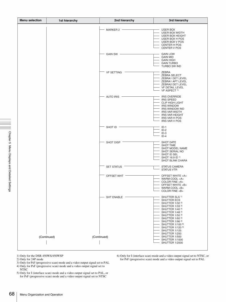
68
Chapter 5 M
enu Displays and D
etailed Settings
1) Only for the DSR-450WS/450WSP2) Only for 24P mode3) Only for PsF (progressive scan) mode and a video output signal set to PAL4) Only for PsF (progressive scan) mode and a video output signal set to
NTSC5) Only for I (interlace scan) mode and a video output signal set to PAL, or
for PsF (progressive scan) mode and a video output signal set to NTSC
6) Only for I (interlace scan) mode and a video output signal set to NTSC, or for PsF (progressive scan) mode and a video output signal set to PAL
MARKER 2
GAIN SW
VF SETTING
AUTO IRIS
SHOT ID
SHOT DISP
SET STATUS
OFFSET WHT
SHT ENABLE
USER BOXUSER BOX WIDTHUSER BOX HEIGHTUSER BOX H POSUSER BOX V POSCENTER H POSCENTER V POS
GAIN LOWGAIN MIDGAIN HIGHGAIN TURBOTURBO SW IND
ZEBRAZEBRA SELECTZEBRA1 DET LEVELZEBRA1 APT LEVELZEBRA2 DET LEVELVF DETAIL LEVELVF ASPECT 1)
IRIS OVERRIDEIRIS SPEEDCLIP HIGH LIGHTIRIS WINDOWIRIS WINDOW INDIRIS VAR WIDTHIRIS VAR HEIGHTIRIS VAR H POSIRIS VAR V POS
ID-1ID-2ID-3ID-4
SHOT DATESHOT TIMESHOT MODEL NAMESHOT SERIAL NOSHOT ID SELSHOT 16:9 ID 1)
SHOT BLINK CHARA
STATUS CAMERASTATUS VTR
OFFSET WHITE <A>WARM-COOL <A>COLOR FINE <A>OFFSET WHITE <B>WARM-COOL <B>COLOR FINE <B>
SHUTTER SLS 1)
SHUTTER ECSSHUTTER 1/32 2)
SHUTTER 1/33 3)
SHUTTER 1/40 4)
SHUTTER 1/48 2)
SHUTTER 1/50 3)
SHUTTER 1/60 5)
SHUTTER 1/96 2)
SHUTTER 1/100 6)
SHUTTER 1/120 4)
SHUTTER 1/125SHUTTER 1/250SHUTTER 1/500SHUTTER 1/1000SHUTTER 1/2000
(Continued)
Menu selection 1st hierarchy 2nd hierarchy 3rd hierarchy
(Continued)
Menu Organization and Operation

Chapter 5 M
enu Displays and D
etailed Settings
1) Only for the DSR-450WS/450WSP2) Only for the DSR-450WS3) Only when a CBK-SC01 Composite Input Board is installed in the DSR-
450WS/450WSP
LENS FILE
FORMAT
SOURCE SEL 3)
SW STATUS
WHITE
BLACK/FLARE
GAMMA
BLACK GAMMA
KNEE
DETAIL 1
LENS FILE SELECTF.ID
16:9/4:3 SELECT 1)
WIDE ID 1)
SCAN MODE 1)
REC VIDEO SOURCESETUP REMOVE 2)
GAMMACHROMAMATRIXKNEEWHITE CLIPDETAILAPERTUREFLAREEVSTEST SAW
COLOR TEMP <A>COLOR FINE <A>R GAIN <A>B GAIN <A>D5600K <A>COLOR TEMP <B>COLOR FINE <B>R GAIN <B>B GAIN <B>D5600K <B>
MASTER BLACK R BLACK B BLACK MASTER FLARER FLARE G FLARE B FLARE FLARE
GAMMASTEP GAMMAMASTER GAMMAR GAMMAG GAMMAB GAMMAGAMMA SELECT 1)
GAMMA SEL(STD)GAMMA SEL(FILM)1)
BLACK GAMMABLK GAM RANGEMASTER BLK GAMMAR BLACK GAMMAG BLACK GAMMAB BLACK GAMMA
KNEEKNEE POINT KNEE SLOPE KNEE SATURATIONKNEE SAT LEVELWHITE CLIPWHITE CLIP LEVEL
DETAILAPERTUREDETAIL LEVELAPERTURE LEVELDTL H/V RATIOCRISPENINGLEVEL DEPENDLEVEL DEPEND LVLDETAIL FREQUENCY
PAINT
(Continued)
Menu selection 1st hierarchy 2nd hierarchy 3rd hierarchy
(Continued)
69Menu Organization and Operation

70
Chapter 5 M
enu Displays and D
etailed Settings
DETAIL 2
DETAIL 3
SKIN DETAIL
MTX LINEAR
MTX MULTI
V MODULATION
LOW KEY SAT
SCENE FILE
WHITE SHADING
KNEE APERTUREKNEE APT LVLDETAIL COMBCROSS COLORCROSS COLOR LVLDETAIL LIMITDTL WHT LMTDTL BLK LMTDTL V-BLK LMT
FINE DTL FINE DTL LVLV DTL CREATIONH/V CONTROL MODE
SKIN DETAIL ALLSKIN DETECTSKIN AREA INDSKIN DTL SELECTSKIN DETAILSKIN DETAIL LVLSKIN DTL SATSKIN DTL HUESKIN DTL WIDTH
MATRIXMATRIX(USER)MATRIX(PRESET)MATRIX R-GMATRIX R-BMATRIX G-RMATRIX G-BMATRIX B-RMATRIX B-G
MATRIXMATRIX(MULTI)MATRIX AREA INDMATRIX COLOR DETMTX(MULTI)AXISMTX(MULTI)HUEMTX(MULTI)SAT
VMODMASTER VMODR VMODG VMODB VMOD
LOW KEY SATL.KEY SAT LEVELL.KEY SAT RANGEY BLACK GAMMAY BLK GAM LEVELY BLK GAM RANGE
1 2 3 4 5 STANDARDSCENE RECALLSCENE STOREF. ID
WHT SHAD CH SELR/G/B WHT H SAWR/G/B WHT H PARAR/G/B WHT V SAW R/G/B WHT V PARAWHITE SAW/PARA
MAINTENANCE
(Continued)
Menu selection 1st hierarchy 2nd hierarchy 3rd hierarchy
(Continued)
Menu Organization and Operation

Chapter 5 M
enu Displays and D
etailed Settings
1) Only for the DSR-400/450WS2) Only for the DSR-450WS/450WSP
BLACK SHADING
BATTERY
AUDIO
VTR MODE
PRESET WHT
DCC ADJUST
AUTO IRIS 2
FUNCTION 3
GENLOCK
ND COMP
AUTO SHADING
BLK SHAD CH SELR/G/B BLK H SAWR/G/B BLK H PARAR/G/B BLK V SAWR/G/B BLK V PARABLACK SAW/PARAMASTER BLACKMASTER GAIN(TMP)
<Sony Info> BEFORE END 1 END1<Sony> BEFORE END 2 END 2<Others, EXT DC> BEFORE END 3 END 3
AU MODEAU HEADROOMAU FADEAU SG(1KHz)F AUDIO VOL
REC TALLY BLINKSTBY OFF TIMERREC FORMATSETUP ADD 1)
COLOR TEMP <P>COLOR FINE <P>R GAIN <P>B GAIN <P>D5600K <P>AWB ENABLE <P>
DCC FUNCTION SELDCC D RANGEDCC POINTDCC GAINDCC DELAY TIME
IRIS WINDOW IRIS WINDOW INDIRIS LEVELIRIS APL RATIOIRIS VAR WIDTHIRIS VAR HEIGHTIRIS VAR H POSIRIS VAR V POSIRIS SPEEDCLIP HIGH LIGHT
WHT FILTER INHCOLOR BAR SELREC TALLYUSER & ALL ONLYRM COMMON MEMORY 2)
RM REC START 2)
i.LINK CTL
GENLOCKGL H PHASEGL SC PHASEGL SC 0/180 SEL
ND OFFSET ADJUSTCLEAR ND OFFSET
AUTO BLK SHADINGRESET BLK SHDMASTER GAIN(TMP)(Continued)
Menu selection 1st hierarchy 2nd hierarchy 3rd hierarchy
71Menu Organization and Operation

72
Chapter 5 M
enu Displays and D
etailed Settings
USER FILE
USER FILE 2
ALL FILE
SCENE FILE
REFERENCE
LENS FILE 1
LENS FILE 2
LENS FILE 3
MEMORY STICK
USER FILE LOADUSER FILE SAVEF. IDUSER PRESET
STORE USR PRESETCLEAR USR PRESETCUSTOMIZE RESETLOAD CUSTOM DATALOAD OUT OF USERBEFORE FILE PAGEUSER LOAD WHITE
ALL FILE LOADALL FILE SAVEF. IDALL PRESETSTORE ALL PRESETCLEAR ALL PRESET
1 2 3 4 5 STANDARDSCENE RECALLSCENE STOREF. ID
REFERENCE STOREREFERENCE CLEARREFERENCE LOADREFERENCE SAVEF. IDSCENE WHITE DATA
LENS FILE RECALLLENS FILE STOREF. IDLENS NO OFFSETSOURCE IRIS GAIN
LENS M VMODLENS CENTER HLENS CENTER VLENS R FLARELENS G FLARELENS B FLARELENS W-R OFSTLENS W-B OFST
SHADING CH SELLENS R/G/B H SAWLENS R/G/B H PARALENS R/G/B V SAWLENS R/G/B V PARA
M.S. FORMATM.S. IN > JUMP TO
FILE
(Continued)
Menu selection 1st hierarchy 2nd hierarchy 3rd hierarchy
Menu Organization and Operation

Chapter 5 M
enu Displays and D
etailed Settings
1) Only for the DSR-450WS/450WSP
The TOP menu
The TOP menu consists of the following submenus.
When you select an item in the TOP menu, this displays the most recently shown page of the corresponding submenu. When the submenu is selected for the first time, the CONTENTS page appears.
The USER menuThis menu allows you to add items from the OPERATION, PAINT, MAINTENANCE, FILE, and DIAGNOSIS menus to suit your needs. By gathering frequently used items on the USER menu beforehand, you can call up them quickly whenever you need them.Usually by flicking the MENU switch to ON, the USER menu is displayed.
The USER MENU CUSTOMIZE menuThis menu allows you to add pages to or delete pages from the USER menu to suit your needs.
The ALL menuThis menu contains all items of the OPERATION, PAINT, MAINTENANCE, FILE, and DIAGNOSIS menus as they are in one menu.
DIAGNOSIS HOURS METER
TIME/DATE
DEV STATUS 1
DEV STATUS 2
OPTION BOARD 1)
RESET METERDRUM RUNNINGTAPE RUNNINGOPERATIONTHREADINGDRUM RUNNING-2TAPE RUNNING-2OPERATION-2THREADING-2
CLOCK ADJUSTHOURMINSECYEARMONTHDAY
I/OFP1FP2CNFRAMATEEPROMDCP1DCP2PALSIPXBCSSCISYRM 1)
AUTO CHECKHUMID TIMER RESET
SDI OUTPUTCOMPOSITE VIDEO INPUT
Menu selection 1st hierarchy 2nd hierarchy 3rd hierarchy
<TOP MENU>
USER
USER MENU CUSTOMIZE
ALL
OPERATION
PAINT
MAINTENANCE
FILE
DIAGNOSIS
73Menu Organization and Operation
74
Chapter 5 M
enu Displays and D
etailed Settings
The OPERATION menuThis menu contains items for changing settings according to conditions related to the subject when the camcorder is being operated.
The PAINT menuThis menu contains items for making detailed image adjustments while using a waveform monitor to monitor the waveforms output by the camera. Support of a video engineer is usually required to use this menu. Although you can also use an external remote control unit to set the items on this menu, this menu is effective when using the camcorder by itself outdoors.
The MAINTENANCE menuThis menu contains items for performing camera maintenance operations, such as changing the VTR system or using infrequently used paint items.
The FILE menuThis menu is for saving the adjusted data in the camcorder memory or in a “Memory Stick”. The following files can be saved.
The user fileIn the user file, the setting items and setting data of the customized USER menu are saved. Once you save the user file in a “Memory Stick”, you can easily set the USER menu to your preference by loading the data from the “Memory Stick”.
For details on the user file, see “Saving and Loading User Files” on page 109.
The ALL fileIn the ALL file, the setting data of all of the menus are saved. Once a camcorder is set according to your preferences and you save its ALL file in a “Memory Stick”, you can easily set other camcorders to the settings of the camcorder that you already set by loading the data from the “Memory Stick”.
Items included in the ALL file are marked with an “A” in the “File” column on the menu list.
The preset fileIn the preset file, the preset values of setting items in the menu are saved. You can save the preset file in the built-in memory of the camcorder.
Items included in the preset file are marked with a “P” in the “File” column on the menu list.
The scene fileIn the scene file, the setting values of event items adjusted to shoot a particular scene are saved. You can save up to five scene files in the camcorder memory and up to 100 scene files in a “Memory Stick”. For example, first adjust the settings to shoot a particular scene at the rehearsal and then save them as a scene file. Then load this file before the actual shooting so that you can quickly recreate setup conditions that are the same as those in rehearsal.
Items included in the scene file are marked with an “Sc” in the “File” column on the menu list.
The reference fileIn the reference file, the reference setting values used when executing SCENE FILE STANDARD (page 116) are saved. You can save one reference file in a “Memory Stick”. If the reference file is not saved, the factory default values are used as reference values.
Items included in the reference file are marked with an “R” in the “File” column on the menu list.
The lens fileIn the lens file, the setting data used to compensate for the characteristics of lenses, such as flare, white shading, auto iris gain, center marker position, and compensation value of extender white, is saved. You can save up to 16 lens files in the camcorder memory and up to 100 lens files in a “Memory Stick”.
Items included in the lens file are marked with an “L” in the “File” column on the menu list.
The DIAGNOSIS menuThis menu enables you to confirm the VTR status or identify a failed circuit board.
Menu Organization and Operation

Chapter 5 M
enu Displays and D
etailed Settings
Menu list
The pages of the menu that have been registered in the USER menu at the factory are indicated by the page (Page1 to 8) in the “USER menu” column. The USER MENU CUSTOMIZE menu allows you to add and delete pages in the USER menu to suit your requirements.
When the setting range in the “Settings” column is surrounded by parentheses ( ), the setup value is a relative
value. The setting range shown on the menu screen may differ from what is shown in the manual.
The “File” columnThe letters in the “File” column stand for the following.A: Items saved in the ALL fileP: Items saved in the preset fileSc: Items saved in the scene fileR: Items saved in the reference fileL: Items saved in the lens fileSt: Items changed in value by the STANDARD operation
The OPERATION menu
Note
Page Item Settings Default USER menu
Description File
OUTPUT LCD BRIGHT <L> –32 to 31 0 – Adjusts brightness of the LCD monitor when the LCD button is set to L.
A P
LCD BRIGHT <H> Adjusts brightness of the LCD monitor when the LCD button is set to H.
LCD COLOR Adjusts the color strength of the LCD monitor.
REAR BNC OUT SEL(when option board is installed)
VBS/SDI VBS Page4 See “Selecting the output signals (DSR-450WS/450WSP only)” on page 104.
MONITOR OUT
MONI OUT VFDISP OFF/ON ON – Selects whether or not the VF DISP display signal is mixed to the output signal from the MONITOR OUT connector.
A P
MONI OUT MENU Selects whether or not the MENU display signal is mixed to the output signal from the MONITOR OUT connector.
MONI OUT TC OFF Selects whether or not the time code is mixed to the output signal from the MONITOR OUT connector.
MONI OUT MARKER Selects whether or not the marker signal is mixed to the output signal from the MONITOR OUT connector.
MONI OUT ZEBRA Selects whether or not the ZEBRA display signal is mixed to the output signal from the MONITOR OUT connector.
75Menu Organization and Operation

76
Chapter 5 M
enu Displays and D
etailed Settings
FUNCTION 1 ASSIGN SW <1> OFF/MARKER/ATW/LENS RET/REC SWITCH/TURBO SWITCH
ATW Page7 See “Assigning functions to ASSIGN switches” on page 106.
A P
ASSIGN SW <2> OFF
ASSIGN SW <3>
ASSIGN SW <4>
DF/NDF DF/NDF DF – Switches between drop frame (DF) mode and non-drop frame (NDF) mode.
INTERVAL REC OFF/ON OFF See “Time-Lapse Video (Interval Rec)” on page 63.REC TIME 0.5S/1.0S/
1.5S/2.0S/5S/10S/30S/1M/5M/10M
0.5S
INTERVAL TIME 30S/1M/5M/10M/30M/1H
1H
PRE–LIGHTING OFF/2SEC/5SEC/10SEC
OFF
FUNCTION 2 D5600 OFF/ON OFF – Turns on and off the function which electrically applies a 5600K color temperature filter (effective only when WIDE AWB is set to OFF).
A P Sc St
WIDE AWB OFF/ON ON Turns on and off the function which widens the range adjustable by Auto White Balance.
A P
WHITE SWTCH <B> MEM/ATW MEM Sets the function of the WHITE BAL switch when it is set to B.
SHOCKLESS WHITE
OFF/1/2/3 1 Changes the white gain smoothly when operating the WHITE BAL switch.
ATW SPEED 1/2/3/4/5 4 Sets the convergence speed for Auto Tracing White balance.
LOW LIGHT OFF/ON OFF Turns the warning display on or off when the video average level is less than the preset value.
LOW LIGHT LEVEL (–99 to 99) 0 Sets the level at which the LOW LIGHT function becomes effective.
VF BATT WARNING 10% / 20% 10% Sets the threshold value of remaining battery capacity to make the remaining capacity indication flash on the viewfinder screen.
VF DISP 1 VF DISP OFF/ON Depends on the switch
– See “Selecting the display items” on page 98.
–
VF DISP MODE 1/2/3 3 A P
DISP EXTENDER OFF/ON ON
DISP FILTER
DISP WHITE
DISP GAIN
DISP SHUTTER
DISP AUDIO
DISP TAPE
DISP IRIS
Page Item Settings Default USER menu
Description File
Menu Organization and Operation

Chapter 5 M
enu Displays and D
etailed Settings
VF DISP 2 DISP COLOR TEMP OFF/ON OFF – See “Selecting the display items” on page 98.
A P
DISP BATT REMAIN AUTO/VOLT/INT
INT
DISP DC IN OFF/ON OFF
DISP 16:9/4:3 ID
DISP VTR STATUS OFF/ON ON
DISP VTR TRIGGER
DISP TIME CODE OFF/ON OFF
DISP REC FORMAT
MARKER 1 MARKER OFF/ON OFF Page6 See “Setting the marker display” on page 100.
A P
CENTER
SAFETY ZONE
SAFETY AREA 80% / 90% / 92% / 95%
90% –
ASPECT OFF/ON OFF
ASPECT SELECT 4:3/13:9/14:9 4:3
ASPECT MASK (4:3) OFF/ON OFF
ASPECT MASK LVL 1/2, 1/4, 1/8 1/4
100% MARKER OFF/ON OFF
MARKER 2 USER BOX OFF/ON OFF – Turns the box cursor on or off. A P
USER BOX WIDTH 1 to 465 245 Width (from the center to right or left side)
USER BOX HEIGHT NTSC: 1 to 120 PAL: 1 to 142
72 Height (from the center to top or bottom)
USER BOX H POS –461 to 461 0 Horizontal position of the center
USER BOX V POS NTSC: –119 to 118PAL: –141 to 140
0 Vertical position of the center
CENTER H POS –48 to 47 0 Horizontal position of the center marker
CENTER V POS –15 to 14 0 Vertical position of the center marker
GAIN SW GAIN LOW –3dB/0dB/3dB/6dB/9dB/12dB/18dB/24dB/30dB/36dB
0dB – See “Setting gain values for the GAIN switch positions” on page 103.
A P
GAIN MID 9dB
GAIN HIGH 18dB
GAIN TURBO 36dB
TURBO SW IND OFF/ON OFF
VF SETTING ZEBRA OFF/ON OFF – See “Setting the viewfinder” on page 100.
A P
ZEBRA SELECT 1/2/BOTH 1
ZEBRA1 DET LVL 20% to 107% (in 1% steps)
70%
ZEBRA1 APT LVL 1% to 10% (in 1% steps)
10%
ZEBRA2 DET LVL 52% to 109% (in 1% steps)
100%
VF DETAIL LEVEL (–99 to 99) 0
VF ASPECT AUTO/16:9 AUTO
Page Item Settings Default USER menu
Description File
77Menu Organization and Operation
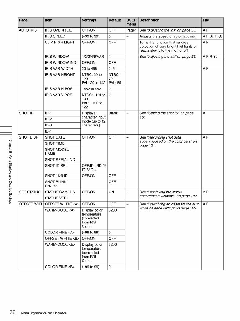
78
Chapter 5 M
enu Displays and D
etailed Settings
AUTO IRIS IRIS OVERRIDE OFF/ON OFF Page1 See “Adjusting the iris” on page 55. A P
IRIS SPEED (–99 to 99) 0 – Adjusts the speed of automatic iris. A P Sc R St
CLIP HIGH LIGHT OFF/ON OFF Turns the function that ignores detection of very bright highlights or reacts slowly to them on or off.
A P
IRIS WINDOW 1/2/3/4/5/VAR 1 See “Adjusting the iris” on page 55. A P R St
IRIS WINDOW IND OFF/ON OFF –
IRIS VAR WIDTH 20 to 465 245 A P
IRIS VAR HEIGHT NTSC: 20 to 120PAL: 20 to 142
NTSC: 72PAL: 85
IRIS VAR H POS –452 to 452 0
IRIS VAR V POS NTSC: –101 to 100PAL: –122 to 122
0
SHOT ID ID-1 Displays character input mode (up to 12 characters).
Blank – See “Setting the shot ID” on page 101.
A
ID-2
ID-3
ID-4
SHOT DISP SHOT DATE OFF/ON OFF – See “Recording shot data superimposed on the color bars” on page 101.
A P
SHOT TIME
SHOT MODEL NAME
SHOT SERIAL NO
SHOT ID SEL OFF/ID-1/ID-2/ID-3/ID-4
SHOT 16:9 ID OFF/ON OFF
SHOT BLINK CHARA
OFF
SET STATUS STATUS CAMERA OFF/ON ON – See “Displaying the status confirmation windows” on page 102.
A P
STATUS VTR
OFFSET WHT OFFSET WHITE <A> OFF/ON OFF – See “Specifying an offset for the auto white balance setting” on page 105.
A P
WARM-COOL <A> Display color temperature (converted from R/B Gain).
3200
COLOR FINE <A> (–99 to 99) 0
OFFSET WHITE <B> OFF/ON OFF
WARM-COOL <B> Display color temperature (converted from R/B Gain).
3200
COLOR FINE <B> (–99 to 99) 0
Page Item Settings Default USER menu
Description File
Menu Organization and Operation

Chapter 5 M
enu Displays and D
etailed Settings
SHT ENABLE SHUTTER SLS OFF/ON ON – See “To select the shutter mode and shutter speed” on page 53.The items which can be set differ depending on the CCD scan mode setting (page 108).
A P
SHUTTER ECS
SHUTTER 1/32
SHUTTER 1/33
SHUTTER 1/40
SHUTTER 1/48
SHUTTER 1/50
SHUTTER 1/60
SHUTTER 1/96
SHUTTER 1/100
SHUTTER 1/120
SHUTTER 1/125
SHUTTER 1/250
SHUTTER 1/500
SHUTTER 1/1000
SHUTTER 1/2000
LENS FILE LENS FILE SELECT 1 to 17 (17 only when serial lens connected)
1 – See “Selecting the lens file” on page 106.
–
F.ID Displays file name.
Blank L
FORMAT 16:9/4:3 SELECT 16:9 / 4:3 16:9 Page4 See “Selecting the aspect ratio (DSR-450WS/450WSP only)” on page 107.
A P
WIDE ID OFF/ON ON – Selects whether to add wide aspect identifying signal to video signal in 16:9 mode.
SCAN MODE NTSC: I/PsF/24PPAL: I/PsF
I Page4 See “Setting the CCD scan mode (DSR-450WS/450WSP only)” on page 108.
A P Sc R St
SOURCE SEL REC VIDEO SOURCE
CAM/EXT CAM Page4 See “Recording Analog Composite Signals (with a CBK-SC01 Installed- DSR-450WS/450WSP only)” on page 64.
A P
SETUP REMOVE (Only for the DSR-450WS)
OFF/ON ON –
Page Item Settings Default USER menu
Description File
79Menu Organization and Operation

80
Chapter 5 M
enu Displays and D
etailed Settings
The PAINT menu
Page Item Settings Default USER menu
Description File
SW STATUS GAMMA OFF/ON ON – Turns the gamma correction on or off. A P Sc St
CHROMA Turns the chroma of the composite signal on or off.
MATRIX Turns the linear matrix correction on or off.
A P Sc R St
KNEE Turns the knee correction on or off.
WHITE CLIP Turns the white clipping correction on or off.
A P Sc St
DETAIL Turns the detail signal on or off.
APERTURE Turns the aperture function on or off.
FLARE Turns the flare function on or off.
EVS OFF Turns the EVS shutter on or off. A P Sc R St
TEST SAW OFF/SAW/REC
OFF Selects the test signal. A P St
WHITE COLOR TEMP <A> Display color temperature (converted from R/B gain).
3200 – Sets the color temperature of WHITE A.
A P Sc St
COLOR FINE <A> (–99 to 99) 0 Adjusts the value more precisely when the color temperature adjustment through COLOR TEMP is not satisfactory.
R GAIN <A> Only the value of R GAIN is changed.
B GAIN <A> Only the value of B GAIN is changed.
D5600K <A> OFF/ON OFF Turns the WHITE A electronic 5600K filter on or off.
COLOR TEMP <B> Display color temperature (converted from R/B gain).
3200 Sets the color temperature of WHITE B.
COLOR FINE <B> (–99 to 99) 0 Adjusts the value more precisely when the color temperature adjustment through COLOR TEMP is not satisfactory.
R GAIN <B> Only the value of R GAIN is changed.
B GAIN <B> Only the value of B GAIN is changed.
D5600K <B> OFF/ON OFF Turns the WHITE B electronic 5600K filter on or off.
BLACK/FLARE
MASTER BLACK (–99 to 99) 0 Page1 Adjusts the black level of the master. A P Sc R St
R BLACK – Adjusts the R black level. A P Sc St
B BLACK Adjusts the B black level.
MASTER FLARE Adjusts the flare level of the master. A P Sc R St
R FLARE Adjusts the R flare level.
G FLARE Adjusts the G flare level.
B FLARE Adjusts the B flare level.
FLARE OFF/ON ON Turns the flare correction circuit on or off.
A P Sc St
Menu Organization and Operation

Chapter 5 M
enu Displays and D
etailed Settings
GAMMA GAMMA OFF/ON ON – Turns the gamma correction function on or off.
A P Sc St
STEP GAMMA 0.35 to 0.90 (in 0.05 steps)
0.45 Sets the master gamma correction curve in steps.
A P Sc R St
MASTER GAMMA (–99 to 99) 0 Sets the master gamma correction curve.
R GAMMA Sets the R gamma correction curve.
G GAMMA Sets the G gamma correction curve.
B GAMMA Sets the B gamma correction curve.
GAMMA SELECT STD/FILM STD Selects the gamma table.
GAM SEL (STD) 1 to 6 3 Selects the gamma table of STD.
GAM SEL (FILM) 1 to 5 1 Selects the gamma table of FILM.
BLACK GAMMA
BLACK GAMMA OFF/ON ON Page1 Turns the black gamma correction on or off.
A P Sc R St
BLK GAMMA RANGE
LOW/L.MID/H.MID/HIGH
HIGH – Sets the range affected by black gamma.
MASTER BLK GAMMA
(–99 to 99) 0 Page1 Adjusts the black gamma of the master.
R BLACK GAMMA – Sets the correction curve of the R black gamma.
G BLACK GAMMA Sets the correction curve of the G black gamma.
B BLACK GAMMA Sets the correction curve of the B black gamma.
KNEE KNEE OFF/ON ON – Turns the knee correction circuit on or off.
A P Sc R St
KNEE POINT 50.0 to 109.0 (in 0.1 steps)
100.0 Sets the knee point level.
KNEE SLOPE (–99 to 99) 0 Set the knee slope level.
KNEE SATURATION OFF/ON ON Turns the knee saturation function on or off.
KNEE SAT LEVEL (–99 to 99) 0 Sets the knee saturation level.
WHITE CLIP OFF/ON ON Turns the white clipping function on or off.
A P Sc St
WHITE CLIP LEVEL 100.0 to 109.5 (in 0.1 steps)
NTSC: 109.0 PAL: 105.0
Adjusts the white clipping level. A P Sc R St
Page Item Settings Default USER menu
Description File
81Menu Organization and Operation

82
Chapter 5 M
enu Displays and D
etailed Settings
DETAIL 1 DETAIL OFF/ON ON – Turns the detail correction function on or off.
A P Sc St
APERTURE Turns the aperture correction function on or off.
DETAIL LEVEL (–99 to 99) 0 Page1 Sets the general level of the detail signal.
A P Sc R St
APERTURE LEVEL – Sets the aperture level.
DTL H/V RATIO Sets the level of the V detail signal.
CRISPENING Sets the crispening level.
LEVEL DEPEND OFF/ON ON Turns the level depend function on or off.
LEVEL DEPEND LVL (–99 to 99) 0 Sets the level of the level depend.
DETAIL FREQUENCY
Sets the frequency of the H detail signal.
DETAIL 2 KNEE APERTURE OFF/ON OFF – Turns the knee aperture function on or off.
A P Sc R St
KNEE APT LVL (–99 to 99) 0 Sets the knee aperture level.
DETAIL COMB –99 to 0 Sets the level at which the comb filter becomes effective.
CROSS COLOR OFF/ON OFF Turns the cross color component on or off.
CROSS COLOR LVL 0 to 99 43 Sets the suppression level of the cross color.
DETAIL LIMIT (–99 to 99) 0 Sets the both detail black and white limiters.
DTL WHT LMT Sets the detail white limiter.
DTL BLK LMT Sets the detail black limiter.
DTL V-BLK LMT Sets the V detail black limiter.
DETAIL 3 FINE DTL OFF/ON OFF – Turns the fine detail function on or off. A P Sc R St
FINE DTL LVL (–99 to 99) 0 Sets the level at which the fine detail function becomes effective.
V DTL CREATION NAM/G/R+G/Y R+G Selects the source signal of the V DTL signal.
H/V CONTROL MODE
H/V, V V Select the operation mode of DETAIL H/V RATIO on the DETAIL 1 page. (H/V: H and V both enabled, V: V DTL only enabled)
SKIN DETAIL SKIN DETAIL ALL OFF/ON OFF Page2 Sets ON or OFF of all the skin detail. A P Sc R St
SKIN DETECT Moves to color detection page.
EXEC Detects the color for skin detail (page 60).
–
SKIN AREA IND OFF/ON OFF Sets the indicator of detected color. St
SKIN DTL SELECT 1/2/3 1 Selects the skin detail.
SKIN DETAIL OFF/ON ON Sets ON or OFF of the skin detail selected in SKIN DTL SELECT.
A P Sc R St
SKIN DETAIL LVL (–99 to 99) 0 Sets the detail level of detected color.
SKIN DTL SAT – Adjusts the saturation level for skin detail.
SKIN DTL HUE Adjusts the center phase for skin detail.
SKIN DTL WIDTH 0 to 359 40 Adjusts the width for skin detail.
Page Item Settings Default USER menu
Description File
Menu Organization and Operation

Chapter 5 M
enu Displays and D
etailed Settings
MTX LINEAR MATRIX OFF/ON ON – Turns the linear matrix correction and user set matrix correction functions on or off.
A P Sc R St
MATRIX (USER) OFF Turns the user-set matrix correction function on or off.
MATRIX (PRESET) ON Turns the preset matrix correction function on or off.
MATRIX R-G (–99 to 99) 0 Sets the arbitrary R-G user-set matrix coefficients.
MATRIX R-B Sets the arbitrary R-B user-set matrix coefficients.
MATRIX G-R Sets the arbitrary G-R user-set matrix coefficients.
MATRIX G-B Sets the arbitrary G-B user-set matrix coefficients.
MATRIX B-R Sets the arbitrary B-R user-set matrix coefficients.
MATRIX B-G Sets the arbitrary B-G user-set matrix coefficients.
MTX MULTI MATRIX OFF/ON ON – Turns the linear matrix correction and multi matrix correction functions on or off.
A P Sc R St
MATRIX (MULTI) OFF Turns the multi matrix correction function on or off.
MATRIX AREA IND OFF/ON OFF Turns the zebra indication on or off in the area corresponding to the currently selected setting.
St
MATRIX COLOR DET
Moves to color detection page.
EXEC Detects color. –
MTX (MULTI) AXIS B/B+/MG–/MG/MG+/R/R+/YL–/YL/YL+/G–/G/G+/CY/CY+/B–
B Sets the region in which the multi matrix correction function can be changed.
P St
MTX (MULTI) HUE (–99 to 99) 0 Adjusts the color phase affected by the multi matrix correction function in every sixteen axis mode.
A P Sc R St
MTX (MULTI) SAT Adjusts the saturation level affected by the multi matrix correction function in every sixteen-axis mode.
V MODULATION
V MOD OFF/ON ON – Turns the V modulation function on or off.
A P St
MASTER VMOD (–99 to 99) 0 Turns the master V modulation function on or off.
A P Sc R St
R VMOD Turns the R V modulation function on or off.
G VMOD Turns the G V modulation function on or off.
B VMOD Turns the B V modulation function on or off.
Page Item Settings Default USER menu
Description File
83Menu Organization and Operation

84
Chapter 5 M
enu Displays and D
etailed Settings
The MAINTENANCE menuLOW KEY SAT
LOW KEY SAT OFF/ON OFF – Turns the low key saturation function on or off.
A P Sc R St
L.KEY SAT LEVEL (–99 to 99) 0 Sets the saturation level of the low luminance part.
L.KEY SAT RANGE LOW/L.MID/H.MID/HIGH
HIGH Sets the luminance level at which the low key saturation function becomes effective.
Y BLACK GAMMA OFF/ON OFF Turns the Y black gamma function on or off.
Y BLK GAM LEVEL (–99 to 99) 0 Sets the gamma curve in the low luminance part.
Y BLK GAM RANGE LOW/L.MID/H.MID/HIGH
HIGH Sets the luminance level at which the Y black gamma becomes effective.
SCENE FILE s1 – STAN-DARD
Page3 Recalls the scene file saved in the memory of the camcorder.
–
s2
s3
s4
s5
sSTANDARD – – Clears all current detail-adjusted settings and switch settings and returns the settings to the standard settings saved in the reference file.
SCENE RECALL Displays the SCENE FILE selection screen.
EXEC – Recalls the scene file from the memory of the camcorder or the “Memory Stick”.
SCENE STORE Displays the SCENE FILE selection screen.
EXEC Stores the scene file in the memory of the camcorder or the “Memory Stick”.
F.ID Displays character input mode (up to 16 characters).
Blank Sets the File ID. Sc
Page Item Settings Default USER menu
Description File
WHITE SHADING
WHT SHAD CH SEL R/G/B R – Selects the channel adjusted by this menu.
A P
R/G/B WHT H SAW (–99 to 99) 0 Compensates horizontal Saw white shading.
P
R/G/B WHT H PARA Compensates horizontal Parabola white shading.
R/G/B WHT V SAW Compensates vertical Saw white shading.
R/G/B WHT V PARA Compensates vertical Parabola white shading.
WHITE SAW/PARA OFF/ON ON Turns white shading Saw and Parabola compensation on and off.
P St
Page Item Settings Default USER menu
Description File
Menu Organization and Operation

Chapter 5 M
enu Displays and D
etailed Settings
BLACK SHADING
BLK SHAD CH SEL R/G/B R – Selects the channel adjusted by this menu.
A P
R/G/B BLK H SAW (–99 to 99) 0 Compensates horizontal Saw black shading.
P
R/G/B BLK H PARA Compensates horizontal Parabola black shading.
R/G/B BLK V SAW Compensates vertical Saw black shading.
R/G/B BLK V PARA Compensates vertical Parabola black shading.
BLACK SAW/PARA OFF/ON ON Turns black shading Saw and Parabola compensation on and off.
St
MASTER BLACK (–99 to 99) 0 Adjusts the master black level. A P Sc R St
MASTER GAIN (TMP)
–3dB/0dB/3dB/6dB/9dB/12dB/18dB/24dB/30dB/36dB
Depends on the switch.
Temporarily adjusts the master gain value.
BATTERY <Sony Info>
BEFORE END 1 5 to 100% (in 5% steps)
5% – When a BP-GL65/GL95 Battery Pack is used, sets the voltage warning level just before the battery ends.
A P
END 1 0 to 5% (in 1% steps)
0% When a BP-GL65/GL95 Battery Pack is used, sets the voltage level at which the battery ends and the camcorder stops operation, just before the battery ends.
<Sony>
BEFORE END 2 11.5 to 17.0V (in 0.1V steps)
11.5V -– When a BP-L60S Battery Pack is used, sets the voltage warning level just before the battery ends.
A P
END 2 11.0 to 11.5 V (in 0.1V steps)
11.0V When a BP-L60S Battery Pack is used, sets the voltage level at which the battery ends and the camcorder stops operation, just before the battery ends.
<Others, EXT DC>
BEFORE END 3 11.5 to 17.0V (in 0.1V steps)
11.8V – When a battery pack other than a BP-GL65/GL95/L60S or an external power connected to the DC IN connector is used, sets the voltage warning level just before the battery ends.
A P
END3 11.0 to 14.0 V (in 0.1V steps)
11.0V When a battery pack other than a BP-GL65/GL95/L60S or an external power connected to the DC IN connector is used, sets the voltage level at which the battery ends and the camcorder stops operation, just before the battery ends.
Page Item Settings Default USER menu
Description File
85Menu Organization and Operation

86
Chapter 5 M
enu Displays and D
etailed Settings
AUDIO AU MODE FS32K/FS48K FS48K Page4 Sets the audio recording level. A P
AU HEADROOM NTSC: –12dB/–20dBPAL: –12dB/ –18dB
NTSC: –20dBPAL: –18dB
– Sets the audio reference level.
AU FADE OFF/ON OFF Turns the audio fade-in and fade-out functions on or off.
AU SG (1KHz) OFF/ON OFF Sets whether to output a 1 kHz test tone during the Color Bar mode or not.
F AUDIO VOL ENABL/DSABL ENABL Sets the validity of the AUDIO LEVEL knob on the front of the camcorder (page 10). (When setting to ENABL, the level of CH-1 is set to the value of AUDIO LEVEL knob on the front of the camcorder multiplied by the AUDIO LEVEL (CH-1/CH-2) control on the side of the camcorder.)
VTR MODE REC TALLY BLINK OFF/ON ON – Turns the tally illumination control on or off in the event of BATTERY BEFORE END/TAPE BEFORE END.
A P
STBY OFF TIMER 1MIN/3MIN/5MIN
1MIN Sets the time of standby-off interval (if there is no operation for a preset interval time while the recording is stopped, the camcorder goes to standby-off mode automatically).
REC FORMAT DVCAM/DV SP DVCAM Page4 Selects the type of video codec.
SETUP ADD OFF/ON ON – See “To use setup add (DSR-400/450WS only)” on page 65.
PRESET WHT
COLOR TEMP <P> Displays color temperature (Converted form R/B GAIN).
3200 Page1 Sets the color temperature of preset white balance.
A P R St
COLOR FINE <P> (–99 to 99) 0 – Adjusts the value more precisely when the color temperature adjustment through COLOR TEMP <P> is not satisfactory.
R GAIN <P> Sets R gain of preset white balance.
B GAIN <P> Sets B gain of preset white balance.
D5600K <P> OFF/ON OFF Selects whether to electrically apply 5600K filter to preset white balance.
A St
AWB ENABLE <P> Turns on and off the function which automatically acquires the preset white balance.
–
DCC ADJUST DCC FUNCTION SEL
DCC/ADP.K/FIX
DCC – Selects the function assigned to the DCC switch. ADP.K stands for Adaptive Knee and FIX stands for fixed value.
A P Sc
DCC D RANGE 400% / 450% / 500% / 550% / 600%
600% Sets the dynamic range when the DCC switch is set to the ON position.
A P
DCC POINT (–99 to 99) 0 Adjusts DCC minimum knee point.
DCC GAIN Adjusts gain to DCC detected value.
DCC DELAY TIME Adjusts DCC reaction speed.
Page Item Settings Default USER menu
Description File
Menu Organization and Operation

Chapter 5 M
enu Displays and D
etailed Settings
AUTO IRIS 2 IRIS WINDOW 1/2/3/4/5/VAR 1 – Selects the auto iris detection window. VAR is variable.
A P R St
IRIS WINDOW IND OFF/ON OFF Turns on and off the function which displays a frame marker for the auto iris detection window.
–
IRIS LEVEL (–99 to 99) 0 Adjusts level of the auto iris target value.
A P Sc R St
IRIS APL RATIO Adjusts mix ratio of auto iris detection peak value and average value.
IRIS VAR WIDTH 20 to 465 245 Adjusts width of detection frame when the auto iris detection window is set to VAR.
A P
IRIS VAR HEIGHT NTSC: 20 to 120 PAL: 20 to 142
NTSC: 72PAL: 85
Adjusts height of detection frame when the auto iris detection window is set to VAR.
IRIS VAR H POS –452 to 452 0 Adjusts horizontal position of detection frame when the auto iris detection window is set to VAR.
IRIS VAR V POS NTSC: –101 to 100 PAL: –122 to 122
0 Adjusts vertical position of detection frame when the auto iris detection window is set to VAR.
IRIS SPEED (–99 to 99) 0 Adjusts auto iris speed. A P Sc R St
CLIP HIGH LIGHT OFF/ON OFF Turns on and off the function which, during auto iris adjustment, ignores very bright areas by dulling the reaction to high luminescence.
A P
FUNCTION 3 WHT FILTER INH OFF/ON OFF – Turns on and off the function which inhibits independent white memory for each filter position.
A P
COLOR BAR SEL SMPTE/EBU/SNG
NTSC: SMPTEPAL: EBU
Selects color bar type.
REC TALLY UPPER/BOTH UPPER Selects whether to light the upper tally indicator only, or both upper and lower tally indicators.
USER & ALL ONLY OFF/ON OFF Sets to show only USER menu in the TOP menu.
RM COMMON MEMORY
Selects whether or not to share settings for when a remote control unit is connected and when the camcorder is used alone.
RM REC START RM/CAM/PARA
RM When a remote control unit is connected, selects which REC buttons are enabled (Remote control only, the camcorder only, or both).
i.LINK CTL ALL, REC/P, OFF
REC/P Sets the control command output from the i.LINK DV OUT connector.ALL: When an external VTR is recording, recording paused, or stopped, control from the camcorder.REC/P: When an external VTR is recording or recording paused, control from the camcorder.OFF: Do not control from the camcorder.
Page Item Settings Default USER menu
Description File
87Menu Organization and Operation
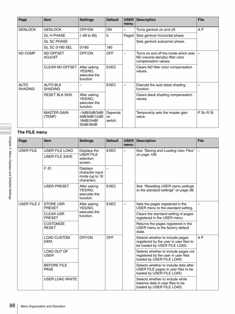
88
Chapter 5 M
enu Displays and D
etailed Settings
The FILE menu
GENLOCK GENLOCK OFF/ON ON – Turns genlock on and off. A P
GL H PHASE (–99 to 99) 0 Page5 Sets genlock horizontal phase.
GL SC PHASE Sets genlock subcarrier phase.
GL SC 0/180 SEL 0/180 180
ND COMP ND OFFSET ADJUST
OFF/ON OFF – Turns on and off the mode which sets ND (neutral density) filter color compensation values.
–
CLEAR ND OFFSET After asking YES/NO, executes the function.
EXEC Clears ND filter color compensation values.
AUTO SHADING
AUTO BLK SHADING
– EXEC – Execute the auto black shading function.
–
RESET BLK SHD After asking YES/NO, executes the function.
Clears black shading compensation values.
MASTER GAIN (TEMP)
–3dB/0dB/3dB/6dB/9dB/12dB/18dB/24dB/30dB/36dB
Depends on switch.
Temporarily sets the master gain value.
P Sc R St
Page Item Settings Default USER menu
Description File
USER FILE USER FILE LOAD Displays the USER FILE selection screen.
EXEC – See “Saving and Loading User Files” on page 109.
–
USER FILE SAVE
F. ID Displays character input mode (up to 16 character).
–
USER PRESET After asking YES/NO, executes the function.
EXEC See “Resetting USER menu settings to the standard settings” on page 98.
USER FILE 2 STORE USR PRESET
After asking YES/NO, executes the function.
EXEC – Sets the pages registered in the USER menu to the standard setting.
–
CLEAR USR PRESET
Clears the standard setting of pages registered in the USER menu.
CUSTOMIZE RESET
Returns the pages registered in the USER menu to the factory default state.
LOAD CUSTOM DATA
OFF/ON OFF Selects whether to include pages registered by the user in user files to be loaded by USER FILE LOAD.
A P
LOAD OUT OF USER
Selects whether to include pages not registered by the user in user files loaded by USER FILE LOAD.
BEFORE FILE PAGE
Selects whether to include data after USER FILE pages in user files to be loaded by USER FILE LOAD.
USER LOAD WHITE Selects whether to include white balance data in user files to be loaded by USER FILE LOAD.
Page Item Settings Default USER menu
Description File
Menu Organization and Operation

Chapter 5 M
enu Displays and D
etailed Settings
ALL FILE ALL FILE LOAD Displays the FILE selection screen.
EXEC – Loads ALL file. –
ALL FILE SAVE Saves ALL file.
F.ID Displays character input mode (up to 16 character).
Blank Names ALL file. A
ALL PRESET After asking YES/NO, executes the function.
EXEC Returns items in ALL file to preset values.
–
STORE ALL PRESET
Sets preset values of items in ALL file.
CLEAR ALL PRESET
Clears preset values of items in ALL file.
SCENE FILE s1 – STAN-DARD
– See “Saving and Loading Scene Files” on page 113.
–
s2
s3
s4
s5
sSTANDARD – –
SCENE RECALL Displays the SCENE FILE selection screen.
EXEC
SCENE STORE
F.ID Displays character input mode (up to 16 characters).
Blank Sc
REFERENCE REFERENCE STORE
After asking YES/NO, executes the function.
EXEC – Saves reference file in internal memory.
–
REFERENCE CLEAR
Clears reference file.
REFERENCE LOAD Loads reference file.
REFERENCE SAVE Saves reference file to “Memory Stick”.
F. ID Displays character input mode (up to 16 characters).
Blank Names reference file. R
SCENE WHITE DATA
OFF/ON OFF See “White balance setting data when loading the scene file” on page 114.
A P
Page Item Settings Default USER menu
Description File
89Menu Organization and Operation

90
Chapter 5 M
enu Displays and D
etailed Settings
* “EX” is displayed when the extender is on, and “0.8” is displayed when the shrinker is on.
LENS FILE 1 LENS FILE RECALL Displays the FILE selection screen.
EXEC – Loads lens file. –
LENS FILE STORE Saves lens file.
F. ID Displays character input mode (up to 16 characters).
Blank Names lens file. L
LENS NO OFFSET After asking YES/NO, executes the function.
EXEC Clears lens file. –
SOURCE – MEMORY 1
Displays number of selected lens file.
IRIS GAIN (–99 to 99) 6 Adjusts iris gain value of lens file. L
LENS FILE 2 LENS M VMOD* (–99 to 99) 0 – Sets lens file V SAW shading. L
LENS CENTER H* –48 to 47 0 Compensates horizontal position of lens file center marker.
LENS CENTER V* –15 to 14 0 Compensates vertical position of lens file center marker.
LENS R FLARE* (–99 to 99) 0 Adjusts lens file flare (R).
LENS G FLARE* Adjusts lens file flare (G).
LENS B FLARE* Adjusts lens file flare (B).
LENS W-R OFST* Compensates R value when extender and shrinker used.
LENS W-B OFST* Compensates B value when extender and shrinker used.
LENS FILE 3 SHADING CH SEL R/G/B R – Selects the channel adjusted by this menu.
A P
LENS R/G/B H SAW*
(–99 to 99) 0 Compensates horizontal Saw white shading.
L
LENS R/G/B H PARA*
Compensates horizontal Parabola white shading.
LENS R/G/B V SAW* Compensates vertical Saw white shading.
LENS R/G/B V PARA*
Compensates vertical Parabola white shading.
MEMORY STICK
M.S. FORMAT After asking YES/NO, executes the function.
EXEC – Format “Memory Stick”. –
M.S. IN > JUMP TO OFF/USER/ALL/SCENE/LENS/REFER/USER1
OFF See “Displaying a File-Related Menu Page When Inserting a “Memory Stick”” on page 117.
A P
Page Item Settings Default USER menu
Description File
Menu Organization and Operation

Chapter 5 M
enu Displays and D
etailed Settings
The DIAGNOSIS menu
Page Item Settings Default USER menu
Description File
HOURS METER
RESET METER Displays the RESET METER selection screen.
EXEC – Displays the RESET METER selection screen.
–
DRUM RUNNING 000000H to 999999H
– Display only.
TAPE RUNNING
OPERATION
THREADING 000000 to 999999
DRUM RUNNING–2 000000H to 999999HTAPE RUNNING–2
OPERATION–2
THREADING–2 000000 to 999999
TIME/DATE CLOCK ADJUST Displays the TIME ADJUST selection screen.
EXEC Page8
See “Setting the date/time of the internal clock” on page 105.
–
HOUR 00 to 23 Internal clockMIN 00 to 59
SEC
YEAR 00 to 99
MONTH 01 to 12
DAY 01 to 31
DEV STATUS 1
I/O – – – Display only. –
FP1 OK/NG
FP2
CN
FRAM –
AT OK/NG
EEPROM –
DCP1 OK/NG
DCP2
PA
LSI –
PX OK/NG
BCS
SCI –
SY OK/NG
RM --/OK/NG
91Menu Organization and Operation

92
Chapter 5 M
enu Displays and D
etailed Settings
DEV STATUS 2
AUTO CHECK After asking YES/NO, executes the function.
EXEC – See “Using the auto-check function” on page 120.
–
HUMID TIMER RESET
Resets the humid alarm.
OPTION BOARD
SDI OUTPUT – – – Displays status of installed option board.
–
COMPOSITE VIDEO INPUT
Page Item Settings Default USER menu
Description File
Menu Organization and Operation

Chapter 5 M
enu Displays and D
etailed Settings
Displaying menus
When the camcorder is powered on, flick the MENU switch to the ON position to display the menu on the viewfinder screen and the LCD monitor of the camcorder.If this is the first time the menu has been used after the camcorder has been powered on, the USER menu is displayed. If the menu has been used before, the last accessed page appears.
When the menu is not displayed on the LCD monitorPress the DISP SEL button on the lower left of the LCD monitor to select the CHAR display.
To end menu operationsFlick the MENU switch to OFF.When the DISPLAY switch on the viewfinder is set to ON or the VF DISP item on the VF DISP 1 page is set to ON, the display indicating the current status of the camcorder appears on the viewfinder.
For details, see “Selecting the display items” on page 98.
To display the TOP menuIf the menu is not displayed on the screen, press and hold the MENU knob and flick the MENU switch to the ON position.
Basic menu operations
By pressing and turning the MENU knob, you can set various menu items. In the remainder of this section, the viewfinder screen is generally shown as an example of the menu display, but a similar display also appears on the LCD monitor.
To select the setting items and values on the menuTurn the MENU knob to select in the cases explained below.
To scroll pages
To select a menu to set
To change a setting value
Viewfinder
MENU switch
LCD monitor
POWER switch
MENU knob
? 01 OUTPUT
LCD BRIGHT<L> : 0
LCD BRIGHT<H> : 0
LCD COLOR : 0
TOP ? 02 MONITOR OUT
MONI OUT VFDISP : ON
MONI OUT MENU : ON
MONI OUT TC : ON
MONI OUT MARKER : OFF
MONI OUT ZEBRA : OFF
TOP
When ? blinks, turn the MENU knob to switch pages.
When b appears, turn the MENU knob to move b up and down.
01 OUTPUT
LCD BRIGHT<L> : 0
LCD BRIGHT<H> : 0
LCD COLOR : 0
TOP 01 OUTPUT
LCD BRIGHT<L> : 0
LCD BRIGHT<H> : 0
LCD COLOR : 0
TOP
01 OUTPUT
LCD BRIGHT<L> :? 0
LCD BRIGHT<H> : 0
LCD COLOR : 0
TOP 01 OUTPUT
LCD BRIGHT<L> :? 1
LCD BRIGHT<H> : 0
LCD COLOR : 0
TOP
When ? blinks, turn the MENU knob to change the setting (ON/OFF, value, etc.).
93Menu Organization and Operation
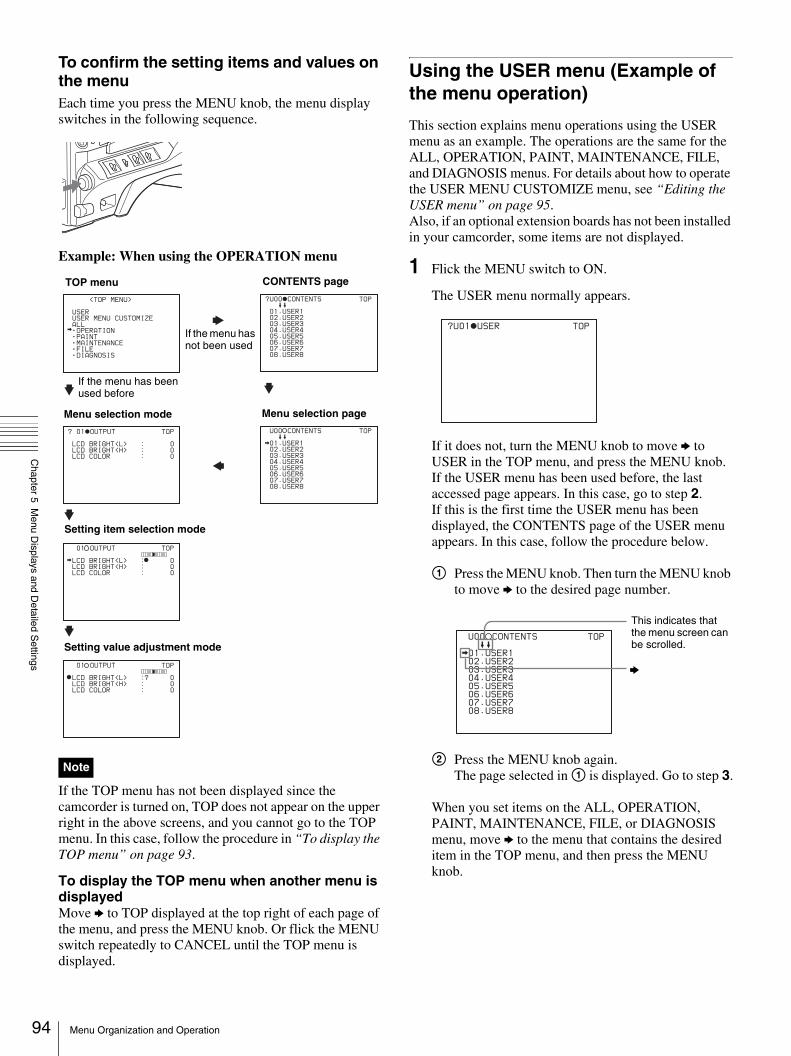
94
Chapter 5 M
enu Displays and D
etailed Settings
To confirm the setting items and values on the menuEach time you press the MENU knob, the menu display switches in the following sequence.
Example: When using the OPERATION menu
If the TOP menu has not been displayed since the camcorder is turned on, TOP does not appear on the upper right in the above screens, and you cannot go to the TOP menu. In this case, follow the procedure in “To display the TOP menu” on page 93.
To display the TOP menu when another menu is displayedMove b to TOP displayed at the top right of each page of the menu, and press the MENU knob. Or flick the MENU switch repeatedly to CANCEL until the TOP menu is displayed.
Using the USER menu (Example of the menu operation)
This section explains menu operations using the USER menu as an example. The operations are the same for the ALL, OPERATION, PAINT, MAINTENANCE, FILE, and DIAGNOSIS menus. For details about how to operate the USER MENU CUSTOMIZE menu, see “Editing the USER menu” on page 95.Also, if an optional extension boards has not been installed in your camcorder, some items are not displayed.
1 Flick the MENU switch to ON.
The USER menu normally appears.
If it does not, turn the MENU knob to move b to USER in the TOP menu, and press the MENU knob.If the USER menu has been used before, the last accessed page appears. In this case, go to step 2.If this is the first time the USER menu has been displayed, the CONTENTS page of the USER menu appears. In this case, follow the procedure below.
1 Press the MENU knob. Then turn the MENU knob to move b to the desired page number.
2 Press the MENU knob again.The page selected in 1 is displayed. Go to step 3.
When you set items on the ALL, OPERATION, PAINT, MAINTENANCE, FILE, or DIAGNOSIS menu, move b to the menu that contains the desired item in the TOP menu, and then press the MENU knob.
Note
LCD BRIGHT<L> :? 0
LCD BRIGHT<H> : 0
LCD COLOR : 0
<TOP MENU>
USER
USER MENU CUSTOMIZE
ALL
OPERATION
PAINT
MAINTENANCE
FILE
DIAGNOSIS
? 01 OUTPUT
LCD BRIGHT<L> : 0
LCD BRIGHT<H> : 0
LCD COLOR : 0
TOP
01 OUTPUT
LCD BRIGHT<L> : 0
LCD BRIGHT<H> : 0
LCD COLOR : 0
TOP
01 OUTPUT TOP
?U00 CONTENTS
01.USER1
02.USER2
03.USER3
04.USER4
05.USER5
06.USER6
07.USER7
08.USER8
TOP
U00 CONTENTS
01.USER1
02.USER2
03.USER3
04.USER4
05.USER5
06.USER6
07.USER7
08.USER8
TOP
TOP menu
If the menu has been used before
Menu selection page
If the menu has not been used
Setting value adjustment mode
Setting item selection mode
CONTENTS page
Menu selection mode
?U01 USER
TOP
U00 CONTENTS
01.USER1
02.USER2
03.USER3
04.USER4
05.USER5
06.USER6
07.USER7
08.USER8
TOP
This indicates that the menu screen can be scrolled.
b
Menu Organization and Operation

Chapter 5 M
enu Displays and D
etailed Settings
2 Turn the MENU knob until the desired page appears.
3 Press the MENU knob.
b and z appear.
4 Turn the MENU knob to move b to the desired item, and then press the MENU knob.
b changes to z, and z changes to ?.
5 Turn the MENU knob to change the setting.
Depending on the direction of turning the knob, the setting value increases, decreases, switches between ON and OFF, etc.
If you want to cancel a change or return to the standard settings, see the next item “To cancel setting” and “To return to the standard settings”.
To interrupt changing the settingsFlick the MENU switch to OFF.By flicking the MENU switch to ON again, the values that were displayed when you interrupted the setting operations will reappear so you can continue making settings.
6 Press the MENU knob.
z changes to b, and ? changes to z. The selection is set.
7 To continue setting other items on the same page, repeat steps from 4 to 6.
8 To end the menu operation, flick the MENU switch to OFF.
The menu disappears from the screen, and the display indicating the current status of the camcorder appears along the top and bottom of the screen.
To cancel settingBefore pressing the MENU knob in step 6 of the above procedure, flick the MENU switch to CANCEL.
To return to the standard settingsBy pressing and holding the MENU knob in step 5 of the above procedure, the settings return to the standard.
To move to another page
When ? appears in front of the page numberTurn the MENU knob to switch pages.
When nothing appears in front of the page numberTurn the MENU knob to move b to the page number, and press the MENU knob. Then Turn the MENU knob to switch pages.
Editing the USER menu
The USER MENU CUSTOMIZE menu allows you to configure a USER menu that consists only of pages and items that you need by adding, deleting or replacing the pages.
To add a new pageThe USER MENU CUSTOMIZE menu allows you to add a new page to the USER menu.While the EDIT page contains factory-preset items, the USER 9 EDIT to USER 19 EDIT pages are all blank in their initial state. You can register up to 10 items, including blank lines, on each of these pages.
1 Display the TOP menu (page 93).
2 Turn the MENU knob to move b to USER MENU CUSTOMIZE, then press the MENU knob.
If this is the first time the USER MENU CUSTOMIZE menu has been displayed, the CONTENTS page of the menu appears.
?U01 USER 1 TOP
IRIS OVERRIDE : OFF
DETAIL LEVEL : 0
MASTER BLACK : 0
BLACK GAMMA : OFF
MASTER BLK GAMMA: 0
COLOR TEMP <P> : 3200
U01 USER 1 TOP
IRIS OVERRIDE : OFF
DETAIL LEVEL : 0
MASTER BLACK : 0
BLACK GAMMA : OFF
MASTER BLK GAMMA: 0
COLOR TEMP <P> : 3200
?U01 USER 1 TOP
IRIS OVERRIDE : OFF
DETAIL LEVEL : 0
MASTER BLACK : 0
BLACK GAMMA : OFF
MASTER BLK GAMMA: 0
COLOR TEMP <P> : 3200
Page number
95Menu Organization and Operation

96
Chapter 5 M
enu Displays and D
etailed Settings
If the USER MENU CUSTOMIZE menu has been used before, the last accessed page appears.
3 If the CONTENTS page is displayed, press the MENU knob. Then turn the MENU knob to move b to one of USER 1 EDIT to USER 19 EDIT, and press the MENU knob again.
If a different page is displayed, turn the MENU knob until the desired page appears, then press the MENU knob.
Example: When selecting the USER 9 EDIT page
4 Press the MENU knob. Then turn the MENU knob to move b to the line where you want to add an item, and press the MENU knob again.
The EDIT FUNCTION page appears.
5 Press the MENU knob. Then turn the MENU knob to move b to INSERT, and press the MENU knob again.
The page for the last added item appears.
6 Add the items as below.
1 Turn the MENU knob until the page that has the desired items appears, then press the MENU knob.
2 Turn the MENU knob to move b to the desired item, then press the MENU knob.
The USER 2 EDIT page appears again, displaying the newly added item.
7 Repeat steps 4 to 6 to add the remaining items.
You can add up to 10 items on one page.
To delete items from a page by using the MENU knob
1 Follow steps 1 to 3 of “To add a new page” on page 95.
2 Press the MENU knob. Then turn the MENU knob to move b to the item that you wan to delete, and press and hold the MENU knob again.
The item is deleted.
To delete items from a page by using the EDIT FUNCTION page
1 Follow steps 1 to 3 of “To add a new page” on page 95.
2 Press the MENU knob. Then turn the MENU knob to move b to the item that you want to delete, and press the MENU knob again.
The EDIT FUNCTION page appears.
3 Turn the MENU knob to move b to DELETE, and press the MENU knob.
The previously displayed page appears again, and the message “DELETE OK? Yes b No” appears at the upper right.
4 To delete, turn the MENU knob to move b to YES, and then press the MENU knob.
To replace items on a page
1 Follow steps 1 to 3 of “To add a new page” on page 95.
2 Press the MENU knob. Then turn the MENU knob to move b to the item that you want to replace, and press the MENU knob again.
The EDIT FUNCTION page appears.
3 Turn the MENU knob to move b to MOVE, then press the MENU knob.
The previously displayed page appears again.
4 Turn the MENU knob to move b to the position where you want to move the item, then press the MENU knob.
The item selected in step 2 moves to the position that you selected in step 4.
?E00 CONTENTS
01.EDIT PAGE
02.USER 1 EDIT
03.USER 2 EDIT
04.USER 3 EDIT
05.USER 4 EDIT
06.USER 5 EDIT
07.USER 6 EDIT
08.USER 7 EDIT
09.USER 8 EDIT
10.USER 9 EDIT
TOP
E10 USER 9 EDIT TOP
EDIT FUNCTION
INSERT
MOVE
DELETE
BLANK
ESC
Menu Organization and Operation

Chapter 5 M
enu Displays and D
etailed Settings
To insert a blank line
1 Follow steps 1 to 3 of “To add a new page” on page 95.
2 Press the MENU knob. Then turn the MENU knob to move b to the item above which you want to insert a blank line.
The EDIT FUNCTION page appears.
3 Turn the MENU knob to move b to BLANK, and press the MENU knob.
The previously displayed page appears again, and a blank line is inserted above the specified item.
You cannot insert a blank line on a page where 10 items have already been registered.
To add/delete/replace pagesYou can add a new page to the USER menu, delete a page from the USER menu, or replace pages, using the EDIT PAGE of the USER MENU CUSTOMIZE menu.
To add a page
1 Display the TOP menu (page 93).
2 Turn the MENU knob to move b to USER MENU CUSTOMIZE, then press the MENU knob.
If this is the first time the USER MENU CUSTOMIZE menu has been displayed, the CONTENTS page appears. If the menu has been used before, the last accessed page appears.
3 If the CONTENTS page is displayed, press the MENU knob. Then turn the MENU knob to move b to EDIT PAGE, and press the MENU knob again.
If a different page is displayed, turn the MENU knob until the EDIT PAGE screen appears.
The EDIT PAGE appears.
4 Press the MENU knob. Then turn the MENU knob to move b to where you want to add the page, then press the MENU knob again.
The EDIT FUNCTION page appears.
5 Turn the MENU knob to move b to INSERT, and press the MENU knob again.
The CONTENTS page appears.
6 Turn the MENU knob to move b to the desired page, then press the MENU knob again.
The number and name of the page selected in step 6 is added above the item selected in step 4.
To cancel adding a pageBefore pressing the MENU knob in step 6, turn the MENU knob to move b to ESC at the top right of the screen, then press the MENU knob.The EDIT PAGE screen appears again.
To delete a page by using the MENU knob
1 Follow steps 1 to 3 of “To add a page”.
2 Press the MENU knob. Then turn the MENU knob to move b to the page that you want to delete, and press and hold the MENU knob.
To delete a page by using the EDIT FUNCTION page
1 Follow steps 1 to 3 of “To add a page”.
2 Press the MENU knob. Then turn the MENU knob to move b to the page that you want to delete, and press the MENU knob again.
The EDIT FUNCTION page appears.
3 Turn the MENU knob to move b to DELETE, and press the MENU knob.
The previously displayed page appears again, and the message “DELETE OK? YES b NO” appears at the upper right.
4 Turn the menu knob to move b to YES, and press the MENU knob.
To replace a page
1 Follow steps 1 to 3 of “To add a page”.
2 Press the MENU knob. Then turn the MENU knob to move b to the page that you want to move, and press the MENU knob again.
The EDIT FUNCTION page appears.
3 Turn the MENU knob to move b to MOVE, then press the MENU knob.
Note
?E01 EDIT PAGE
01.USER 1
02.USER 2
03.USER 3
04.USER 4
05.USER 5
06.USER 6
07.USER 7
08.USER 8
END OF PAGE
TOP
97Menu Organization and Operation

98
Chapter 5 M
enu Displays and D
etailed Settings
The previous screen appears again.
4 Turn the MENU knob to move b to the position to where you want to move the page selected in step 2, and press the MENU knob.
The page selected in step 2 is moved to the position selected in step 4.
Resetting USER menu settings to the standard settings
You can return all settings in the USER menu to the standard settings.
1 Display the USER FILE page of the FILE menu.
For details on menu operations, see “Basic menu operations” on page 93.
2 Press the MENU knob. Then turn the MENU knob to move b to USER PRESET, and press the MENU knob again.
The message “PRESET OK? YES b NO” appears.
3 Turn the MENU knob to move b to YES, and press the MENU knob.
The settings for all items in the USER menu are reset to the standard settings.
Setting the Status Display on the Viewfinder Screen and the LCD Monitor
This section explains the menu settings for the display of the viewfinder screen. These settings are also used for the display of the LCD monitor in the same way.
Selecting the display items
To select the items to be displayed on the viewfinder screen and the LCD monitor from the VF DISP 1 and VF DISP 2 pages of the OPERATION menu, turn on or off the indication next to each item.
1 Display the VF DISP 1 or VF DISP 2 page of the OPERATION menu.
For details on menu operations, see “Basic menu operations” on page 93.
You can select the following items to be displayed on the screen on the VF DISP 1 and VF DISP 2 pages.
VF DISP 1 page
1) The viewfinder screen can be also turned on or off by using the DISPLAY switch of the viewfinder.
2) For detailed information on the display mode, see “Display modes and setting change confirmation/adjustment progress messages” on page 99.
?F01 USER FILE TOP
USER FILE LOAD : EXEC
USER FILE SAVE : EXEC
F.ID : sssssssssssssssss
USER PRESET : EXEC
F01 USER FILE
PRESET OK? YES NO
USER FILE LOAD : EXEC
USER FILE SAVE : EXEC
F.ID : sssssssssssssssss
USER PRESET : EXEC
Item Description
VF DISP Turns on or off the viewfinder screen. 1)
VF DISP MODE Selects the display mode. 2)
DISP EXTENDER Displays extender.
DISP FILTER Displays types of the ND filter.
DISP WHITE Displays selected white balance memory.
DISP GAIN Displays gain value.
DISP SHUTTER Displays shutter speed and ECS mode.
DISP AUDIO Displays audio level.
DISP TAPE Displays remaining tape capacity.
DISP IRIS Displays iris opening.
Setting the Status Display on the Viewfinder Screen and the LCD Monitor

Chapter 5 M
enu Displays and D
etailed Settings
VF DISP 2 page
1) When an Anton Bauer Intelligent Battery System or a BP-GL65/GL95/L60S battery pack is used, the setting of this item determines the display as follows. INT: The remaining battery capacity is shown as a percentage when there is a change, and when the capacity is low. AUTO: The remaining battery capacity is shown as a percentage, except that when this is impossible the battery voltage appears. VOLT: The battery voltage is shown.
2) Displays only when an external VTR is connected to the (i.LINK) DV OUT connector.
2 Select whether the item should appear in the viewfinder screen (the ON setting), or not appear (the OFF setting).
Display modes and setting change confirmation/adjustment progress messages
You can limit or suppress the messages that give details of setting changes and adjustment progress and results by setting a display mode.The conditions under which messages are displayed and their correspondence with the display mode are as follows.
Setting change confirmation/adjustment progress messages and display modesY: Message is displayed.N: Message is not displayed.
* This is also displayed for about 3 seconds when the SHUTTER switch is set to ON.
To change the display mode
1 Display the VF DISP 1 page of the OPERATION menu.
For details on menu operations, see “Basic menu operations” on page 93.
2 Set VF DISP MODE to either 1, 2, or 3.
The display mode setting changes.
For details about the settings of 1 to 3, see the chart above.
Item Description
DISP COLOR TEMP
Displays the color temperature.
DISP BATT REMAIN1)
Displays the battery voltage and remaining capacity of an internal battery pack or an external battery connected to the DC IN connector.
DISP DC IN Displayed when the power is supplied from an external battery connected to the DC IN connector.
DISP 16:9/4:3 ID Displays the 16:9/4:3 mode indicator.
DISP VTR STATUS Displays the VTR operating status.
DISP VTR TRIGGER 2)
Displays the REC TRIGGER switch setting.
DISP TIME CODE Displays the time code.
DISP REC FORMAT
Displays the recording format.
Message display condition
Message Display mode setting
1 2 3
When the filter selection has been changed
ND: n (where n = 1, 2, 3, 4)
N N Y
When the gain setting has been changed
GAIN: n (where n = -3dB, 0dB, 3dB, 6dB, 9dB,12dB, 18dB, 24dB, 30dB, 36dB)
N N Y
When the setting of the WHITE BAL switch has been changed
WHITE: n (where n = A CH, B CH, PRESET) or ATW: RUN
N N Y
When the OUTPUT/DCC switches has been set to DCC ON or OFF
DCC: ON (or OFF) N Y Y
When the shutter speed and mode setting has been changed*
: SS: 1/100 (or 1/125, 1/250, 1/500, 1/1000, 1/2000, ECS, SLS)
N Y Y
When the black or white balance has been adjusted
E.g. WHITE: OK N Y Y
99Setting the Status Display on the Viewfinder Screen and the LCD Monitor

100
Chapter 5 M
enu Displays and D
etailed Settings
Setting the marker display
You can switch the display of the center and safety zone markers on or off and select whether the area indicated by the safety zone marker is 80%, 90%, 92%, or 95% of the screen area.
1 Display the MARKER 1 page of the OPERATION menu.
For details on menu operations, see “Basic menu operations” on page 93.
You can set the following items on the MARKER 1 page.
The items above, except for ASPECT MASK (4:3), are not displayed on the LCD monitor.
2 Perform the settings for each item.
For details about the setting item, see the OPERATION menu list.
Setting the viewfinder
Use the VF SETTING page of the OPERATION menu to select items related to the viewfinder.
1 Display the VF SETTING page of the OPERATION menu.
For details on menu operations, see “Basic menu operations” on page 93.
You can set the following items on the VF SETTING page.
1) When you use the viewfinder which is not equipped with the ZEBRA switch, turns the display on or off using this item. When you use the viewfinder with the ZEBRA switch, the most recent operation of the ZEBRA switch and this menu operation is effective.
2) The sharpness setting at the viewfinder does not affect the recorded image.
3) When the VF ASPECT item is set to AUTO, this is linked to the setting of the 16:9/4:3 SELECT item on the FORMAT page. When the VF ASPECT item is set to 16:9, but 4:3 is selected on the FORMAT page, then it is not possible to mix the zebra display and marker display signals on the output signal from the MONITOR OUT connector.
2 Perform the settings for each item.
Item Description
MARKER Not to display all markers, set to OFF.
CENTER To display the center marker, set to ON.
SAFETY ZONE To display the safety zone, set to ON.
SAFETY AREA Selects the safety zone range.
ASPECT (DSR-450WS/450WSP only)
To display the aspect marker, set to ON.
ASPECT SELECT (DSR-450WS/450WSP only)
Selects the type of the aspect marker.
ASPECT MASK (4:3) (DSR-450WS/450WSP only)
To make the areas out of the selected aspect marker dimmer, set to ON.
ASPECT MASK LVL (DSR-450WS/450WSP only)
Sets the mask level (1/2, 1/4 or 1/8), when the ASPECT MASK is set to ON.
100% MARKER To display the effective pixel area, set to ON.
Note
Item Description
ZEBRA Turns the zebra display ON or OFF. 1)
ZEBRA SELECT Selects ZEBRA 1, ZEBRA 2 or BOTH.
ZEBRA 1 DET LVL Adjusts the level of the zebra 1 display (20% to 70%). (Factory setting is 70%.)
ZEBRA 1 APT LVL Adjusts the aperture level of the zebra 1 display (1 to 10).
ZEBRA 2 DET LVL Adjusts the level of the zebra 2 display. (Factory setting is 100%.)
VF DETAIL LEVEL Adjusts the sharpness of the viewfinder (–99 to 0 to 99). 2) Turns the VF detail function on or off and adjusts the level.
VF ASPECT (DSR-450WS/450WSP only)
Selects the viewfinder aspect ratio (AUTO/16:9). 3)
Setting the Status Display on the Viewfinder Screen and the LCD Monitor

Chapter 5 M
enu Displays and D
etailed Settings
Recording shot data superimposed on the color bars
In the SHOT DISP page of the OPERATION menu, you can select which shot data is recorded superimposed on the color bars. You can also select which of the shot IDs (1 to 4) set in the SHOT ID page is recorded superimposed on the picture.
1 Display the SHOT DISP page of the OPERATION menu.
For details on menu operations, see “Basic menu operations” on page 93.
You can set the following items on the SHOT DISP page.
2 Set each item to ON/OFF (whether or not to record the selected item superimposed).
To carry out superimposed recordingTo actually record the items selected for superimposed recording on the SHOT DISP page, set the OUTPUT/DCC switch to BARS, DCC OFF. The items selected for superimposed recording appear on the screen and are recorded superimposed on the color bars.
Setting the shot ID
On the SHOT ID page of the OPERATION menu, you can set a shot ID of up to 12 alphanumeric characters, spaces, and symbols. When the OUTPUT/DCC switch is set to BARS, DCC OFF, this shot ID is output with the color bar signal. The shot ID comprises ID-1 to ID-4, and you can select the shot ID to be recorded superimposed on the color bars on the SHOT DISP page.
When the menu is displayed, the shot ID is not displayed even if the color bar signal is output.
1 Display the SHOT ID page of the OPERATION menu.
For details on menu operations, see “Basic menu operations” on page 93.
2 Press the MENU knob. Then turn the MENU knob to move b to the ID (one of ID-1 to ID-4) you want to set, and press the MENU knob again.
x appears over the first character position in the string, and characters can now be input.
3 Enter or change the characters.
When you are entering the shot ID for the first time, go to step 2.
1 Turn the MENU knob to move x to the character which you want to change, then press the MENU knob. A character table appears.
Item Description
SHOT DATE Selects whether or not the shot data is superimposed.
SHOT TIME Selects whether or not shot time is superimposed.
SHOT MODEL NAME
Selects whether or not the model name is superimposed.
SHOT SERIAL NO Selects whether or not the serial number is superimposed.
SHOT ID SEL Selects whether or not the shot ID set on the SHOT ID page is superimposed. To carry out superimposed recording, select the SHOT ID number (1 to 4).
SHOT 16:9 ID Selects whether or not the 16:9 mode indicator is superimposed (when selecting 16:9 aspect ratio).
SHOT BLINK CHARA
Selects whether or not the blinking character is superimposed.
Note
? 12 SHOT ID
ID-1 :?x ID-2 : ssssssssssss ID-3 : ssssssssssss ID-4 : ssssssssssss
TOP
12 SHOT ID
ID-1 :?x ID-2 : ssssssssssss ID-3 : ssssssssssss ID-4 : ssssssssssss
i#$%&'()*+,-./012345678
9:;<=>?@ABCDEFGHIJKLMNOP
QRSTUVWXYZ[ ]abcdefghijk
lmnopqrstuvwxyz~
INS DEL RET ESC END
TOP
12 SHOT ID
ID-1 :? x ID-2 : ssssssssssss ID-3 : ssssssssssss ID-4 : ssssssssssss
i#$%&'()*+,-./012345678
9:;<=>?@ABCDEFGHIJKLMNOP
QRSTUVWXYZ[ ]abcdefghijk
lmnopqrstuvwxyz~
INS DEL RET ESC END
TOP
101Setting the Status Display on the Viewfinder Screen and the LCD Monitor

102
Chapter 5 M
enu Displays and D
etailed Settings
2 Turn the MENU knob until x moves to the character position that you want to select, then press the MENU knob.
4 Repeat step 3 for each of the remaining characters.
5 When the input is complete, turn the MENU knob to move x over END, then press the MENU knob.
This ends the input, and returns to the SHOT ID page.
To insert a spaceIn step 3 above, move x over INS, and press the MENU knob. To cancel inserting a space, move x to RET, and press the MENU knob.
To delete a characterIn step 3 of “Setting the shot ID” on page 101, move x over DEL, and press the MENU knob. This deletes the character under x in the shot ID row.To cancel deleting the character, move x over RET, and press the MENU knob.
To cancel changing shot IDBefore executing step 5 of “Setting the shot ID” on page 101, move b to ESC, then press the MENU knob.
Displaying the status confirmation windows
You can confirm the settings or status of the camcorder on the screen by displaying the following two windows.• CAMERA STATUS window• VTR STATUS window
Display content of the window
CAMERA STATUS window
This window allows you to confirm the assigned function of the ASSIGN switches and the output signal of the VIDEO OUT connector.
VTR STATUS window
This window allows you to confirm the following items related to VTR.• Recording format• Audio bit rate• Setting condition of DF/NDF• Condition of Interval Rec• Trigger mode• Standby-off timer settingYou can use the SET STATUS page of the OPERATION menu to set whether or not the status confirmation windows are displayed.
Example: When entering the letter “+”
ID-1 :? +
ID-2 : ssssssssssss ID-3 : ssssssssssss ID-4 : ssssssssssss
i#$%&'()*+,-./012345678
9:;<=>?@ABCDEFGHIJKLMNOP
QRSTUVWXYZ[ ]abcdefghijk
lmnopqrstuvwxyz~
ESC END
12 SHOT ID TOP
ID-1 : CM 015
ID-2 : ssssssssssss ID-3 : ssssssssssss ID-4 : ssssssssssss
$%&'()*+,-./0123456789:
;<=>?@ABCDEFGHIJKLMNOPQR
STUVWXYZ[\]_
INS DEL RET ESC END
12 SHOT ID
ID-1 : CM015
ID-2 : ssssssssssss ID-3 : ssssssssssss ID-4 : ssssssssssss
$%&'()*+,-./0123456789:
;<=>?@ABCDEFGHIJKLMNOPQR
STUVWXYZ[\]_
INS DEL RET ESC END
TOP
12 SHOT ID TOP
Move x over INS.
Space inserted.
CAMERA STATUS
FORMAT: I
ASSIGN<1> ATW <2> OFF
<3> OFF <4> OFF
FRONT AUDIO VOL : ENABLE
ZEBRA :OFF SELECT: 1
DET 70% APT: 10%
DET2 100%
VTR STATUS
16bit DF F.MIC:MONO
REC FORMAT : DVCAM
AUDIO MODE : FS32K
DF/NDF : DF
INTERVAL REC : OFF
REC TIME : 0.5S
INTERVAL TIME : 30S
VTR TRIGGER MODE : ----
STANDBY OFF TIMER: 1MIN
Setting the Status Display on the Viewfinder Screen and the LCD Monitor

Chapter 5 M
enu Displays and D
etailed Settings
To display the status confirmation windowsFlick the MENU switch to STATUS when the menu is not displayed.
To disable display of the status confirmation windows
1 Display the SET STATUS page of the OPERATION menu.
For details on menu operations, see “Basic menu operations” on page 93.
You can set the following items on the SET STATUS page.
2 Perform the settings for each item.
Adjustments and Settings from Menus
Setting gain values for the GAIN switch positions
You can set the gains corresponding to the L, M, and H positions of the GAIN switch, which switches the gain of the video amplifier.
1 Display the GAIN SW page of the OPERATION menu.
For details on menu operations, see “Basic menu operations” on page 93.
You can set the following items on the GAIN SW page.
2 Perform the settings for each item corresponding to the switch position (GAIN LOW, GAIN MID, GAIN HIGH, and GAIN TURBO).
Any of –3, 0, 3, 6, 9, 12, 18, 24, 30, or 36 dB can be set in any sequence.
To change the gain corresponding to another switch position, repeat this step.
Item Description
STATUS CAMERA Selects whether or not the CAMERA STATUS window is displayed.
STATUS VTR Selects whether or not the VTR STATUS window is displayed.
MENU
STATUSCANCEL
ON OFF
Each time you flick the switch to STATUS, the window switches. After 10 seconds, the window disappears automatically.
Item Description
GAIN LOW Sets the gain value corresponding to the L position of the GAIN switch.
GAIN MID Sets the gain value corresponding to the M position of the GAIN switch.
GAIN HIGH Sets the gain value corresponding to the H position of the GAIN switch.
GAIN TURBO When assigning TURBO to the ASSIGN switch, sets the gain value corresponding to the ASSIGN switch (page 106).
TURBO SW IND OFF: When you operate the GAIN switch after pressing the ASSIGN switch that is assigned to TURBO, the gain value is changed according to the ASSIGN switch position.ON: When TURBO GAIN set by pressing the ASSIGN switch that is assigned to TURBO, the gain value is not changed even if you set the GAIN switch, until you press the ASSIGN switch once more.
103Adjustments and Settings from Menus
104
Chapter 5 M
enu Displays and D
etailed Settings
Selecting the output signals (DSR-450WS/450WSP only)
When the CBK-SD01 SDI Output Board is installed, you can select the type of video signals from the VIDEO OUT connector on the OUTPUT page. You can select either VBS or SDI.Please note that only the picture obtained during recording is displayed on a CBK-SD01 SDI Output Board. Playback picture cannot be output.
1 Display the OUTPUT page of the OPERATION menu.
For details on menu operations, see “Basic menu operations” on page 93.
2 Press the MENU knob. Then turn the MENU knob to move b to REAR BNC OUT SEL, and press the MENU knob again.
b changes to z and z changes to ?.
3 Turn the MENU knob to change the desired setting, and press the MENU knob.
The settings of SDI and VBS are follows.
z changes to b and ? changes to z. The selection is set.
Setting the color temperature manually
You can adjust the value of the white balance manually by setting the color temperature.
1 Display the WHITE page of the PAINT menu.
For details on menu operations, see “Basic menu operations” on page 93.
You can set the following items on the WHITE page.
The above table shows the adjustment of the white balance of channel A. Items followed by <B> are used to adjust the white balance of channel B.
2 Perform the settings for each item.
Setting value Description
SDI Outputs the SDI signal. When SDI is selected, connect to the SDI IN connector of the video monitor.
VBS Outputs the analog composite video signal. When VBS is selected, connect to the VIDEO IN connector of the video monitor. This setting allows you to save the power.
Item Description
COLOR TEMP <A>
Sets the color temperature for the desired value. Adjust the value while looking at the real image because error tends to be bigger for adjustment of high color temperature.
COLOR FINE <A> Adjusts the value more precisely when the color temperature adjustment through COLOR TEMP is not satisfactory.
R GAIN <A> Changes only the value of R GAIN.
B GAIN <A> Changes only the value of B GAIN.
D5600K <A> Sets the color temperature to approximately 5600K.
Adjustments and Settings from Menus

Chapter 5 M
enu Displays and D
etailed Settings
Specifying an offset for the auto white balance setting
By setting an offset for the value of auto white balance, you can make the picture warmer or colder.
1 Display the OFFSET WHT page of the OPERATION menu.
For details on menu operations, see “Basic menu operations” on page 93.
You can set the following items in the OFFSET WHT page.
2 Set the WHITE BAL switch to the channel (A or B) that you want to set.
If the WHITE BAL switch is not set to A or B, the adjusted value does not affect the video output even though you follow the step below.
3 Perform the settings for each item.
If you want to set the another channel, go back to step 2.
Setting the date/time of the internal clock
You can set or change the date and time of the internal clock. The date and time set here are reflected in the time code.
1 Display the TIME/DATE page of the DIAGNOSIS menu.
For details on menu operations, see “Basic menu operations” on page 93.
2 Press the MENU knob. Then turn the MENU knob to move b to CLOCK ADJUST, and press the MENU knob again.
The TIME ADJUST screen appears.You can set the following items on the TIME ADJUST screen.
3 Set the each item to the desired value.
4 When you finish settings, turn the MENU knob to move b to OK, then press the MENU knob.
The internal clock is set with the date and time set in step 3. The TIME/DATE page of the DIAGNOSIS menu appears again. The time set on the TIME ADJUST screen displayed.
To cancel the settingBefore executing step 4, move b to ESC and press the MENU knob.All settings or changes are discarded and the TIME/DATE page appears again.
Item Description
OFFSET WHITE <A>
Selects if the offset adjusted on this page is added to the white balance for channel A.
WARM-COOL <A> When OFFSET WHITE <A> is ON, sets the offset for the white balance of channel A, using the color temperature. Adjust the value while looking at the real image because error tends to be bigger for adjustment of high color temperature.
COLOR FINE <A> Adjusts the value more precisely if the adjustment by WARM-COOL <A> is not satisfactory.
OFFSET WHITE <B>
Selects if the offset adjusted on this page is added to the white balance for channel B.
WARM-COOL <B> When OFFSET WHITE <B> is ON, sets the offset for the white balance of channel B, using the color temperature. Adjust the value while looking at the real image because error tends to be bigger for adjustment of high color temperature.
COLOR FINE <B> Adjusts the value more precisely if the adjustment by WARM-COOL <B> is not satisfactory.
Note
Item Description
HOUR Sets the hour value.
MIN Sets the minutes value.
SEC Sets the seconds value.
YEAR Sets the year.
MONTH Sets the month.
DAY Sets the day.
?D02 TIME/DATE TOP
CLOCK ADJUST : EXEC
HOUR : 12
MIN : 55
SEC : 58
YEAR : 00
MONTH : 07
DAY : 31
105Adjustments and Settings from Menus
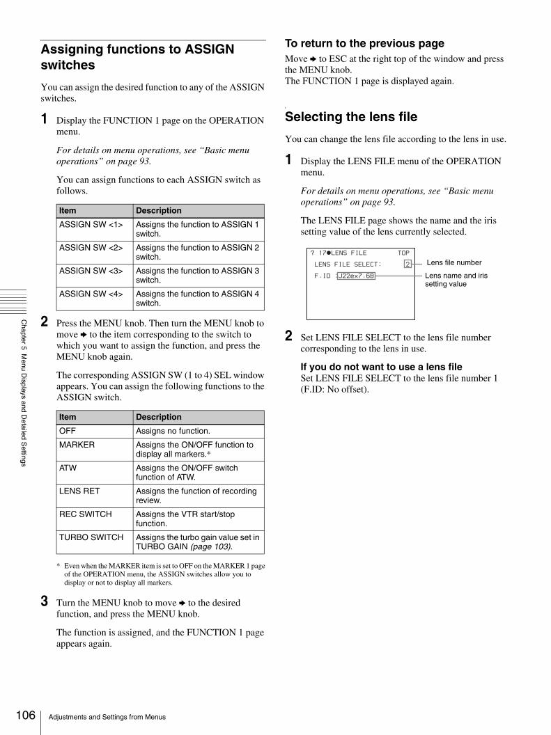
106
Chapter 5 M
enu Displays and D
etailed Settings
Assigning functions to ASSIGN switches
You can assign the desired function to any of the ASSIGN switches.
1 Display the FUNCTION 1 page on the OPERATION menu.
For details on menu operations, see “Basic menu operations” on page 93.
You can assign functions to each ASSIGN switch as follows.
2 Press the MENU knob. Then turn the MENU knob to move b to the item corresponding to the switch to which you want to assign the function, and press the MENU knob again.
The corresponding ASSIGN SW (1 to 4) SEL window appears. You can assign the following functions to the ASSIGN switch.
* Even when the MARKER item is set to OFF on the MARKER 1 page of the OPERATION menu, the ASSIGN switches allow you to display or not to display all markers.
3 Turn the MENU knob to move b to the desired function, and press the MENU knob.
The function is assigned, and the FUNCTION 1 page appears again.
To return to the previous pageMove b to ESC at the right top of the window and press the MENU knob.The FUNCTION 1 page is displayed again.
Selecting the lens file
You can change the lens file according to the lens in use.
1 Display the LENS FILE menu of the OPERATION menu.
For details on menu operations, see “Basic menu operations” on page 93.
The LENS FILE page shows the name and the iris setting value of the lens currently selected.
2 Set LENS FILE SELECT to the lens file number corresponding to the lens in use.
If you do not want to use a lens fileSet LENS FILE SELECT to the lens file number 1 (F.ID: No offset).
Item Description
ASSIGN SW <1> Assigns the function to ASSIGN 1 switch.
ASSIGN SW <2> Assigns the function to ASSIGN 2 switch.
ASSIGN SW <3> Assigns the function to ASSIGN 3 switch.
ASSIGN SW <4> Assigns the function to ASSIGN 4 switch.
Item Description
OFF Assigns no function.
MARKER Assigns the ON/OFF function to display all markers.*
ATW Assigns the ON/OFF switch function of ATW.
LENS RET Assigns the function of recording review.
REC SWITCH Assigns the VTR start/stop function.
TURBO SWITCH Assigns the turbo gain value set in TURBO GAIN (page 103).
? 17 LENS FILE
LENS FILE SELECT: 2
F.ID :J22ex7.6B
TOP
Lens file number
Lens name and iris setting value
Adjustments and Settings from Menus

Chapter 5 M
enu Displays and D
etailed Settings
Selecting the aspect ratio (DSR-450WS/450WSP only)
You can select the aspect ratio of the video output signal.
1 Display the FORMAT menu of the OPERATION menu.
For details on menu operations, see “Basic menu operations” on page 93.
2 Set 16:9/4:3 SELECT to the desired aspect ratio.
To display the aspect ratio of 16:9 or 4:3 on the viewfinderBy setting the DISP 16:9/4:3 ID item to ON on the VF DISP 2 page of the OPERATION menu, “16:9” or “4:3” appears on the viewfinder screen according to the setting of the procedure above.
For details, see “Selecting the display items” on page 98.
To display “16:9” in color barsBy setting the SHOT 16:9 ID item to ON on the SHOT DISP page of the OPERATION menu, you can record a “16:9” mode indicator superimposed on the color bars.
For details, see “Recording shot data superimposed on the color bars” on page 101.
NTSC (DSR-450WS)
PAL (DSR-450WSP)
? 18 FORMAT
16:9/4:3 SELECT : 16:9
WIDE ID : ON
SCAN MODE : I
107Adjustments and Settings from Menus

108
Chapter 5 M
enu Displays and D
etailed Settings
Setting the CCD scan mode (DSR-450WS/450WSP only)
Since the camcorder has CCDs that use an “all pixels readout method,” a progressive scan mode is also available in addition to the conventional interlace scan mode.You can select either of the following modes using the FORMAT page of the OPERATION menu.
• I (interlace scan) mode• PsF (progressive scan) mode• 24P mode (DSR-450WS only)
Each mode is described below using timing charts.
I (interlace scan) mode
PsF (progressive scan) mode
24P mode
To set the CCD scan modeThe scan mode of the camcorder has been set to I (interlace scan) mode at the factory. The FORMAT page of the OPERATION menu allows you to change the CCD scan mode to PsF (progressive scan) mode or 24P mode.
The video signal of an odd scanning line and that of an even scanning line are output from the CCD alternately. Thus, the timing of the odd-field video signal and even field video signal are different.
O: Odd E: Even
CCD output
Video output signal
The video signal of an odd scanning line and that of an even scanning line are output from the CCD at the same time. Then they are sent to the memory and separated into odd-field and even-field scanning lines. Thus the timing of an odd-field video signal and an even-field video signal are the same.
O: Odd E: Even
CCD output
Video output signal
A O
A ( O + E ) B ( O + E ) C ( O + E ) D ( O + E ) A ( O + E )
A E B O B E B O C E C O D E D O D E A O A E
O: Odd E: Even
After reading from the CCDs in 24P mode (23.98 frames per second), a pull-down conversion is carried out to the 30 frames (29.97 frames per second) of the normal progressive scan mode.
1/29.97 seconds
1/23.98 seconds
CCD output
Video output signal
Adjustments and Settings from Menus
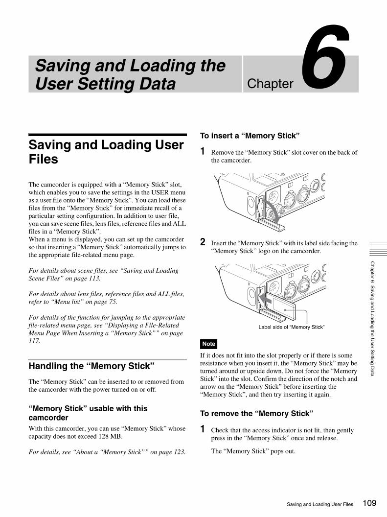
hapter
CSaving and Loading the User Setting DataChapter 6 S
aving and Loading the User S
etting Data
Saving and Loading User Files
The camcorder is equipped with a “Memory Stick” slot, which enables you to save the settings in the USER menu as a user file onto the “Memory Stick”. You can load these files from the “Memory Stick” for immediate recall of a particular setting configuration. In addition to user file, you can save scene files, lens files, reference files and ALL files in a “Memory Stick”.When a menu is displayed, you can set up the camcorder so that inserting a “Memory Stick” automatically jumps to the appropriate file-related menu page.
For details about scene files, see “Saving and Loading Scene Files” on page 113.
For details about lens files, reference files and ALL files, refer to “Menu list” on page 75.
For details of the function for jumping to the appropriate file-related menu page, see “Displaying a File-Related Menu Page When Inserting a “Memory Stick”” on page 117.
Handling the “Memory Stick”
The “Memory Stick” can be inserted to or removed from the camcorder with the power turned on or off.
“Memory Stick” usable with this camcorderWith this camcorder, you can use “Memory Stick” whose capacity does not exceed 128 MB.
For details, see “About a “Memory Stick”” on page 123.
To insert a “Memory Stick”
1 Remove the “Memory Stick” slot cover on the back of the camcorder.
2 Insert the “Memory Stick” with its label side facing the “Memory Stick” logo on the camcorder.
If it does not fit into the slot properly or if there is some resistance when you insert it, the “Memory Stick” may be turned around or upside down. Do not force the “Memory Stick” into the slot. Confirm the direction of the notch and arrow on the “Memory Stick” before inserting the “Memory Stick”, and then try inserting it again.
To remove the “Memory Stick”
1 Check that the access indicator is not lit, then gently press in the “Memory Stick” once and release.
The “Memory Stick” pops out.
Note
Label side of “Memory Stick”
109Saving and Loading User Files

110
Chapter 6 S
aving and Loading the User S
etting Data
2 Pull the “Memory Stick” towards you to withdraw it from the slot.
Do not remove the “Memory Stick” while the access indicator is lit. You may lose data, or damage the “Memory Stick”.
To protect saved dataTo prevent accidental erasure of important setup data, slide the LOCK switch on the “Memory Stick” right to the write protect position.
It is now impossible to write or delete data on the “Memory Stick”. If you try to do so, the message “MEMORY STICK LOCKED” appears and the data cannot be overwritten or deleted.
Notes on using and storing the “Memory Stick”• Avoid touching the connector of the “Memory Stick” or
contacting it with a metal object.• When attaching a label to the “Memory Stick”, use only
the label supplied for the “Memory Stick”.• Do not drop, bend, or submit the “Memory Stick” to
external shock.• Do not disassemble or modify the “Memory Stick”.• Avoid getting liquids on the “Memory Stick”.• Avoid using or storing the “Memory Stick” in a location
subject to:- extremely high temperature such as the hot inside of a
car or the outdoors exposed to a burning sun, or a place near a heater.
- direct sunlight.• When storing and carrying the “Memory Stick”, keep it
in its original case to ensure protection of important data.• Do not format the “Memory Stick” using a PC.
Format the “Memory Stick” on the MEMORY STICK page of the FILE menu.
Saving USER menu data (user file) to the “Memory Stick”
You can save USER menu settings held in the camcorder as user files in the “Memory Stick”.You can save up to 100 user files in the “Memory Stick”.Insert the “Memory Stick” into the “Memory Stick” slot, then proceed as follows.
1 Display the USER FILE page of the FILE menu.
For details on menu operations, see “Basic menu operations” on page 93.
To set a file ID for the data to be savedSet the file ID before going to step 2. For details on setting the file ID, see “To set the file ID” on page 111.
2 Press the MENU knob. Then turn the MENU knob to move b to USER FILE SAVE, and press the MENU knob again.
The USER SAVE page appears.
Up to 20 pages, from P00 to P19, can be used to save user files in the “Memory Stick”. Each page can hold up to 5 files.
3 Turn the MENU knob until the page which contains the desired file number appears, and press the MENU knob.
4 Turn the MENU knob to move b to the desired file number, and press the MENU knob.
Note
Gently press in and release.Check that the access indicator is not lit.
?F01 USER FILE TOP
USER FILE LOAD : EXEC
USER FILE SAVE : EXEC
F.ID : sssssssssssssssss
USER PRESET : EXEC
?P00 USER SAVE
DISPLAY MODE : ALL
001.NEW FILE
002.NEW FILE
003.NEW FILE
004.NEW FILE
005.NEW FILE
ESC
P00 USER SAVE
DISPLAY MODE : ALL
001.NEW FILE
002.NEW FILE
003.NEW FILE
004.NEW FILE
005.NEW FILE
ESC
Saving and Loading User Files

Chapter 6 S
aving and Loading the User S
etting Data
The message “SAVE OK? YES b NO” appears.
5 To carry out the save, turn the MENU knob to move b to YES and press the MENU knob. To cancel, press the MENU knob leaving b pointing to NO.
The access indicator lights. When the saving is completed, the message “COMPLETE” appears and the access indicator goes off.
If no “Memory Stick” has been inserted, the message “NO MEMORY STICK” will appear. Insert a “Memory Stick”.
If you select a file number where data has already been savedThe message “OVERWRITE OK? YES b NO” appears.• To stop overwriting, press the MENU knob leaving
b pointing to NO.• To overwrite, turn the MENU knob to move b to
YES and press the MENU knob.
You can select the information displayed on each USER SAVE or USER LOAD page.
For details, see “To select the display contents” on page 111.
About the USER menu settings to be saved in the “Memory Stick”Settings for items on all pages of the USER menu are saved in the “Memory Stick” as a user file.
If data cannot be savedIf one of the following error messages appears during or after the save operation, then the data was not saved.
To set the file IDBefore data is saved to a “Memory Stick”, it is useful to set a file ID for the “Memory Stick” to identify it. When data is saved to a “Memory Stick”, the file ID is saved to the “Memory Stick” together with the data.
Set the file ID before saving data in the “Memory Stick”. Otherwise, the file ID is not saved with the other data.
1 Display the USER FILE page of the FILE menu.
For details on menu operations, see “Basic menu operations” on page 93.
2 Press the MENU knob. Then turn the MENU knob to move b to F. ID, and then press the MENU knob again.
A character table appears.
3 Follow steps 3 and 4 described in “Setting the shot ID” on page 101 to enter characters.
4 When you finish entering the file ID, turn the MENU knob to move x to END, then press the MENU knob.
The entered file ID is now displayed.
After setting the file ID, carry out the procedure from step 2 in “Saving USER menu data (user file) to the “Memory Stick”” on page 110.
The set file ID is saved in the “Memory Stick” with the data.
To select the display contentsYou can select the contents of the file to be displayed on the USER FILE SAVE page and USER FILE LOAD page
Error message Cause Action
NO MEMORY STICK (flashing)
No “Memory Stick” is inserted.
Insert or reinsert the “Memory Stick”.
MEMORY STICK LOCKED
The LOCK switch on the “Memory Stick” is set to the write protect position.
Set the LOCK switch to the write enable position.
MEMORY STICK ERROR (flashing)
Circuit or “Memory Stick” fault.
Check the circuitry, or replace the “Memory Stick”.
P00 USER SAVE
SAVE OK? YES NO
DISPLAY MODE : ALL
001.NEW FILE
002.NEW FILE
003.NEW FILE
004.NEW FILE
005.NEW FILE
ESC When a file number is shown as NEW FILE, this means that the file is empty. When data is stored in a file number, the file name appears.
Note
F01 USER FILE
USER FILE LOAD : EXEC
USER FILE SAVE : EXEC
F.ID :?x
$%&'()*+,-./0123456789:
;<=>?@ABCDEFGHIJKLMNOPQR
STUVWXYZ[\]_
INS DEL RET ESC END
TOP
13 USER FILE
USER FILE LOAD : EXEC
USER FILE SAVE : EXEC
F.ID : ID-001
USER PRESET : EXEC
TOP
File ID that has been set appears.
111Saving and Loading User Files

112
Chapter 6 S
aving and Loading the User S
etting Data
(P00 to P19), that are the pages to save and call up the data to and from “Memory Stick”.
1 Display the USER FILE LOAD page or the USER FILE SAVE page of the USER FILE menu.
For details on menu operations, see “Basic menu operations” on page 93.
2 Press the MENU knob. Then turn the MENU knob to move b to DISPLAY MODE, and press the MENU knob again.
b changes to z and z changes to ?.
3 Turn the MENU knob until the desired type of the display contents (see the following table) appears, then press the MENU knob.
z changes to b and ? changes to z. The selection is set.
Loading saved data from a “Memory Stick”
The data loaded from the “Memory Stick” overwrites the data saved in the camcorder.
1 Display the USER FILE page of the FILE menu.
For details on menu operations, see “Basic menu operations” on page 93.
2 Press the MENU knob. Then turn the MENU knob to move b to USER FILE LOAD, and press the MENU knob again.
The P00 USER LOAD page appears.
3 Turn the MENU knob until the page which contains the desired file appears.
4 Press the MENU knob. Then turn the MENU knob to move b to the desired file number to be loaded, and press the MENU knob again.
The message “LOAD OK? YES b NO” appears.
5 To carry out the load, turn the MENU knob to move b to YES and press the MENU knob. To cancel, press the MENU knob leaving b pointing to NO.
The access indicator lights. When the load is completed, the message “COMPLETE” appears and the access indicator goes off.The USER FILE page appears again.
If data cannot be loadedIf one of the following error messages appears during or after the load operation, then the data was not loaded.
Display type Description
ALL File ID (10 characters) and date (month/day/year)
F.ID File ID (16 characters)
DATE Saved date (year/month/day/hours/minutes/seconds)
MODEL Information on the model
Note
?P00 USER LOAD
DISPLAY MODE : ALL
001.USER1 JAN/01/04
002.USER2 JAN/15/04
003.NO FILE
004.USER4 FEB/05/04
005.USER5 FEB/20/04
ESC
Error message Cause Action
NO MEMORY STICK (flashing)
No “Memory Stick” is inserted.
Insert or reinsert the “Memory Stick”.
MEMORY STICK ERROR (flashing)
Circuit or “Memory Stick” fault.
Recheck, and consult your Sony representative.
FILE ERROR (flashing)
The “Memory Stick” contains data that cannot be loaded into this camcorder.
You cannot load data saved from another camcorder.
P00 USER LOAD
LOAD OK? YES NO
DISPLAY MODE : ALL
001.USER1 JAN/01/04
002.USER2 JAN/15/04
003.NO FILE
004.USER4 FEB/05/04
005.USER5 FEB/20/04
ESC
Saving and Loading User Files
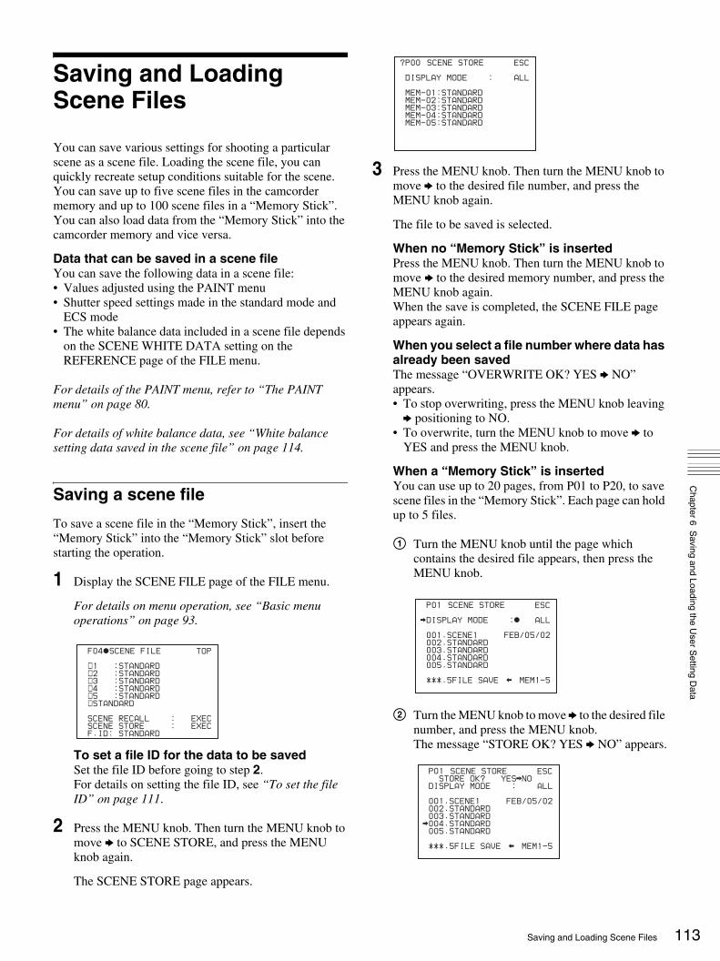
Chapter 6 S
aving and Loading the User S
etting Data
Saving and Loading Scene Files
You can save various settings for shooting a particular scene as a scene file. Loading the scene file, you can quickly recreate setup conditions suitable for the scene. You can save up to five scene files in the camcorder memory and up to 100 scene files in a “Memory Stick”.You can also load data from the “Memory Stick” into the camcorder memory and vice versa.
Data that can be saved in a scene fileYou can save the following data in a scene file:• Values adjusted using the PAINT menu• Shutter speed settings made in the standard mode and
ECS mode• The white balance data included in a scene file depends
on the SCENE WHITE DATA setting on the REFERENCE page of the FILE menu.
For details of the PAINT menu, refer to “The PAINT menu” on page 80.
For details of white balance data, see “White balance setting data saved in the scene file” on page 114.
Saving a scene file
To save a scene file in the “Memory Stick”, insert the “Memory Stick” into the “Memory Stick” slot before starting the operation.
1 Display the SCENE FILE page of the FILE menu.
For details on menu operation, see “Basic menu operations” on page 93.
To set a file ID for the data to be savedSet the file ID before going to step 2.For details on setting the file ID, see “To set the file ID” on page 111.
2 Press the MENU knob. Then turn the MENU knob to move b to SCENE STORE, and press the MENU knob again.
The SCENE STORE page appears.
3 Press the MENU knob. Then turn the MENU knob to move b to the desired file number, and press the MENU knob again.
The file to be saved is selected.
When no “Memory Stick” is insertedPress the MENU knob. Then turn the MENU knob to move b to the desired memory number, and press the MENU knob again.When the save is completed, the SCENE FILE page appears again.
When you select a file number where data has already been savedThe message “OVERWRITE OK? YES b NO” appears.• To stop overwriting, press the MENU knob leaving
b positioning to NO.• To overwrite, turn the MENU knob to move b to
YES and press the MENU knob.
When a “Memory Stick” is insertedYou can use up to 20 pages, from P01 to P20, to save scene files in the “Memory Stick”. Each page can hold up to 5 files.
1 Turn the MENU knob until the page which contains the desired file appears, then press the MENU knob.
2 Turn the MENU knob to move b to the desired file number, and press the MENU knob. The message “STORE OK? YES b NO” appears.
F04 SCENE FILE
s1 :STANDARD s2 :STANDARD s3 :STANDARD s4 :STANDARD s5 :STANDARD sSTANDARD
SCENE RECALL : EXEC
SCENE STORE : EXEC
F.ID: STANDARD
TOP
?P00 SCENE STORE
DISPLAY MODE : ALL
MEM-01:STANDARD
MEM-02:STANDARD
MEM-03:STANDARD
MEM-04:STANDARD
MEM-05:STANDARD
ESC
P01 SCENE STORE
DISPLAY MODE : ALL
001.SCENE1 FEB/05/02
002.STANDARD
003.STANDARD
004.STANDARD
005.STANDARD
***.5FILE SAVE MEM1-5
ESC
P01 SCENE STORE
STORE OK? YES NO
DISPLAY MODE : ALL
001.SCENE1 FEB/05/02
002.STANDARD
003.STANDARD
004.STANDARD
005.STANDARD
***.5FILE SAVE MEM1-5
ESC
113Saving and Loading Scene Files

114
Chapter 6 S
aving and Loading the User S
etting Data
3 To carry out the storing, turn the MENU knob to move b to YES and press the MENU knob. To cancel, press the MENU knob leaving b pointing to NO. You can select the contents of the user file to be displayed on each page of SCENE STORE and SCENE RECALL.
For details, see “To select the display contents” on page 111.
White balance setting data saved in the scene fileThe white balance setting data saved in the scene file refers to the value of white balance during saving, that is, when the WHITE BAL switch is set to A, the adjusted values in memory A are saved in the scene file, and when the WHITE BAL switch is set to PRST, the preset value is saved.
White balance setting data when loading the scene fileThe method for loading the white balance setting data when loading the scene file differs depending on the setting of the SCENE WHITE DATA item on the REFERENCE page.
When SCENE WHITE DATA is set to ONThe white balance setting data saved in the scene file is loaded. (However it is not loaded when the WHITE BAL switch on the camcorder is set to PRST.)
When SCENE WHITE DATA is set to OFFThe white balance setting data is not loaded.
To save scene files from the camcorder memory to the “Memory Stick”You can save five scene files from the camcorder to the “Memory Stick” in a single operation.
1 Display the SCENE FILE page of the FILE menu.
For details on menu operations, see “Basic menu operations” on page 93.
2 Press the MENU knob. Then turn the MENU knob to move b to SCENE STORE, then press the MENU knob again.
3 Turn the MENU knob until the desired SCENE STORE page appears, then press the MENU knob.
4 Turn the MENU knob to move b to 5FILE SAVE b MEM1-5, and press the MENU knob.
The message “STORE OK? YES b NO” appears.
5 To carry out the save, turn the MENU knob to move b to YES and press the MENU knob. To cancel, press the MENU knob leaving b pointing to NO.
When the save is completed, the message “COMPLETE” appears.
If files have been saved in the page selected in step 3, those files are replaced with files loaded from the camcorder memory. For example, files from 001 to 005 are replaced on the above procedure.
To set the file IDBefore the data is saved as a scene file, it is useful to set a file ID to identify it. The set file ID is saved together with the data.
1 Display the SCENE FILE page of the FILE menu.
For details on menu operations, see “Basic menu operations” on page 93.
2 Press the MENU knob. Then turn the MENU knob to move b to F. ID, and press the MENU knob again.
A character table appears.
F05 REFERENCE
REFERENCE STORE : EXEC
REFERENCE CLEAR : EXEC
REFERENCE LOAD : EXEC
REFERENCE SAVE : EXEC
F.ID: sssssssssssssssss
SCENE WHITE DATA: OFF
Note
P01 SCENE STORE
DISPLAY MODE : ALL
001.SCENE1 FEB/05/02
002.SCENE2 FEB/06/02
003.NO FILE
004.SCENE4 FEB/08/02
005.SCENE5 FEB/08/02
***.5FILE SAVE MEM1-5
ESC
P01 SCENE STORE
STORE OK? YES NO
DISPLAY MODE : ALL
001.SCENE1
002.SCENE2
003.NO FILE
004.SCENE4
005.SCENE5
***.5FILE SAVE MEM1-5
ESC
F04 SCENE FILE
!#$%&'()*+,-./012345678
9:;<=>?@ABCDEFGHIJKLMNOP
QRSTUVWXYZ[ ]abcdefghijk
lmnopqrstuvwxyz~
INS DEL RET ESC END
sSTANDARD
SCENE RECALL : EXEC
SCENE STORE : EXEC
F.ID :STANDARD
TOP
Saving and Loading Scene Files

Chapter 6 S
aving and Loading the User S
etting Data
3 Press the MENU knob. Then turn the MENU knob until x moves to the character position that you want to select, then press the MENU knob.
4 Repeat step 3 for each of the remaining characters.
Set the file ID before saving the scene file in the “Memory Stick” or the camcorder memory. Otherwise, the file ID is not saved with the other data.
5 When the input is complete, turn the MENU knob to move x over END, then press the MENU knob.
The file ID is set, and the SCENE FILE page appears again.
Carry out the procedure from step 2 in “Saving a scene file” on page 113. The set file ID is saved together with the data.
To select the display contentsYou can select the items of file information to be displayed on the SCENE STORE pages (P01 to P20) or the SCENE RECALL pages (P01 to P20) used for saving data to or loading data from a “Memory Stick”.
For details to select the item, “To select the display contents” on page 111.
Loading scene files
1 Display the SCENE FILE page of the FILE menu.
For details on menu operations, see “Basic menu operations” on page 93.
2 To load the scene file stored in the camcorder, press the MENU knob. Then turn the MENU knob to move
b to the desired file number, and press the MENU knob again.
s on the left of the file number changes to x. The camcorder is set up according to the loaded scene file.
To cancel the selected scene fileTurn the MENU knob to move b to x, and press the MENU knob. x changes to s. The camcorder returns to the settings before selecting this scene file.
To load a scene file saved in the “Memory Stick”
1 Turn the MENU knob to move b to SCENE RECALL, and press the MENU knob. The SCENE RECALL page appears.
2 Turn the MENU knob until the page which contains the desired file appears.
3 Press the MENU knob. Then turn the MENU knob to move b to the desired file number, and press the MENU knob again. The message “RECALL OK? YES b NO” appears.
3 To carry out the recall, turn the MENU knob to move b to YES and press the MENU knob. To cancel, press the MENU knob leaving b pointing to NO.
When the loading is completed, the message “COMPLETE” appears. The camcorder is set up
Note
Example: When entering the letter “+”
F04 SCENE FILE
!#$%&'()*+,-./012345678
9:;<=>?@ABCDEFGHIJKLMNOP
QRSTUVWXYZ[ ]abcdefghijk
lmnopqrstuvwxyz~
INS DEL RET ESC END
sSTANDARD
SCENE RECALL : EXEC
SCENE STORE : EXEC
F.ID :+TANDARD
TOP
04 SCENE FILE
s1 :STANDARD s2 :STANDARD s3 :STANDARD s4 :STANDARD s5 :STANDARD sSTANDARD
SCENE RECALL : EXEC
SCENE STORE : EXEC
F.ID: SCENE21
TOP
File ID
F04 SCENE FILE
s1 :SCENE 25 x2 :SCENE 26 s3 :SCENE 27 s4 :SCENE 28 s5 :NO FILE sSTANDARD
SCENE RECALL : EXEC
SCENE STORE : EXEC
F.ID :SCENE21
TOP
?P00 SCENE RECALL
DISPLAY MODE : F.ID
MEM-1:STANDARD
MEM-2:STANDARD
MEM-3:STANDARD
MEM-4:STANDARD
MEM-5:NO FILE
ESC
P01 SCENE RECALL
RECALL OK? YES NO
DISPLAY MODE : ALL
001.SCENE1
002.SCENE2
003.NO FILE
004.SCENE4
005.SCENE5
***.5FILE LOAD MEM1-5
ESC
115Saving and Loading Scene Files

116
Chapter 6 S
aving and Loading the User S
etting Data
according to the loaded scene file. If no file is present with a particular file number, this is shown as “NO FILE”.
To load scene files from a “Memory Stick” into the camcorder memoryYou can load up to five scene files stored in the “Memory Stick” into the camcorder memory in a single operation.
1 Display the SCENE FILE page of the FILE menu.
For details on menu operations, see “Basic menu operations” on page 93.
2 Press the MENU knob. Then turn the MENU knob to move b to SCENE RECALL, and press the MENU knob again.
The SCENE RECALL page appears.
3 Turn the MENU knob until the SCENE RECALL page which contains the desired scene files appears.
4 Press the MENU knob. Then turn the MENU knob to move b to 5FILE LOAD B MEM 1-5, and press the MENU knob.
The message “RECALL OK? YES b NO” appears.
5 To carry out the recall, turn the MENU knob to move b YES and press the MENU knob. To cancel, press the MENU knob leaving b pointing to NO.
When loading is complete, the message “COMPLETE” appears and the access indicator goes off.
• The scene files loaded from the “Memory Stick” overwrite data saved in the camcorder memory.
• To load the scene file saved in the camcorder memory when the “Memory Stick” is inserted, return to the P00 SCENE RECALL page and load the desired scene file in the camcorder memory.
• When there is no file to be loaded (shown as “NO FILE”), an existing file of the same number is unaffected. In the example shown in step 4, MEM(3) is not overwritten.
Resetting the settings of the camcorder to the standard settings
You can reset the settings of the camcorder to the settings saved in the reference file (standard settings).
For the items to be saved in the reference file, see page 74.
1 Display the SCENE FILE page of the FILE menu.
For details on menu operations, see “Basic menu operations” on page 93.
2 Press the MENU knob. Then turn the MENU knob to move b to STANDARD, and press the MENU knob again.
s displayed on the left of STANDARD changes to x. When x changes to s once again, the settings of the camcorder are reset to the settings saved in the reference file.
If you press the MENU knob again while x is displayed, the operation is cancelled and the camcorder returns to the settings before STANDARD was selected.
Notes
P01 SCENE RECALL
RECALL OK? YES NO
DISPLAY MODE : ALL
001.SCENE1
002.SCENE2
003.NO FILE
004.SCENE4
005.SCENE5
***.5FILE LOAD MEM1-5
ESC
F04 SCENE FILE
s1 :SCENE 25 s2 :SCENE 26 s3 :SCENE 27 s4 :SCENE 28 s5 :NO FILE xSTANDARD
SCENE RECALL : EXEC
SCENE STORE : EXEC
F.ID :SCENE21
TOP
Saving and Loading Scene Files

Chapter 6 S
aving and Loading the User S
etting Data
Displaying a File-Related Menu Page When Inserting a “Memory Stick”
A “Memory Stick” enables you to save user files, scene files, lens files, reference files and ALL files. The camcorder menu system allows you to make a setting so that when a “Memory Stick” holding these files is inserted while in menu operating mode, a menu page relating to the desired file is automatically displayed on the screen. Thus you can proceed to file operation quickly. This is very convenient especially when you manage data files using “Memory Stick”s.
1 Display the MEMORY STICK page of the FILE menu.
For details on menu operations, see “Basic menu operations” on page 93.
2 Press the MENU knob. Then turn the MENU knob to move b to MS IN > JUMP TO, and press the MENU knob again.
b on the left of MS IN > JUMP TO changes to z and z on the left of setting value changes to ?.
3 Turn the MENU knob to select the desired setting (target FILE menu page).
You can select the setting in the chart below.
4 Press the MENU knob.
z changes to b, and ? changes to z. The selection is set.
In the following cases, displaying the target page is impossible even when the “Memory Stick” is inserted.• When the power is turned on after you insert a “Memory
Stick”• When OFF is selected for the MS IN > JUMP TO item• When any of the following menu pages is already
displayed- A file-related page such as the USER FILE page of the
FILE menu- MEMORY STICK, ALL FILE, SCENE FILE, LENS
FILE, or REFERENCE FILE page
Setting Description
OFF Disables this function. The page does not switch even when “Memory Stick” is inserted.
USER Displays the USER FILE page.
ALL Displays the ALL FILE page.
SCENE Displays the SCENE FILE page.
LENS Displays the LENS FILE 1 page.
REFER Displays the REFERENCE page.
USER 1 Displays the USER 1 page.
F09 MEMORY STICK
FORMAT : EXEC
MS IN > JUMP TO : OFF
TOP
Note
117Displaying a File-Related Menu Page When Inserting a “Memory Stick”

hapter
118
Chapter 7 A
ppendix
CAppendix
Important Notes on Operation
Use and Storage
Do not subject the unit to severe shocksThe internal mechanism may be damaged or the body warped.
Do not cover the unit while operatingPutting a cloth, for example, over the unit can cause excessive internal heat build-up.
After useAlways turn off the power.
Before storing the camcorder for a long periodRemove the battery pack.
Shipping• Remove the cassette before transporting the unit.• If sending the unit by truck, ship, air or other
transportation service, pack it in the shipping carton of the unit.
Care of the unitRemove dust and dirt from the surfaces of the lenses or optical filters using a blower.If the body of the unit is dirty, clean it with a soft, dry cloth. In extreme cases, use a cloth steeped in a little neutral detergent, then wipe dry. Do not use organic solvents such as alcohol or thinners, as these may cause discoloration or other damage to the finish of the unit.
In the event of operating problemsIf you should experience problems with the unit, contact your Sony dealer.
Use and storage locationsStore in a level, ventilated place. Avoid using or storing the unit in the following places.
• In excessive heat or cold (operating temperature range: 0°C to 40°C (32°F to 104°F)) Remember that in summer in warm climates the temperature inside a car with the windows closed can easily exceed 50°C (122°F).
• In damp or dusty locations• Locations where the unit may be exposed to rain• Locations subject to violent vibration• Near strong magnetic fields• Close to radio or TV transmitters producing strong
electromagnetic fields.• In direct sunlight or close to heaters for extended periods
To prevent electromagnetic interference from portable communications devicesThe use of portable telephones and other communications devices near this unit can result in malfunctions and interference with audio and video signals.It is recommended that the portable communications devices near this unit be powered off.
Note on laser beamsLaser beams may damage the CCDs. If you shoot a scene that includes a laser beam, be careful not to let the laser beam be directed into the lens of the camera.
Use at a high temperatureIf the unit is used at a high temperature, white flecks may appear on the screen.
Fitting the zoom lensIt is important to fit the lens correctly, as otherwise damage may result. Be sure to refer to the section “Mounting the lens” on page 28.
Viewfinder• Do not leave the unit with the eyepiece pointing directly
at the sun. The eyepiece lens can concentrate the sun’s rays and melt the interior of the viewfinder.
• Do not use the viewfinder close to strong magnetic fields. This can cause picture distortion.
Important Notes on Operation

Chapter 7 A
ppendix
About the LCD panelsLCD panels are manufactured with extremely high-precision technology that yields effective pixel rates of 99.99% or higher. However, very rarely, one or more pixels may be permanently dark or permanently lit in white, red, blue, or green.This phenomenon is not a malfunction. Such pixels have no effect on the recorded data, and the unit may be used with confidence even if they are present.
Characteristics of CCD sensors
The following effects may appear in the image. They are characteristic of camcorders using CCDs (charge coupled devices), and do not indicate a malfunction.
Bright or dark points of lightA CCD is made with high-precision technology. However, minor bright or dark points of light (red, blue, or green) may sometimes appear. This caused by the structure of the CCD and is not a malfunction.In this case, adjustment of black balance may help to improve this problem.
For details on automatic adjustment of black balance, see “To adjust the black balance” on page 50.
Vertical smearWhen shooting a very bright object, such as a light, the highlight tends to produce vertical tails. This effect is much reduced in this camcorder. (Use of the electronic shutter increases this effect.)
White flecksWhite flecks may appear on the screen during use under high-temperature conditions. White flecks may also appear under normal temperature conditions if the sensitivity is increased (especially to +18 dB or higher).
AliasingWhen patterns of stripes or lines are shot, they may appear jagged.
CondensationIf you move the camcorder from a very cold place to a warm place, or use it in a damp location, condensation may
form on the drum. Then, if the camcorder is operated in this state, recording and playback may not be performed properly. Do the following to prevent this from happening.• When you move or operate the camcorder in an
environment where condensation may form, be sure to insert a cassette in advance and close the cassette compartment lid.
• Whenever you turn on the power, check that the HUMID indicator does not appear on the color LCD. If it appears, wait until it disappears before inserting a cassette.
Vertical tail on the imageMonitor screen
Bright object (electric light, sun, etc.)
119Important Notes on Operation
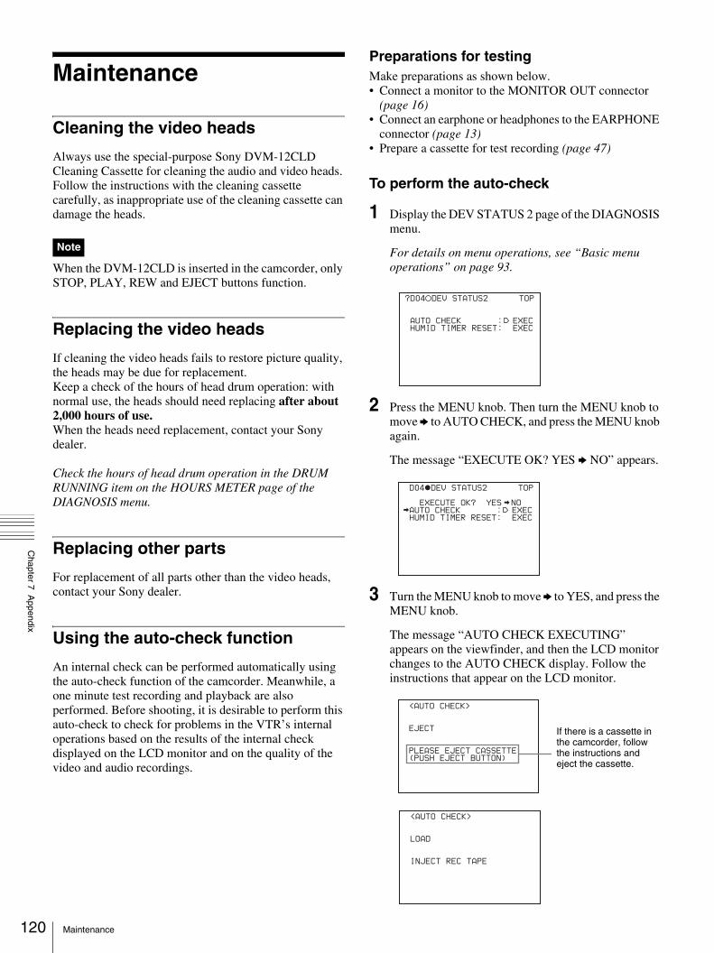
120
Chapter 7 A
ppendix
Maintenance
Cleaning the video heads
Always use the special-purpose Sony DVM-12CLD Cleaning Cassette for cleaning the audio and video heads. Follow the instructions with the cleaning cassette carefully, as inappropriate use of the cleaning cassette can damage the heads.
When the DVM-12CLD is inserted in the camcorder, only STOP, PLAY, REW and EJECT buttons function.
Replacing the video heads
If cleaning the video heads fails to restore picture quality, the heads may be due for replacement. Keep a check of the hours of head drum operation: with normal use, the heads should need replacing after about 2,000 hours of use.When the heads need replacement, contact your Sony dealer.
Check the hours of head drum operation in the DRUM RUNNING item on the HOURS METER page of the DIAGNOSIS menu.
Replacing other parts
For replacement of all parts other than the video heads, contact your Sony dealer.
Using the auto-check function
An internal check can be performed automatically using the auto-check function of the camcorder. Meanwhile, a one minute test recording and playback are also performed. Before shooting, it is desirable to perform this auto-check to check for problems in the VTR’s internal operations based on the results of the internal check displayed on the LCD monitor and on the quality of the video and audio recordings.
Preparations for testingMake preparations as shown below. • Connect a monitor to the MONITOR OUT connector
(page 16)• Connect an earphone or headphones to the EARPHONE
connector (page 13)• Prepare a cassette for test recording (page 47)
To perform the auto-check
1 Display the DEV STATUS 2 page of the DIAGNOSIS menu.
For details on menu operations, see “Basic menu operations” on page 93.
2 Press the MENU knob. Then turn the MENU knob to move b to AUTO CHECK, and press the MENU knob again.
The message “EXECUTE OK? YES b NO” appears.
3 Turn the MENU knob to move b to YES, and press the MENU knob.
The message “AUTO CHECK EXECUTING” appears on the viewfinder, and then the LCD monitor changes to the AUTO CHECK display. Follow the instructions that appear on the LCD monitor.
Note
?D04 DEV STATUS2 TOP
AUTO CHECK : EXEC
HUMID TIMER RESET: EXEC
D04 DEV STATUS2 TOP
EXECUTE OK? YES NO
AUTO CHECK : EXEC
HUMID TIMER RESET: EXEC
<AUTO CHECK>
EJECT
PLEASE EJECT CASSETTE
(PUSH EJECT BUTTON)
If there is a cassette in the camcorder, follow the instructions and eject the cassette.
<AUTO CHECK>
LOAD
INJECT REC TAPE
Maintenance

Chapter 7 A
ppendix
4 Insert the cassette to be used for test recording and playback, and close the cassette lid (page 45).
Check the REC/SAVE switch of the cassette before inserting it, and if the switch is set to SAVE, set it to REC and then insert the cassette.
5 Press the REC button on the camcorder or the VTR button on the lens.
Test recording starts.After about 1 minute, the tape is rewound to the recording start position and playback starts. The following is displayed during playback.
6 Check the recording quality of the playback video on the viewfinder or the monitor. Check the recording quality of the playback audio from the speaker, earphone, or headphones.
If the recording quality is poorA problem may exist regardless of whether or not it is detected by the internal check. Refer to “Troubleshooting” on page 128 and repeat the test. If the recording quality remains poor, contact your Sony dealer.
When playback ends, the results of the internal check are displayed.
7 After confirming the result (see the next section, “Confirming the result”), press the center of the arrow key under the AUDIO adjustment cover.
The auto-check is completed.
To confirm the resultWhen the results of the internal check are normal, the following message appears. You can use the camcorder if there are no problems with the recording quality of the video and audio.
If a problem is indicated in the results, follow the instructions in the table below to check the camcorder and cassette. If no errors can be found, contact your Sony dealer. Also, be sure to check the quality of the playback video and audio (see step 7).
<AUTO CHECK>
REC
PLEASE RECORDING
(PUSH REC BUTTON)
<AUTO CHECK>
PLAY
PLEASE WAIT
Display Diagnostic result
ERROR CODE 000 Ordinary warnings or cautions are indicated. See “Operation Warnings” on page 125.
ERROR CODE 001 Recording on the inserted cassette is not enabled. Insert a cassette that is recordable and repeat the auto-check.
ERROR CODE 002 to 009
A problem in the VTR’s internal operations has occurred. Repeat the auto-check. If the result is the same, contact your Sony dealer.
ERROR CODE 010 to 023
A problem in the VTR’s internal operations has occurred. Clean the video heads using the DVM-12CLD Cleaning Cassette and repeat the auto-check. If the result is the same, contact your Sony dealer.
<AUTO CHECK>
END
COMPLETE
PLEASE EJECT CASSETTE
(PUSH EJECT BUTTON)
121Maintenance

122
Chapter 7 A
ppendix
About i.LINK
The camcorder is equipped with the DV IN/OUT connector based on i.LINK (IEEE1394) standard.This section explains the specifications and features of i.LINK.
What is i.LINK?i.LINK is a digital serial interface designed to integrate the devices equipped with i.LINK connector. By connecting i.LINK devices, i.LINK allows your device to:- Transmit and receive data such as digital audio and
digital video signals in two ways- Control other i.LINK devices- Easily connect with another device using just an i.LINK
cable.Your i.LINK device is capable of connecting AV devices and perform various operations and data transfer. Further availability for connections with versatile equipment and operations will be planned in the future.Other advantages include the following feature. When connecting multiple i.LINK devices, your device cannot only perform operations and data transfer with the directly connected device but also perform them with any of the devices that are connected via other devices. Therefore, you will not need to concern the order of connecting devices.However, depending on the features and specifications of the connected devices, you may need to operate certain functions differently or may not be able to perform certain operations or data transfer.
i.LINK, a nickname for IEEE 1394 that Sony proposed, is a trademark supported by a majority of companies worldwide.IEEE 1394 is an international standard defined by IEEE, The Institute of Electrical and Electronics Engineers, Inc.
The camcorder can be connected to one device with the i.LINK cable (DV cable). When you connect with a device that has two or more i.LINK connectors, refer to the operating instructions supplied with the connected device.
About data transfer speed of i.LINKi.LINK defines a maximum data transfer speed of approximately 100, 200 and 400 Mbps* that are described as S100, S200 and S400 respectively.For i.LINK devices, a maximum data transfer speed that the device supports is identified on “specifications” page of the operating instructions supplied with the device or near its i.LINK connector.
With a device that does not identify the data transfer speed, the maximum data transfer speed that the device supports is S100.When connecting with the device that support different data transfer speed, the actual data transfer speed may be different from those described on the i.LINK connectors.
* What is Mbps?Mega bits per second. A measure of the rate at which data is transmitted per second. In case of 100 Mbps, 100 Mega bits of data can be transmitted per second.
i.LINK operation with your camcorderFor details on operation when other equipment with i.LINK (DV) connector is connected, see page 41.For details on connection with i.LINK cable and necessary software, refer to the operating instructions supplied with the connected device.
Use Sony i.LINK cablesUse Sony i.LINK cables to connect the i.LINK devices.6 pins y 4 pins (For dubbing)6 pins y 6 pins (For dubbing)
i.LINK and are trademarks.
Note
About i.LINK

Chapter 7 A
ppendix
About a “Memory Stick”
What is “Memory Stick”?“Memory Stick” is a new compact, portable and versatile IC (Integrated Circuit) recording medium with a data capacity that exceeds a floppy disk. “Memory Stick” is specially designed for exchanging and sharing digital data among “Memory Stick” compatible products. Because it isremovable, “Memory Stick” can also be used for external data storage.“Memory Stick” is available in two sizes: standard size and compact “Memory Stick Duo” size. Once attached to a “Memory Stick Duo” adapter, “Memory Stick Duo” turns to the same size as standard “Memory Stick” and thus can be used with products compliant with standard “Memory Stick”.
Types of “Memory Stick”“Memory Stick” is available in the following four types to meet various requirements in functions.
“Memory Stick-R”Stored data are not overwritten. You can write data to “Memory Stick-R” with “Memory Stick-R” compatible products only. Copyright protected data that requires MagicGate copyright protection technology cannot be written to “Memory Stick-R”.
“Memory Stick”Stores any type of data except copyright-protected data that requires the MagicGate copyright protection technology.
“MagicGate Memory Stick”Equipped with the MagicGate copyright protection technology.
“Memory Stick-ROM”Stores pre-recorded, read-only data. You cannot record on “Memory Stick-ROM” or erase the pre-recorded data.
Available types of “Memory Stick”You can use a “Memory Stick” and “MagicGate Memory Stick” with your product.
You can not use a “Memory Stick Duo” with your product.
Note on data read/write speed Data read/write speed may vary depending on the combination of the “Memory Stick” and “Memory Stick” compliant product you use.
What is MagicGate?MagicGate is copyright protection technology that uses encryption technology.
Before using a “Memory Stick”
• When you set the “Memory Stick” erasure prevention switch to “LOCK,” data cannot be recorded, edited, or erased.
• Data may be damaged if:- You remove the “Memory Stick” or turn off the unit
while it is reading or writing data.- You use the “Memory Stick” in a location subject to
the effects of static electricity or electric noise.• We recommend that you make a backup copy of
important data that you record on the “Memory Stick”.
• Do not attach anything other than the supplied label to the “Memory Stick” labelling position.
• Attach the label so that it does not stick out beyond the labelling position.
• Carry and store the “Memory Stick” in its case.• Do not touch the connector of the “Memory Stick” with
anything, including your finger or metallic objects.• Do not strike, bend, or drop the “Memory Stick”.• Do not disassemble or modify the “Memory Stick”.• Do not allow the “Memory Stick” to get wet.• Do not use or store the “Memory Stick” in a location that
is:- Extremely hot, such as in a car parked in the sun- Under direct sunlight- Very humid or subject to corrosive substances
“Memory Stick” access indicatorIf the access indicator is turned on or is flashing, data is being read from or written to the “Memory Stick”. At this time, do not shake the computer or product or subject them to shock. Do not turn off the power of the computer and product or remove the “Memory Stick”. This may damage the data.
Note
Notes
Terminal
Write-protect tab
Labelling position
123About a “Memory Stick”

124
Chapter 7 A
ppendix
Precautions• To prevent data loss, make backups of data frequently. In
no event will Sony be liable for any loss of data.• Unauthorized recording may be contrary to the
provisions of copyright law. When you use a “Memory Stick” that has been pre-recorded, be sure that the material has been recorded in accordance with copyright and other applicable laws.
• The “Memory Stick” application software of the camcorder may be modified or changed by Sony without prior notice.
• Note that there are certain restrictions on recording stage performances and other entertainment events, even if they are recorded for personal use only.
• “Memory Stick” and are trademarks of Sony Corporation.
• “Memory Stick Duo” and “ ” are trademarks of Sony Corporation.
• “MagicGate” and “ ” are trademarks of Sony Corporation.
About a “Memory Stick”

Chapter 7 A
ppendix
Operation Warnings
When a problem occurs at power on or during operation, a warning is given by one of the following.• Warning indicators on the STATUS screen of the LCD
monitor• WARNING lamps, and audible warnings from the
speaker and earphones• Indicators on the viewfinder
The volume of the audible warnings can be adjusted with the ALARM knob. Set the ALARM knob to the minimum to mute the sound.
STATUS screen of the LCD monitor and viewfinder
WARNING lampWarning sounds
Indicators in viewfinder
Problem VTR operation Action to take
Warning indicator:Continuous
:1 flash/s:4 flashes/s
Continuous
1 beep/s
4 beeps/s
REC/TALLY
BATT
:Continuous:1 flash/s
:4 flashes/s
Warning: RF 1) 1) 1) Clogging of the video head. Trouble in the recording section.
A warning sound is heard when clogging of the head is detected.Recording may fail.
Clean the video head. If recording still fails after cleaning the head, turn off the power and consult your Sony representative.
Warning: SERVO 2) 2) 2) Servo problems.
Recording continues but may be substandard.
Turn off the power and consult your Sony representative.
Warning: HUMID Condensation occurs.
During recording, recording continues. Otherwise, operation stops. Ejecting the tape is the only operation allowed.
While the power is turned on, wait until the HUMID indicator disappears.
Warning: SLACKEr **-***
Trouble when forwarding or rewinding a tape.
Operation stops. Follow the instructions given in the error code list (page 127).
Turn off the power and consult your Sony representative.3)
Warning: CASSETTEEr **-***
Trouble when inserting or ejecting a cassette.
Operation stops. Follow the instructions given in the error code list (page 127).
Turn off the power and consult your Sony representative.
125Operation Warnings

126
Chapter 7 A
ppendix
1) During recording2) During recording and playback3) Note that a tape is damaged if the camcorder is operated while “SLACK”
is displayed.
For details about the warning displays and error messages on the viewfinder, see page 127.
Warning: REFERENCE
Reference signal problem during recording.
A warning sound is heard when a reference signal problem is detected during recording. Recording continues but may be substandard.
Check if the reference signal is input appropriately to the GENLOCK IN connector.
Warning: TAPE (remaining tape capacity also flashes.)
1) 1) 1) Tape almost full.
Operation continues.
Change the tape when necessary.
Tape full. Operation stops during recording, playback, and fast-forwarding.
Change the tape or rewind it.
Warning: BATT (remaining battery capacity also flashes.)
Battery almost exhausted.
Operation continues.
Change the battery when necessary.
Battery exhausted.
Operation stops. Change the battery.
Warning: LID OPEN 2)
– – – The lid of the cassette compartment is not closed.
Operation continues.
An indicator appears for several seconds and disappears automatically. Close the lid securely.
STATUS screen of the LCD monitor and viewfinder
WARNING lampWarning sounds
Indicators in viewfinder
Problem VTR operation Action to take
Warning indicator:Continuous
:1 flash/s:4 flashes/s
Continuous
1 beep/s
4 beeps/s
REC/TALLY
BATT
:Continuous:1 flash/s
:4 flashes/s
Operation Warnings

Chapter 7 A
ppendix
Error code list
When the error code other than the ones listed above is displayed, turn off the power and consult your Sony representatives.
Operation/error messagesAn operation or error message is displayed in the operation/error message display area (page 22) in the viewfinder.
Error code Action to take
Er07-*** Turn off the power and consult your Sony representative.Or you may be able to eject the cassette using the following procedure. However, because it may damage the cassette, any damage is your responsibility.When “Warning: SLACK” appears1 Turn off the camcorder.
This may take about 15 seconds.2 When the camcorder is turned off, turn it on
again.3 If the error code disappears, change the
cassette because it may be damaged. If the error message appears again, turn off the power and consult your Sony representative.
When “Warning: CASSETTE” appears1 Press and hold the STOP button and the
EJECT button at the same time for more than 3 seconds.
2 When the PLAY button, the REW button, and the FF button all flash at one time, release your fingers.
3 If the cassette is ejected, change the cassette because it may be damaged. If the error message appears again, turn off the power and consult your Sony representative.
Er08-***
Er09-***
Er09-200 Turn off the power and consult your Sony representative.Er09-500
Er09-600
Er09-900
Er91-*** Turn off the power and consult your Sony representative.Er92-***
Operation/error message
Meaning
INTERVAL Indicates the camcorder is in the Interval Rec mode.
LOW LIGHT Appears, depending on the setting, to indicate the subject illumination is inadequate.
127Operation Warnings
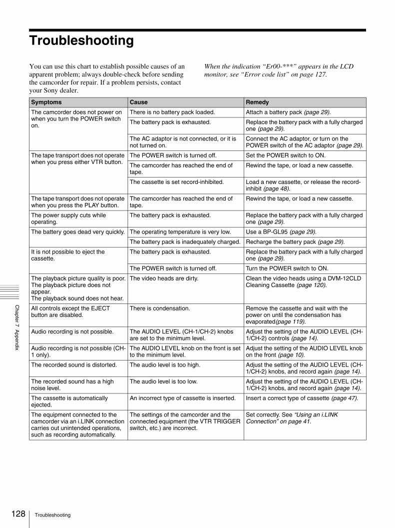
128
Chapter 7 A
ppendix
Troubleshooting
You can use this chart to establish possible causes of an apparent problem; always double-check before sending the camcorder for repair. If a problem persists, contact your Sony dealer.
When the indication “Er00-***” appears in the LCD monitor, see “Error code list” on page 127.
Symptoms Cause Remedy
The camcorder does not power on when you turn the POWER switch on.
There is no battery pack loaded. Attach a battery pack (page 29).
The battery pack is exhausted. Replace the battery pack with a fully charged one (page 29).
The AC adaptor is not connected, or it is not turned on.
Connect the AC adaptor, or turn on the POWER switch of the AC adaptor (page 29).
The tape transport does not operate when you press either VTR button.
The POWER switch is turned off. Set the POWER switch to ON.
The camcorder has reached the end of tape.
Rewind the tape, or load a new cassette.
The cassette is set record-inhibited. Load a new cassette, or release the record-inhibit (page 48).
The tape transport does not operate when you press the PLAY button.
The camcorder has reached the end of tape.
Rewind the tape, or load a new cassette.
The power supply cuts while operating.
The battery pack is exhausted. Replace the battery pack with a fully charged one (page 29).
The battery goes dead very quickly. The operating temperature is very low. Use a BP-GL95 (page 29).
The battery pack is inadequately charged. Recharge the battery pack (page 29).
It is not possible to eject the cassette.
The battery pack is exhausted. Replace the battery pack with a fully charged one (page 29).
The POWER switch is turned off. Turn the POWER switch to ON.
The playback picture quality is poor.The playback picture does not appear. The playback sound does not hear.
The video heads are dirty. Clean the video heads using a DVM-12CLD Cleaning Cassette (page 120).
All controls except the EJECT button are disabled.
There is condensation. Remove the cassette and wait with the power on until the condensation has evaporated(page 119).
Audio recording is not possible. The AUDIO LEVEL (CH-1/CH-2) knobs are set to the minimum level.
Adjust the setting of the AUDIO LEVEL (CH-1/CH-2) controls (page 14).
Audio recording is not possible (CH-1 only).
The AUDIO LEVEL knob on the front is set to the minimum level.
Adjust the setting of the AUDIO LEVEL knob on the front (page 10).
The recorded sound is distorted. The audio level is too high. Adjust the setting of the AUDIO LEVEL (CH-1/CH-2) knobs, and record again (page 14).
The recorded sound has a high noise level.
The audio level is too low. Adjust the setting of the AUDIO LEVEL (CH-1/CH-2) knobs, and record again (page 14).
The cassette is automatically ejected.
An incorrect type of cassette is inserted. Insert a correct type of cassette (page 47).
The equipment connected to the camcorder via an i.LINK connection carries out unintended operations, such as recording automatically.
The settings of the camcorder and the connected equipment (the VTR TRIGGER switch, etc.) are incorrect.
Set correctly. See “Using an i.LINK Connection” on page 41.
Troubleshooting
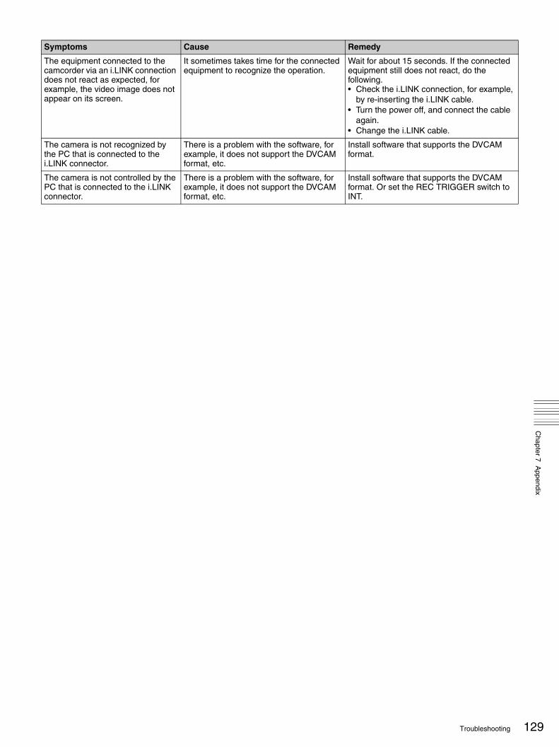
Chapter 7 A
ppendix
The equipment connected to the camcorder via an i.LINK connection does not react as expected, for example, the video image does not appear on its screen.
It sometimes takes time for the connected equipment to recognize the operation.
Wait for about 15 seconds. If the connected equipment still does not react, do the following.• Check the i.LINK connection, for example,
by re-inserting the i.LINK cable.• Turn the power off, and connect the cable
again.• Change the i.LINK cable.
The camera is not recognized by the PC that is connected to the i.LINK connector.
There is a problem with the software, for example, it does not support the DVCAM format, etc.
Install software that supports the DVCAM format.
The camera is not controlled by the PC that is connected to the i.LINK connector.
There is a problem with the software, for example, it does not support the DVCAM format, etc.
Install software that supports the DVCAM format. Or set the REC TRIGGER switch to INT.
Symptoms Cause Remedy
129Troubleshooting

130
Chapter 7 A
ppendix
Specifications
GeneralPower voltage 12 V DC +5.0/–1.0 VPower consumption
Approx. 17 W (with 12 V DC supply, when recording with the LCD monitor off)
Operating temperature0°C to +40°C (32°F to 104°F)
Storage temperature–20°C to +60°C (–4°F to +140°F)
Recording formatDVCAM, DV-SP
Continuous operating timeApprox. 300 min. (with BP-GL95)
Mass Approx. 3.9 kg (8 lb 10 oz) (main body only)
Approx. 6.5 kg (14 lb 5 oz) (with viewfinder, microphone, tape, BP-GL65 Battery Pack, and VCL-917BY Zoom Lens)
Dimensions
Supplied accessoriesVCL-917BY Zoom Lens (1) (supplied
with DSR-400K/400PK only)DXF-801 Viewfinder (1)Microphone (1)Wind screen (1)Shoulder strap (1)VCT-U14 Tripod Adaptor (1)Lens mount cap (1)Flange focal length adjustment test chart
(1)Operating Instructions
English version (1)Japanese version (1)CD-ROM manual (1)
Video Camera Section
GeneralImager 2/3-inch type, Power HAD EX CCD
Total picture elements1038 (H) × 1008 (V) (DSR-400/450WS), or 1038 (H) × 1188 (V) (DSR-400P/450WSP)
Effective picture elements980 (H) × 988 (V) (DSR-400/450WS), or 980 (H) × 1064 (V) (DSR-400P/450WSP)
Imager ConfigurationRGB 3 CCDs
Spectral systemF1.4 prism system (with quartz filter)
Built-in filter ND filter1: Clear2: 1/4 ND3: 1/16 ND4: 1/64 ND
Lens mount 2/3-inch 48 bayonet mountSensitivity F11 standard (89.9% reflection chart,
2000 lx)Minimum illumination
0.51x (at F1.4, +36 dB gain)Video S/N ratio 65 dB (Y-typical) (DSR-400/450WS), or
63 dB (Y-typical) (DSR-400P/450WSP)
Modulation DSR-450WS/450WSP: 850 TV lines (4:3 mode), 800 TV lines (16:9 mode)
DSR-400/400P: 920 TV linesRegistration 0.05% or less for entire screen area
(excluding distortion due to lens)Geometric distortion
None identified (excluding distortion due to lens)
Smear –140 dB (Y-typical)LCD monitor Picture: 6.3 cm (2 1/2 inches) in opposite
angle (2.5 type)Pixel resolution: 214,000 pixels (964
wide × 222 high)Effective picture elements: more than
99.99%
ViewfinderCRT 1.5-inch monochromeIndicator REC/TALLY (× 2), BATT, SHUTTER,
GAIN UPHorizontal resolution
600 TV linesPower voltage 12 V DCPower consumption
2.4 WMass Approx. 620 g (1 lb 6 oz)Maximum dimensions
241 × 91 × 203 mm (9 1/2 × 3 5/8 × 8 inch) (w/h/d)
in mm (inches)
146 (5 3/4)
215 (8 1/2)
268 (10 5/8)
328 (13)
Specifications
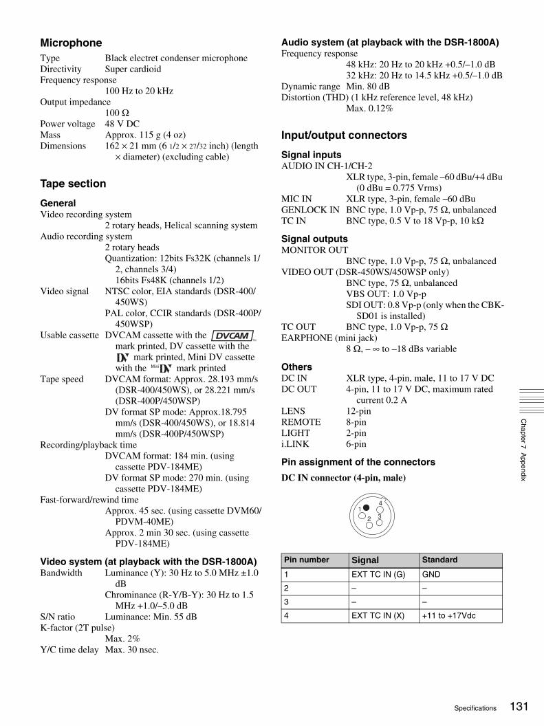
Chapter 7 A
ppendix
MicrophoneType Black electret condenser microphoneDirectivity Super cardioidFrequency response
100 Hz to 20 kHzOutput impedance
100 ΩPower voltage 48 V DCMass Approx. 115 g (4 oz)Dimensions 162 × 21 mm (6 1/2 × 27/32 inch) (length
× diameter) (excluding cable)
Tape section
GeneralVideo recording system
2 rotary heads, Helical scanning systemAudio recording system
2 rotary headsQuantization: 12bits Fs32K (channels 1/
2, channels 3/4)16bits Fs48K (channels 1/2)
Video signal NTSC color, EIA standards (DSR-400/450WS)
PAL color, CCIR standards (DSR-400P/450WSP)
Usable cassette DVCAM cassette with the mark printed, DV cassette with the
mark printed, Mini DV cassette with the mark printed
Tape speed DVCAM format: Approx. 28.193 mm/s (DSR-400/450WS), or 28.221 mm/s (DSR-400P/450WSP)
DV format SP mode: Approx.18.795 mm/s (DSR-400/450WS), or 18.814 mm/s (DSR-400P/450WSP)
Recording/playback timeDVCAM format: 184 min. (using
cassette PDV-184ME)DV format SP mode: 270 min. (using
cassette PDV-184ME)Fast-forward/rewind time
Approx. 45 sec. (using cassette DVM60/PDVM-40ME)
Approx. 2 min 30 sec. (using cassette PDV-184ME)
Video system (at playback with the DSR-1800A)Bandwidth Luminance (Y): 30 Hz to 5.0 MHz ±1.0
dBChrominance (R-Y/B-Y): 30 Hz to 1.5
MHz +1.0/–5.0 dBS/N ratio Luminance: Min. 55 dBK-factor (2T pulse)
Max. 2%Y/C time delay Max. 30 nsec.
Audio system (at playback with the DSR-1800A)Frequency response
48 kHz: 20 Hz to 20 kHz +0.5/–1.0 dB32 kHz: 20 Hz to 14.5 kHz +0.5/–1.0 dB
Dynamic range Min. 80 dBDistortion (THD) (1 kHz reference level, 48 kHz)
Max. 0.12%
Input/output connectors
Signal inputsAUDIO IN CH-1/CH-2
XLR type, 3-pin, female –60 dBu/+4 dBu (0 dBu = 0.775 Vrms)
MIC IN XLR type, 3-pin, female –60 dBuGENLOCK IN BNC type, 1.0 Vp-p, 75 Ω, unbalancedTC IN BNC type, 0.5 V to 18 Vp-p, 10 kΩ
Signal outputsMONITOR OUT
BNC type, 1.0 Vp-p, 75 Ω, unbalancedVIDEO OUT (DSR-450WS/450WSP only)
BNC type, 75 Ω, unbalancedVBS OUT: 1.0 Vp-pSDI OUT: 0.8 Vp-p (only when the CBK-
SD01 is installed)TC OUT BNC type, 1.0 Vp-p, 75 ΩEARPHONE (mini jack)
8 Ω, – ∞ to –18 dBs variable
OthersDC IN XLR type, 4-pin, male, 11 to 17 V DCDC OUT 4-pin, 11 to 17 V DC, maximum rated
current 0.2 ALENS 12-pinREMOTE 8-pinLIGHT 2-pini.LINK 6-pin
Pin assignment of the connectors
DC IN connector (4-pin, male)
Pin number Signal Standard
1 EXT TC IN (G) GND
2 – –
3 – –
4 EXT TC IN (X) +11 to +17Vdc
1
2 3
4
131Specifications

132
Chapter 7 A
ppendix
AUDIO IN CH-1/CH-2 connector (3-pin, female)
Related ProductsThere is a range of Sony products available to meet every conceivable video shooting requirement. For details, consult your Sony sales representative or supplier.
Power supply and related equipmentBP- GL65/GL95/L60S Battery PackBC-M50/M150 Battery ChargerAC-550 AC AdaptorAC-DN10 AC Adaptor
Equipment for remote controlRM-B150/B750 Remote Control Unit (can be installed to
the DSR-450WS/450WSP only)
“Memory Stick”MSH-32 (32 MB)MSH-64 (64 MB)MSH-128 (128 MB)
Audio equipmentECM-670/672 MicrophoneCAC-12 Microphone HolderWRR-855 UHF Synthesized Tuner UnitWRR-861/862 UHF Portable TunerWRT-822/824 UHF TransmitterWRR Tuner Fitting (service part number: A-8278-057-A)DMX-P01 Portable Digital Mixer
For Audio equipment described above, confirm whether the connector is male or female and the number of pins on the connector.
The audio input connectors of the camcorder are female and 3-pin. A converting adaptor may be required.
Studio equipmentDXF-51 5-inch Viewfinder (monochrome)
Extension boards (DSR-450WS/450WSP only)CBK-SD01 SDI Output BoardCBK-SC01 Composite Input Board
Cables and miscellaneousi.LINK cable (DV connecting cable)
CCFD-3L (6-pin y 4-pin, 3.5m)CCF-3L (6-pin y 6-pin, 3.5m)
LC-H300 Hard Carrying CaseLC-DS300SFT Soft Carrying CaseLCR-1 Rain Cover
Design and specifications are subject to change without notice.
Pin number Signal Standard
1 MIC IN (G) GND
2 MIC IN (X) –60dBuWhen ZI is equal to or more than 3kΩ/+4dBu, 10kΩBALANCED
3 MIC IN (Y)
32 1
Specifications

Chapter 7 A
ppendix
Chart of Optional Components and Accessories
For DSR-400/400P
* Optional accessory shoe kit is required for fitting. For details, consult your Sony dealer.
EC-0.5C2/0.3C2Microphone Cable
ECM-670/672 and C-74Microphone
CAC-12 Microphone Holder
DXF-51/51CE *5-inch Viewfinder
DSR-400/400P
VCT-U14 Tripod Adaptor
Tripod
LMD seriesLCD Monitor
LC-DS300SFTSoft Carrying Case
LC-H300Carrying Case
LCR-1 Rain cover
NTSC: WRR-855BPAL: WRR-588A/B UHF Synthesized Tuner
AC-550AC Adaptor
BP-GL65/GL95/L60SBattery Pack
DSR-50/50PDigital Videocassette Recorder
DSR-1500A/1600A/1800A/2000ADigital Videocassette Recorder
DVCAM mini size cassette tape
DVCAM standard size cassette tape
BC-M150Battery Charger
BC-M50Battery Charger
CA-WR855Camera Adaptor
AC-DN2B/AC-DN10AC Adaptor
133Chart of Optional Components and Accessories

134
Chapter 7 A
ppendix
For DSR-450WS/450WSP
* Optional accessory shoe kit is required for fitting. For details, consult your Sony dealer.
EC-0.5C2/0.3C2Microphone Cable
ECM-670/672 and C-74Microphone
CAC-12 Microphone Holder
DXF-51/51CE * 5-inch Viewfinder
CBK-SC01Analog Composite Input Board
DSR-450WS/450WSP
RM-B150/B750Remote Control Unit
VCT-U14 Tripod Adaptor
Tripod
LMD seriesLCD Monitor
LC-DS300SFTSoft Carrying Case
LC-H300Carrying Case
LCR-1 Rain cover
NTSC: WRR-855BPAL: WRR-588A/B UHF Synthesized Tuner
AC-550AC Adaptor
BP-GL65/GL95/L60SBattery Pack
DSR-50/50PDigital Videocassette Recorder
DSR-1500A/1600A/1800A/2000ADigital Videocassette Recorder
DVCAM mini size cassette tape
DVCAM standard size cassette tape
BC-M150Battery Charger
BC-M50Battery Charger
CA-WR855Camera Adaptor
AC-DN2B/AC-DN10AC Adaptor
CBK-SD01SDI Output Board
Chart of Optional Components and Accessories

Chapter 7 A
ppendix
Glossary
ATWAuto Tracing White balance. The white balance is automatically adjusted for the lighting conditions during shooting.
Bayonet typeA type of lens mount. The lens can be inserted into the lens mount and fixed in place by rotating a ring.
Black balanceTo balance the black level of the R, G, and B signals so that black has no color.
CCDAbbreviation for charge-coupled device. A semiconductor used in place of a camera tube. The CCD converts light into electrical charge, and outputs the electrical charge in the form of varying voltages.
Center markerA cross on the viewfinder screen that indicates the center of an image.
Color bar signalsTest signals displayed on the screen as multicolored vertical stripes. Used for adjustment of hue, and saturation of a video camera and video monitor.
Color conversion filter (CC filter)A filter that converts the color temperature to a reference value so the same picture tone is obtained in different lighting conditions.
Color temperatureThe color quality of light, expressed in Kelvin (K).
Composite video signalA signal that consists of video (luminance and color sub carrier), sync (horizontal and vertical), and color burst signals.
CTLAbbreviation for control signal. A signal that you can count to determine the number of frames, and therefore the tape's running time. It is
used mainly to adjust the tracking position of video heads, and to achieve time code continuity when recording continuously. This signal is recorded in a longitudinal tape track.
DCCAbbreviation for dynamic contrast control. In a high contrast environment, this function compresses the high light signal by adjusting the knee point automatically, allowing you to take clear pictures in a dynamic range.
Drop frame modeSMPTE time code runs at 30 frames/second, while the NTSC color television system runs at about 29.97 frames/second. Drop frame mode adjusts the running of time code to eliminate the discrepancy between time code value and actual time by dropping two frames from the time code value at the beginning of each minute except every tenth minute.
DrumA metal cylinder to which the video heads are attached. During recording and playback, the drum rotates at high speed in synchronization with a control signal.
EBUAbbreviation for European Broadcasting Union. A professional broadcasting establishment in Europe.
EXT TC (External time code)A time code input from external equipment together with audio data. It corresponds to the conventional time code recorded on tape based media. Instead the EXT TC is usually used to record time codes and audio signals that are played back by equipment that is not synchronized with the reference video signal.
FfSee “Flange focal length”.
Flange focal lengthThe length between the objective lens and the surface of the imager.
FlareThe loss of contrast in an image caused by unnecessary light that strays into the image plane.
FlickerRepeated changes in screen brightness caused by an interference between the camera's scanning and the lighting conditions.
GENLOCKA state in which devices are locked to a signal output by a sync generator. Genlock allows multiple devices to operate in synchronization.
HADAbbreviation for hole-accumulated diode. A CCD sensor structure designed to suppress certain types ofnoise inherent to CCDs.
Head drumSee “Drum”.
Horizontal resolutionThe horizontal resolution of the screen, which is expressed as the number of vertical lines distinguishable when shooting a test chart.
i.LINKAnother name for the IEEE1394-1995 standards and their revisions. XDCAM uses the i.LINK interface to transfer DV streams by the AV/C protocol, and toread and write MPEG IMX and DVCAM data files by FAM (File Access Mode).
Interlaced scan modeA scanning method in which odd rows fields are read alternately with even rows. (Odd-row fields and evenrow fields contain images from different times.)
ND filterAbbreviation for neutral density filter. A filter that reduces the amount of incident light equally across the entire visible wavelength range without affecting color.
Non-drop frame modeA mode of advancing time code which ignores the difference in frame values between real time and the time
135Glossary

136
Chapter 7 A
ppendix
code. Using this mode produces a difference of approximately 86 seconds per day between real time and time code, which causes problems when editing programs in units of seconds using the number of frames as a reference.
NTSCAbbreviation for National Television System Committee. NTSC is a color TV broadcasting system adopted mainly in North American countries, and in parts of Asia and Central and South America.
PALAbbreviation for Phase Alternating Line.PAL is a color TV broadcasting system developed by Telefunken GmbH of Germany. This system is adopted mainly in European countries, in Australia, and in parts of Asia and South America.
Progressive scan modeA scanning method in which odd rows and even rows are read at the same time. Also called full-screen scanning.
Reference video signalA video signal that contains a sync signal or sync and burst signals, used as a reference for synchronization of video equipment.
Return videoVideo signals that are sent back from a VTR to a camera or from a control console to a camera so that a camera operator can verify the recorded/selected video signals.
Sampling frequencyA method used to sample an analog signal so that it can be represented digitally. The higher the sampling frequency is, the more accurately the high-frequency analog signal can be represented.
SDISerial Digital Interface. An interface standardized as SMPTE 259M which enables the transmission of an uncompressed digital component stream.
ServoA mechanism that controls the number and phase of revolutions of the head drum, capstan, or reel tables. The servo mechanism allows recording and playback of the video signal without guard band noise. The reference signal of the servo control is normally a vertical sync signal.
Shot dataData recorded, while shooting, in the color bars, the user bits data of VITC, and so forth. Includes the model name, serial number, date, time, shot number, and ID1 to ID4.
Shutter speedThe time that the shutter is open. Slow shutter speeds give bright images, but motion resolution is lower.
SMPTESociety of Motion Picture and Television Engineers, a professional association established in the U.S.A. mainly for the purpose of setting forth motion picture and television engineering standards.
Stand-by off modeA mode in which the head drum is stationary and the tape is slack. It means that the VTR is not ready for immediate recording or playback. It does not mean that the tape or video heads are damaged.
Stand-by on modeA mode in which the head drum rotates with the tape wrapped around it. It means that the VTR is ready for recording or playback. The VTR comes into Stand-by off mode in a settled time not to damage tape and video head.
SuperimposeA procedure you use to put one picture (or character) over another so that both can be seen at the same time.
Time codeA digital signal recorded on the videotape that supplies information such as the hour, minute, second and frame number of each frame. There are two kinds of recorded signal:
longitudinal time code (LTC) and vertical interval time code (VITC).
Time code synchronizationTo synchronize the built-in time code generator of video equipment to an external time code.
Time dataTime information that is generated by a time code generator or read by a time code reader.
User's bitsA 32-bit section of time code in which you can record desired information such as the year, month, date and reel numbers.
VBSAbbreviation for video-burst-sync. A composite signal consisting of a video signal, a burst signal, and a sync signal.
VITCAbbreviation for vertical interval time code. A time code recorded on tape with video signals and inserted in the vertical blanking interval of video signals.The VTR can read this time code even in still mode.
White balanceThe adjustment of red, green and blue signal levels so that white objects are reproduced as true white.
White shadingA phenomenon whereby the upper and lower portions of the white object that you are shooting appear magenta or green, while the central portion of the image appears white.
Zebra patternStriped patterns that appear in the viewfinder to indicate areas of the picture where the video level is about 70 IRE units or 490 mV.
ZoomTo gradually change the field of view of a camera lens from wide to narrow angle (zoom in) or narrow to wide angle (zoom out).
Glossary
Chapter 7 A
ppendix
Index
Symbols* (Asterisk indicator) 22
Numerics16:9 mode recording indicator 2216:9/4:3 mode indicator 2324P mode 1085600 indicator 235600K button 10
AAC adaptor 29Accessory shoe 15ALARM knob 11ALL FILE page 89Analog composite signals 64Arrow key 14ASSIGN 1/2 switches 10ASSIGN 3/4 switches 15Assigning functions to ASSIGN
switches 106Attaching the microphone 34Attaching the video light 33Attachment shoe for large
viewfinder 16ATW 11AUDIO adjustment cover 13Audio format 23AUDIO IN CH-1/CH-2 connectors 18AUDIO IN input selection
switches 18AUDIO IN switches 15Audio input
Using an external microphone 34Using the supplied
microphone 34Audio level
Adjusting 57Indicator 22
AUDIO LEVEL controls (side) 14Audio level indicators 23AUDIO LEVEL knob (front) 10AUDIO OUT CH-1/CH-2
connectors 18AUDIO page 86AUDIO SELECT switches 14AUTO IRIS page 78AUTO IRIS 2 page 87AUTO SHADING page 88AUTO W/B BAL switch 9Auto-check function 120
Automatic irissetting 55Window 56
BBack space editing 61BATT indicator 21Battery attachment interface 17Battery capacity indicator 24Battery pack
Attaching 29Detaching 29Operation time 29
BATTERY page 85Black balance
Adjusting 50BLACK GAMMA page 81BLACK SHADING page 85BLACK/FLARE page 80BRIGHT control 21Built-in speaker 13
CCAMERA STATUS window 102Cassette
Compatibility of DVCAM and DV formats 48
Ejecting 45Inserting 45Inserting a mini-size cassette 45Usable cassettes 47
Cassette lid 16CD-ROM manual 25CLK 25CM indicator 23CNT 25Color temperature
Indicator 22Setting 104
Compatibility of DVCAM and DV formats 48
Connecting line input audio equipment 37
CONTRAST control 20Controlling the camcorder from a non-
linear editing system 43Correcting skin detail 60
DDAT 25Date/time
Indicator 23Setting 105
DC IN / battery voltage or remaining capacity 22
DC IN connector 17
DC OUT 12 V connector 18DCC (Dynamic Contrast Control) 11DCC ADJUST page 86DETAIL 1 page 82DETAIL 2 page 82DETAIL 3 page 82DEV STATUS 1 page 91DEV STATUS 2 page 92DIAGNOSIS menu 91DISP SEL button 12DISPLAY button 12DISPLAY switch 21DVCAM cassettes 47
EEARPHONE jack 13ECS 53EDIT SEARCH + FWD/- REV
buttons 13Edit search function 62E-E 13EJECT switch 16EVS 53EXT/IV indicator 22Extender 22External synchronization indicator 23Eyepiece focusing knob 20Eyepiece release catch 21
FF FWD button and indicator 13F.f adjustment ring 19F.f fixing knob 19Features 7FILE menu 88Filter indicator 23FILTER selector 9
Setting and examples of shooting conditions 9
Fitting for optional microphone holder 16
Flange focal length 28Flicker 50Focal servo module connector 19Focus ring 19FORMAT page 79FRONT MIC LOW CUT switch 15F-RUN/SET/R-RUN switch 14FUNCTION 1 page 76FUNCTION 2 page 76FUNCTION 3 page 87
137

138
Chapter 7 A
ppendix
GGain
Indicator 22Setting values for the GAIN
selector positions 103GAIN SW page 77GAIN switch 11GAIN UP indicator 21GAMMA page 81GENLOCK IN connector 16GENLOCK page 88
HHold indicator 23HOURS METER page 91
II (interlace scan) mode 108i.LINK
Checking the playback image recorded on an external VTR 42
Connecting 41Making backup of recording
image 41Settings required for an i.LINK
connection 41Using the camcorder as a
feeder 42i.LINK CTL setting 41i.LINK DV OUT connector 8, 18, 41ID number 23Instant automatic iris adjustment
button 19Interval rec 63
INTERVAL TIME 63REC TIME 63Settings before shooting 63Shooting 63
Iris 55Iris ring 19Iris selector 19Iris sensitivity 56Iris sensitivity trimmer 56Iris setting/auto iris override 22
KKNEE page 81
LLCD button 12LCD monitor 11, 12
Display 23Status display 98
LENS connector 9LENS FILE page 79LENS FILE 1 page 90LENS FILE 2 page 90LENS FILE 3 page 90Lens locking lever 10Lens mount 9Lens mount cap 9LIGHT connector 16LIGHT switch 10, 20Lithium battery
Attaching and Replacing 27Service life 27Warning indicator 24
Lithium battery compartment 14LOW KEY SAT page 84
MMACRO ring 20MACRO selector 19MAINTENANCE menu 84MARKER 1 page 77MARKER 2 page 77“Memory Stick” 123
Displaying a file-related menu page 117
Handling 109Inserting 109Protecting saved data 110Removing 109
MEMORY STICK page 90“Memory Stick” slot 18, 109Menu
Adjustments and settings 103Basic operations 93DIAGNOSIS menu 91Displaying 93Ending 93FILE menu 88MAINTENANCE menu 84OPERATION menu 75Organization 66PAINT menu 80TOP menu 73
MENU knob 10MENU switch 11MIC IN connector 16Model name and serial number
indicators 23MONITOR knob 11MONITOR OUT CHARACTER
switch 14MONITOR OUT connector 16MONITOR OUT page 75MONITOR SELECT switch 14Motorized zoom lever 19Mounting the lens 28
MTX LINEAR page 83MTX MULTI page 83
NND COMP page 88Non drop-frame indicator 23
OOFFSET WHT page 78OPERATION menu 75Operation/error message display
area 22OPTION BOARD page 92OUTPUT page 75OUTPUT/DCC switch 11Overview 6
PPAINT menu 80PEAKING control 20PLAY button and indicator 13Playback
Indicator 23On the color video monitor 65Recording review 65
Power supplyPreparing 29
POWER switch 11Pre-lighting function 63PRESET WHT page 86PRESET/REGEN/CLOCK switch 14Product configurations 6PsF (progressive scan) mode 108
RREC button 9REC TRIGGER switch 15REC/SAVE switch 48REC/TALLY indicators 21Recording format
Indicator 22Selecting 49
Recording shot data superimposed on the color bars 101
Reference file 116REFERENCE page 89Remaining tape capacity 22REMOTE connector 18Remote control unit
Camcorder switch functions when connected 37
Connecting 37Paint adjustment when
connected 37RM-B150/B750 37
Chapter 7 A
ppendix
Using settings of the paint adjustment data stored in the “independent data region” even when you disconnect a remote control unit 39
RESET button 12RET button 19REW button and indicator 13RM-B150/B750 37
SScan mode 108Scene file
Loading 115Loading scene files from a
“Memory Stick” into the camcorder memory 116
Saving 113Setting the file ID 114
SCENE FILE page 84, 89Selecting the aspect ratio 107Selecting the display items 98Selecting the lens file 106Selecting the output signals 104SET STATUS page 78Setting change and adjustment
progress message display area 22Setting change confirmation/
adjustment progress messagesChanging the display mode 99
Setting the marker display 100Setting the shot ID 101Setup add 65Setup remove 64Shooting 46SHOT DISP page 78SHOT ID page 78Shoulder pad 17
Adjusting the position 32Shoulder strap
Fitting and removing 32Shoulder strap fitting 15SHT ENABLE page 79SHUTTER indicator 21Shutter mode 52Shutter speed 52
Indicator 22SHUTTER switch 10SKIN DETAIL page 82SLS 53, 54SOURCE SEL page 79Status confirmation windows
Disabling display 103Displaying 103
STOP button 13Stopper 20
SW STATUS page 80Synchronizing two or more
camcorders 44
TTALLY indicator 17, 21Tally lamp 21TALLY switch 17TALLY switch (viewfinder) 21TAPE indicator 13Tape indicator 16Tape remaining indicator 24TC IN connector 17TC OUT connector 17TCG 25TCR 25Time code
Indicator 23Making the time code consecutive
58Saving the actual time 58Setting 57Synchronizing 58
Time counter indicator 25TIME/DATE page 91Trigger mode 22Tripod
Fitting/removing 33
UUBG 25UBR 25User bit
Setting 58User file
Loading 112Saving 110Setting the file ID 111
USER FILE page 88USER FILE 2 page 88USER menu
Canceling setting 95Editing 95Moving to another page 95Returning to the standard
settings 95Setting 94
USER MENU CUSTOMIZE menuAdding a new page 95Adding/deleting/replacing
pages 97Resetting USER menu settings to
the standard settings 98
VV MODULATION page 83VF connector 9VF DISP 1 page 76VF DISP 2 page 77VF SETTING page 77Video format 23VIDEO OUT connector 18Viewfinder 20
Adjusting contrast and brightness 31
Adjusting the eyepiece focus 31Adjusting the outline emphasis 31Adjusting the position 30Attaching a 5-inch electronic
viewfinder 31Fitting the viewfinder 31Removing 31Setting 100Status display on the screen 98
Viewfinder connector 21Viewfinder fitting shoe 16Viewfinder front-to-back position
locking knob 15Viewfinder left-to-right positioning
ring 15VTR button 20VTR MODE page 86VTR operation indicators 21VTR STATUS window 102
WWARNING indicator 13Warning indicators 24WHITE BAL switch 11White balance
Adjusting 51Offset 105Saving in the scene file 114White balance memory
indicator 23WHITE page 80WHITE SHADING page 84Wireless microphone system
WRR-855 36WRR-861 36WRR-862 36
WRR connector 18
ZZEBRA button 10Zoom remote control connector 19Zoom ring 19ZOOM selector 19
139

Sony Corporation