inspection/adjustment uxv 500 - nazwa.plmotor-land.nazwa.pl/ksiazki_serwisowe/uxv500/03.pdfcheck the...
TRANSCRIPT

3. INSPECTION/ADJUSTMENT
3-0
UXV 500
3 __________________________________________________________________________________
__________________________________________________________________________________
__________________________________________________________________________________
INSPECTION/ADJUSTMENT__________________________________________________________________________________
SERVICE INFORMATION------------------------------------------------ 3- 1MAINTENANCE SCHEDULE-------------------------------------------- 3- 3FUEL LINE/THROTTLE OPERATION--------------------------------- 3- 4SPEED LIMITER/AIR CLEANER --------------------------------------- 3- 5AIR BOX FOR DRIVE BELT --------------------------------------------- 3- 7SECONDARY AIR SUPPLY SYSTEM --------------------------------- 3- 8SPARK PLUG---------------------------------------------------------------- 3- 9VALVE CLEARANCE ----------------------------------------------------- 3-11CARBURETOR IDLE SPEED -------------------------------------------- 3-12CLINDER COMPRESSION/ENGINE OIL ----------------------------- 3-13REAR DRIVE GEAR OIL ------------------------------------------------- 3-17FRONT DRIVE GEAR OIL------------------------------------------------ 3-18SPARK ARRESTER -------------------------------------------------------- 3-19DRIVE SHAFT BOOTS ---------------------------------------------------- 3-20DRIVE BELT/BRAKE PADS INSPECTION --------------------------- 3-21BRAKE FLUID INSPECTION/HEADLIGHT AIM ------------------- 3-22STEERING SYSTEM INSPECTION------------------------------------- 3-23TOE-IN ADJUSTMENT --------------------------------------------------- 3-24WHEELS/TIRES ------------------------------------------------------------ 3-25COOLING SYSTEM-------------------------------------------------------- 3-28PARKING BRAKE ADJUSTMENT ------------------------------------- 3-29
3

3. INSPECTION/ADJUSTMENT
3-1
UXV 500
SERVICE INFORMATION
GENERAL
! WARNING•Before running the engine, make sure that the working area is well-ventilated. Never run theengine in a closed area. The exhaust contains poisonous carbon monoxide gas which maycause death to people.•Gasoline is extremely flammable and is explosive under some conditions. The working areamust be well-ventilated and do not smoke or allow flames or sparks near the working area orfuel storage area.
SPECIFICATIONS
Throttle grip free play : 3~5 mm (0.12~0.2 in)
Spark plug gap : 0.6~0.7 mm (0.024~0.028 in)
Spark plug: Standard : CR7E (NGK)
Valve clearance : IN: 0.1 mm (0.004 in)EX: 0.1 mm (0.004 in)
Idle speed : 1500±100 rpm
Engine oil capacity At disassembly : 3.6 liter (3.17 lmp qt, 3.82 Us qt) At change : 3 liter (2.64 lmp qt, 3.18 Us qt) After draining and oil filter cartridge change: 3.2 liter (2.82 lmp qt, 3.39 Us qt)
Front drive gear oil Recommended oil: SAE 80~90 At disassembly: 270 cc (10.6 lmp oz, 10.1 Us oz) At change: 270 cc (10.6 lmp qt, 10.1 Us qt)
Rear drive gear oil Recommended oil: SAE 80~90 At disassembly: 250 cc (5.33 lmp oz, 5 Us oz) At change: 250 cc (4.63 lmp qt, 4.33 Us qt)
Cylinder compression: 15 kg/cm² (1500 kPa, 213 psi)
Ignition timing: 5°±1°/1500 rpm

3. INSPECTION/ADJUSTMENT
3-2
UXV 500
Tire pressure
1 RiderFront 0.7 kgf/cm² (10 psi)Rear 0.98 kgf/cm² (14 psi)
Tire size: Front : 25X8-12 Rear : 25X10-12
TORQUE VALUES Spark plug 1.2kgf-m (12 N-m, 8.6 lbf-ft) Tappet ADJ nut 0.9 kgf-m (9 N-m, 6.5 lbf-ft) Engine oil filter cap 1.5 kgf-m (15 N-m, 11 lbf-ft) Engine oil filter cartridge 1 kgf-m (10 N-m, 7.2 lbf-ft) Engine oil drain plug 2.5 kgf-m (25 N-m, 18 lbf-ft) Rear drive gear oil drain bolt 2 kgf-m (20 N-m, 15 lbf-ft) Rear drive gear oil level check bolt 2 kgf-m (20 N-m, 15 lbf-ft) Rear drive gear oil filler cap 1.5 kgf-m (15 N-m, 11 lbf-ft) Front drive gear oil drain bolt 3.2 kgf-m (32 N-m, 23 lbf-ft) Front drive gear oil filler cap 3.5 kgf-m (35 N-m, 25.5 lbf-ft) Front drive gear oil level check bolt 1 kgf-m (10 N-m, 7.2 lbf-ft) Tie-rod adjusting nut 3.5 kgf-m (35 N-m, 25.2 lbf-ft) Front wheel hub nut 7 kgf-m (70 N-m, 50 lbf-ft) Rear wheel hub nut 10 kgf-m (100 N-m, 72 lbf-ft)
SPECIAL TOOLSValve adjusting wrench A120E00036Oil cartridge wrench A120E00061
3. INSPECTION/ADJUSTMENT
3-3
UXV 500
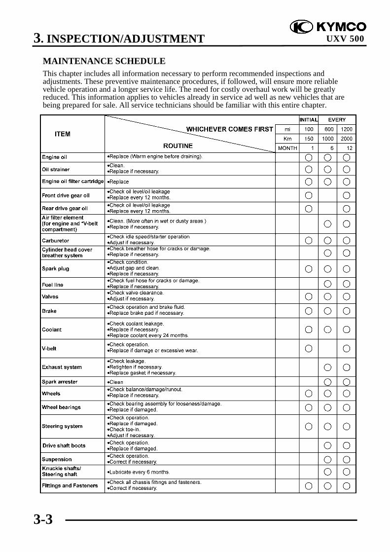
MAINTENANCE SCHEDULEThis chapter includes all information necessary to perform recommended inspections andadjustments. These preventive maintenance procedures, if followed, will ensure more reliablevehicle operation and a longer service life. The need for costly overhaul work will be greatlyreduced. This information applies to vehicles already in service ad well as new vehicles that arebeing prepared for sale. All service technicians should be familiar with this entire chapter.

3. INSPECTION/ADJUSTMENT
3-4
UXV 500
FUEL LINE
Check the fuel tubes and replace any parts,which show signs of deterioration, damageor leakage.
THROTTLE OPERATION
Check the throttle to swing for smoothmovement.Measure the throttle to swing free play.Free Play (A): 3~5 mm (0.12~0.2 in)
To adjust throttle free play:
1. Slide the rubber sleeve (1) back to exposethe throttle cable adjuster (2).
2. Loosen the lock nut (3), then turn theadjuster to obtain the correct free play.(3~5 mm or 0.12~0.2 in)
3. Tighten the lock nut and reinstall thesleeve.
Other checks:Check the throttle cable for kinks and signsof wear that could cause stretching orfailure. Lubricate the throttle cable with acommercially available lubricant to preventpremature wear and corrosion.
Fuel Filter
Fuel tubes
Do not smoke or allow flames or sparksin your working area.
*

3. INSPECTION/ADJUSTMENT
3-5
UXV 500
AIR CLEANER
AIR CLEANER REPLACEMENT
1. Remove the seat.2. Remove the center cover.3. Remove the six screws and remove the
air cleaner housing cover .
3. Loosen the screw and remove the aircleaner assembly from the air cleanerhousing.
4. Unscrew the clamp .
5. Remove the outer air cleaner (7).6. Remove the screw/washers (6) and
remove the air cleaner assembly from theair cleaner holder (8).
7. Remove the inner air cleaner (9) and aircleaner screen (10) from the air cleanerguide (11).
8. Remove the air cleaner screen from theinner air cleaner.

3. INSPECTION/ADJUSTMENT
3-6
UXV 500
CLEAN AIR FILTER ELEMENT
Wash the element gently, but throughly insolvent.
Squeeze the excess solvent out of theelement and let dry.
Apply the engine oil.Squeeze out the excess oil.
More frequent replacement is required whenriding in unusually dusty or rainy areas.
Use parts cleaning solvent only. Neveruse gasoline or low flash point solventswhich may lead to a
*
Do not twist or wring out the foamelement. This could damage the foammaterial.
*
The element should be wet but notdripping.
*

3. INSPECTION/ADJUSTMENT
3-7
UXV 500
AIR CLEANER HOUSING DRAIN
1. Remove the drain tube by removing theclip .
2. Drain the deposits.3. Reinstall the drain tube, securing it with
the clip.
AIR BOX FOR DRIVE BELT
To check the air box:Remove rider’s side seat.
Remove air hose.Check air box for drive belt
has obstruct or water. If has it. Clean or remove it.
Rear air box
Front air box

3. INSPECTION/ADJUSTMENT
3-8
UXV 500
SECONDARY AIR SUPPLYSYSTEM
This model is equipped with a built-insecondary air supply system. The pulsesecondary air supply system is located onthe cylinder head.The secondary air supply system introducesfiltered air into exhaust gases in the exhaustport. The secondary air is drawn into theexhaust port whenever there is negativepressure pulse in the exhaust system. Thischarged secondary air promotes burning ofthe unburned exhaust gases and changes aconsiderable amount of hydrocarbons andcarbon monoxide into relatively harmlesscarbon dioxide and water.
Check the AICV (air injection control valve)hoses between the AICV control solenoidvalve and cylinder head for deterioration,damage or loose connections. Make sure thehoses are not cracked.If the hoses show any signs of heat damage,inspect the AICV check valve in the AICVreed valve cover damage.
3. INSPECTION/ADJUSTMENT
3-9
UXV 500
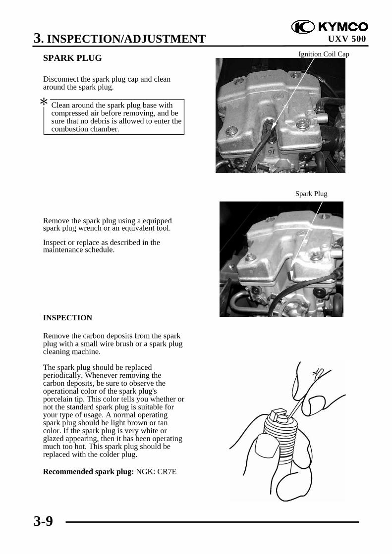
SPARK PLUG
Disconnect the spark plug cap and cleanaround the spark plug.
Remove the spark plug using a equippedspark plug wrench or an equivalent tool.
Inspect or replace as described in themaintenance schedule.
INSPECTION
Remove the carbon deposits from the sparkplug with a small wire brush or a spark plugcleaning machine.
The spark plug should be replacedperiodically. Whenever removing thecarbon deposits, be sure to observe theoperational color of the spark plug'sporcelain tip. This color tells you whether ornot the standard spark plug is suitable foryour type of usage. A normal operatingspark plug should be light brown or tancolor. If the spark plug is very white orglazed appearing, then it has been operatingmuch too hot. This spark plug should bereplaced with the colder plug.
Recommended spark plug: NGK: CR7E
Ignition Coil Cap
Spark Plug
Clean around the spark plug base withcompressed air before removing, and besure that no debris is allowed to enter thecombustion chamber.
*

3. INSPECTION/ADJUSTMENT
3-10
UXV 500
Measure the spark plug gap between thecenter and side electrodes with the feelergauge.If necessary, adjust the gap by bending theside electrode carefully.
Spark plug gap:
0.6-0.7 mm (0.024-0.028 in)
Install the spark plug in the cylinder headand hand tighten, then torque to thespecification.
Torque: 1.2 kgf-m (12 N-m, 8.6 lbf-ft)
Install the spark plug cap.
Install the removed parts in the reverseorder of removal.
0.6~0.7 mm

3. INSPECTION/ADJUSTMENT
3-11
UXV 500
VALVE CLEARANCE
To adjust:
Remove the right floorboard (refer to the“FRAME COVERS” section in the chapter2).Remove the cylinder head cover (refer tothe “CYLINDER HEAD COVERREMOVAL/INSTALLATION” section inthe chapter 8).
Remove the timing hole cap and O-ring.
Remove the recoil starter and O-rings (referto the “STARTER PULLEYREMOVAL/INSPECTION/INSTALLATION” section in the chapter8).
Turn the crankshaft clockwise and align the“T” mark on the flywheel with the indexmark on the right crankcase cover.
The punch marks on the camshaft shouldface upward as shown.
If the punch marks on the camshaft arefacing downward, turn the crankshaftclockwise one full turn (360°) and thepunch marks are facing upward.
Inspect and adjust the valve clearancewhile the engine is cold (Below35°C/95°F).
*
Crankshaft Hole Cap/O-ring
Timing Hole Cap
Punch Marks
“T” Mark

3. INSPECTION/ADJUSTMENT
3-12
UXV 500
Adjust by loosening the valve adjustingscrew lock-nut and turning the adjustingscrew until there is a slight drag on thethickness gauge.
Valve clearance (when cold):IN.: 0.1 mm (0.004 in)EX.: 0.1 mm (0.004 in)
Apply oil to the valve adjusting screw lock-nut threads and seating surface.Hold the adjusting screw and tighten thelock nut.
Special tool:Valve adjusting wrench A120E00036
Torque: 0.9 kgf-m (9 N-m, 6.5 lbf-ft)
After tightening the lock nut, recheck thevalve clearance.
Install the removed parts in the reverseorder of removal.
CARBURETOR IDLE SPEED
Warm up the engine before this operation.Start the engine and connect a tachometer.Turn the throttle stop screw to obtain thespecified idle speed.
Idle Speed: 1500±100 rpm
When the engine misses or run erratic,adjust the pilot screw (refer to the“CARBURETORDISASSEMBLY/INSPECTION/ASSEMBLY” section in the chapter 5).
Throttle Stop Screw
The engine must be warm for accurateidle speed inspection and adjustment.
*
Lock Nut
Wrench Thickness Gauge Valve Adjusting

3. INSPECTION/ADJUSTMENT
3-13
UXV 500
CYLINDER COMPRESSION
Warm up the engine before compressiontest.Remove the spark plug.Insert a compression gauge.Open the throttle valve fully and push thestarter button to test the compression.
Cylinder compression:15 kg/cm² (1500 kPa, 213 psi)
If the compression is low, check for thefollowing:- Leaky valves- Valve clearance too small- Leaking cylinder head gasket- Worn piston rings- Worn piston/cylinderIf the compression is high, it indicates thatcarbon deposits have accumulated on thecombustion chamber and the piston head.
ENGINE OILOIL LEVELPlace the machine on a level place.Warm up the engine for several minutes andstop it.
Check the oil level through the inspectionwindow.The oil level should be between themaximum (H) and minimum (L) marks. Ifthe level is low, add oil to raise it to theproper level.Recommended engine oil:KYMCO 4-stroke oil or equivalent motoroil API service classification: SJViscosity: SAE 5W50
Compression Gauge
Inspection WindowLower Level
Upper Level
Run the engine for 2~3 minutes andcheck the oil level after the engine isstopped for 2~3 minutes.
*
Other viscosities shown in the chart maybe used when the average temperature inyour riding area is within the indicatedrange.
*
3. INSPECTION/ADJUSTMENT
3-14
UXV 500
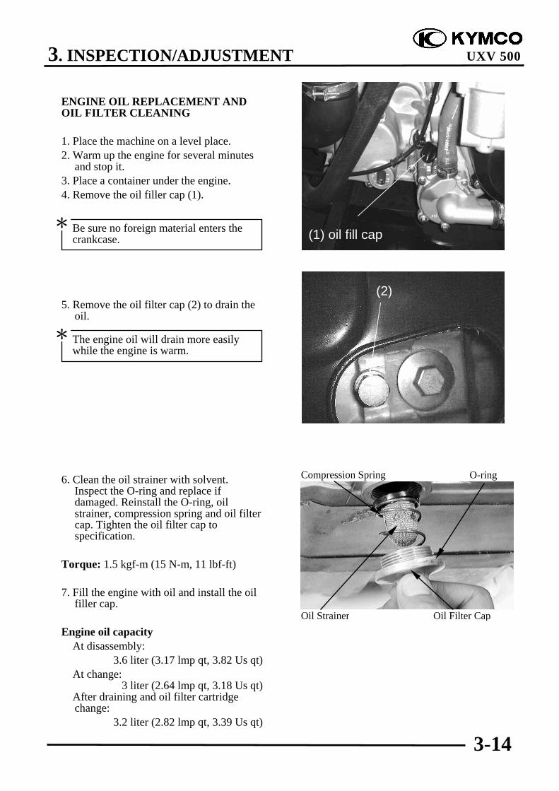
ENGINE OIL REPLACEMENT ANDOIL FILTER CLEANING
1. Place the machine on a level place.2. Warm up the engine for several minutes
and stop it.3. Place a container under the engine.4. Remove the oil filler cap (1).
5. Remove the oil filter cap (2) to drain theoil.
6. Clean the oil strainer with solvent.Inspect the O-ring and replace ifdamaged. Reinstall the O-ring, oilstrainer, compression spring and oil filtercap. Tighten the oil filter cap tospecification.
Torque: 1.5 kgf-m (15 N-m, 11 lbf-ft)
7. Fill the engine with oil and install the oilfiller cap.
Engine oil capacity At disassembly:
3.6 liter (3.17 lmp qt, 3.82 Us qt) At change:
3 liter (2.64 lmp qt, 3.18 Us qt) After draining and oil filter cartridge
change:3.2 liter (2.82 lmp qt, 3.39 Us qt)
O-ringCompression Spring
Oil Strainer Oil Filter Cap
Be sure no foreign material enters thecrankcase.
*
The engine oil will drain more easilywhile the engine is warm.
*
(1) oil fill cap
(2)

3. INSPECTION/ADJUSTMENT
3-15
UXV 500
ENGINE OIL REPLACEMENT (WITHOR WITHOUT OIL FILTERCARTRIDGE REPLACEMENT)
1. Place the machine on a level place.2. Warm up the engine for several minutes
and stop it.3. Place a container under the engine.4. Remove the oil fill cap (1).
5. Remove the drain plug (2) to drain theoil.
Be sure no foreign material enters thecrankcase.
*
The engine oil will drain more easilywhile the engine is warm.
*
(1) oil fill cap
(2)(2)

3. INSPECTION/ADJUSTMENT
3-16
UXV 500
6. Remove the oil filter cartridge (5) with anoil cartridge wrench.
Special tool:Oil cartridge wrench A120E00061
7. Apply a light coat of clean engine oil tothe O-ring (6) of the new oil filtercartridge.
9. Install the new oil filter cartridge with anoil cartridge wrench, and then tighten itto the specified torque.
Torque: 1 kgf-m (10 N-m, 7.2 lbf-ft)
10. Install right side cover.11. Reinstall the drain plug and tighten the
drain plug to the specified torque.
Torque: 2.5 kgf-m (25 N-m, 18 lbf-ft)
12. Add the specified amount ofrecommended engine oil, and theninstall the engine oil filler cap andtighten it.
Engine oil capacity At disassembly:
3.6 liter (3.17 lmp qt, 3.82 Us qt) At change:
3 liter (2.64 lmp qt, 3.18 Us qt) After draining and oil filter cartridge
change:3.2 liter (2.82 lmp qt, 3.39 Us qt)
Make sure the O-ring is seated properly.*
Be sure no foreign material enters thecrankcase.
*
(5)

3. INSPECTION/ADJUSTMENT
3-17
UXV 500
13. Start the engine and warm it up forseveral minutes. While warming up,check for oil leakage. If oil leakage isfound, turn the engine off immediatelyand check for the cause.
14. Turn the engine off, and then check theoil level through the inspection window(7) and correct it if necessary.
REAR DRIVE GEAR OIL
Change the oil in the rear drive gear casewhen specified by the MaintenanceSchedule. Change the oil with the rear drivegear case warm, and the UXV on levelground to assure complete and rapiddraining.
Rear drive gear oil replacement
1. To drain the oil, first place an oil drain panunder the oil drain plug (1).
3. Remove the oil filler cap (2), then removethe drain plug.
4. After the oil has completely drained,reinstall the drain plug.
Torque: 2 kgf-m (20 N-m, 15 lbf-ft)
5. Fill the gear case with the recommendedoil.Recommended oil: SAE 80~90Oil quantity: Periodic oil change:0.25 L
Remove the oil level check bolt (3).Make sure the oil level reaches the oillevel check hole.
(2)
(3)(1)

3. INSPECTION/ADJUSTMENT
3-18
UXV 500
6. Install the oil filler cap and oil levelcheck bolt.
Torque:Oil filler cap: 1.5 kgf-m (15 N-m, 12 lbf-ft)Oil level check bolt:
2 kgf-m (20 N-m, 15 lbf-ft)
7. Install the skid plate.
FRONT DRIVE GEAR OIL
Change the oil in the front drive gear casewhen specified by the MaintenanceSchedule. Change the oil with the frontdrive gear case warm, and the UXV on levelground to assure complete and rapiddraining.
Front drive gear oil replacement
1. To drain the oil, first place an oil drainpan under the oil drain plug (1).
2. Remove the oil filler bolt (2).
3. Remove the drain plug.
4. After the oil has completely drained,reinstall and tighten the drain plug to thespecified torque.
Torque: 3.2 kgf-m (32 N-m, 23 lbf-ft)
5. Fill the gear case with the recommendedoil.
Recommended oil: SAE 80-90Oil quantity: Periodic oil change:
0.27 L
Be sure no foreign material enters thecrankcase.
*
(2)
3. INSPECTION/ADJUSTMENT
3-19
UXV 500
. Remove the oil level check bolt (3). Makesure the oil level reaches the oil levelcheck hole.
6. Install and tighten the oil filler bolt to the specified torque.
Torque:Oil filler cap:
3.5 kgf-m (35 N-m, 25.5 lbf-ft)Oil level check bolt:
1 kgf-m (10 N-m, 7.2 lbf-ft)
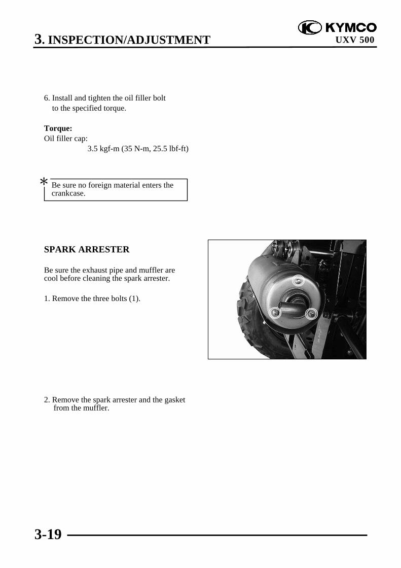
SPARK ARRESTER
Be sure the exhaust pipe and muffler arecool before cleaning the spark arrester.
1. Remove the three bolts (1).
2. Remove the spark arrester and the gasketfrom the muffler.
Be sure no foreign material enters thecrankcase.
*

3. INSPECTION/ADJUSTMENT
3-20
UXV 500
3. Use a brush to remove carbon depositsfrom the spark arrester screen. Be carefulto avoid damaging the spark arresterscreen. The spark arrester must be free ofbreaks and holes. Replace, if necessary.Check the gasket. Replace, if necessary.
4. Install the spark arrester and the gasket inthe muffler and tighten the three boltssecurely.
DRIVE SHAFT BOOTS
Check the protective boots for holes ortears.If any damage is found, have them replaced.

3. INSPECTION/ADJUSTMENT
3-21
UXV 500
DRIVE BELT
Remove the left crankcase cover (refer tothe “LEFT CRANKCASE COVERREMOVAL/INSTALLATION” section in thechapter 10).
Inspect the drive belt for cracks, scaling,chipping or excessive wear.Measure the V-belt width
Service limit (A): 30.8 mm (1.232 in)
Replace the drive belt if out of specification.
Refer to the “DRIVE PULLEY, DRIVEV-BELT AND DRIVEN PULLEYREMOVAL/INSPECTION/INSTALLATION” section in the chapter10 for removal/installation.
BRAKE PADS INSPECTION
A wear indicator is provided on each brake.The indicators allows checking of brakepads wear. Check the position of theindicator. If the indicator reaches the wearlimit line, to replace the pads.
Drive Belt
(A)

3. INSPECTION/ADJUSTMENT
3-22
UXV 500
BRAKE FLUID INSPECTION
Check if the fluid level is below the lowerlevel mark through the inspection window.
HEADLIGHT AIM
Turn the ignition switch ON and start theengine.Turn on the headlight switch.Adjust the headlight aim by turning theheadlight aim adjusting screws.
Inspection Window
Adjust Screws
(1) Lower level mark(2) Upper level mark
3. INSPECTION/ADJUSTMENT
3-23
UXV 500
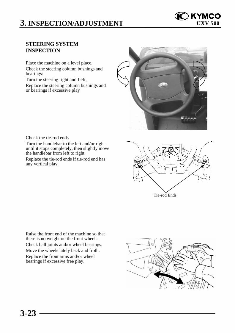
STEERING SYSTEMINSPECTION
Place the machine on a level place.Check the steering column bushings andbearings:Turn the steering right and Left,Replace the steering column bushings andor bearings if excessive play
Check the tie-rod endsTurn the handlebar to the left and/or rightuntil it stops completely, then slightly movethe handlebar from left to right.Replace the tie-rod ends if tie-rod end hasany vertical play.
Raise the front end of the machine so thatthere is no weight on the front wheels.Check ball joints and/or wheel bearings.Move the wheels lately back and froth.Replace the front arms and/or wheelbearings if excessive free play.
Tie-rod Ends
3. INSPECTION/ADJUSTMENT
3-24
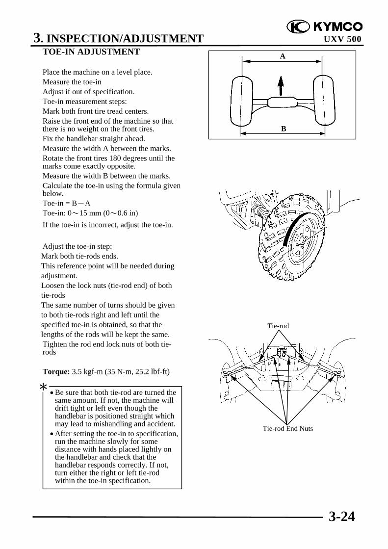
UXV 500TOE-IN ADJUSTMENT
Place the machine on a level place.Measure the toe-inAdjust if out of specification.Toe-in measurement steps:Mark both front tire tread centers.Raise the front end of the machine so thatthere is no weight on the front tires.Fix the handlebar straight ahead.Measure the width A between the marks.Rotate the front tires 180 degrees until themarks come exactly opposite.Measure the width B between the marks.Calculate the toe-in using the formula givenbelow.Toe-in = B-AToe-in: 0~15 mm (0~0.6 in)If the toe-in is incorrect, adjust the toe-in.
Adjust the toe-in step: Mark both tie-rods ends. This reference point will be needed during adjustment. Loosen the lock nuts (tie-rod end) of both tie-rods The same number of turns should be given to both tie-rods right and left until the specified toe-in is obtained, so that the lengths of the rods will be kept the same.
Tighten the rod end lock nuts of both tie-rods
Torque: 3.5 kgf-m (35 N-m, 25.2 lbf-ft)
•Be sure that both tie-rod are turned thesame amount. If not, the machine willdrift tight or left even though thehandlebar is positioned straight whichmay lead to mishandling and accident.
•After setting the toe-in to specification,run the machine slowly for somedistance with hands placed lightly onthe handlebar and check that thehandlebar responds correctly. If not,turn either the right or left tie-rodwithin the toe-in specification.
*
Tie-rod
Tie-rod End Nuts
A
B

3. INSPECTION/ADJUSTMENT
3-25
UXV 500
WHEELS/TIRES
Check the tires for cuts, imbedded nails orother damages.Check the tire pressure.
TIRE PRESSURE
1 Rider
Front 0.7kgf/cm² (10psi)
Rear 0.98 kgf/cm² (14 psi)
TIRE SIZEFront : 25X8-12Rear : 25X10-12
Check the front axle nut for looseness.
Front Axle Nut
Tire pressure should be checked whentires are cold.
*
The threads on both rod-end must be ofthe same length.
*

3. INSPECTION/ADJUSTMENT
3-26
UXV 500
Check the rear axle nut for looseness.If the axle nuts are loose, tighten them to thespecified torque.
Torque:Front: 7 kgf-m (70 N-m, 50 lbf-ft)Rear: 10 kgf-m (100 N-m, 72 lbf-ft)
Inspect the tire surfaces.Replace if wear or damage.
Tire wear limit: 4 mm (0.16 in)
WHEEL INSPECTION
Inspect the wheel.Replace if damage or bendsAlways balance the wheel when a tire orwheel has been changed or replaced.
Rear Axle Nut
•Never attempt even small repairs to thewheel.
•Ride conservatively after installing atire to allow it to seat itself properly onthe rim.
*
It is dangerous to ride with a worn outtire. When a tire wear is out ofspecification, replace the tireimmediately.
*
3. INSPECTION/ADJUSTMENT
3-27
UXV 500
COOLING SYSTEM
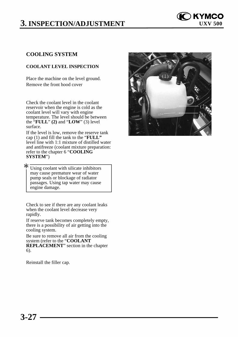
COOLANT LEVEL INSPECTION
Place the machine on the level ground.Remove the front hood cover
Check the coolant level in the coolantreservoir when the engine is cold as thecoolant level will vary with enginetemperature. The level should be betweenthe “FULL” (2) and “LOW” (3) levelsurface.If the level is low, remove the reserve tankcap (1) and fill the tank to the “FULL”level line with 1:1 mixture of distilled waterand antifreeze (coolant mixture preparation:refer to the chapter 6 “COOLINGSYSTEM”)
Check to see if there are any coolant leakswhen the coolant level decrease veryrapidly.If reserve tank becomes completely empty,there is a possibility of air getting into thecooling system.Be sure to remove all air from the coolingsystem (refer to the “COOLANTREPLACEMENT” section in the chapter6).
Reinstall the filler cap.
Using coolant with silicate inhibitorsmay cause premature wear of waterpump seals or blockage of radiatorpassages. Using tap water may causeengine damage.
*
(1)
(2)
(3)
3. INSPECTION/ADJUSTMENT
3-28
UXV 500
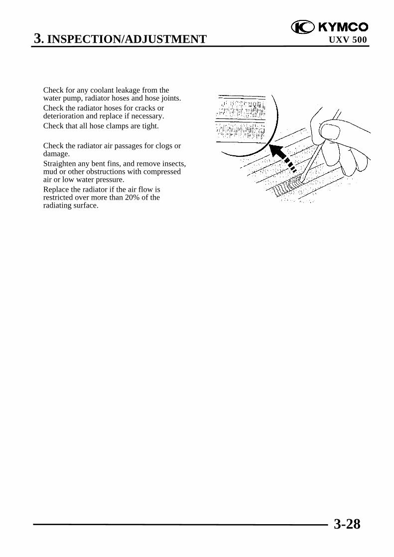
Check for any coolant leakage from thewater pump, radiator hoses and hose joints.Check the radiator hoses for cracks ordeterioration and replace if necessary.Check that all hose clamps are tight.
Check the radiator air passages for clogs ordamage.Straighten any bent fins, and remove insects,mud or other obstructions with compressedair or low water pressure.Replace the radiator if the air flow isrestricted over more than 20% of theradiating surface.
3. INSPECTION/ADJUSTMENT
3-29
UXV 500
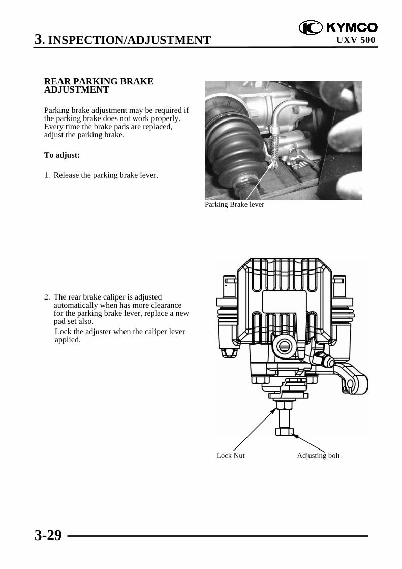
REAR PARKING BRAKEADJUSTMENT
Parking brake adjustment may be required ifthe parking brake does not work properly.Every time the brake pads are replaced,adjust the parking brake.
To adjust:
1. Release the parking brake lever.
2. The rear brake caliper is adjustedautomatically when has more clearancefor the parking brake lever, replace a newpad set also.
Lock the adjuster when the caliper leverapplied.
Parking Brake lever
Lock Nut Adjusting bolt

3. INSPECTION/ADJUSTMENT
3-30
UXV 500
3. Loosen the lock nut and adjuster on thecable.
4. Turn the adjuster until the caliper lever isabout to rotate then Tighten the lock nut.
Parking brake cable end length:L: 53 ± 2 mm (2.12 ± 0.08 in)
5. Slowly turn the adjusting bolt on thecaliper clockwise until resistance is felt,then turn adjusting bolt 1/8counterclockwise.
6. Tighten the lock nut to the specifiedtorque while hold the adjusting bolt.
Torque:1.6 kgf-m (16 N-m, 11.52 lbf-ft)
Adjuster