pcm-1125 plasma arc cutting package
TRANSCRIPT

PCM-1125 PLASMA ARCCUTTING PACKAGE
F-15-482-BFebruary, 2002
These INSTRUCTIONS are for experienced operators. If you are not fully familiar with the principles of operation andsafe practices for arc welding and cutting equipment, we urge you to read our booklet, "Precautions and SafePractices for Arc Welding, Cutting, and Gouging," Form 52-529. Do NOT permit untrained persons to install, operate,or maintain this equipment. Do NOT attempt to install or operate this equipment until you have read and fullyunderstand these instructions. If you do not fully understand these instructions, contact your supplier for furtherinformation. Be sure to read the Safety Precautions before installing or operating this equipment.
Be sure this information reaches the operator.You can get extra copies through your supplier.
This manual provides installation and operation instructions for the following PCM-1125 cutting packages starting withSerial No. PHJ205001 :
P/N 37496 - 208/230 V, 1 & 3-Phase, 50/60 HzP/N 37498 - 460 V, 3-Phase, 50/60 HzP/N 37500 - 575 V, 3-Phase, 60 HzP/N 0558002834 - 400 V, 3-Phase, 50/60 Hz

2
USER RESPONSIBILITY
This equipment will perform in conformity with the description thereof contained in this manual and accompanyinglabels and/or inserts when installed, operated, maintained and repaired in accordance with the instructions pro-vided. This equipment must be checked periodically. Malfunctioning or poorly maintained equipment should notbe used. Parts that are broken, missing, worn, distorted or contaminated should be replaced immediately. Shouldsuch repair or replacement become necessary, the manufacturer recommends that a telephone or written requestfor service advice be made to the Authorized Distributor from whom purchased.
This equipment or any of its parts should not be altered without the prior written approval of the manufacturer. Theuser of this equipment shall have the sole responsibility for any malfunction which results from improper use, faultymaintenance, damage, improper repair or alteration by anyone other than the manufacturer or a service facilitydesignated by the manufacturer.
TABLE OF CONTENTS
SECTION TITLE PAGEPARAGRAPH
SECTION 1 DESCRIPTION ................................................................................................. 71.1 General ............................................................................................................. 71.2 Scope ................................................................................................................ 71.3 Packages Available ........................................................................................... 71.4 Specifications .................................................................................................... 8
SECTION 2 INSTALLATION ................................................................................................ 102.1 General ............................................................................................................. 102.2 Equipment Required ......................................................................................... 102.3 Location ............................................................................................................ 102.4 Inspection .......................................................................................................... 102.5 Primary Electrical Input Connections ................................................................. 102.6 Secondary Output Connections ......................................................................... 112.7 Connecting PCM1125 for 200(208)Vac Input .................................................... 132.8 Mechanized Cutting Installation with the PT-20AM Torch ................................. 14
SECTION 3 OPERATION ..................................................................................................... 163.1 Operation .......................................................................................................... 163.2 PCM-1125 Controls ........................................................................................... 163.3 Cutting with the PT-27 ....................................................................................... 173.4 Common Cutting Problems ............................................................................... 18
SECTION 4 MAINTENANCE................................................................................................ 194.1 General ............................................................................................................. 194.2 Inspection and Cleaning .................................................................................... 194.3 PT-27 Torch Consumable Parts ........................................................................ 194.4 Flow Switch ....................................................................................................... 204.5 1GBT Handling and Replacement ..................................................................... 20
SECTION 5 TROUBLESHOOTING ..................................................................................... 215.1 Troubleshooting ................................................................................................ 215.2 Troubleshooting Guide ...................................................................................... 215.3 Reference Voltage Checks ............................................................................... 225.4 Sequence of Operation ..................................................................................... 26
SECTION 6 REPLACEMENT PARTS .................................................................................. 376.1 General ............................................................................................................. 376.2 Ordering ............................................................................................................ 376.3 Literature Revisions .......................................................................................... 376.4 Parts Diagrams & Lists ...................................................................................... 38
3
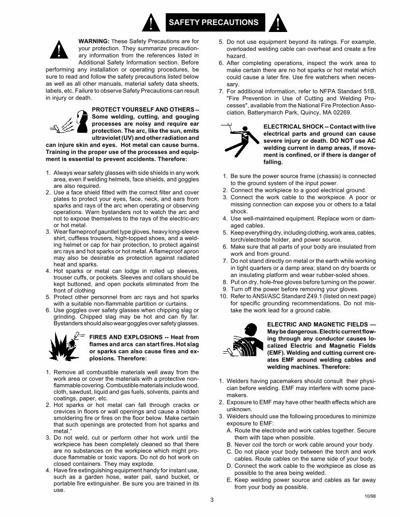
WARNING: These Safety Precautions are foryour protection. They summarize precaution-ary information from the references listed inAdditional Safety Information section. Before
performing any installation or operating procedures, besure to read and follow the safety precautions listed belowas well as all other manuals, material safety data sheets,labels, etc. Failure to observe Safety Precautions can resultin injury or death.
PROTECT YOURSELF AND OTHERS --Some welding, cutting, and gougingprocesses are noisy and require earprotection. The arc, like the sun, emitsultraviolet (UV) and other radiation and
can injure skin and eyes. Hot metal can cause burns.Training in the proper use of the processes and equip-ment is essential to prevent accidents. Therefore:
1. Always wear safety glasses with side shields in any workarea, even if welding helmets, face shields, and gogglesare also required.
2. Use a face shield fitted with the correct filter and coverplates to protect your eyes, face, neck, and ears fromsparks and rays of the arc when operating or observingoperations. Warn bystanders not to watch the arc andnot to expose themselves to the rays of the electric-arcor hot metal.
3. Wear flameproof gauntlet type gloves, heavy long-sleeveshirt, cuffless trousers, high-topped shoes, and a weld-ing helmet or cap for hair protection, to protect againstarc rays and hot sparks or hot metal. A flameproof apronmay also be desirable as protection against radiatedheat and sparks.
4. Hot sparks or metal can lodge in rolled up sleeves,trouser cuffs, or pockets. Sleeves and collars should bekept buttoned, and open pockets eliminated from thefront of clothing
5. Protect other personnel from arc rays and hot sparkswith a suitable non-flammable partition or curtains.
6. Use goggles over safety glasses when chipping slag orgrinding. Chipped slag may be hot and can fly far.Bystanders should also wear goggles over safety glasses.
FIRES AND EXPLOSIONS -- Heat fromflames and arcs can start fires. Hot slagor sparks can also cause fires and ex-plosions. Therefore:
1. Remove all combustible materials well away from thework area or cover the materials with a protective non-flammable covering. Combustible materials include wood,cloth, sawdust, liquid and gas fuels, solvents, paints andcoatings, paper, etc.
2. Hot sparks or hot metal can fall through cracks orcrevices in floors or wall openings and cause a hiddensmoldering fire or fires on the floor below. Make certainthat such openings are protected from hot sparks andmetal.“
3. Do not weld, cut or perform other hot work until theworkpiece has been completely cleaned so that thereare no substances on the workpiece which might pro-duce flammable or toxic vapors. Do not do hot work onclosed containers. They may explode.
4. Have fire extinguishing equipment handy for instant use,such as a garden hose, water pail, sand bucket, orportable fire extinguisher. Be sure you are trained in itsuse.
SAFETY PRECAUTIONS
10/98
5. Do not use equipment beyond its ratings. For example,overloaded welding cable can overheat and create a firehazard.
6. After completing operations, inspect the work area tomake certain there are no hot sparks or hot metal whichcould cause a later fire. Use fire watchers when neces-sary.
7. For additional information, refer to NFPA Standard 51B,"Fire Prevention in Use of Cutting and Welding Pro-cesses", available from the National Fire Protection Asso-ciation, Batterymarch Park, Quincy, MA 02269.
ELECTRICAL SHOCK -- Contact with liveelectrical parts and ground can causesevere injury or death. DO NOT use ACwelding current in damp areas, if move-ment is confined, or if there is danger offalling.
1. Be sure the power source frame (chassis) is connectedto the ground system of the input power.
2. Connect the workpiece to a good electrical ground.3. Connect the work cable to the workpiece. A poor or
missing connection can expose you or others to a fatalshock.
4. Use well-maintained equipment. Replace worn or dam-aged cables.
5. Keep everything dry, including clothing, work area, cables,torch/electrode holder, and power source.
6. Make sure that all parts of your body are insulated fromwork and from ground.
7. Do not stand directly on metal or the earth while workingin tight quarters or a damp area; stand on dry boards oran insulating platform and wear rubber-soled shoes.
8. Put on dry, hole-free gloves before turning on the power.9. Turn off the power before removing your gloves.
10. Refer to ANSI/ASC Standard Z49.1 (listed on next page)for specific grounding recommendations. Do not mis-take the work lead for a ground cable.
ELECTRIC AND MAGNETIC FIELDS —May be dangerous. Electric current flow-ing through any conductor causes lo-calized Electric and Magnetic Fields(EMF). Welding and cutting current cre-ates EMF around welding cables andwelding machines. Therefore:
1. Welders having pacemakers should consult their physi-cian before welding. EMF may interfere with some pace-makers.
2. Exposure to EMF may have other health effects which areunknown.
3. Welders should use the following procedures to minimizeexposure to EMF:A. Route the electrode and work cables together. Secure
them with tape when possible.B. Never coil the torch or work cable around your body.C. Do not place your body between the torch and work
cables. Route cables on the same side of your body.D. Connect the work cable to the workpiece as close as
possible to the area being welded.E. Keep welding power source and cables as far away
from your body as possible.
4
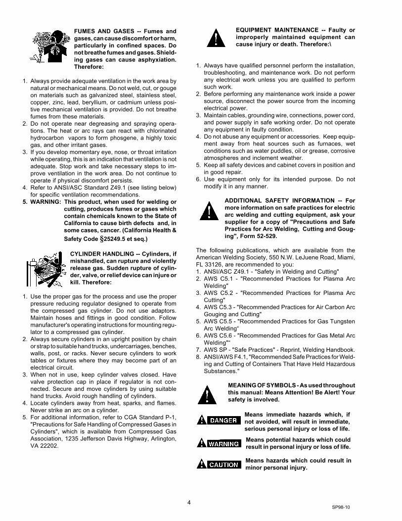
FUMES AND GASES -- Fumes andgases, can cause discomfort or harm,particularly in confined spaces. Donot breathe fumes and gases. Shield-ing gases can cause asphyxiation.Therefore:
1. Always provide adequate ventilation in the work area bynatural or mechanical means. Do not weld, cut, or gougeon materials such as galvanized steel, stainless steel,copper, zinc, lead, beryllium, or cadmium unless posi-tive mechanical ventilation is provided. Do not breathefumes from these materials.
2. Do not operate near degreasing and spraying opera-tions. The heat or arc rays can react with chlorinatedhydrocarbon vapors to form phosgene, a highly toxicgas, and other irritant gases.
3. If you develop momentary eye, nose, or throat irritationwhile operating, this is an indication that ventilation is notadequate. Stop work and take necessary steps to im-prove ventilation in the work area. Do not continue tooperate if physical discomfort persists.
4. Refer to ANSI/ASC Standard Z49.1 (see listing below)for specific ventilation recommendations.
5. WARNING: This product, when used for welding orcutting, produces fumes or gases whichcontain chemicals known to the State ofCalifornia to cause birth defects and, insome cases, cancer. (California Health &Safety Code §25249.5 et seq.)
CYLINDER HANDLING -- Cylinders, ifmishandled, can rupture and violentlyrelease gas. Sudden rupture of cylin-der, valve, or relief device can injure orkill. Therefore:
1. Use the proper gas for the process and use the properpressure reducing regulator designed to operate fromthe compressed gas cylinder. Do not use adaptors.Maintain hoses and fittings in good condition. Followmanufacturer's operating instructions for mounting regu-lator to a compressed gas cylinder.
2. Always secure cylinders in an upright position by chainor strap to suitable hand trucks, undercarriages, benches,walls, post, or racks. Never secure cylinders to worktables or fixtures where they may become part of anelectrical circuit.
3. When not in use, keep cylinder valves closed. Havevalve protection cap in place if regulator is not con-nected. Secure and move cylinders by using suitablehand trucks. Avoid rough handling of cylinders.
4. Locate cylinders away from heat, sparks, and flames.Never strike an arc on a cylinder.
5. For additional information, refer to CGA Standard P-1,"Precautions for Safe Handling of Compressed Gases inCylinders", which is available from Compressed GasAssociation, 1235 Jefferson Davis Highway, Arlington,VA 22202.
EQUIPMENT MAINTENANCE -- Faulty orimproperly maintained equipment cancause injury or death. Therefore:\
1. Always have qualified personnel perform the installation,troubleshooting, and maintenance work. Do not performany electrical work unless you are qualified to performsuch work.
2. Before performing any maintenance work inside a powersource, disconnect the power source from the incomingelectrical power.
3. Maintain cables, grounding wire, connections, power cord,and power supply in safe working order. Do not operateany equipment in faulty condition.
4. Do not abuse any equipment or accessories. Keep equip-ment away from heat sources such as furnaces, wetconditions such as water puddles, oil or grease, corrosiveatmospheres and inclement weather.
5. Keep all safety devices and cabinet covers in position andin good repair.
6. Use equipment only for its intended purpose. Do notmodify it in any manner.
ADDITIONAL SAFETY INFORMATION -- Formore information on safe practices for electricarc welding and cutting equipment, ask yoursupplier for a copy of "Precautions and SafePractices for Arc Welding, Cutting and Goug-ing", Form 52-529.
The following publications, which are available from theAmerican Welding Society, 550 N.W. LeJuene Road, Miami,FL 33126, are recommended to you:1. ANSI/ASC Z49.1 - "Safety in Welding and Cutting"2. AWS C5.1 - "Recommended Practices for Plasma Arc
Welding"3. AWS C5.2 - "Recommended Practices for Plasma Arc
Cutting"4. AWS C5.3 - "Recommended Practices for Air Carbon Arc
Gouging and Cutting"5. AWS C5.5 - "Recommended Practices for Gas Tungsten
Arc Welding“6. AWS C5.6 - "Recommended Practices for Gas Metal Arc
Welding"“7. AWS SP - "Safe Practices" - Reprint, Welding Handbook.8. ANSI/AWS F4.1, "Recommended Safe Practices for Weld-
ing and Cutting of Containers That Have Held HazardousSubstances."
MEANING OF SYMBOLS - As used throughoutthis manual: Means Attention! Be Alert! Yoursafety is involved.
Means immediate hazards which, ifnot avoided, will result in immediate,serious personal injury or loss of life.
Means potential hazards which couldresult in personal injury or loss of life.
Means hazards which could result inminor personal injury.
SP98-10

5
a. Éloigner suffisamment tous les matériaux combus-tibles du secteur où l’on exécute des soudures ou descoupes à l’arc, à moins de les recouvrir complètementd’une bâche non-inflammable. Ce type de matériauxcomprend notamment le bois, les vêtements, la sciure,l’essence, le kérosène, les peintures, les solvants, legaz naturel, l’acétylène, le propane et autres sub-stances combustibles semblables.
b. Les étincelles ou les projections de métal incandes-cent peuvent tomber dans des fissures du plancher oudans des ouvertures des murs et y déclencher uneignition lente cachée. Veiller à protéger ces ouverturesdes étincelles et des projections de métal.
c. N’exécutez pas de soudures, de coupes, d’opérationsde gougeage ou autres travaux à chaud à la surfacede barils, bidons, réservoirs ou autres contenantsusagés, avant de les avoir nettoyés de toute trace desubstance susceptible de produire des vapeursinflammables ou toxiques.
d. En vue d’assurer la prévention des incendies, ilconvient de disposer d’un matériel d’extinction prêt àservir immédiatement, tel qu’un tuyau d’arrosage, unseau à eau, un seau de sable ou un extincteur portatif.
e. Une fois le travail à l’arc terminé, inspectez le secteurde façon à vous assurer qu’aucune étincelle ou projec-tion de métal incandescent ne risque de provoquerultérieurement un feu.
3. CHOC ÉLECTRIQUE-- Le gougeage à l’arc et à l’arcau plasma exige l’emploi de tensions à viderelativement importantes; or, celles-ci risquent decauser des dommages corporels graves et mêmemortels en cas d’utilisation inadéquate. La gravité duchoc électrique reçu dépend du chemin suivi par lecourant à travers le corps humain et de son intensité.
a. Ne laissez jamais de surfaces métalliques sous ten-sion venir au contact direct de la peau ou devêtements humides. Veillez à porter des gants biensecs.
b. Si vous devez effectuer un travail sur une surfacemétallique ou dans un secteur humide, veillez à assu-rer votre isolation corporelle en portant des gants secset des chaussures à semelles de caoutchouc et envous tenant sur une planche ou une plate-formesèche.
c. Mettez toujours à la terre le poste de soudage/coupageen le reliant par un câble à une bonne prise de terre.
d. N’utilisez jamais de câbles usés ou endommagés. Nesurchargez jamais le câble. Utilisez toujours unéquipement correctement entretenu.
e. Mettez l’équipement hors tension lorsqu’il n’est pas enservice. une mise à la masse accidentelle peut en effetprovoquer une surchauffe de l’équipement et un dan-ger d’incendie. Ne pas enrouler ou passer le câbleautour d’une partie quelconque du corps.
f. Vérifiez si le câble de masse est bien relié à la pièce enun point aussi proche que possible de la zone detravail. Le branchement des câbles de masse àl’ossature du bâtiment ou en un point éloigné de lazone de travail augmente en effet le risque de pas-sage d’un courant de sortie par des chaînes delevage
PRÉCAUTIONS DE SÉCURITÉAVERTISSEMENT: Ces règles de sécurité ont pour objetd’ assurer votre protection. Veillez à lire et à observer lesprécautions énoncées ci-dessous avant de monter l’équipement ou de commercer à l’utiliser. Tout défautd’observation de ces précautions risque d’entraîner desblessures graves ou mortelles.1. PROTECTION INDIVIDUELLE-- Les brûlures de la
peau et des yeux dues au rayonnement de l’arcélectrique ou du métal incandescent, lors du soudageau plasma ou à l’électrode ou lors du gougeage àl’arc, peuvent s’avérer plus graves que cellesrésultant d’une exposition prolongée au soleil. Aussiconvient-il d’observer les précautions suivantes:
a. Portez un écran facial adéquat muni des plaquesprotectrices et des verres filtrants appropriés afin devous protéger les yeux, le visage, le cou et les oreillesdes étincelles et du rayonnement de l’arc électriquelorsque vous effectuez des soudures ou des coupesou lorsque vous en observez l’exécution.
AVERTISSEZ les personnes se trouvant à proximitéde façon à ce qu’elles ne regardent pas l’arc et à cequ’elles ne s’exposent pas à son rayonnement, ni àcelui du métal incandescent.
b. Portez des gants ignifugés à crispins, une tuniqueépaisse à manches longues, des pantalons sansrebord, des chaussures à embout d’acier et uncasque de soudage ou une calotte de protection, afind’éviter d’exposer la peau au rayonnement de l’arcélectrique ou du métal incandescent. ll est égalementsouhaitable d’utiliser un tablier ininflammable defaçon à se protéger des étincelles et du rayonnementthermique.
c. Les étincelles ou les projections de métal incandes-cent risquent de se loger dans des manchesretroussées, des bords relevés de pantalons ou dansdes poches. Aussi convient-il de garder boutonnés lecol et les manches et de porter des vêtements sanspoches à l’avant.
d. Protégez des étincelles et du rayonnement de l’arcélectrique les autres personnes travaillant à proximitéà l’aide d’un écran ininflammable adéquat.
e. Ne jamais omettre de porter des lunettes de sécuritélorsque vous vous trouvez dans un secteur où l’oneffectue des opérations de soudage ou de coupage àl’arc. Utilisez des lunettes de sécurité à écrans ouverres latéraux pour piquer ou meûler le laitier. Lespiquetures incandescentes de laitier peuvent êtreprojetées à des distances considérables. Lespersonnes se trouvant à proximité doivent égalementporter des lunettes de protection.
f. Le gougeage à l’arc et le soudage à l’arc au plasmaproduisent un niveau de bruit extrêmement élevé (de100 à 114 dB) et exigent par conséquent l’emploi dedispositifs appropriés de protection auditive.
2. PRÉVENTION DES INCENDES-- Les projections delaitier incandescent ou d’étincelles peuventprovoquer de graves incendies au contact dematériaux combustibles solides, liquides ou gazeux.Aussi faut-il observer les précautions suivantes:
9/97
6
des câbles de grue ou divers chemins électriques.g. Empêchez l’apparition de toute humidité, notamment
sur vos vêtements, à la surface de l’emplacement detravail, des câbles, du porte-électrode et du poste desoudage/coupage. Réparez immédiatement toutefuite d’eau.
4. VENTILATION-- La respiration prolongée des fuméesrésultant des opérations de soudage/coupage, àl’intérieur, d’un local clos, peut provoquer des mal-aises et des dommages corporels. Aussi convient-ild’observer les précautions suivantes:
a. Assurez en permanence une aération adéquate del’emplacement de travail en maintenant une ventila-tion naturelle ou à l’aide de moyens mécaniques.N’effectuez jamais de travaux de soudage ou decoupage sur des matériaux de zinc, de plomb, deberyllium ou de cadmium en l’absence de moyensmécaniques de ventilation capables d’empêcherl’inhalation des fumées dégagées par ces matériaux.
b. N’effectuez jamais de travaux de soudage ou decoupage à proximité de vapeurs d’hydrocarburechloré résultant d’opérations voisines de dégraissageou de pulvérisation. La chaleur dégagée ou lerayonnement de l’arc peut déclencher la formation dephosgène -- gaz particulièrement toxique -- et d’autresgaz irritants, à partir des vapeurs de solvant.
c. Une irritation momentanée des yeux, du nez ou de lagorge constatée au cours de l’utilisation del’équipement dénote un défaut de ventilation. Arrêtez-vous de travailler afin de prendre les mesures néces-saires à l’amélioration de la ventilation. Ne poursuivezpas l’opération entreprise si le malaise persiste.
d. Certaines commandes comportent des canalisationsoù circule de l’hydrogène. L’armoire de commande estmunie d’un ventilateur destiné à empêcher la forma-tion de poches d’hydrogène, lesquelles présentent undanger d’explosion; ce ventilateur ne fonctionne quesi l’interrupteur correspondant du panneau avant setrouve placé en position ON (Marche). Veillez àmanœuvrer cette commande en vérifiant si lecouvercle est bien en place, de façon à assurerl’efficacité de la ventilation ainsi réalisée. Ne jamaisdébrancher le ventilateur.
e. Les fumées produites par l’opération de soudage oude coupage peuvent s’avérer toxiques. Aussi est-ilnécessaire de disposer en permanence d’un dispositifadéquat de ventilation de type aspirant, afin d’élimi-ner du voisinage de l’opérateur tout dégagement defumée visible.
f. Consultez les recommandations particulières enmatière de ventilation indiquées à l’alinéa 6 de lanorme Z49.1 de l’AWS.
5. ENTRETIEN DE L’ÉQUIPEMENT-- Un équipemententretenu de façon défectueuse ou inadéquate risquenon seulement de réaliser un travail de mauvaisequalité mais, chose plus grave encore, d’entraîner des
dommages corporels graves, voire mortels endéclenchant des incendies ou des chocs électriques.Observez par conséquent les précautions suivantes:
a. Efforcez-vous de toujours confier à un personnel qua-lifié l’installation, le dépannage et l’entretien du postede soudage et de coupage. N’effectuez aucuneréparation électrique sur l’équipement à moins d’êtrequa-lifié à cet effet.
b. Ne procédez jamais à une tâche d’entretienquelconque à l’intérieur du poste de soudage/coupage, avant d’avoir débranché l’alimentationélectrique.
c. Maintenez en bon état de fonctionnement les câbles,le câble de masse, les branchements, le cordond’alimentation et le poste de soudage/coupage.N’utilisez jamais le poste ou l’équipement s’il présenteune défectuosité quelconque.
d. Prenez soin du poste de soudage et de coupage et deséquipements accessoires. Gardez-les à l’écart dessources de charleur, notamment des fours, del’humidité, des flaques d’eau maintenez-les à l’abri destraces d’huile ou de graisse, des atmosphères corro-sives et des intempéries.
e. Laissez en place tous les dispositifs de sécurité et tousles panneaux de l’armoire de commande en veillant àles garder en bon état.
f. Utilisez le poste de soudage/coupage conformément àson usage prévu et n’effectuez aucune modification.
6. INFORMATIONS COMPLÉMENTAIRES RELATIVESÀ LA SÉCURITÉ--
Pour obtenir des informations complémentaires sur lesrègles de sécurité à observer pour le montage etl’utilisation d’équipements de soudage et de coupageélectriques et sur les méthodes de travailrecommandées, demandez un exemplaire du livret N°52529 “Precautions and Safe Practices for Arc Weld-ing, Cutting and Gouging” publié par ESAB. Nousconseillons également de consulter les publicationssui-vantes, tenues à votre disposition par l’AmericanWelding Society, 550 N.W. LeJuene Road, Miami, FL32126:
a. “Safety in Welding and Cutting” AWS Z49.1b. “Recommended Safe Practices for Gas-Shielded Arc
Welding “AWS A6. 1.c. “Safe Practices for Welding and Cutting Containers
That Have Held Combustibles” AWS-A6.0.d. “Recommended Safe Practices for Plasma Arc Cutting”
AWS-A6. 3.e. “Recommended Safe Practices for Plasma Arc Weld-
ing” AWS-C5. 1.f. “Recommended Safe Practices for Air Carbon Arc
Gouging and Cutting” AWS-C5. 3.g. “Code For Safety in Welding and Cutting”
CSA-Standard W117. 2.
9/97

SECTION 1 DESCRIPTION
7
1.1 GENERAL
The PCM-1125 is a compact, completely self-containedplasma cutting system. As shipped, the system is fullyassembled and ready to cut after being connected toinput power and a source of compressed air (90-150 psi).The PCM-1125 package uses the heavy-duty PT-27 torchto deliver cutting power for severing materials up to 1-1/4inch thick. Refer to the following paragraphs for descrip-tions of the PCM-1125 packages available as well asperformance specifications.
Use only ESAB Plasmarc torches that are designedfor use with this console. Use of torches not de-signed for use with this console could create anELECTRIC SHOCK HAZARD. Do NOT use or modifythe PT-23, PCT-80 or any other torch for use on thisconsole.
1.2 SCOPE
The purpose of this manual is to provide the operator withall the information required to install and operate the
PCM-1125 plasma arc cutting package. Technical refer-ence material is also provided to assist in troubleshoot-ing the cutting package.
1.3 PACKAGES AVAILABLE
PCM-1125 listed on the front cover includes the followingcomponents:
PT-27 Torch, 75° head, 25-ft. ..................P/N 21661PT-27 Spare Parts Kit (see Table 1-1) ....P/N 21623PCM-1125 Console/Power Source .......... See below
Depending on the choice of input power, each packageincludes the following appropriate PCM-1125 Console/Power Source:
208/230 V, 50/60 Hz, 1 or 3-phase ..........P/N 37495460 V, 50/60 Hz, 3-phase ........................P/N 37497575 V, 60 Hz, 3-phase .............................P/N 37499
Table 1-1. PT-27 Spare Parts Kit, P/N 21623, Contents
Description Part Number Quantity
50 - 70 A NozzleElectrodeSwirl BaffleHeat ShieldStandoff GuideValve Pin
333693336633367216162142021619
431211
SECTION 1 DESCRIPTION
8
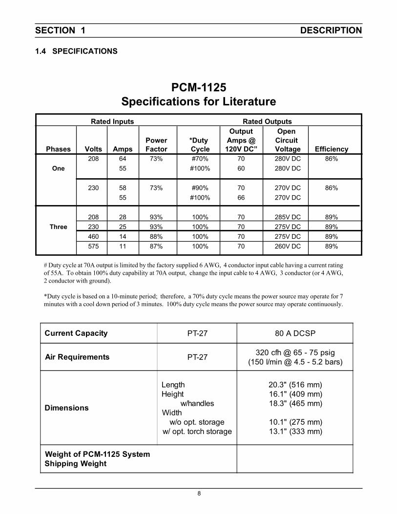
1.4 SPECIFICATIONS
Current Capacity PT-27 80 A DCSP
Air Requirements PT-27 320 cfh @ 65 - 75 psig(150 l/min @ 4.5 - 5.2 bars)
Dimensions
LengthHeight
w/handlesWidth
w/o opt. storagew/ opt. torch storage
20.3" (516 mm)16.1" (409 mm)18.3" (465 mm)
10.1" (275 mm)13.1" (333 mm)
Weight of PCM-1125 SystemShipping Weight
# Duty cycle at 70A output is limited by the factory supplied 6 AWG, 4 conductor input cable having a current ratingof 55A. To obtain 100% duty capability at 70A output, change the input cable to 4 AWG, 3 conductor (or 4 AWG,2 conductor with ground).
*Duty cycle is based on a 10-minute period; therefore, a 70% duty cycle means the power source may operate for 7minutes with a cool down period of 3 minutes. 100% duty cycle means the power source may operate continuously.
PCM-1125Specifications for Literature
Rated Inputs Rated OutputsOutput Open
Power *Duty Amps @ CircuitPhases Volts Amps Factor Cycle 120V DC” Voltage Efficiency
208 64 73% #70% 70 280V DC 86%One 55 #100% 60 280V DC
230 58 73% #90% 70 270V DC 86%55 #100% 66 270V DC
208 28 93% 100% 70 285V DC 89%Three 230 25 93% 100% 70 275V DC 89%
460 14 88% 100% 70 275V DC 89%575 11 87% 100% 70 260V DC 89%

SECTION 1 DESCRIPTION
9
Table 1-3. PT-27 Torch Specifications
Current Capacity (100% duty)Length of Service LinesWeight 25 ft 50 ft
80 A DCSP25 ft or 50 ft
5.2 lbs (2.4 kg)9.6 lbs (4.4 kg)
7.3" (185 mm)
1" (25.4 mm)
1"(25.4 mm)
75°
3" (76 mm)
Figure 1-1. PT-27 Dimensions
1.5 OPTIONAL ACCESSORIES
1. Torch Wrap/Spare Parts Kit Holder, P/N 33952GY.Units have 4 mounting holes on left side for mountingthis accessory holder.
2. Wheel Cart, P/N 34324. This 5 7/8" high cart hasfront swivel casters and rear casters to make iteasier to roll the PCM-1125 around the job site.
Figure 1-2. PT-27/PCM-1125 Cutting Performance
PT-27, PCM-1125, 70A, air, Carbon Steel
0102030405060708090
0 0.5 1 1.5
Plate Thickness (in)
Cut
ting
Spee
d (in
/min
)
60 ANozzle
90 in/min max speed of side beam
SECTION 2 INSTALLATION
10
2.1 GENERAL
Proper installation is important for satisfactory and trouble-free operation of the PCM-1125 cutting package. It issuggested that each step in this section be studiedcarefully and followed closely.
2.2 EQUIPMENT REQUIRED
A source of clean, dry air that supplies 320 cfh at 65-75psig is required for the cutting operation. The air supplyshould not exceed 150 psig (the maximum inlet pressurerating of the air filter-regulator supplied with the pack-age).
2.3 LOCATION
Adequate ventilation is necessary to provide propercooling of the PCM-1125. The amount of dirt, dust, andexcessive heat to which the equipment is exposed,should be minimized. There should be at least one footof clearance between the PCM-1125 power source andwall or any other obstruction to allow freedom of airmovement through the power source.
Installing or placing any type of filtering device willrestrict the volume of intake air, thereby subjectingthe power source internal components to overheat-ing. The warranty is void if any type of filter deviceis used.
2.4 INSPECTION
A. Remove the shipping container and all packingmaterial and inspect for evidence of concealeddamage which may not have been apparent uponreceipt of the PCM-1125. Notify the carrier of anydefects or damage at once.
B. Check container for any loose parts prior to dispos-ing of shipping materials.
C. Check air louvers and any other openings to ensurethat any obstruction is removed.
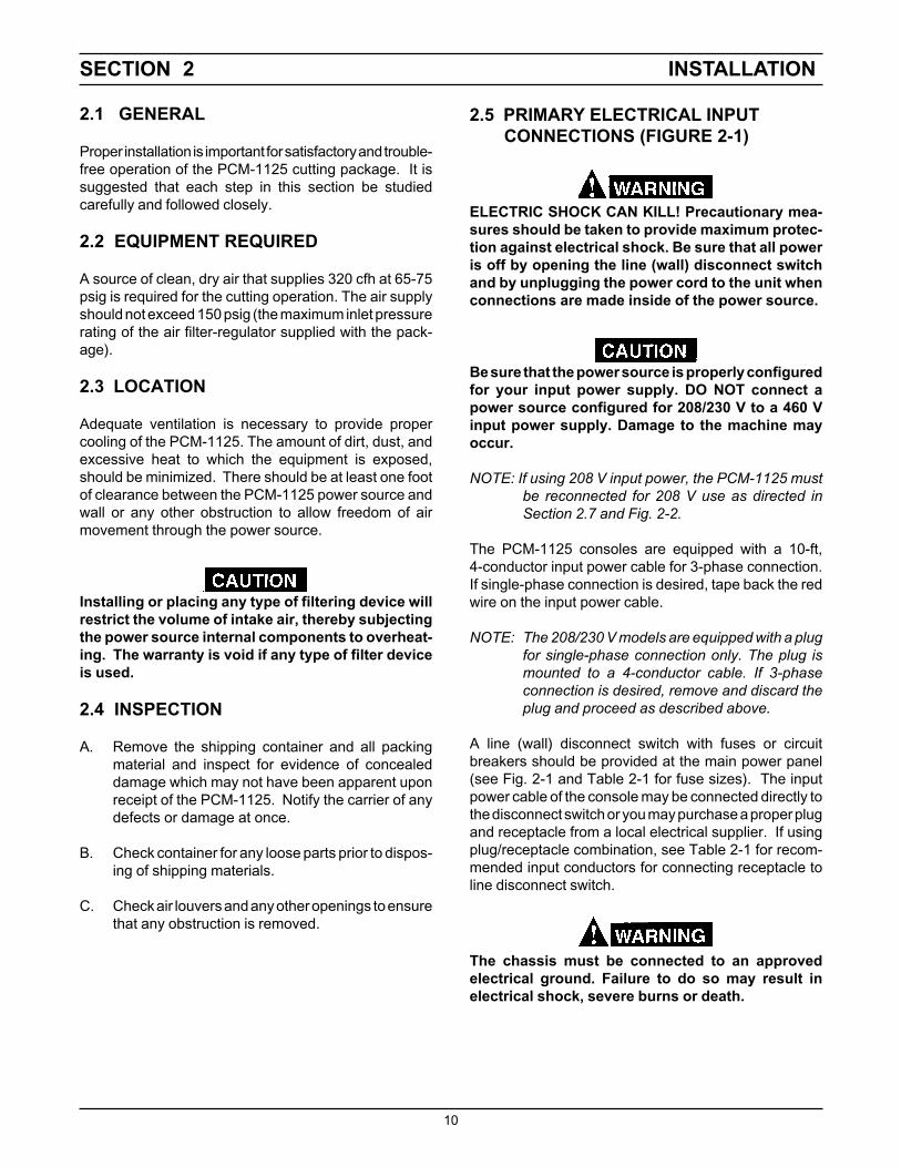
2.5 PRIMARY ELECTRICAL INPUT CONNECTIONS (FIGURE 2-1)
ELECTRIC SHOCK CAN KILL! Precautionary mea-sures should be taken to provide maximum protec-tion against electrical shock. Be sure that all poweris off by opening the line (wall) disconnect switchand by unplugging the power cord to the unit whenconnections are made inside of the power source.
Be sure that the power source is properly configuredfor your input power supply. DO NOT connect apower source configured for 208/230 V to a 460 Vinput power supply. Damage to the machine mayoccur.
NOTE: If using 208 V input power, the PCM-1125 mustbe reconnected for 208 V use as directed inSection 2.7 and Fig. 2-2.
The PCM-1125 consoles are equipped with a 10-ft,4-conductor input power cable for 3-phase connection.If single-phase connection is desired, tape back the redwire on the input power cable.
NOTE: The 208/230 V models are equipped with a plugfor single-phase connection only. The plug ismounted to a 4-conductor cable. If 3-phaseconnection is desired, remove and discard theplug and proceed as described above.
A line (wall) disconnect switch with fuses or circuitbreakers should be provided at the main power panel(see Fig. 2-1 and Table 2-1 for fuse sizes). The inputpower cable of the console may be connected directly tothe disconnect switch or you may purchase a proper plugand receptacle from a local electrical supplier. If usingplug/receptacle combination, see Table 2-1 for recom-mended input conductors for connecting receptacle toline disconnect switch.
The chassis must be connected to an approvedelectrical ground. Failure to do so may result inelectrical shock, severe burns or death.

SECTION 2 INSTALLATION
11
1. For operator safety, the torch connections are lo-cated on the output terminal board behind the lowerportion of the front panel. Remove access door tooutput terminal board from right panel of powersource.
2. Thread the power cable, pilot arc cable and switchlead of the PT-27 through the right open bushing ofthe front panel. Connect power cable to the torchfitting (left-hand threads); bolt the pilot arc cable ringconnection to the copper terminal; and plug in theswitch lead to the torch switch receptable on theoutput terminal board. Make sure the power and pilotarc cable connections are wrench-tight. Make sureplug of switch lead is firmly locked in place.
3. Reassemble the access door to the power source.4. Connect your air supply to the inlet connection of the
filter-regulator.5. Clamp the work cable to the workpiece. Be sure the
workpiece is connected to an approved earth groundwith a properly sized ground cable.
Table 2-1. Recommended Sizes ForInput Conductors and Line Fuses
Input Requirements Input & Gnd FuseVolts Phase Amps Conductor Size
CU/AWG Amps208 1 64 4 90208 3 28 10 50230 1 58 4 90230 3 25 10 40460 3 14 10 25575 3 11 10 20
2.6SECONDARY (OUTPUT) CONNECTIONS(REFER TO FIG. 2-1)
Before making any connections to the power sourceoutput terminals, make sure that all primary inputpower to the power source is deenergized (off) at themain disconnect switch and that the input powercable is unplugged.

SECTION 2 INSTALLATION
12
WORK
SAFETYGROUND
PT-27
Allow at least 10 ft. (3m)between work and power source
TORCHSWITCHRECEPTACLE
ACCESS DOOR FORTORCH CONNECTION
Prefiltered AIR SUPPLY(Customer Supplied)(90 to 150 psig max)
CUSTOMER FUSED LINEDISCONNECT SWITCH(SeeTable 2.1 and WARNING inregards to chassis ground inSection 2.5.)
TORCHPOWERCABLECONNECTION
TORCHPILOTARCCONNECTION
INPUT POWER CABLE(See Table 2.1)
Figure 2-1. PCM-1125 Interconnection Diagram
NOTE: The 208/230 V model is equipped with a plug for single-phase connection only. The plug is mounted to a 4-conductor cable. If 3-phase connection is desired, removeand discard the plug and refer to Sect. 2.5.
ACCESS FOR CNCINTERFACE CONNEC-TIONS.(See Detail “A”)
CNC INTERFACE CONNECTION(INSIDE ON LEFT SIDE OF BASE.)
DETAIL “A”

SECTION 2 INSTALLATION
13
1. Remove cover from the PCM-1125 power source.2. Locate the Input Bridge (IBR) and TB5 terminal
block (see Fig. 1) on the left side towards the rearpanel. Disconnect the gray lead from TB5-2 andthen connect it to TB5-1.
3. Locate the output bridge (D2) on left side towards thefront panel (see Fig. 2). Disconnect and interchangeleads X2 and X3 from the main transformer. For 208vac input, X2 is connected to TB3 and X3 is con-nected to terminal 3 of D2. Make sure the connec-tions are firmly tightened.
4. Leave all other wires the same.5. Reinstall cover and connect the PCM-1125 to 208
vac input power.
Fig. 2
Connecting PCM-1125 for 208 Vac Input
ELECTRIC SHOCK CAN KILL! Precautionary mea-sures should be taken to provide maximum protec-tion against electrical shock. Be sure that all poweris off by opening the line (wall) disconnect switchand by unplugging the power cord to the unit whenreconnecting for 208 VAC Input.
The PCM-1125 power source with 208/230 vac, 1-phaseinput capability is factory set for 230 vac input. If using208 vac input, the PCM-1125 must be reconnected asfollows before connecting to your input power:
RR2
S G
T +
(IBR)INPUTBRIDGE
Fig. 1
Figure 2-2. Original Factory Setup for 230 Vac Input onPower Source with 208/230 Vac Input Power Capability
Note: Factory set for 230 VAC input.For 208VAC move Gry wire from TB5-2 toTB5-1, move T1-X2 to TB3 and T1-X3 to D2-3
SECTION 2 INSTALLATION
14
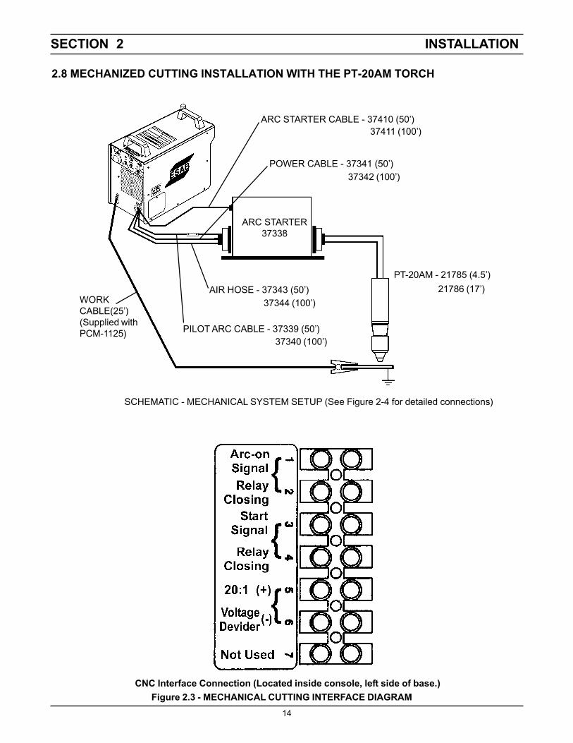
PILOT ARC CABLE - 37339 (50’)37340 (100’)
POWER CABLE - 37341 (50’)37342 (100’)
ARC STARTER37338
WORKCABLE(25’)(Supplied withPCM-1125)
AIR HOSE - 37343 (50’)37344 (100’)
ARC STARTER CABLE - 37410 (50’)37411 (100’)
PT-20AM - 21785 (4.5’)21786 (17’)
SCHEMATIC - MECHANICAL SYSTEM SETUP (See Figure 2-4 for detailed connections)
Figure 2.3 - MECHANICAL CUTTING INTERFACE DIAGRAMCNC Interface Connection (Located inside console, left side of base.)
2.8 MECHANIZED CUTTING INSTALLATION WITH THE PT-20AM TORCH

SECTION 2 INSTALLATION
15
Figure 2.4 Connection Diagram - PCM-1125/PT-20AM with Arc Starter
View A-A
“A”
“B”“C”“D”
PILOT ARC CABLE - 37339 (50’)37340 (100’)
POWER CABLE - 37341 (50’)37342 (100’)
AIR HOSE - 37343 (50’)
ARC STARTER CABLE - 37410 (50’)37411 (100’)
SPLICE CONNECTOR*(Supplied with 37338)
25mm min.
37344 (100’)
Arc Starter37338
SPLICE CONNECTOR*(Supplied with 37338)
25mm min.
PT-20AMTORCH
*Insulate splice connec-tors with vinyl tubingand secure with electricaltape. SPARK GAP ASSEMBLY
(Torch end of Arc Starter)
.035” (0.9mm)
MOUNTING DIMENSIONS
7”(178mm)
(4) .250” (6 mm)
Disconnect TheseTwo Black Leads
Connect Arc Start Cable As Shown. (See step 5 below).
BLK Arc Start
WHT Arc Start
Arc StarterCable (Ref.)
ADAPTOR - 999278
2.125”(54mm)
Make sure all power is off before making followingconnections.
1. Remove cover from PCM-1125.2. Insert the 4 service lines from Arc Starter through
the torch opening of front panel.3. Connect large hole terminal end of Pilot Arc Cable
("A") to connection where shown. Tighten screwfirmly.
4. Connect adaptor 999278 to fitting where shown.Connect Air Hose ("C") to adaptor. Connect powercable ("B") to one of the threaded holes of adaptor.Tighten all connections firmly.
5. Locate TB1 Terminal Block. Referring to view D-Dabove, disconnect the two black wires from TB1.Connect the black lead of Arc Starter Cable ("D") toTB1-1 and the white lead to TB1-2.
6. Reassemble cover. Proceed to connect the 4 ser-vice lines to the Arc Starter. Then connect PT-20AMtorch to Arc Stater.

SECTION 3 OPERATION
16
3.1 OPERATION
ELECTRIC SHOCK can kill.• Do NOT operate the unit with the cover removed.• Do NOT apply power to the unit while holding or
carrying the unit.• Do NOT touch any torch parts forward of the torch
handle (nozzle, heat shield, electrode, etc.) withpower switch on.
ARC RAYS can burn eyes and skin;NOISE can damage hearing.
• Wear welding helmet with No. 6 or 7 lens shade.• Wear eye, ear, and body protection.
Position the PCM-1125 at least 10 feet (3 meters)from the cutting area. Sparks and hot slag from thecutting operation can damage the unit.
3.2 PCM-1125 CONTROLS (FIGURE 3-1)
A. Power Switch (located on rear panel). Whenplaced in ON position, the green pilot light will glowindicating control circuit is energized and the cool-ing fan will run.
B. Output Current Control. Adjustable from 10 to70 amperes.
C. Air Test Switch. When placed in Test position, airfilter-regulator can be adjusted to desired pres-sure (65-75 psig) before cutting operations. Allowair to flow for a few minutes. This should removeany condensation that may have accumulatedduring shutdown period. Be sure to place switchin OPERATE position before starting cutting op-erations.
D. Trigger Lock Switch. When placed in LOCKposition, this permits releasing torch switch buttonafter cutting arc has been initiated. To extinguisharc at end of cut, press and release torch switchbutton again or pull torch away from work. Whenplaced in UNLOCK position, torch switch must beheld closed by the operator during the entirecutting operation and then released at the end ofcut.
E. Fault Light. Will glow amber under the followingconditions and operations will come to a completestop.
Flow Fault: The fault light will be mostly on butwill flick off for about 1/10th of a second everysecond. This indicates that the air flow supply islow.
Over Temperature: The fault light will be mostlyoff but will flick on for about 1/10th of a secondevery second. This indicates that the duty cyclehas been exceeded. Allow the power source tocool down before returning to operate.
High/Low Line Voltage: The fault light will rap-idly blink on and off (five times per second). Thisindicates that the input voltage is outside the “+ or-” 15% range of the input rating.
Over-Current: The fault light will be on continu-ously. This indicates that input current has beenexceeded.
All fault signals will remain on for a minimumof 10 seconds. If fault clears, all will resetautomatically except for over-current. To clearover-current, the power must be shut off for 5seconds and then turned back on.
3.3 CUTTING WITH THE PT-27
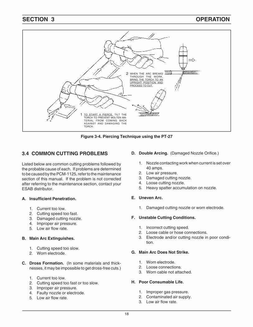
Use the following procedures to cut with the PT-27 torch(Figure 3-4).
A. Hold the torch nozzle approximately 1/8 to 3/16inch above the work and tilted at about 15 - 30°.This reduces the chance of spatter entering thenozzle. If the PT-27's standoff tool is being used,set the standoff between 3/16 and 1/4-inch.
B. Depress the torch switch. Air should flow from thetorch nozzle.
C. Two seconds after depressing the torch switch,the pilot arc should start. The main arc shouldimmediately follow, allowing the cut to begin. (Ifusing the trigger LOCK mode, torch switch may bereleased after establishing the cutting arc.)
D. After starting the cut, the torch should be main-tained at a 5-15° forward angle (Figure 3-2). Thisangle is especially useful in helping to create a"drop" cut. When not using the standoff guide, thenozzle should be held approximately 1/4 inch fromthe work.

SECTION 3 OPERATION
17
Figure 3-1. PCM-1125 Controls
E. When ending a cut, the torch switch should bereleased (press and release if using trigger LOCKmode) and lifted off the workpiece just before theend of the cut. This is to prevent the high frequencyfrom reigniting after cutting arc extinguishes andcausing damage to the nozzle (double arcing).
F. For rapid re-starts, such as grate or heavy meshcutting, do not release the torch switch. In thepostflow mode, the arc can be re-started immedi-ately by depressing the torch switch. This avoidsthe 2-second preflow portion of the cutting cycle.
REAR VIEW
AIR REGULATORCONTROL KNOB
FAULT LIGHT(AMBER)
POWER LIGHT(WHITE)
AIRPRESSURE
GAUGE
AIR TESTSWITCH
TRIGGER LOCKSWITCH
CURRENTCONTROL
KNOB
POWER ON-OFF(I-O) SWITCH &CIRCUIT BREAKER
FUSE (3A)
Figure 3-2. Recommended Torch Angle of 5° to 15°
NOTE: When replacing the nozzle, always inspect theelectrode for wear. If less than 19/32" of elec-trode shaft is remaining, replace the electrode.If the electrode is used beyond this recom-mended wear limit, damage to the torch andpower source may occur. Nozzle life is alsogreatly reduced when using the electrode belowthe recommended limit. Refer to Figure 3-3.
Figure 3-3. Electrode Wear Limit
19/32"
3.3.1. Drag Cutting with the PT-27/PCM-1125 System
Reduce current to 40 Amperes. Then follow steps inSection 3.3.
(15.1 mm)
ELECTRODE
REPLACE ELECTRODE BEFORELENGTH BECOMES SHORTERTHAN 19/32 INCH (15.1 MM)
SECTION 3 OPERATION
18
WHEN THE ARC BREAKSTHROUGH THE WORK,BRING THE TORCH TO ANUPRIGHT POSITION ANDPROCEED TO CUT.
TO START A PIERCE, TILT THETORCH TO PREVENT MOLTEN MA-TERIAL FROM COMING BACKAGAINST AND DAMAGING THETORCH.
1
2
Figure 3-4. Piercing Technique using the PT-27
3.4 COMMON CUTTING PROBLEMS
Listed below are common cutting problems followed bythe probable cause of each. If problems are determinedto be caused by the PCM-1125, refer to the maintenancesection of this manual. If the problem is not correctedafter referring to the maintenance section, contact yourESAB distributor.
A. Insufficient Penetration.
1. Current too low.2. Cutting speed too fast.3. Damaged cutting nozzle.4. Improper air pressure.5. Low air flow rate.
B. Main Arc Extinguishes.
1. Cutting speed too slow.2. Worn electrode.
C. Dross Formation. (In some materials and thick-nesses, it may be impossible to get dross-free cuts.)
1. Current too low.2. Cutting speed too fast or too slow.3. Improper air pressure.4. Faulty nozzle or electrode.5. Low air flow rate.
D. Double Arcing. (Damaged Nozzle Orifice.)
1. Nozzle contacting work when current is set over40 amps.
2. Low air pressure.3. Damaged cutting nozzle.4. Loose cutting nozzle.5. Heavy spatter accumulation on nozzle.
E. Uneven Arc.
1. Damaged cutting nozzle or worn electrode.
F. Unstable Cutting Conditions.
1. Incorrect cutting speed.2. Loose cable or hose connections.3. Electrode and/or cutting nozzle in poor condi-
tion.
G. Main Arc Does Not Strike.
1. Worn electrode.2. Loose connections.3. Worn cable not attached.
H. Poor Consumable Life.
1. Improper gas pressure.2. Contaminated air supply.3. Low air flow rate.

SECTION 4 MAINTENANCE
19
4.1 GENERAL
If this equipment does not operate properly, stop workimmediately and investigate the cause of the malfunc-tion. Maintenance work must be performed by anexperienced person, and electrical work by a trainedelectrician. Do not permit untrained persons to inspect,clean, or repair this equipment. Use only recommendedreplacement parts.
Be sure that the wall disconnect switch or wallcircuit breaker is open before attempting any in-spection or work inside of the PCM-1125.
4.2 INSPECTION AND CLEANING
Frequent inspection and cleaning of the PCM-1125 isrecommended for safety and proper operation. Somesuggestions for inspecting and cleaning are as follows:
A. Check work cable for secured connection toworkpiece.
B. Check safety earth ground at workpiece and atpower source chassis.
C. Check heat shield on torch. It should be replacedif damaged.
D. Check the torch electrode and cutting nozzle forwear on a daily basis. Remove spatter or replaceif necessary.
E. Make sure cable and hoses are not damaged orkinked.
F. Make sure all plugs, fittings, and ground connec-tions are tight.
G. With all input power disconnected, and wearingproper eye and face protection, blow out the insideof the PCM-1125 using low-pressure dry com-pressed air.
Water or oil occasionally accumulates in compressedair lines. Be sure to direct the first blast of air awayfrom the equipment to avoid damage to the PCM-1125.
H. Occasionally, bleed all water from the filter be-neath the air filter-regulator.
4.3 PT-27 TORCH CONSUMABLE PARTS
Make sure power switch on PCM-1125 is in OFFposition before working on the torch.
The PT-27 torch head contains a gas flow checkvalve that acts in conjunction with the flow switchand circuitry within the power source. This systemprevents the torch from being energized with highvoltage if the torch switch is accidentally closedwhen the shield is removed. Always replace torchwith the proper torch manufactured by ESAB sinceit alone contains ESAB¹s patented safety interlock.
To assemble the consumable parts, refer to Figure 4-1.
A. Place nozzle, swirl baffle and electrode into theshield as shown.
B. Thread assembly to the torch body and hand tighten.Always make sure the shield is very tight beforecutting.
Figure 4-1. Assembly of PT-27 Torch Front End Parts
SWIRL BAFFLE
ELECTRODE
NOZZLE
SHIELD
IMPORTANT!MAKE SHIELD VERY TIGHT!
SECTION 4 MAINTENANCE
20
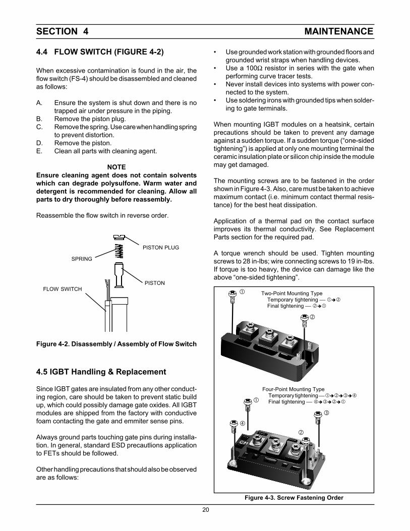
4.4 FLOW SWITCH (FIGURE 4-2)
When excessive contamination is found in the air, theflow switch (FS-4) should be disassembled and cleanedas follows:
A. Ensure the system is shut down and there is notrapped air under pressure in the piping.
B. Remove the piston plug.C. Remove the spring. Use care when handling spring
to prevent distortion.D. Remove the piston.E. Clean all parts with cleaning agent.
NOTEEnsure cleaning agent does not contain solventswhich can degrade polysulfone. Warm water anddetergent is recommended for cleaning. Allow allparts to dry thoroughly before reassembly.
Reassemble the flow switch in reverse order.
PISTON PLUG
PISTON
SPRING
FLOW SWITCH
Figure 4-2. Disassembly / Assembly of Flow Switch
• Use grounded work station with grounded floors andgrounded wrist straps when handling devices.
• Use a 100Ω resistor in series with the gate whenperforming curve tracer tests.
• Never install devices into systems with power con-nected to the system.
• Use soldering irons with grounded tips when solder-ing to gate terminals.
When mounting IGBT modules on a heatsink, certainprecautions should be taken to prevent any damageagainst a sudden torque. If a sudden torque (“one-sidedtightening”) is applied at only one mounting terminal theceramic insulation plate or silicon chip inside the modulemay get damaged.
The mounting screws are to be fastened in the ordershown in Figure 4-3. Also, care must be taken to achievemaximum contact (i.e. minimum contact thermal resis-tance) for the best heat dissipation.
Application of a thermal pad on the contact surfaceimproves its thermal conductivity. See ReplacementParts section for the required pad.
A torque wrench should be used. Tighten mountingscrews to 28 in-lbs; wire connecting screws to 19 in-lbs.If torque is too heavy, the device can damage like theabove “one-sided tightening”.
4.5 IGBT Handling & Replacement
Since IGBT gates are insulated from any other conduct-ing region, care should be taken to prevent static buildup, which could possibly damage gate oxides. All IGBTmodules are shipped from the factory with conductivefoam contacting the gate and emmiter sense pins.
Always ground parts touching gate pins during installa-tion. In general, standard ESD precautlions applicationto FETs should be followed.
Other handling precautions that should also be observedare as follows:
Figure 4-3. Screw Fastening Order
Two-Point Mounting TypeTemporary tightening
Final tightening
Four-Point Mounting TypeTemporary tightening
Final tightening

SECTION 5 TROUBLESHOOTING
21
The cause of control malfunctions can be found byreferring to the sequence of operations and electricalschematic diagram (Figure 5-1) and checking the vari-ous components. A volt-ohmmeter will be necessary forsome of these checks.
Voltages in plasma cutting equipment are highenough to cause serious injury or possibly death. Beparticularly careful around equipment when the cov-ers are removed.
NOTE
Before checking voltages in the circuit, disconnect thepower from the high frequency generator to avoid dam-aging your voltmeter.
5.1TROUBLESHOOTING
ELECTRIC SHOCK CAN KILL! Be sure that all pri-mary power to the machine has been externallydisconnected. Open the line (wall) disconnect switchor circuit breaker before attempting inspection orwork inside of the power source.
Check the problem against the symptoms in the follow-ing troubleshooting guide. The remedy may be quitesimple. If the cause cannot be quickly located, shut offthe input power, open up the unit, and perform a simplevisual inspection of all the components and wiring.Check for secure terminal connections, loose or burnedwiring or components, bulged or leaking capacitors, orany other sign of damage or discoloration.
5.2TROUBLESHOOTING GUIDE
A. Power Light (PL1) does not come on.
1. Visually inspect the machine for any damage.
2. Check if the cooling fan is running. If not, then check the following :
a. Check if the machine power cord is plugged into the input power receptacle.
b. Measure the input power at the receptacle. If not present, then check the walldisconnect switch and it’s fuses.
c. Check Fuse (F1). If fuse is ok, then check the input circuit breaker (CB1) for proper operation. Re-place if defective.
3. If above items check OK , the problem is internal. Send unit to an Authorized Repair Station for repair.
a. If the cooling fan is running, then measure voltage between pins P2-11 and P2-14 of the controlboard (should be 115 VAC). If there is no voltage, then replace transformer T2.
b. If the voltage is present, then the pilot light may be burnt out.
B. No Air Flow
A. Check air inlet supply. Unit requires 320 CFH at 65 psig.
B. Check air hose and connections. Tighten if leaking.
C. Does air flow when “air test” switch is in test position?
a. If not, check torch consumables, replace if necessary.
b. If above items check OK , the problem is internal. Take unit to an Authorized Repair Station for repair.

SECTION 5 TROUBLESHOOTING
22
C. The Power light is on, but nothing happens when the torch switch is depressed. Fault lightdoes not activate.
NOTE: Unplug high frequency connection before attempting to work on this problem.
1. Check the Pilot Arc fuse (F2) located on the rear panel. An open fuse will indicate a short in the torch. If the fuseis all right, then check the following:
a. With the machine power on, depress the torch switch. On the control board the LED 1 should be lit as long asthe switch is depressed. If not then check:
i. Turn power off to the machine. Unplug Control board. Put an ohmmeter across P5-1 and P5-2 to takeresistance reading. Depress torch switch. Meter should read a short. If not, then one of the following isnot working properly:
ii. Torch switch or the leads. Unplug the torch switch leads at the machine. Put a meter across the two plugpins. Should read a short when the torch switch is depressed. If not, then either broken switch leads ormalfunctioning switch.
b. Check T2 transformer secondary voltages at the plugs P1 and P2. Refer to system schematic. Replace thetransformer if the correct secondary voltages are not present.
c. If everything above checks out all right, then the PCB1 Control Board should be replaced.
D. Fault light activates when torch switch is closed.
The Fault circuit is used to monitor conditions necessary for the safe operation of the PCM-1125. The fault lightwill glow amber under the following conditions and operations will come to a complete stop:
1. High/Low line voltage. The Fault Light will rapidly blink on and off (5 times per second). This indicates thatthe input voltage is outside the “+” or “-” 15% safe operating range rating.
2. Flow fault - The fault light will be mostly on but will blink off for 1/10th of a second every second. This indicatesthat the air flow is low.a. Check the air pressure at the machine regulator. It should be adjusted to 65 psig. If no air pressure, check the
air at the supply point. Also, check for any obstructions in the air hose.b. Air flow may be blocked at the torch tip. Check the torch consumables. Also check for any obstructions in the
torch leads.
NOTE: If above items check OK , the problem is internal. send unit to an Authorized Repair Station for repair.
c.. Put the ‘Air Check’ switch to On position. Air should flow through torch. If not, then the flow switch may bestuck due to oil in the air. Clean air flow switch per supplier’s instructions or replace switch. To check if theflow switch is open, put voltmeter leads between P1-12 and P1-1. It should read about 12 VDC. When theflow switch closes, the voltage will drop to zero volts.
d. Air Check switch may also be malfunctioning if the air is flowing continuously or putting in the On positiondoes not turn air on.
3. Over Temperature. The fault light will be mostly off but will blink on for 1/10 of a second, every second. Thisgenerally indicates that the air flow has been blocked. Clear blockage and allow the power source to cool beforeoperating.
a. Thermal switch may be open. It will open if the heat sink temperature reaches 80°C. With the machine poweroff, check the continuity between P1-1 and P1-2 of the control board. If the switch is OK, then the ohmmeter

SECTION 5 TROUBLESHOOTING
23
should read a direct short. If not then it should read open.b. If the switch is malfunctioning, replace it. Clean the surface of the heat sink before installing the switch.
4. Over Current. The fault light will be on continuously. This indicates that the input current to the main trans-former has exceeded preset limits.
a. To check if the output is shorted, measure the resistance by putting the ohmmeter leads (make sure todisconnect HI Frequency leads):”+” of the meter to Torch “+” output terminal and Work “-” lead of the meterto the “-” output terminal. Reading should be about 2 K Ohms. Reverse the voltmeter leads, the resistancereading should be less than 1.5 K Ohms.
b. If the resistance reading is different than above, check the torch, the output bridge and Filter Board (PCB-5).
E. Air is On but nothing happens when torch switch is operated.
1. Check the pilot arc fuse located on the rear panel. If it is open, nothing will happen when the torch switch isdepressed.
2. Check the torch. Make sure that the heat shield is very tight.
3. Check to assure high frequency is present at the torch. If not, then listen for high frequency at the high frequencygenerator. It is located on the bottom/right side of the unit. The high frequency gap is set to 0.040”. DisconnectHI FREQUENCY leads. Check for 115 volt supply to the high frequency unit between P2-12 & P2-13 of thecontrol board with torch switch closed.
4. With HI FREQUENCY leads disconnected, measure open circuit voltage. It should be 275 VDC between “Work”and “Torch” terminals. If it is not present then any one of the following may not be working properly:
a. Check the operation of the Thermal Switch. See D.3.a. above.
b. Check Air Check switch operation. It might be stuck in On position. Pilot arc will not initiate if this switch is inthe ON position. (safety reasons)
c. Check air flow switch. There may be internal short. See D.2.c above.
d. Measure voltage across C1 or C2 capacitor. It should be as follows:
approx. 325 VDC with 230 V supplied to the 208/230 volt unit.approx. 294 VDC with 208 V supplied to the 208/230 volt unitapprox. 325 VDC with 460 V supplied to the 460 volt unitapprox. 400 VDC with 575 V supplied to the 575 volt unit
If not, one of following could be malfunctioning:
1). Check the capacitors C1 and C2 for any damage.
2.) Check input bridge/SCR Module (IBR) This can be checked without taking it out of the circuit usingan volt/ohmeter. Replace it if found malfunctioning. Follow bridge installation instructions.
3.) Check Inrush current resistor, R10 and SCR1. Both are located on the input bridge heat sink. Re-place it if malfunctioning.
e. IGBTs (2 on 230 V, and 1 on the 460 V & 575 V units) may be damaged. See IGBT installation procedure.Before replacing IGBTs, make sure to check the zener diodes and pico fuses on the IGBT driver boards.

SECTION 5 TROUBLESHOOTING
24
F. High Frequency and Pilot Arc are on but Main Arc does not transfer.
1. Make sure work clamp is connected to work material.
2. Check the torch. Replace consumables if necessary.
3. Make sure the current setting potentiometer is set above 10 amps. If it is, set below 10 amps, then HI FRE-QUENCY will go on and off at 5 sec intervals.
G. Poor Cutting Performance.
1. Check air supply regulator . It should be adjusted to 65-75 psig.
2. The air supplied to the torch should be free of oil and water.
3. Make sure the consumables in the torch are acceptable.
4. Check open circuit voltage. See E.4 above.
5. Check the output. Use a calibrated current probe capable of measuring 100 amps in the presence of highfrequency.
H. Air does not shut off.
1. Check air test, the gas solenoid valve is energized when the switch is in the “on” position.
2. Does air flow stop when the torch switch is unplugged? If yes, check and repair the torch. If not, send unit toan Authorized Repair Station for repair.
a. Check voltage to solenoid coil, if present when torch switch is unplugged, replace PCB1. If voltage is “0”,replace solenoid valve.
I. Main arc is difficult to start.
1. The most common reason is worn or missing consumables. Check and replace if necessary.2. Input air must be clean and dry.3. Input air pressure must be between 65 - 75 psig.4. Torch connections must be tight.5. Work cable and clamp must be in good condition and must make a good electrical connection to the material to
be cut.6. If above items check OK , the problem is internal. send unit to an Authorized Repair Station for repair.
a. Missing or weak pilot arc. Check pilot arc fuse, open circuit voltage, pilot arc resistors and pilot arc wiring.b. Inoperative starter board (PCB-5).

SECTION 5 TROUBLESHOOTING
25
5.3REFERENCE VOLTAGE CHECKS
A. Control Board Assembly (PCB1)
1. LED’s
LED-1 - Torch SwitchLED-2 - High FrequencyLED-3 - Gas Solenoid Valve
2. Voltage Test Points
Tests are made with power on - no arc.Disable High Frequency by disconnecting blue wire with black sleeve
TP-0 - GroundTP-1 - +15 vdcTP-2 - +12 vdcTP-3 - -12 vdcTP-4 - +5 vdcTP-9 - IGBT’s driving signal - switching frequency = 16 KHzTP-10 - IGBT’s driving signal - switching frequency = 16 KHz
Frequency - 16.0 KHz
0
-13 vdc
13 vdc
40 usec - LPG5050 usec - LPG80
6 usec - LPG509 usec - LPG80
Figure 5.1 IGBT Gating Signal
Off Time5 µs
62.5 µs
SECTION 5 TROUBLESHOOTING
26
TORCH SWITCH
OPEN CLOSEGAS SOLENOID VALVE
PREFLOW
FLOW SWITCH CLOSE
FAULT OVERLOAD LIGHT
HF CIRCUIT
INVERTER
CUTTING ARC (CURRENT)
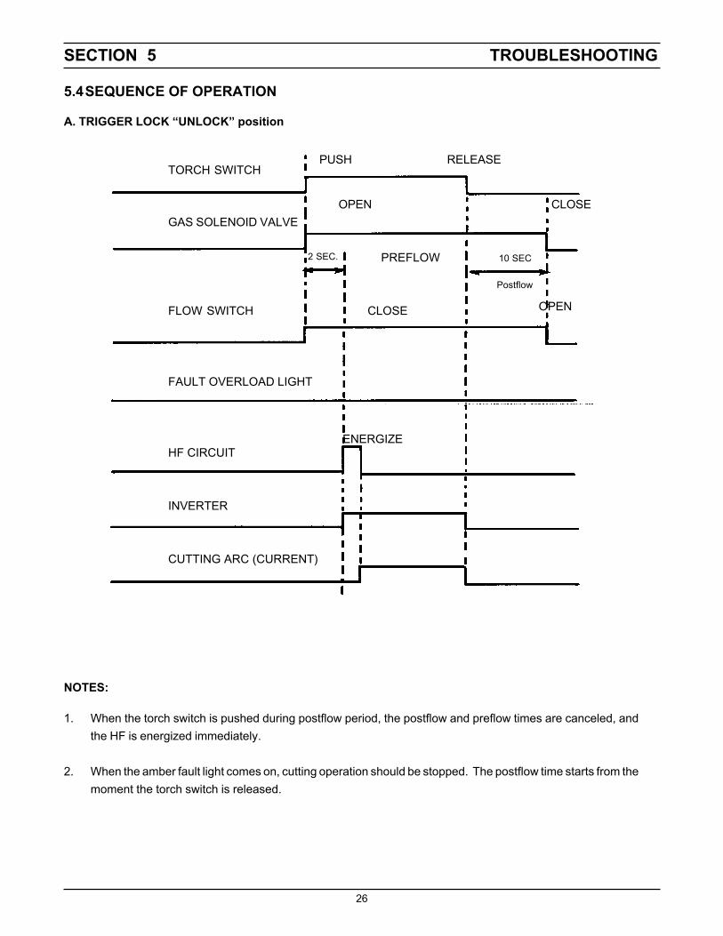
5.4SEQUENCE OF OPERATION
A. TRIGGER LOCK “UNLOCK” position
PUSH RELEASE
ENERGIZE
NOTES:
1. When the torch switch is pushed during postflow period, the postflow and preflow times are canceled, andthe HF is energized immediately.
2. When the amber fault light comes on, cutting operation should be stopped. The postflow time starts from themoment the torch switch is released.
10 SEC
Postflow
OPEN
2 SEC.

SECTION 5 TROUBLESHOOTING
27
10 SEC
PUSH RELEASE PUSH RELEASE TORCH SWITCH
OPEN CLOSE GAS SOLENOID VALVE
POSTFLOW CLOSE OPEN
FLOW SWITCH
FAULT LIGHT
HF CIRCUIT
INVERTER
CUTTING ARC (CURRENT)
B. TRIGGER LOCK "LOCK" position
ENERGIZE
NOTES:
1. When the torch switch is pushed during postflow period, the postflow time is reset, the preflow time is canceled,and the HF is energized immediately.
2. When the red fault light comes on, cutting operation should be stopped. The postflow time starts from the momentthe torch switch is released.
3. FAULT light is on during second "turn-off" trigger only. This does not affect performance in any way.
PREFLOW
Postflow
2 SEC.

28
D-37567
Figu
re 5
-1. S
chem
atic
Dia
gram
, PC
M-1
125,
208
/230
V, 5
0/60
Hz,
1 a
nd 3
-Pha
se

29
D-37568
Figu
re 5
-2A
. Wiri
ng D
iagr
am (S
heet
1 o
f 2),
PCM
-112
5, 2
08/2
30V,
50/
60 H
z, 1
and
3-P
hase

30
D-37568
Figu
re 5
-2. W
iring
Dia
gram
(She
et 2
of 2
), PC
M-1
125,
208
/230
V, 5
0/60
Hz,
1 a
nd 3
-Pha
se

31D-37569
Figu
re 5
-3. S
chem
atic
Dia
gram
, PC
M-1
125,
460
V, 5
0/60
Hz,
3-P
hase

32
D-37570
Figu
re 5
-4A
. Wiri
ng D
iagr
am, (
Shee
t 1 o
f 2) P
CM
-112
5, 4
60V,
50/
60 H
z, 3
-Pha
se

33D-37570
Figu
re 5
-4B
. Wiri
ng D
iagr
am, (
Shee
t 2 o
f 2) P
CM
-112
5, 4
60V,
50/
60 H
z, 3
-Pha
se
34
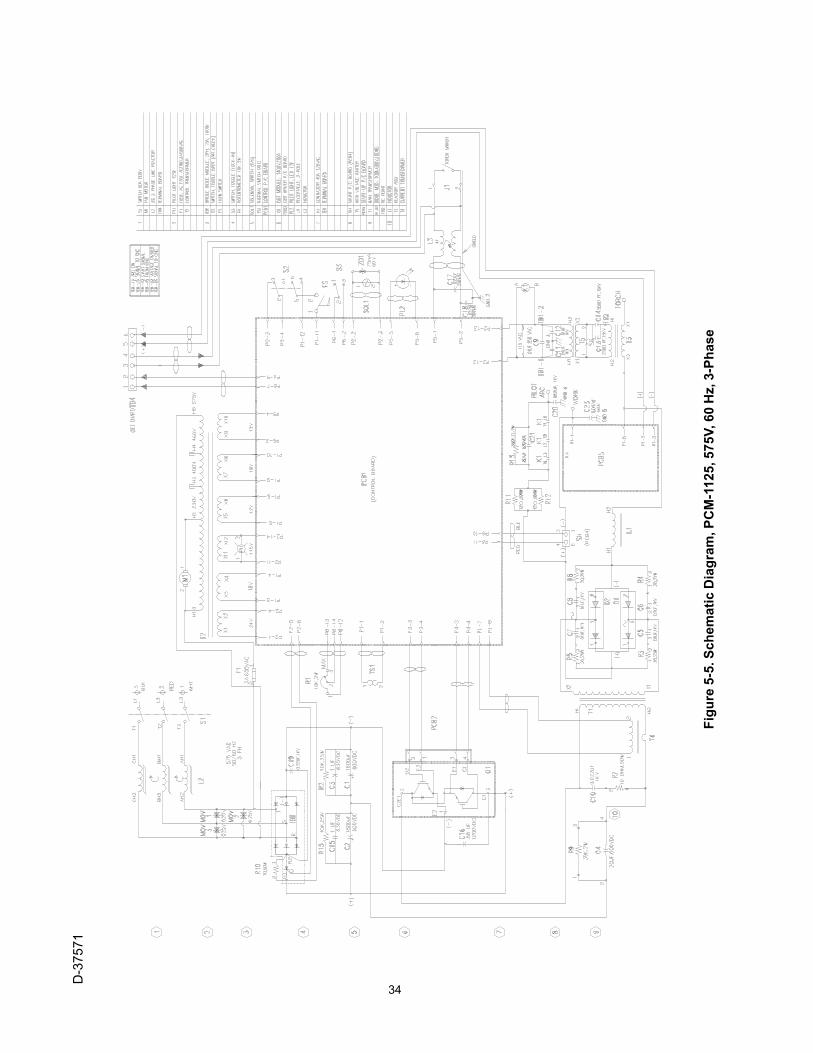
D-37571
Figu
re 5
-5. S
chem
atic
Dia
gram
, PC
M-1
125,
575
V, 6
0 H
z, 3
-Pha
se

35D-37572
Figu
re 5
-6A
. Wiri
ng D
iagr
am, (
Shee
t 1 o
f 2) P
CM
-112
5, 5
75V,
60
Hz,
3-P
hase

36
D-37572
Figu
re 5
-6B
. Wiri
ng D
iagr
am, (
Shee
t 2 o
f 2) P
CM
-112
5, 5
75V,
60
Hz,
3-P
hase
SECTION 6 REPLACEMENT PARTS
37
6.1 GENERAL
Replacement Parts are illustrated on the following fig-ures. When ordering replacement parts, order by partnumber and part name.
208/230 V, 50/60 Hz, 1 or 3-phase ............ P/N 37495460 V, 50/60 Hz, 3-phase .......................... P/N 37497575 V, 60 Hz, 3-phase ............................... P/N 37499
Always provide the series or serial number of the unit onwhich the parts will be used. The serial number isstamped on the unit nameplate.
6.2 ORDERING
To assure proper operation, it is recommended that onlygenuine ESAB parts and products be used with thisequipment. The use of non-ESAB parts may void yourwarranty.
Replacement parts may be ordered from your ESABdistributor or from:
ESAB Welding & Cutting ProductsAttn: Customer Service Dept.P.O. Box 100545, 411 S. Ebenezer RoadFlorence, SC 29501-0545
Be sure to indicate any special shipping instructionswhen ordering replacement parts.
Refer to the Communication Guide located on the lastpage of the manual for a list of customer service phonenumbers.
6.3 LITERATURE REVISIONSREVISIONS to prior issue dated November, 1998incorporated into this issue:
Pg. 2, Added Section 6.3 Literature RevisionsPg. 14, Text Change, PCM-875 to PCM-1125Pg. 15, Text Change, PCM-875 to PCM-1125Pg. 28-36, Improved legibility of diagramsPg. 37, Added, 6.3 Literature Revisions informationPg. 43, Item No. 97, P/N Correction, 32969 to 37669Pg. 45, Item No. 111, Qty, Correction, (1) to 2Pg. 45, Item No. 126, P/N Correction, 32969 to 37669

SECTION 6 REPLACEMENT PARTS
38
Fig. 6-1. PCM-1125 Power Source, Front View
Item Qty Part CircuitNo. Req. No. Description Symbol
1 1 13730611 KNOB2 1 2062018 POT. 10K 2W (NOMEX INSUL - 676876 R13 1 673213 SWITCH TOGGLE SPST 2 POS 15 A 125 V S34 2 951474 SWITCH SEAL BLACK5 1 634518 SWITCH TOGGLE DPDT 2 POS 15 A 125 V S26 1 951754 LAMP LED YEL 12 V PL27 1 951526 LAMP NEON WHITE PL18 2 993426 GROMMET RUBBER 1.50 ID x 1.76 OD9 1 21711 GAUGE 1.50 160 PSI WHITE10 1 23602576 STRAIN RELIEF EYCO #121411 1 680560 WORK CABLE 25 FT. . (Not Shown)12 4 182W12 FOOT RUBBER13 1 37556GY CHASSIS PCM-112514 1 36330YL DOOR ACCESS YEL15 1 954008 LABEL WARNING HI VOLTAGE16 2 13734588 LABEL ESAB
3, 4
1, 2
5, 46
7
8, 9
16
10, 11
15
8
14
12 13
6.4 PARTS DIAGRAMS & LISTS

SECTION 6 REPLACEMENT PARTS
39
Item Qty Part CircuitNo. Req. No. Description Symbol
21 2 951185 BRIDGE 100ADC 100NS 600 V (includes PAD - 951518) D1, 222 1 952002 CORE SATURABLE L323 1 952208 STANDOFF INS. TB324 1 36731 BUSBAR NEG25 2 952237 CAPACITOR 1800µf 450VDC C1, 226 2 994674 GROMMET STRIP27 2 38052 PCB ASS'Y 1GBT DRIVER BOARD PCB2, 328 1 36822 HOSE AY B/A-2X 1/4NPT RUB 2 FT29 1 36730 BUSBAR POS30 1 951028 CAPACITOR 1µf 630VDC (Not shown - see wiring) C331 1 950487 TERM BLOCK 2 POS TB532 1 952235 MODULE INPUT BRIDGE/SCR (includes PAD - 952280) IBR33 1 2062282 CAPACITOR .22µf 1KV (See wiring) C1934 3 951321 METAL OXIDE VARISTOR 275 V (See wiring) MOV1, 2, 335 2 952873 IGBT 600 V 200 A includes (PAD - 951191) Q1, 136 2 17750010 RESISTOR 50 W 10 OHM (PAD - 951194) R737 1 32958 CURRENT TRANSFORMER ASS'Y T438 1 952255 CAPACITOR 40 µf 400 VDC C439 1 950711 THERMAL SWITCH 194°F TS140 4 17721020 RESISTOR 24 W 20 OHMS (PAD 951193) r3, 4, 5, 641 1 951202 FLOW SWITCH .25 GPM FS42 2 951940 CAPACITOR 1µf 630W VDC C15, 1643 1 952887 HEATSINK44 1 950249 SOL. VALVE 1/4NPT 165 PSI 24 VAC SOL145 1 951471 DIODE ZENER 60 V 75 MA (See Wiring) ZD146 1 17250010 RESISTOR WW FIXED 50 W 10 OHM R1047 2 37562 BUSBAR OBR48 4 951313 CAPACITOR PULSE 0.01µf 1 KV C5, 6, 7, 849 1 951314 CAPACITOR .022µf 1 KV C10
Fig. 6-2. PCM-1125 Power Source, Left Side View (208/230)
3546
36, 49 37 38 39 40 41 42 43 44, 45
21
22
23
24
25, 262726
25, 26
29, 30
31
32, 33, 34

SECTION 6 REPLACEMENT PARTS
40
596061
56, 57, 58
62
63
64, 65, 66
7767, 79A 68 69, 70 71 72, 78, 79 73 74 75, 76
51
52
53
54
55
56, 57, 58
Fig. 6-3. PCM-1125 Power Source, Left Side View (460/575)
SECTION 6 REPLACEMENT PARTS
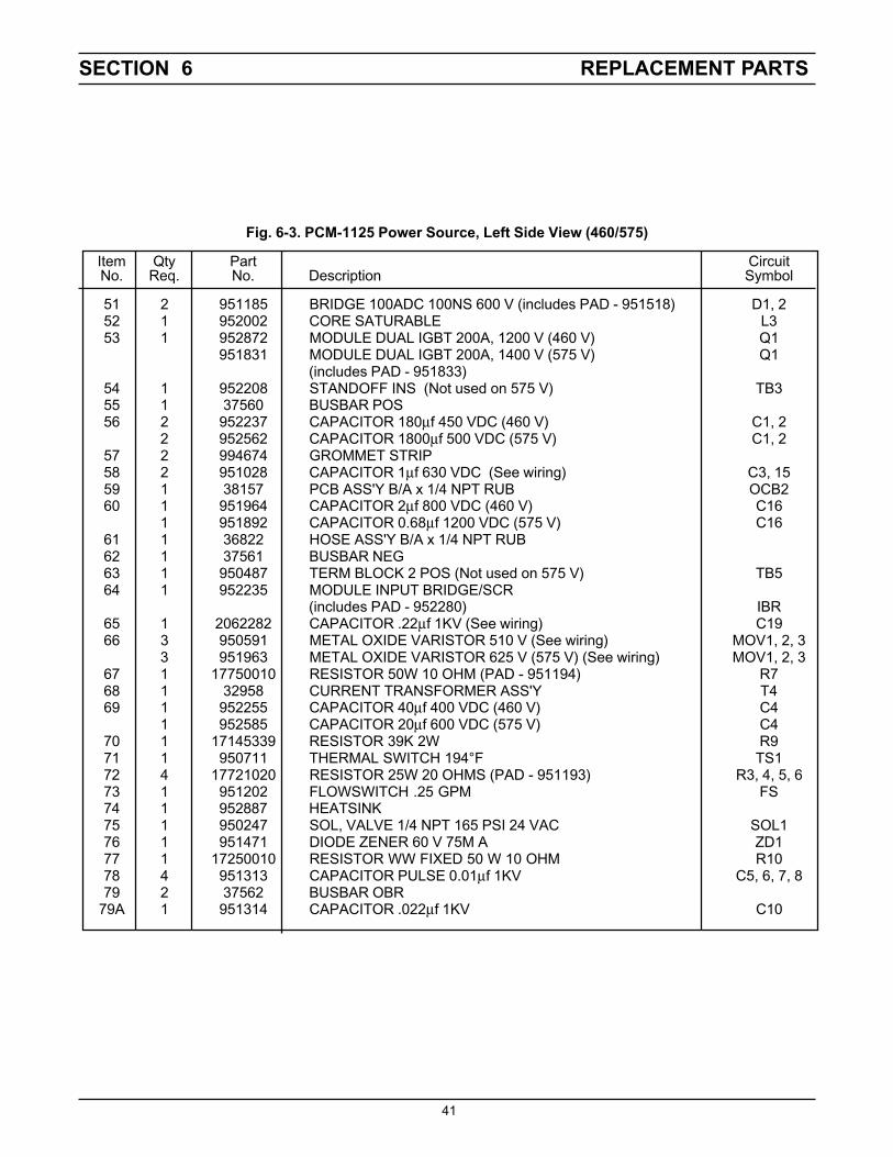
41
Fig. 6-3. PCM-1125 Power Source, Left Side View (460/575)
Item Qty Part CircuitNo. Req. No. Description Symbol
51 2 951185 BRIDGE 100ADC 100NS 600 V (includes PAD - 951518) D1, 252 1 952002 CORE SATURABLE L353 1 952872 MODULE DUAL IGBT 200A, 1200 V (460 V) Q1
951831 MODULE DUAL IGBT 200A, 1400 V (575 V) Q1(includes PAD - 951833)
54 1 952208 STANDOFF INS (Not used on 575 V) TB355 1 37560 BUSBAR POS56 2 952237 CAPACITOR 180µf 450 VDC (460 V) C1, 2
2 952562 CAPACITOR 1800µf 500 VDC (575 V) C1, 257 2 994674 GROMMET STRIP58 2 951028 CAPACITOR 1µf 630 VDC (See wiring) C3, 1559 1 38157 PCB ASS'Y B/A x 1/4 NPT RUB OCB260 1 951964 CAPACITOR 2µf 800 VDC (460 V) C16
1 951892 CAPACITOR 0.68µf 1200 VDC (575 V) C1661 1 36822 HOSE ASS'Y B/A x 1/4 NPT RUB62 1 37561 BUSBAR NEG63 1 950487 TERM BLOCK 2 POS (Not used on 575 V) TB564 1 952235 MODULE INPUT BRIDGE/SCR
(includes PAD - 952280) IBR65 1 2062282 CAPACITOR .22µf 1KV (See wiring) C1966 3 950591 METAL OXIDE VARISTOR 510 V (See wiring) MOV1, 2, 3
3 951963 METAL OXIDE VARISTOR 625 V (575 V) (See wiring) MOV1, 2, 367 1 17750010 RESISTOR 50W 10 OHM (PAD - 951194) R768 1 32958 CURRENT TRANSFORMER ASS'Y T469 1 952255 CAPACITOR 40µf 400 VDC (460 V) C4
1 952585 CAPACITOR 20µf 600 VDC (575 V) C470 1 17145339 RESISTOR 39K 2W R971 1 950711 THERMAL SWITCH 194°F TS172 4 17721020 RESISTOR 25W 20 OHMS (PAD - 951193) R3, 4, 5, 673 1 951202 FLOWSWITCH .25 GPM FS74 1 952887 HEATSINK75 1 950247 SOL, VALVE 1/4 NPT 165 PSI 24 VAC SOL176 1 951471 DIODE ZENER 60 V 75M A ZD177 1 17250010 RESISTOR WW FIXED 50 W 10 OHM R1078 4 951313 CAPACITOR PULSE 0.01µf 1KV C5, 6, 7, 879 2 37562 BUSBAR OBR
79A 1 951314 CAPACITOR .022µf 1KV C10

SECTION 6 REPLACEMENT PARTS
42
90, 9189 88
87 8685
81
80
101, 102, 103
82, 83, 84100
98, 991049796
95
94, 105
93
92
Fig. 6-4. PCM-1125 Power Source, Right Side View (208/230)

SECTION 6 REPLACEMENT PARTS
43
Fig. 6-4. PCM-1125 Power Source, Right Side View (208/230)
Item Qty. Part CircuitNo. Req. No. Description Symbol
80 1 35940 CONTROL TRANSFORMER ASS'Y T281 2 17300012 RESISTOR 300W 12 OHM R11, 1282 1 673458 CONTACTOR 3 POLE 110 VAC 40 A K183 1 952557 CAPACITOR .82µf 630 VDC (See Wiring) C21, 2284 2 17130433 RESISTOR, CM FILM AL 1W 330K (See Wiring) R1385 1 23604891 LABEL WARNING HI VOLTAGE RED86 1 952232 INDUCTOR PFC L287 1 38155 CONTROL BOARD ASS'Y PCB188 1 37603 MAIN TRANSFORMER ASS'Y T189 2 951469 CAPACITOR .022µf 250 VAC (See Wiring) C17, 1890 1 31488 SHUNT BOARD ASS'Y PCB491 1 951515 CAPACITOR .047µf 660 VAC C2392 1 38039 START UP BOARD ASS'Y PCB593 1 952233 INDUCTOR OUTPUT L194 1 36721 BUSBAR OUTPUT95 1 182W64 LOCK TWIST MIDGET J196 1 36717 BRACKET OUTPUT97 1 37669 REACTOR ASS'Y HI FREQ. T398 1 36431 SPARK GAP ASS'Y SG99 2 951342 CAPACITOR 2500pf 15 K V C13, 14100 1 951179 TRANSFORMER HI VOLTAGE T5101 1 950487 TERM. BLOCK 2 POS 20 A TB1102 2 672348 CAPACITOR .01µf 1KV (See wiring) C11, 12103 1 952204 CAPACITOR .01µf 250 VAC (See wiring) C9104 1 36718 BOX HI FREQ.105 1 951314 CAPACITOR .022µF 1K V C20

SECTION 6 REPLACEMENT PARTS
44
119, 120
118
117
116
115
111
112, 113, 114
110
133
130, 131, 132129127, 128134126125
124
123, 135
122
121
Fig. 6-5. PCM-1125 Power Source, Right Side View (460/575 V)

SECTION 6 REPLACEMENT PARTS
45
Item Qty. Part CircuitNo. Req. No. Description Symbol
110 1 32914 CONTROL TRANSFORMER ASS'Y T2111 2 17300012 RESISTOR 300 W 12 OHM R11, 12112 1 673458 CONTACTOR 3 POLE 110VAC 40 A K1113 2 952557 CAPACITOR .82µf 630 VDC (See wiring) C21114 2 17130433 RESISTOR CM FILM AL 1W 330K (See wiring) R13115 1 23604891 LABEL WARNING HI VOLTAGE RED116 1 38155 CONTROL BOARD ASS'Y PCB1117 1 37603 MAIN TRANSFORMER ASS'Y (460 V) T1
1 36599 MAIN TRANSFORMER ASS'Y (575 V) T1118 2 951469 CAPACITOR .022µf 250 VAC (See wiring) C17, 18119 1 31488 SHUNT BOARD ASS'Y PCB4120 1 951515 CAPACITOR .047µf 660 VAC (See wiring) C23121 1 38039 START UP BOARD ASS'Y PCB5122 1 952233 INDUCTOR OUTPUT L1123 1 36721 BUSBAR OUTPUT124 1 182W64 LOCK TWIST MIDJET J1125 1 36717 BRACKET OUTPUT KYDEX126 1 37669 REACTOR ASS'Y HI FREQ. T3127 1 36431 SPARK GAP ASS'Y SG128 2 951342 CAPACITOR 2500pf 15 K V C13, 14129 1 951179 TRANSFORMER HI VOLTAGE T5130 1 950487 TERM. BLOCK 2 POS 20 A TB1131 2 672348 CAPACITOR .01µf 1KV (See wiring) C11, 12132 1 952204 CAPACITOR .01µf 250 VAC (See wiring) C9133 1 952213 REACTOR 3PH LINE 12 A L2134 1 36718 BOX HI FREQ135 1 951314 CAPACITOR .022µf 1K V C20
Fig. 6-5. PCM-1125 Power Source, Right Side View (460/575 V)
SECTION 6 REPLACEMENT PARTS
46
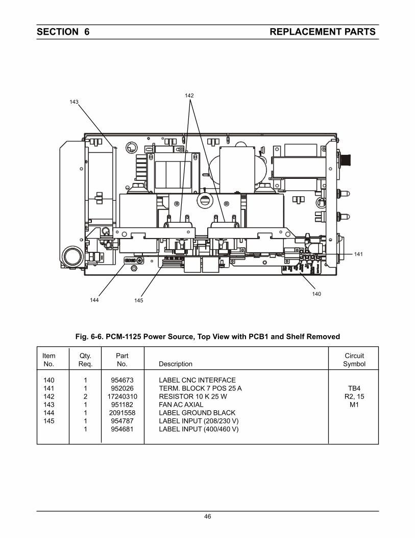
Item Qty. Part CircuitNo. Req. No. Description Symbol
140 1 954673 LABEL CNC INTERFACE141 1 952026 TERM. BLOCK 7 POS 25 A TB4142 2 17240310 RESISTOR 10 K 25 W R2, 15143 1 951182 FAN AC AXIAL M1144 1 2091558 LABEL GROUND BLACK145 1 954787 LABEL INPUT (208/230 V)
1 954681 LABEL INPUT (400/460 V)
Fig. 6-6. PCM-1125 Power Source, Top View with PCB1 and Shelf Removed
143142
144 145140
141

SECTION 6 REPLACEMENT PARTS
47
Item Qty. Part CircuitNo. Req. No. Description Symbol
151 1 21710 FILTER REGULATOR152 1 10Z30 ADAPTOR B/A-WM x 1/4 NPTM153 2 951575 HANDLE154 1 36719YL TOP COVER YEL (ESAB)155 1 2091514 LABEL WARNING156 1 954290 LABEL WARNING157 1 954784 LABEL RATING PCM-1125 208/230
1 954785 LABEL RATING PCM-1125 4601 954786 LABEL RATING PCM-1125 575
158 2 952136 FUSE HOLDER160 1 97W63 STRAIN RELIEF161 1 37573 INPUT POWER CABLE, 6 FT 4-COND. 6AWG w/PLUG (208/230 V)
1 37574 INPUT POWER CABLE, 10 FT 4-COND. 10AWG (460/575 V)162 1 36107 SWITCH POWER 600 V 63 A S1163 1 952559 FUSE 3A FAST ACTING F1164 1 954746 LABEL FAULT INDICATOR
Fig. 6-7. PCM-1125 Power Source, Rear View
160, 161
3,4
162
158, 163
151, 152153
154, 155, 156, 164
157

F-15-482-B 2/02
IF YOU DO NOT KNOW WHOM TO CALL
Telephone: (800) ESAB-123/ Fax: (843) 664-4452/ Web:http://www.esab.com
Hours: 7:30 AM to 5:00 PM EST
A. CUSTOMER SERVICE QUESTIONS:Order Entry Product Availability Pricing DeliveryOrder Changes Saleable Goods Returns Shipping Information
Eastern Distribution Center Telephone: (800)362-7080 / Fax: (800) 634-7548
Central Distribution Center Telephone: (800)783-5360 / Fax: (800) 783-5362
Western Distribution Center Telephone: (800) 235-4012/ Fax: (888) 586-4670
B. ENGINEERING SERVICE: Telephone: (843) 664-4416 / Fax : (800) 446-5693Welding Equipment Troubleshooting Hours: 7:30 AM to 5:00 PM ESTWarranty Returns Authorized Repair Stations
C. TECHNICAL SERVICE: Telephone: (800) ESAB-123/ Fax: (843) 664-4452Part Numbers Technical Applications Hours: 8:00 AM to 5:00 PM ESTPerformance Features Technical Specifications Equipment Recommendations
D. LITERATURE REQUESTS: Telephone: (843) 664-5562 / Fax: (843) 664-5548Hours: 7:30 AM to 4:00 PM EST
E. WELDING EQUIPMENT REPAIRS: Telephone: (843) 664-4487 / Fax: (843) 664-5557Repair Estimates Repair Status Hours: 7:30 AM to 3:30 PM EST
F. WELDING EQUIPMENT TRAINING:Telephone: (843)664-4428 / Fax: (843) 679-5864Training School Information and Registrations Hours: 7:30 AM to 4:00 PM EST
G. WELDING PROCESS ASSISTANCE:Telephone: (800) ESAB-123 Hours: 7:30 AM to 4:00 PM EST
H. TECHNICAL ASST. CONSUMABLES:Telephone : (800) 933-7070 Hours: 7:30 AM to 5:00 PM EST
ESAB Welding & Cutting Products, Florence, SC Welding EquipmentCOMMUNICATION GUIDE - CUSTOMER SERVICES