pci overview - qemu · pci overview pci vs pci express. 2 ... configure a device to appear in pci...
TRANSCRIPT

Marcel ApfelbaumRed HatFebruary 09, 2016
PCI OverviewPCI vs PCI Express

2
Agenda (PCI vs PCIe)
● PCI Evolution
● Technologies overview
● Topology differences
● Configuration
● PCI Hot Plug
● Interrupts handling
3
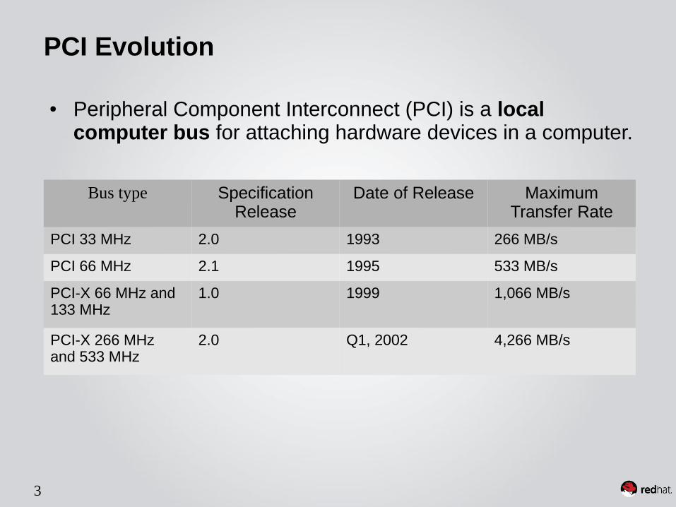
PCI Evolution
Bus type Specification Release
Date of Release Maximum Transfer Rate
PCI 33 MHz 2.0 1993 266 MB/s
PCI 66 MHz 2.1 1995 533 MB/s
PCI-X 66 MHz and 133 MHz
1.0 1999 1,066 MB/s
PCI-X 266 MHz and 533 MHz
2.0 Q1, 2002 4,266 MB/s
● Peripheral Component Interconnect (PCI) is a local computer bus for attaching hardware devices in a computer.

4
PCI Evolution
PCI Express Date Of Release
Line encoding
Transfer rate Bandwidth
Per lane X16 lane slot
1.0 Q2, 2002 8b/10b 2.5 GT/s 2 Gbit/s(250 MB/s)
32 Gbit/s(4 GB/s)
2.0 2007 8b/10b 5 GT/s 4 Gbit/s(500 MB/s)
64 Gbit/s(8 GB/s)
3.0 2010 128b/130b 8 GT/s 7.877 Gbit/s (984.6 MB/s)
126.032 Gbit/s (15.754 GB/s)
4.0 Early 2017 ? 128b/130b 16 GT/s 15.754 Gbit/s (1969.2 MB/s)
252.064 Gbit/s (31.508 GB/s)
● PCI Express (Peripheral Component Interconnect Express), officially abbreviated as PCIe, is a high-speed serial computer expansion bus standard, designed to replace the older PCI, PCI-X, and AGP bus standards.

5
Agenda (PCI vs PCIe)
● PCI Evolution
● Technologies overview
● Topology differences
● Configuration
● PCI Hot Plug
● Interrupts handling

6
Technologies overview – PCIThe basics
● PCI uses a shared bus topology to allow for communication among the different devices on the bus.
● There is a bus arbitration scheme in place for deciding who gets access to the bus and when.
● The Host Bridge provides an interconnect between the CPU/DMA and peripheral components
Host
Bridge
Bus
Device Device
CPU
DMAMemory
Controller

7
Technologies overview – PCIThe CPU point of view
● PCI devices are accessible via a fairly straightforward load-store mechanism.
● Memory address(MMIO) space● I/O address spaces● Configuration space.

8
Technologies overview – PCIBus traffic
● Command traffic (configuration)
● Read/Write traffic

9
Technologies overview – PCIPCI to PCI Bridges
● Maximum 32 multi-function devices per bus.
● A PCI-to-PCI bridge provides a connection path between two independent PCI buses.
● A bridge has two PCI interfaces, the primary and secondary.
10
Technologies overview – PCIPCI limitations
● Its highly parallel shared-bus architecture holds it back by limiting its bus speed and scalability.
● Its simple, load-store, flat memory-based communications model is less robust and extensible than a routed, packet-based model.
● PCI-X: wider and faster, but still outdated.

11
Technologies overview – PCIeThe basics
● PCIe's most obvious improvement over PCI is its point-to-point bus topology.
● Each device sits on its own dedicated bus, which in PCIe lingo is called a link.
Root (Host)
Bus
Device DeviceDevice
Root (Host)
Device
DeviceDevice Switch
PCI vs PCIe

12
Technologies overview – PCIeLinks and lanes
● A lane represents a set of differential signal pairs (one pair for Tx, one pair for Rx).
● A link represents a dual-simplex communications channel between two components.
● To scale bandwidth, a link may aggregate multiple lanes denoted by xN (x1, x2, x4, x8, x12, x16, and x32).
13
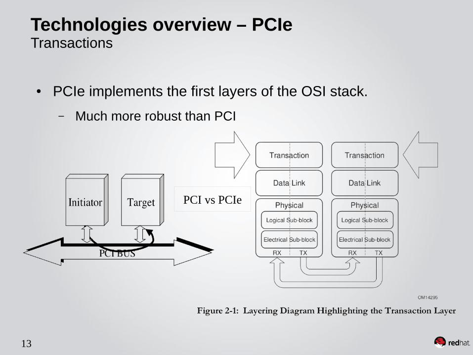
Technologies overview – PCIeTransactions
● PCIe implements the first layers of the OSI stack.
– Much more robust than PCI
PCI vs PCIe

14
Technologies overview – PCIeSwitches
● A Switch is defined as a logical assembly of multiple virtual PCI-to-PCI Bridge devices.

15
Agenda (PCI vs PCIe)
● PCI Evolution
● Technologies overview
● Topology differences
● Configuration
● PCI Hot Plug
● Interrupts handling

16
Topology - PCI

17
Topology - PCIe

18
Topology – PCIeRoot Complex location

19
Agenda (PCI vs PCIe)
● PCI Evolution
● Technologies overview
● Topology differences
● Configuration
● PCI Hot Plug
● Interrupts handling

20
Configuration PCI Configuration space triggering
● I/O mapped
● Addresses identical across machines
● Only supports 256 bytes/device
● Only supports 256 buses

21
Configuration PCI Configuration space

22
Configuration PCI Configuration – Command register
● Provides control over a device's ability to generate and respond to PCI cycles.
● 0 => device is logically disconnected from the PCI bus.

23
Configuration PCI Configuration – Status register
● The Status register is used to record status information for PCI bus related events.
● Devices may not need to implement all bits, depending on device functionality.

24
Configuration PCI Configuration – Capabilities
● A set of registers added to a linked list
● Enabled if “Capabilities” bit in Status Register is “ON”
● Capability Examples:
– MSI / MSI-X
– PCI-X
– PCIe

25
Configuration PCI Configuration – Base Address Registers (BARs)
● BAR Dual usage:
– Used to determine how much memory space or I/O space the device requires.
– Stores the base address of the memory region which is used to access the device registers.

26
Configuration Demo

27
Configuration Configuration space triggering – PCIe (ECAM)
● Memory Mapped
● Supports 4K bytes/device
– Each device has its own 4K memory page.
● Requires up to 28 bits of memory
– 256 MB
● Supports 256 buses per base address.

28
Configuration PCIe Configuration space
MMConfig 2

29
Configuration PCIe Configuration – PCIe Extended Capabilities
● It is not the PCI Express “capability”.
● Begins at offset 100h.
● Resembles PCI Capability structure.

30
Configuration PCIe Configuration – ARI Extended Capability
● ARI (Alternative Routing-ID Interpretation) Device
● Motivation
– PCI: 32 dev * 8 functions per bus
– PCIe: 1 dev * 8 functions per bus
● Device is implied 0
– <bus, device, function> replaced by <bus, function>

31
Configuration PCIe Configuration – SR-IOV Extended Capability
● Configure a device to appear in PCI configuration space as multiple functions.
● Two new function types:
– PFs: full functions
– Vfs: “lightweight” functions
● Leverages ... ARI

32
Configuration PCIe Configuration – Other Extended Capabilities
● Function Level Reset (FLR)
● Advanced Error Reporting (AER)
● Access Control Services (ACS)
● ...

33
Configuration Enumeration & Resources allocation

34
Configuration Multiple host bridges / Root complexes
● NUMA – how servers scales up● A PCI Host Bridge can be connected to a single NUMA node● Device assignment for a VM with multiple NUMA nodes

35
Agenda (PCI vs PCIe)
● PCI Evolution
● Technologies overview
● Topology differences
● Configuration
● PCI Hot Plug
● Interrupts handling

36
● PCI Hot Plug (PHP) is the concept of removing or inserting a standard PCI adapter card from a system without interrupting normal system operation or powering-down the system as a whole.
● History
– 1997: PCI Hot Plug introduced
– 2001: Standardized Hot Plug Usage Model and the hot plug controller(SHPC)
– 2002: PCIe Hot plug developed as part of PCIe base specification
● ACPI Hot plug, as part of ACPI spec
– Out of the scope of this presentation
PCI Hot PlugIntroduction

37
The SHPC must be integrated into a PCI-to-PCI bridge or host bridge.
Hot Plug controllers must:
● assert and deassert the reset signal to the PCI Express card
● remove or apply power to the card connector
● turn on or turn off the Power and Attention Indicators associated with a specific card connector to draw the user's attention to the connector and advertise whether power is applied to the slot.
● Monitor slot events (e.g. card removal) and report these events to software via interrupts.
PCI Hot PlugSHPC

38
PCI Hot Plug
SHPC - PCI vs PCIe

39
User Interface Allows user to request hot-plugoperations
Hot-Plug System Driver / Hot-Plug Service
Receives requests issued by the OS and Interacts with the hardware Hot-Plug Controllers to accomplish requests.● provide slot identifiers● turn device On/Off● turn Attention Indicator On/Off● set current state of slot On/Off
Device Driver Hot-Plug-specific capabilities must be incorporated in a Hot-Plug capable device driver● support for the Quiesce command
Firmware Ensure unused IO/MEM regions remain for the use of the new PCI devices
PCI Hot PlugSoftware elements of Standard Hot Plug Usage Model

40
Hot-Plug Controller Receives and processes commands issued by the Hot-Plug Device Driver
Power Indicator Indicates the slot/card for service
Attention Indicator The Attention Indicator is used to draw the attention of the operator or to indicate a Hot Plug problem or failure.
Attention Button Allows user to request hot-plugoperations
Manually-operated Retention Latch(MRL)
Holds add-in cards in place
MRL Sensor Allows the port and system software todetect the MRL being opened
Electromechanical Interlock Prevents removal of add-in cards whileslot is powered
PCI Hot PlugHardware Elements of Standard Hot Plug Usage Model

41
PCI Hot PlugHardware Elements of Standard Hot Plug Usage Model

42
● The operator installs the card and secures the MRL
● The MRL sensor(if present), causes a system interrupt to be sent to the Root Complex signaling the SHPC driver that the latch is closed
● User initiates hot add using Attention Button or UI
● The SHPC driver causes the slot's Power Indicator to blink for 5 seconds, this being the window to cancel the operation and also the time for the software to validate the request.
● The SHPC driver issues a request to the hot plug controller to power on the slot
● Once link training is complete, the Hot plug driver causes re-enumeration of the slot bus; The hot added device is found, configured and driver is loaded.
PCI Hot PlugHot Add Sequence
43
● The user requests hot removal by pressing the Attention Button on the corresponding slot or by a software request.
● The SHPC detects this event and delivers an interrupt to the Root Complex. As a result of the interrupt, the Hot Plug System Driver reads slot status information and detects the Attention Button request.
● Power LED blinks to indicate transition state. The operator is granted a 5 second interval to cancel the request and the Hot Plug software validates the request.
● OS offlines the PCI Express device: the Hot-Plug System Driver commands the card's device driver to quiesce.
● Next, software commands the Hot Plug Controller to turn the slot off.
● User opens the MRL and the card can now be removed.
● The OS deallocates the memory space, IO space, interrupt line, etc.
PCI Hot PlugHot Remove Sequence

44
● PCI Express allows buttons/indicators to be placed either on the chassis or the card
– Buttons/Indicators on card can further be handled side-band or in-band
● Buttons/Indicators implemented on the chassis are indicated using Slot Capabilities Register
– Other Hot Plug related Registers: Slot Control Register, Slot Status Register
● Buttons/Indicators implemented on the card are indicated using Device Capabilities Register
PCI Hot PlugHot Plug Registers

45
Agenda (PCI vs PCIe)
● PCI Evolution
● Technologies overview
● Topology differences
● Configuration
● PCI Hot Plug
● Interrupts handling

46
Interrupts handlingLegacy interrupts
● Legacy interrupts are dedicated side-band signals.
● Multiple interrupt signals may share a single physical line.
47
Interrupts handlingMSI
● In-band messages are implemented as memory writes to an address with a data value, as specified by software.
– Required for PCI Express devices, optional for PCI devices
– Maximum of 32 MSIs per function
● MSI has a number of distinct advantages over INTx
– Sharing of interrupt vectors is eliminated
– Devices may have multiple interrupts per function

48
Interrupts handlingMSI capability structure
● To request service, an MSI function writes the contents of the Message Data register to the address specified by the contents of the Message Address register.
● Per-vector masking (optional) is managed through a mask and pending bit pair per MSI vector

49
Interrupts handlingMSI-X
● MSI-X has the same features as MSI, the key differences are:
– Maximum of 2048 MSI-Xs per function
– MMIO region required for MSI-X tables and Pending Bit Arrays
– Per function vector masking and per vector masking (optional for MSI)

50
Interrupts handlingMSI-X capability structure
● The capability structure points to:
– A MSI-X Table structure
– A Pending Bit Array (PBA) structure.
● Each structure is mapped by a BAR.

Thank you!