passive sensors fabricated by and systems environments library/research/coal/cross... · subtask...
TRANSCRIPT

1
Passive Wireless Sensors Fabricated by Direct‐Writing for Temperature and Health Monitoring of Energy Systems in Harsh‐Environments
Team: Dr. Daryl Reynoldsa
Dr. Edward M. SabolskybDr. Kostas Sierrosb
aLane Department of Computer Science and Electrical EngineeringbDepartment of Mechanical and Aerospace Engineering
West Virginia University (WVU)

Outline1) Background2) Vision of Technology3) Statement of project objective4) Description of team 5) Task descriptions (with approach and previous
work)6) Important project milestones
2

Background‐ Harsh Environment Sensing Needs
Online monitoring of energy systems in extreme conditions is required for mining/drilling, transportation, aviation, energy, chemical synthesis, and manufacturing applications.
Harsh‐environments include: High temperature (1000oC‐2000oC) High pressure (up to 1000 psi) Various pO2 levels Corrosive conditions (molten inorganics or reactive gasses)
Ability to monitor: Temperature Stress/strain within energy or reactor components Failure events Overall health
3

Processing Vision
4
Item A represents the organic carrierfilm.
Item B represents the polymer-precursor ink (converts to anelectroceramic after heat treatment).
Item C represents a possible barrierlayer.
Item D represents printed sensorcircuit on the transfer paper.
Item E shows the pattern beingplaced upon the energy-systemcomponent.
Item F represents the pyrolysis ofthe organic carrier and bonding.
[D.]
[E.][F.]

5
Sensing Vision
Item A represents the LCR sensor and communication circuit.
Item B represents the inductor component (2D spiral) which act as acomponent for the sensor communication.
Item C represents the reader/powering antenna.
Alteration in the LCR components (due to temperature or strain changes) willresult in a shift in measureable parameters (such as resonance frequencyprofile).
[A.]
[B.][C.]

1) Investigate phase formation, sintering/grain growth, and electrical properties of polymer‐derived electroceramic composites between 500‐1700 C.
2) Define processes to direct‐write through ink‐jet and robo‐casting the electroceramic composites onto oxide and polymer surfaces.
3) Develop methods to form monolithic “peel‐and‐stick” preforms that will efficiently transfer the sensor circuit to ceramic surfaces after thermal treatment.
4) Design of passive wireless LCR circuits and receiver (reader) antennas for communication and testing at temperature up to 1700C.
5) Demonstrate the passive wireless sensor system developed for temperature and stress/strain measurements on a SOFC repeat unit and a singular gas turbine blade prototype as example applications.
Program Objectives
6

Dr. Edward M. Sabolsky (WVU Mechanical and Aerospace Engineering) will act as PI of the program (both technical and administrative), and will be responsible for ceramics processing and sensor testing.
Dr. Kostas Sierros (WVU Mechanical and Aerospace Engineering) will lead development of micro‐patterning and robo‐casting of ceramic materials, and will be the co‐developer of the printing inks and direct‐writing tasks.
Dr. Daryl Reynolds (WVU Computer Engineering) will lead the electronics design, interfacing and circuitry, in addition to the development of the passive wireless communication and testing.
Dr. Andrew Nix (WVU Mechanical and Aerospace Engineering) 15 years of experience in turbine blade testing, and he will consult on the turbine blade demonstration testing.
R&D Team
7

Task 2.0:Fabrication and Characterization of Polymer‐Derived Electroceramic
Composites.(Sabolsky)
8
Task 2.0 Objectives:
Investigate phase formation, sintering/grain growth, and electrical properties of polymer‐derived electroceramic composites between 500‐1700 C.
9

Task 2.0 Approach:
Subtask 2.1 Synthesis of Multifunctional ElectroceramicComposites through Polymer‐Derived Precursors. (Q1‐Q3)‐
Subtask 2.2 Thermal Processing of Composite Compositions.(Q1‐Q3)‐
Subtask 2.3 Composite Material Testing andCharacterization. (Q1‐Q4)‐
Full activity will not initiate until staffing completed in Jan.
10

11
Polymer‐Derived Ceramics (PDCs):

12
Polymer‐Derived Ceramics (PDCs):

13
Polymer‐Derived Ceramics and Effect of Fillers:
Inert Filler= additional inorganic particles that do not react with polymer as it decomposes.
Active Filler= additional inorganic particles that react with polymer precursor.
Cracks, porosity, and voids!

14
Active Fillers for PDCs:
Reactive additions may reduce level of shrinkage which could maintain electrical percolation and bonding to substrate.
Critical balance between transformation content, shrinkage, and printability.
Note: Current sensor application does not required full densification!

15
Few Reasons for Oxide and Silicide Additions:
1) Highly conductive interconnects can be fabricated(from metallic‐like silicide compositions (> 100 S/cm)).
2) Silicides are highly resistant to oxidation (at temperatures up to 1800C due to a passivation layer).
3) Silicides show high chemical stability (at high‐temperature (do not decompose) like many carbides and nitrides in oxygen).
4) Silicide/Oxide composites show even higher chemical and microstructure stability.
5) Heating elements, glow plugs and igniters composed of Silicide/Oxide composites have functioned in various harsh‐environments for >10,000s cycles(such as those fabricated by Saint‐Gobain, Kyocera, NGK…)

Task 3.0: Direct‐Writing, Patterning, and Transfer of the Sensor System.
(Sierros/Sabolsky)
16

Task 3.0 Objectives:
To define processes to direct‐write through ink‐jet and robo‐casting the polymer‐derived electroceramiccomposites onto oxide and polymer surfaces.
To develop a method to transfer the pattern from an organic film to a ceramic surface and bond after thermal treatment.
17

Task 3.0 Approach: Subtask 3.1 Direct‐Writing Ink Development. (Q2‐Q4)‐ Subtask 3.2 Direct‐Writing/Patterning and Drying
Characterization. (Q2‐Q6) Subtask 3.3 Thermal Processing Development and Structure
Tailoring. (Q2‐Q5)‐ Subtask 3.4 Baseline Sensor Testing and Design
Optimization. (Q3‐Q8)‐ Subtask 3.5 “Peel‐and‐Stick” Development. (Q3‐Q8)‐
18

Additive Manufacturing of Ceramics:
19

20
Shaping of Polymer‐Derived Ceramics:

Figure 2: Examples of direct writing at WVU. (a) Ag pattern for flexible electrodes ; (b) TiO2-TAHL aqueous film.
21
Robo‐casting of Electroceramic Patterns:
Figure 1: (a) Proposed approach; (b) Nozzle-based robotic deposition (NBRD) system and ink printing.
Robocasting of numerous ink formulations including;
‐ ZnO sols‐ Nanoparticle‐based Ag ‐ TiO2 aqueous solutions‐ Graphene‐ Nanoparticle C

Example: Robo‐casting of large‐area conductive Ag patterns for flexible electrodes:
22 M.A. Torres Arango, …,K. A. Sierros, Thin Solid Films (2015) In Press

Dimatix DMP-2981 uses disposable piezo inkjet cartridge.
Replaceable small capacity (1.5ml) cartridges.
Cartridge consists of 16 independently controllable nozzles which allow for 10 pl drop size.
Deposits nano-suspensions, organic fluids or metal salt solutions.
<20 cP viscosity is targeted for printing with ink jet.
Sensors and Circuits by Ink Jet Writing:
Potential Issue Achieving proper kinematic rheology criteria with PDC precursors.
35
25
= density= drop velocity= surface tensionL= nozzle diameterµ= ink viscosity

24
Transfer of Patterns to Energy Component: Process has been demonstrated for sensor components using Ag, Ni, and
oxide inks.
Potential issues: Re-dispersion of aqueous inks with water-release mechanism. Surface roughness and porosity effects on bonding (during release
and final sensor bonding). Effects of thermolysis on microstructure and sensor electrical
properties (and requirements for in-service firing).

Task 4.0: Passive Wireless Communication
Circuit Design and Testing.(Reynolds)
25
Task 4.0 Objectives:
• To design and model a passive wireless LCR circuit and receiver (reader) antennas for communication.
• To fabricate and test the sensor design and circuit at room temperature and up to 1700C.
26

Task 4.0 Approach:• Subtask 4.1: Passive Wireless Communication Circuit Design
and Testing. (Q1‐4)‐
• Subtask 4.2: Circuit Fabrication and Testing at LowerTemperatures. (Q3‐9)‐
27

28
Reynolds Group Previous Work I/IIIWake‐up signaling for wireless sensor networks:
Conventional approach: periodic polling of the communication channel;consumes lots of energy

29
Reynolds Group Previous Work II/IIIOur approach: ultra‐low power magnetic coupling for wakeup
• Considered coil gauge, resistance, turns, diameter, etc.

30
Reynolds Group Previous Work III/IIIWith low‐complexity, low‐power circuitry, we achieved order of magnitudeimprovements in energy efficiency:

31
Task 4 Proposed WorkOptimize both sides of the wireless link
• Sensor side• Frequency considerations: which frequency range(s) penetrate barriers
and provide good reader range.• HF (13.56 MHz): phone chips, short range, well standardized• UHF (902‐928 MHz): good range, small antennas, standards exist
• Optimizing antenna configurations:
(Chen, et al, IEEE Antennas and Propagation Magazine, 2013.)

32
Task 4 Proposed Work• Ring Resonators: closed or open rings in a dialectric ceramic matrix• Behaves like an LC resonant circuit• Can we achieve resonance in UFH band?• What kind of range will be achievable?
(Bilotti et al, IEEE Trans. Antennas and Propagation, 2007)

33
Task 4 Proposed Work• Reader side
• Goals• Good read range• Ease of use• Cloud connected: automatic data upload; automatic event
messaging• Reasonable cost
• Option 1: Modify off‐the‐shelf UHF readers• Run Windows Embedded• Highly capable• Expensive: $2,500+
• Option 2: UHF RFID Phone dongle• Inexpensive: $200• 1m read range

34
Task 4 Proposed Work• Option 3: Construct our own reader:
• High‐Gain Antenna
• Single Board Computer
• Display
• Housing
• Cost: < $1000

Task 5.0: Implementation of Passive Wireless Sensors in Harsh‐Environments.
(Sabolsky/Nix/Reynolds)(Nexceris/GE)
35

Task 5.0 Objectives:
• To investigate the passive wireless sensor system developed (and method of transferring sensor system) for temperature and stress/strain measurements on:– SOFC repeat unit (with Nexceris LLC)– Singular gas turbine blade prototype as example applications (with GE Global Research)
36

Task 5.0 Approach:
Subtask 5.1 Performance Evaluation of Passive WirelessSensor System at High Temperature (Q4‐Q11)‐
Subtask 5.2 Wireless Concept Demonstration for SOFCs(Q10‐Q12)‐
• Subtask 5.3 Wireless Concept Demonstration for TurbineBlades (Q10‐Q12)‐
37
38
(a)
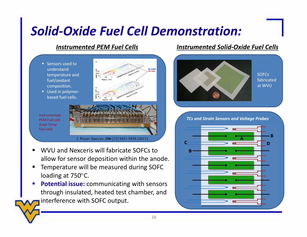
Solid‐Oxide Fuel Cell Demonstration:Instrumented PEM Fuel Cells
Sensors used to understand temperature and fuel/oxidant composition.
Used in polymer‐based fuel cells.
InstrumentedPEM Fuel cell(Low‐Temp fuel cell)
Instrumented Solid‐Oxide Fuel Cells
SOFCs fabricated at WVU
TCs and Strain Sensors and Voltage Probes
J. Power Sources.,196 [22] 9451-9458 (2011).
WVU and Nexceris will fabricate SOFCs to allow for sensor deposition within the anode.
Temperature will be measured during SOFC loading at 750C.
Potential issue: communicating with sensors through insulated, heated test chamber, and interference with SOFC output.

39
Turbine‐Blade Demonstration:GE Monitoring & Diagnotics
WVU will place an array of temperature (potentially a strain) sensors onto turbine‐blade simulant (with TBC) supplied by GE Global.
Sensors will be monitored on blade at >1200C (blade will be static, but methods to measure dynamic effects will be considered).
Targeted Goal: peel‐&‐stick on curved structure and sensor functionality at HT. Potential issue: communicating with sensors through insulated, heated test chamber.
• This funding by the U.S. Department of Energy (DOE)under contract DE‐FE0001245.
• Funding by the U.S. Department of Energy (DOE) undercontract DE‐FE0012383.
• We also would like to thank to HarbisonWalkerInternational for their support.
• We acknowledge use of the WVU Shared ResearchFacilities.
• We also would like the acknowledge Dr. Wei Ding, and Dr.Marcela Redigolo for their assistance.
40
Acknowledgments: