passive components - genton.com.t passive components.pdf · rosenberger supplies complete passive...
TRANSCRIPT

PA
SS
IVE
C
OM
PO
NE
NT
S
PASSIVE COMPONENTS
Rosenberger Asia Pacific Electronic Co., Ltd.
No.3, Anxiang Street, Block B, Tianzhu Airport Industrial Zone
Beijing, China 101300
Tel : (+86 10) 80481995
Fax : (+86 10) 80497052
Email: [email protected]
Rosenberger (Shanghai) Technology Co.,Ltd.
No. 303, Xinke Road, Qingpu Industrial Zone
Shanghai, China 201707
Tel : (+86 21) 69214567
Fax : (+86 21) 69212923
Rosenberger Asia Pacific Electronic Co., Ltd. Shanghai Division
B7, No. 509, Renqing Road, East Zone of Zhangjiang High-Tech Park
Shanghai, China 201201
Tel : (+86 21) 58995997
Fax : (+86 21) 58995594
Rosenberger Asia Pacific Electronic Co., Ltd. Dongguan Division
3rd Floor, Building E, Pingqian Industrial Park, Dongkeng Town
Dongguan, Guangdong Province, China
Tel : (+86 769) 82802098
Fax : (+86 769) 82802099
Rosenberger All rights reserved. 1st Edition, 2013
Please visit our website: www.RosenbergerAP.com
www.RosenbergerAP.com
www.RosenbergerAP.com
IntroductIon
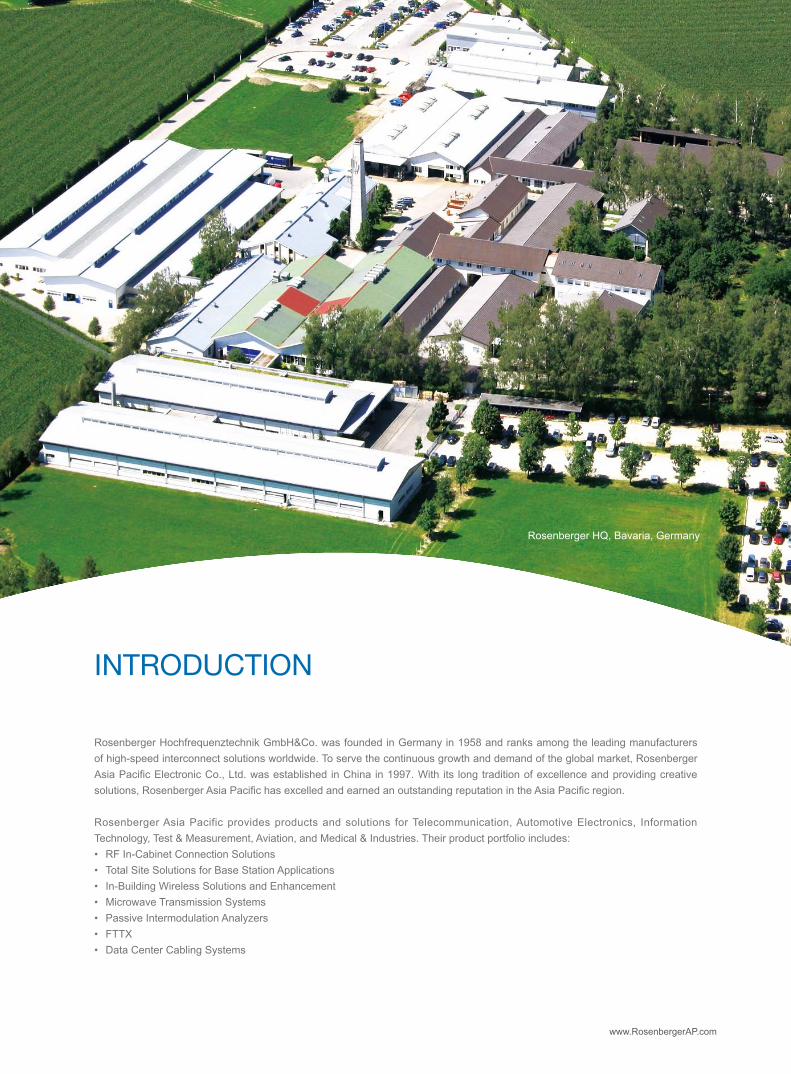
Rosenberger Hochfrequenztechnik GmbH&Co. was founded in Germany in 1958 and ranks among the leading manufacturers of high-speed interconnect solutions worldwide. To serve the continuous growth and demand of the global market, Rosenberger Asia Pacific Electronic Co., Ltd. was established in China in 1997. With its long tradition of excellence and providing creative solutions, Rosenberger Asia Pacific has excelled and earned an outstanding reputation in the Asia Pacific region.
Rosenberger Asia Pacific provides products and solutions for Telecommunication, Automotive Electronics, Information Technology, Test & Measurement, Aviation, and Medical & Industries. Their product portfolio includes:• RF In-Cabinet Connection Solutions• Total Site Solutions for Base Station Applications• In-Building Wireless Solutions and Enhancement• Microwave Transmission Systems• Passive Intermodulation Analyzers• FTTX• Data Center Cabling Systems
Rosenberger HQ, Bavaria, Germany

A
B
C
D
E
www.RosenbergerAP.com
A sales network covering the entire Asia Pacific region generates an annual turnover close to 200 million USD. Reliability and competitiveness are the cornerstones of this sustainable growth, resulting in long term partnerships with most of the leading companies in their respective industries.
Rosenberger Asia Pacific maintains 6 modern manufacturing and R&D base locations in Beijing, Shanghai, and Dongguan in China; and New Delhi in India, the largest of its kind in the Asia Pacific Region. Rosenberger Asia Pacific is an ISO 9001 quality system, ISO 14001 environmental system, and ISO/TS16949 automotive industry system certified company. Equipped with advanced machining, electronic plating, assembly and testing centers and staffed by a large group of more then 200 R&D engineers, Rosenberger Asia Pacific has developed first class production assembly lines and exercises stringent product and quality control.
Presently, Rosenberger Asia Pacific maintains a far reaching network of R&D, Production, Sales and Service which extends to the whole Asia Pacific and Middle East area. For over 50 years Rosenberger has established its brand all over the world. In the future, Rosenberger Asia Pacific will continue to provide excellent product solutions and services for its customers in the entire region.
Rosenberger Asia Pacific:
A: Beijing − Headquarters, R&D, and Production
B: Shanghai Zhangjiang − R&D and Production
C: Shanghai Qingpu − R&D and Production
D: India − R&D and Production
E: Dongguan − R&D and Production

www.RosenbergerAP.com
MISSIon StAtEMEnt
corE VAluE• Value Innovation• Customer Focus• Sustainable Growth• Social Responsibility
• Design, manufacture and deploy total solutions for telecommunication networks worldwide• Create value for our customers through innovative products, customized services and cost
effective solutions• Maintain the highest quality standards, state-of-the-art manufacturing facilities and employ
reliable supply chain management to achieve and exceed customer expectations• Be socially responsible to our community and environment • Be committed to employee's personnel development

www.RosenbergerAP.com
ProductPortFolIoS
Base Station Antenna Feeder SystemsWireless Coverage Optimization SolutionsMicrowave Backhaul SolutionsRF In-cabinet SolutionsPassive Intermodulation Measurement SystemsFTTA/FTTH Optical Fiber SolutionsOSP Fiber Optic Outdoor Plant SolutionsIn-building Optical Network Connectivity SolutionsLow Frequency Cables and ComponentsNetwork Optimization Services
Premise Network Cabling ProductsData Center/Cloud Computing SolutionsIntelligent Infrastructure Management System
Test CablesPrecision ConnectorsCalibrationsAccessories and Tools
FAKRA Connectors and Cable AssembliesHSD® System
Non-Magnetic RF Connectors Non-Magnetic RF Cable AssembliesData/RF/Power/DC Hybrid Connectors and AssembliesCustom Data/Power Connectivity SystemFiber Optic Connectivity Products
Telecommunication System Solutions
IT/Data Communication
Testing and Measurement
Automotive
Medical & Industrial
contEnt
ROSENBERGER PASSIVE COMPONENTS TECHNOLOGy
————————————————————————————————————————
COMBINERS
————————————————————————————————————————
FILTERS
————————————————————————————————————————
DUPLExERS
————————————————————————————————————————
COUPLERS
————————————————————————————————————————
SPLITTERS
————————————————————————————————————————
ATTENUATORS
————————————————————————————————————————
HyBRIDS
————————————————————————————————————————
TERMINATION LOADS
————————————————————————————————————————
POINT OF INTERFACE
————————————————————————————————————————
ROSENBERGER SERVICE
————————————————————————————————————————
06
07
20
28
33
36
39
42
46
49
53

roSEnbErgEr PASSIVE coMPonEntS tEchnology
PASSIve CoMPonenTS
0605
With the development of modern wireless communication technology such as GSM, CDMA, DCS, WLAN, UMTS, WiMAx and LTE network, more and more mobile wireless networks are deployed requiring wideband universal passive components. Rosenberger supplies complete passive components for wireless Distribution Antenna System (DAS) in the in-building coverage system including Couplers, Splitters, Hybrid Couplers, Duplexers, Filters, Diplexers and Triplexers. With the latest advanced technology of dielectric ceramic, Rosenberger offers customized high performance TE mode 2x2 and 4x4 Tx/Rx filter combiners for both TDD and FDD LTE systems.
OUTLINE

coMbInErS
• Suitable for co-siting purposes• Reduce infrastructure cost• Enable feeder sharing• Suitable for indoor or outdoor applications• Available as a single unit, or for Xpol antennas
as a double unit
• Can be used as a combiner or in reciprocal function
• Wall or mast mounting• Low insertion loss• DC stop available as an accessory
PASSIve CoMPonenTS

coMbInEr PArt nuMbErIng ForMAt
1CB: Cavity CombinerDCB: Dual Cavity Combiner
22: 2 way3: 3 way…
3C: CDMA800MHzG: GSM900MHz D: DCS1800MHz P: PCS1900MHz U: UMTS2100MHzPOI: POI
4NF: N Connector, Female DF: DIN Connector, Female NM: N Connector, Male DM: DIN Connector, Male SF: SMA Connector, Female SM: SMA Connector, Male
5Series No.
0807
1 2 3 4 5X X - X X - X X - X X - X X
Note: The type of xx3 can be single or multiple, for example: CB-3-GDU-DF-04, GDU consists of G, D and U, means the combiner supports GSM900, DCS 1800, and UMTS2100.

Main Features• Compact, low weight• Low PIM• High reliability• Easy installation
806-960MHz & 1710-2170MHz Combiner
Pn. CB-AB2-101Electrical Specifications
Frequency CH1: 806 ~ 960MHz CH2: 1710 ~ 2170MHz
Return loss ≤ -20dB
Insertion loss ≤ 0.4dB
Ripple ≤ 0.3dB
Isolation CH1 ←→ CH2 ≥ 80dB
Power handling 200W
Intermodulation (3rd order) ≤ -140dBc @ 2 x 20 W
Impedance 50 Ω
Environmental Specifications
Operating temperature range -25°C ~ +70°C
Storage temperature range -40°C ~ +85°C
Relative humidity 5% ~ 95%
Barometric pressure 55KPa ~106 KPa
Application Indoor
Mechanical Specifications
Dimension 199 x 77 x 44 (mm)
Weight 2.0kg
Connector type N female
Mounting Plane mount
Packing 1 Pce in box
general combiner (Indoor)

Main Features• Compact, low weight• Low PIM• High reliability• Easy installation
800-960MHz & 1710-1880MHz &1920~2170 Combiner
Pn. CB-2-DU-nF-01Electrical Specifications
Frequency CH1: 1710 ~ 1880MHzCH2: 1920 ~ 2170MHz
Return loss ≤ -20dB
Insertion loss ≤ 0.6dB
Isolation CH1 ←→ CH2 80dB
Power handling 200 W
Intermodulation (3rd order) ≤ -150dBc @ 2 x 20 W
Impedance 50 Ω
Environmental Specifications
Operating temperature range -10°C ~ +65°C
Storage temperature range -40°C ~ +85°C
Relative humidity 5% ~ 95%
Barometric pressure 55KPa ~106 KPa
Application Indoor
Mechanical Specifications
Dimension 176 x 142 x 41 (mm)
Weight 2.0kg
Connector type N female
Packing 1 Pce in box
1009

Main Features• Compact, low weight• Triplexer• High reliability• Easy installation
Pn. CB-3-GDU-nF-01Electrical Specifications
FrequencyCH1: 800 ~ 960MHzCH2: 1710 ~ 1880MHzCH3: 1920 ~ 2170MHz
Return loss ≤ -20dB
Insertion loss ≤ 0.3dB (CH1)≤ 0.5dB (CH2&CH3)
Isolation CH1 ←→ CH2 & CH3 CH2 ←→ CH3
≥ 80dB≥ 60dB
Power handling 100 W
Intermodulation (3rd order) ≤ -140dBc @ 2 x 20 W
Impedance 50 Ω
Environmental Specifications
Operating temperature range -10°C ~ +60°C
Storage temperature range -40°C ~ +85°C
Relative humidity 5% ~ 95%
Barometric pressure 55KPa ~106KPa
Application Indoor
Mechanical Specifications
Dimension 189 × 150 × 37 (mm)
Weight 1.5kg
Connector type N female
Mounting Plane mount
Packing 1 Pce in box
800-960MHz & 1710-1880MHz &1920~2170 Combiner
Main Features• Compact, low weight• Diplexer• High reliability• Easy installation
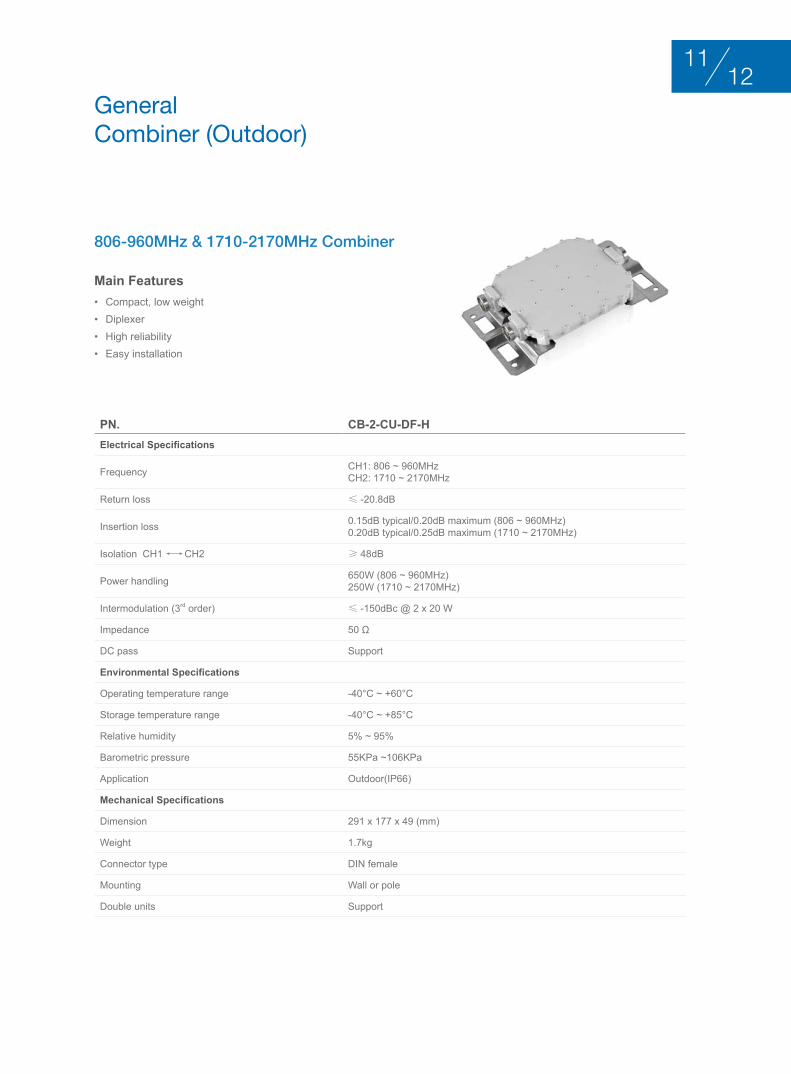
806-960MHz & 1710-2170MHz Combiner
Pn. CB-2-CU-DF-HElectrical Specifications
Frequency CH1: 806 ~ 960MHzCH2: 1710 ~ 2170MHz
Return loss ≤ -20.8dB
Insertion loss 0.15dB typical/0.20dB maximum (806 ~ 960MHz)0.20dB typical/0.25dB maximum (1710 ~ 2170MHz)
Isolation CH1 ←→ CH2 ≥ 48dB
Power handling 650W (806 ~ 960MHz)250W (1710 ~ 2170MHz)
Intermodulation (3rd order) ≤ -150dBc @ 2 x 20 W
Impedance 50 Ω
DC pass Support
Environmental Specifications
Operating temperature range -40°C ~ +60°C
Storage temperature range -40°C ~ +85°C
Relative humidity 5% ~ 95%
Barometric pressure 55KPa ~106KPa
Application Outdoor(IP66)
Mechanical Specifications
Dimension 291 x 177 x 49 (mm)
Weight 1.7kg
Connector type DIN female
Mounting Wall or pole
Double units Support
general combiner (outdoor)
1211
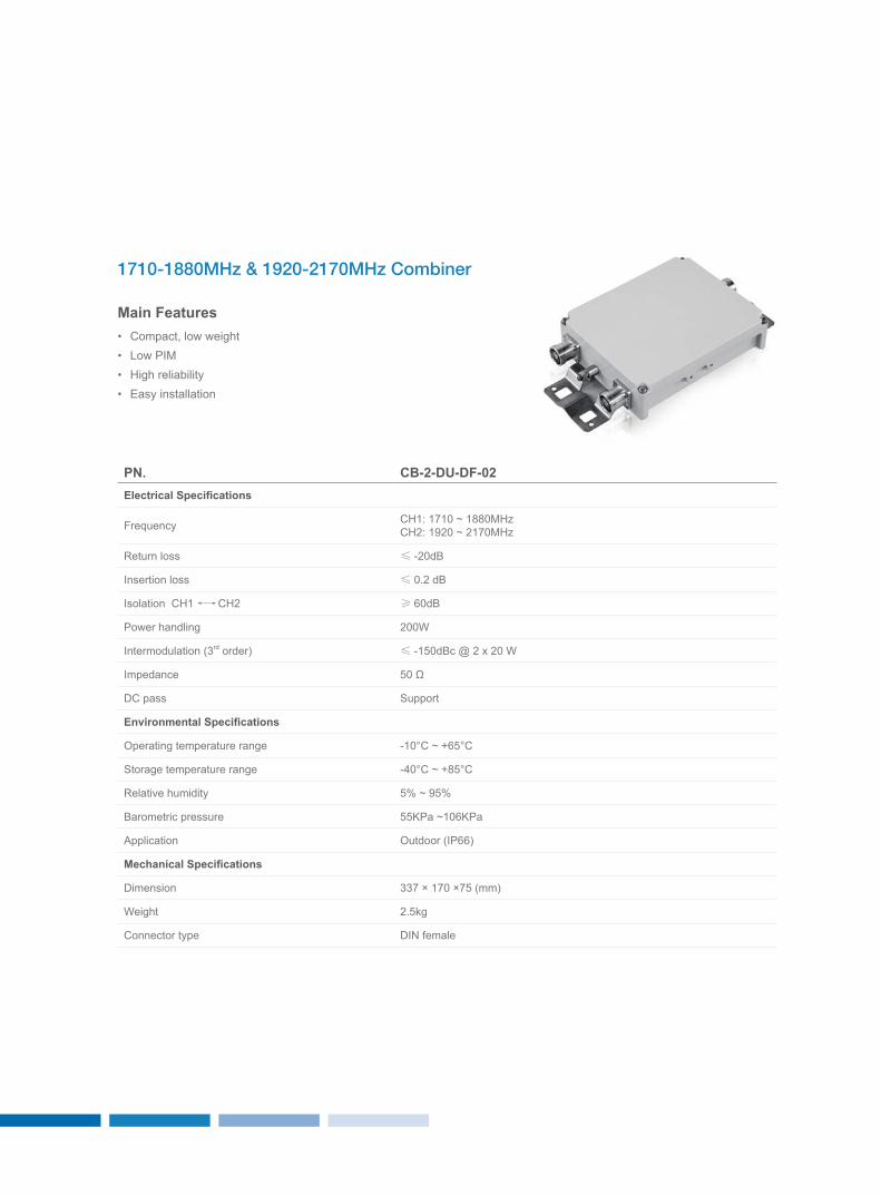
Main Features• Compact, low weight• Low PIM• High reliability• Easy installation
Pn. CB-2-DU-DF-02Electrical Specifications
Frequency CH1: 1710 ~ 1880MHzCH2: 1920 ~ 2170MHz
Return loss ≤ -20dB
Insertion loss ≤ 0.2 dB
Isolation CH1 ←→ CH2 ≥ 60dB
Power handling 200W
Intermodulation (3rd order) ≤ -150dBc @ 2 x 20 W
Impedance 50 Ω
DC pass Support
Environmental Specifications
Operating temperature range -10°C ~ +65°C
Storage temperature range -40°C ~ +85°C
Relative humidity 5% ~ 95%
Barometric pressure 55KPa ~106KPa
Application Outdoor (IP66)
Mechanical Specifications
Dimension 337 × 170 ×75 (mm)
Weight 2.5kg
Connector type DIN female
1710-1880MHz & 1920-2170MHz Combiner
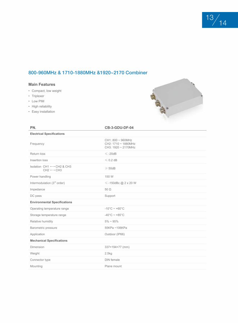
Main Features• Compact, low weight• Triplexer• Low PIM• High reliability• Easy installation
Pn. CB-3-GDU-DF-04Electrical Specifications
FrequencyCH1: 800 ~ 960MHzCH2: 1710 ~ 1880MHzCH3: 1920 ~ 2170MHz
Return loss ≤ -20dB
Insertion loss ≤ 0.2 dB
Isolation CH1 ←→ CH2 & CH3 CH2 ←→ CH3 ≥ 50dB
Power handling 150 W
Intermodulation (3rd order) ≤ -150dBc @ 2 x 20 W
Impedance 50 Ω
DC pass Support
Environmental Specifications
Operating temperature range -10°C ~ +60°C
Storage temperature range -40°C ~ +85°C
Relative humidity 5% ~ 95%
Barometric pressure 55KPa ~106KPa
Application Outdoor (IP66)
Mechanical Specifications
Dimension 337×194×77 (mm)
Weight 2.5kg
Connector type DIN female
Mounting Plane mount
800-960MHz & 1710-1880MHz &1920~2170 Combiner
1413

LTE Combiner
Pn. CB-2-CMLTe-nF-01Electrical Specifications
Frequency (MHz)GSM&DCS TD-SDCMA&TD-LTE
885~954 1710~1830 1880~2025 2320~2370
Return loss ≤ -17.7dB
Insertion loss ≤ 0.6dB
Ripple ≤ 0.4dB
Isolation ≥ 80dB
Intermodulation ≤ -140@2x20W
Power handling 50 Ω
Operating temperature -40°C ~ +85°C
Mechanical Specifications
Application Indoor
Connector type N female
Pn. CB-2-CMLTe-nF-02Electrical Specifications
Frequency (MHz)TD-SDCMA TD-LTE
1880~2025 2320~2370
Return loss ≤ -17.7dB
Insertion loss ≤ 0.6dB
Ripple ≤ 0.4dB
Isolation ≥ 80dB
Intermodulation ≤ -140@2x20W
Power handling 50 Ω
Operating temperature -40°C ~ +85°C
Mechanical Specifications
Application Indoor
Connector type N female
customized combiner
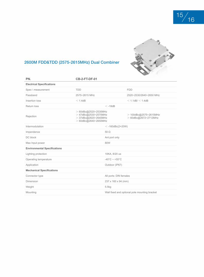
2600M FDD&TDD (2575-2615MHz) Dual Combiner
Pn. CB-2-FT-DF-01Electrical Specifications
Spec \ measurement TDD FDD
Passband 2575~2615 MHz 2520~2530/2640~2650 MHz
Insertion loss < 1.4dB < 1.1dB/ < 1.4dB
Return loss < -18dB
Rejection
> 60dBc@2520~2530MHz> 47dBc@2530~2570MHz> 37dBc@2620~2640MHz> 60dBc@2640~2650MHz
> 100dBc@2575~2615MHz> 60dBc@2672~2712MHz
Intermodulation < -160dBc(2×20W)
Impendence 50 Ω
DC block Ant port only
Max Input power 80W
Environmental Specifications
Lighting protection 10KA, 8/20 us
Operating temperature -40°C ~ +55°C
Application Outdoor (IP67)
Mechanical Specifications
Connector type All ports: DIN females
Dimension 237 x 160 x 94 (mm)
Weight 5.5kg
Mounting Wall fixed and optional pole mounting bracket
1615
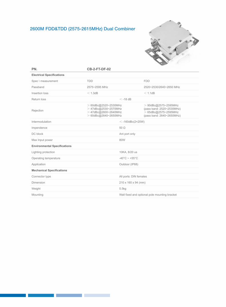
2600M FDD&TDD (2575-2615MHz) Dual Combiner
Pn. CB-2-FT-DF-02Electrical Specifications
Spec \ measurement TDD FDD
Passband 2575~2595 MHz 2520~2530/2640~2650 MHz
Insertion loss < 1.3dB < 1.1dB
Return loss < -18 dB
Rejection
> 60dBc@2520~2530MHz> 47dBc@2530~2570MHz> 47dBc@2600~2640MHz> 60dBc@2640~2650MHz
> 90dBc@2575~2595MHz(pass band: 2520~2530MHz)> 65dBc@2575~2595MHz(pass band: 2640~2650MHz)
Intermodulation < -160dBc(2×20W)
Impendence 50 Ω
DC block Ant port only
Max Input power 80W
Environmental Specifications
Lighting protection 10KA, 8/20 us
Operating temperature -40°C ~ +55°C
Application Outdoor (IP68)
Mechanical Specifications
Connector type All ports: DIN females
Dimension 210 x 160 x 94 (mm)
Weight 5.5kg
Mounting Wall fixed and optional pole mounting bracket
GSM DCS TD Combiner
Pn. CB-2-GDT-nF-01Electrical Specifications
Frequency P1: 885~954 MHz (GSM)&1710~1880 MHz (DCS) P2:1920~2170 MHz (TD)
Return loss ≤ -17.7dB
Insertion loss ≤ 0.8dB
Ripple ≤ 0.6dB
Isolation ≥ 80dB@885~954/1710~1880 MHz≥ 80dB@1920~2170 MHz
≥ 80dB@885~954 MHz≥ 80dB@1710~1880 MHz
Power handling 200W
Intermodulation (3rd order) ≤ -130dBc(2x20W)
Pn. CB-2-GDTTT-nF-01Electrical Specifications
Frequency
P1: 889~909&934~954 MHz (GSM)&1710~1735&1805~1830 MHz (DCS)&1880~1920 MHz (TD-F)&2010~2025 MHz (TD-A)
P2: 2320~2370 MHz(TD-E)
Return loss ≤ -17.7dB
Insertion loss ≤ 0.8dB
Ripple ≤ 0.6dB
Isolation ≥ 82dB@889~909&934~954/1710~1735&1805~1830/2320~2370MHz≥ 31dB@2320~2370MHz
≥ 31dB@1880~1920/2010~2025MHz
Power handling 250W
Intermodulation (3rd order) ≤ 120dBc(2x20W)
Pn. CB-3-GDTTT-nF-01Electrical Specifications
Frequency P1: 2300~2400MHz (TD-E) P2: 1880~1920 MHz(TD-F) &2010~2025MHz (TD-A)
P3:885~954 MHz (GSM)&1710~1830MHz(DCS)
Return loss ≤ 17 dB
Insertion loss ≤ 0.8dB
Ripple ≤ 0.6dB
Isolation
≥ 80dB@885~954MHz≥ 80dB@1710~1830MHz≥ 80dB@1880~1920MHz≥ 80dB@2010~2025MHz
≥ 80dB@885~954MHz≥ 80dB@1710~1830MHz≥ 80dB@2300~2400MHz
≥ 80dB@1880~1920MHz≥ 80dB@2010~2025MHz≥ 80dB@2300~2400MHz
Power handling 160W
Intermodulation(3rd order) ≤ -150dBc(2x20W)
Impedance 50Ω
Mechanical Specificationss
Operating temperature -25°C ~ +65°C
Connector type N female
1817

GSM DCS UMTS2100&WLAN Combiner
GSM DCS UMTS&WLAN Band Combiner
Pn. CB-2-GDUTW-nF-01Electrical Specifications
FrequencyP1: 2G&TD 800~960 MHz&1710~2170 MHz&2300~2380 MHz
P2: WLAN2400~2500MHz(WLAN)
Return loss ≤ 17dB
Insertion loss ≤ 0.5dB ≤ 1.2dB ( Limit temperature≤1.3dB )
Ripple ≤ 0.4dB ≤ 0.9dB
Isolation ≥ 80dB@2400~2500MHz ≥ 80dB@800~2380MHz
Power handling 160W
Intermodulation (3rd order) ≤ -150dBc(2x43dBm)
Impedance 50Ω
Environmental Specifications
Operating temperature range -25°C ~ +65°C
Application Outdoor(IP65)
Mechanical Specifications
Connector type N female
Pn. CB-4-GDWL-nF-03Electrical Specifications
Frequency 885~954MHz 1710~1880MHz 1920~2170MHz 2400~2500 MHz
Insertion loss ≤ 0.3dB ≤ 0.7dB ≤ 0.7dB ≤ 0.8dB
Return loss, all ports ≤ 20dB
Rejection 80dBc@Other Bands
Continuous average power 100W max
Intermodulation (3rd order) ≤ -140dBc @2 x 20 W
Impedance 50Ω
Environmental Specifications
Operating temperature range -25°C ~ +65°C
Application Indoor
Mechanical Specifications
Dimension 200 x 160 x 64 (mm)
Weight 3.5kg
Connector type N female

FIltErS
• Suitable for indoor or outdoor applications• Available as a single unit, or for Xpol antennas as a double unit• Wall or mast mounting• Low insertion loss• DC stop available as an accessory• Dielectric technology to achieve high rejection in narrow bandwidth
2019
PASSIve CoMPonenTS
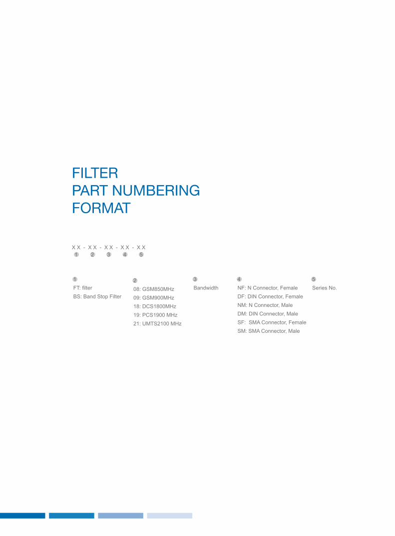
FIltEr PArt nuMbErIng ForMAt
1FT: filterBS: Band Stop Filter
208: GSM850MHz 09: GSM900MHz 18: DCS1800MHz 19: PCS1900 MHz21: UMTS2100 MHz
3Bandwidth
4NF: N Connector, Female DF: DIN Connector, Female NM: N Connector, Male DM: DIN Connector, Male SF: SMA Connector, Female SM: SMA Connector, Male
5Series No.
1 2 3 4 5X X - X X - X X - X X - X X

Main Features• High selective• Lighting protection• High reliability• Easy installation
UMTS1900 Notch Filter
Pn. BS-19-20-DF-01Electrical Specifications
Frequency Passband: 1905~1910MHz&1985~1990MHzStopband: 1960~1980MHz
Pass band insertion ≤ 0.8dB
Pass band return loss ≤ -18dB
Stop band rejection ≥ 50dBc
Power handling 80W
Impedance 50 Ω
Lighting protection 10KA, 8/20 us
Environmental Specifications
Operating temperature range -40°C~+55°C
Relative humidity 5% ~ 95%
Application Outdoor(IP67)
Mechanical Specifications
Connector type 7/16 DIN female
Dimension 188×134×63 (mm)
Weight 3.5kg
Mounting Wall fixed and optional pole mounting bracket
notch Filter
2221
Main Features• Compact, low weight• High reliability• Easy installation
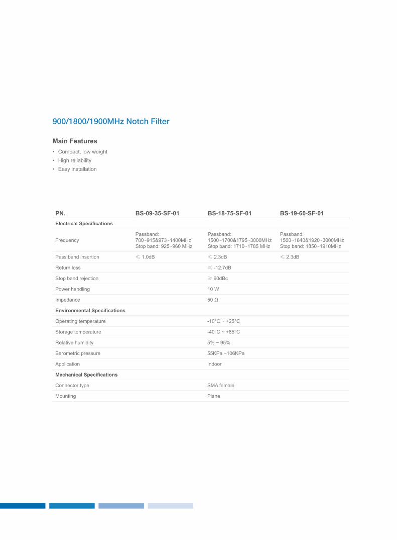
900/1800/1900MHz Notch Filter
Pn. BS-09-35-SF-01 BS-18-75-SF-01 BS-19-60-SF-01Electrical Specifications
FrequencyPassband: 700~915&973~1400MHz Stop band: 925~960 MHz
Passband: 1500~1700&1795~3000MHzStop band: 1710~1785 MHz
Passband: 1500~1840&1920~3000MHzStop band: 1850~1910MHz
Pass band insertion ≤ 1.0dB ≤ 2.3dB ≤ 2.3dB
Return loss ≤ -12.7dB
Stop band rejection ≥ 60dBc
Power handling 10 W
Impedance 50 Ω
Environmental Specifications
Operating temperature -10°C ~ +25°C
Storage temperature -40°C ~ +85°C
Relative humidity 5% ~ 95%
Barometric pressure 55KPa ~106KPa
Application Indoor
Mechanical Specifications
Connector type SMA female
Mounting Plane
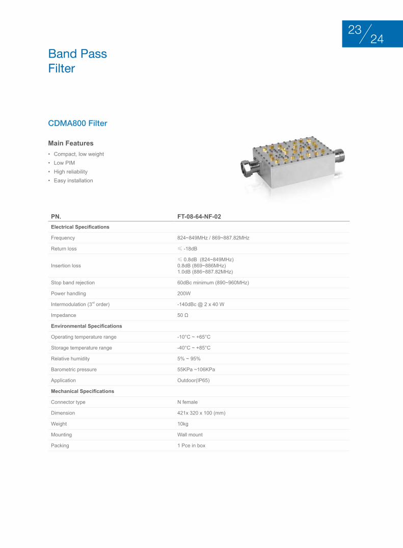
Main Features• Compact, low weight• Low PIM• High reliability• Easy installation
CDMA800 Filter
Pn. FT-08-64-nF-02Electrical Specifications
Frequency 824~849MHz / 869~887.82MHz
Return loss ≤ -18dB
Insertion loss≤ 0.8dB (824~849MHz)0.8dB (869~886MHz)1.0dB (886~887.82MHz)
Stop band rejection 60dBc minimum (890~960MHz)
Power handling 200W
Intermodulation (3rd order) -140dBc @ 2 x 40 W
Impedance 50 Ω
Environmental Specifications
Operating temperature range -10°C ~ +65°C
Storage temperature range -40°C ~ +85°C
Relative humidity 5% ~ 95%
Barometric pressure 55KPa ~106KPa
Application Outdoor(IP65)
Mechanical Specifications
Connector type N female
Dimension 421x 320 x 100 (mm)
Weight 10kg
Mounting Wall mount
Packing 1 Pce in box
band Pass Filter
2423

Pn. FT-09-75-DF-02Electrical Specifications
Frequency 885~915/930~960 MHz
Return loss ≤ -19dB
Insertion loss ≤ 1.5 dB
Ripple ≤ 1.3 dB
Rejection 70dBc@DC~880 MHz
Power handling 100 W
Intermodulation (3rd order) (5rd order) (7rd order)
≤ -140dBc @ 2 x 20 W≤ -155dBc @ 2 x 20 W≤ -165dBc @ 2 x 20 W
Impedance 50 Ω
Environmental Specifications
Operating temperature range 0°C ~ +65°C
Storage temperature range -40°C ~ +85°C
Relative humidity 5% ~ 95%
Barometric pressure 55 KPa ~106KPa
Application Indoor
Mechanical Specifications
Connector type DIN female
Mounting Plane mount
Main Features• High isolation, low VSWR and loss• High power performance• Compact• Low PIM• High reliability
GSM Filter
General Filter
Pn.
FT-07-10-DF-01LTe 700M external Filter
FT-08-50-DF-01800M CDMA Filter
Electrical Specifications
Frequency 791~801MHz (downlink)832~842MHz (uplink)
824~874.5MHz
Return loss ≤ -18dB
Insertion loss ≤ 1.0dB(downlink)≤ 0.5dB (uplink) ≤ 2.3dB
Rejection > 10dBc(470~790MHz) ≥ 20dBc@700~800MHz≥ 70dBc@880~1000MHz
Power handling 100W
Impedance 50 Ω
Intermodulation (3rd order) ≤ -160dBc @ 2 x 20 W ≤ -150dBc @ 2 x 20 W
Environmental Specifications
Operating temperature -35°C ~ +65°C -25°C ~ +70°C
Applications Outdoor(IP67)
Mechanical Specifications
Connector type DIN female
Dimension 245x 170 x 73 (mm) 250x150x70 (mm)
Weight 2.5kg 3.5Kg
Mounting Wall mount Wall fixed and optional pole mounting bracket
Pn.
FT-09-53-D-01GSM Filter
FT-18-75-nF-01DCS Filter
Electrical Specifications
Frequency 907.5~915/952.5~960 MHz 1805~1880MHz
Return loss ≤ -18dB ≤ -20dB
Insertion loss ≤ 1.0 dB (907.5~915 MHz)≤ 0.6dB (952.5~960 MHz) ≤ 0.5dB
Rejection≥ 65dBc@887~889.5 MHz≥ 80dBc@880~885 MHz≥ 90dBc @871~874 MHz
≥ 45dBc@ 1710~1785MHz≥ 80dBc @ 1920~2500MHz
Power handling 200 W 500W
Impedance 50 Ω
Intermodulation (3rd order) ≤ -150dBc @ 2 x 20 W ≤ -140dBc @ 2 x 20 W
Environmental Specifications
Operating temperature 0°C ~ +65°C -20°C ~ +65°C
Application Indoor Outdoor(IP65)
Mechanical Specifications
Connector type DIN female to DIN male N female
Dimension 142x106x53.3 (mm) 177x150x53 (mm)
Weight 2kg 3.5Kg
Mounting Plane mount
2625

Pn.
FT-19-10-DF-011900M DR Filter
FT-21-100-DF-011940~1950&2130~2140MHz Filter
Electrical Specifications
Frequency 1961.5~1970MHz 1940~1950MHz / 2130~2140MHz
Return loss ≤ -20.8dB ≤ -18dB
Insertion loss ≤ 1.3dB ≤ 0.9dB@1940~1950MHz≤ 0.4dB@2130~2140MHz
Rejection ≥ [email protected] ≥ 45dBc@1962~1970MHz
Power handling 80W 100W
Impedance 50 Ω
Intermodulation (3rd order) ≤ -150dBc @ 2 x 20 W ≤ -140dBc @ 2 x 20 W
Environmental Specifications
Operating temperature -10°C ~ +65°C
Application Outdoor(IP67)
Mechanical Specifications
Connector type DIN female
Dimension 250 x 130 x 65 (mm)
Weight 2kg
Mounting Wall and pole mount
Pn.
FT-26-05-nF-012660~2665MHz High Rejection Filter
FT-33-100-nF-01Wimax Filter
Electrical Specifications
Frequency 2660 ~ 2665 MHz 3300 ~ 3400MHz
Return loss ≤ -18dB ≤ -19dB
Insertion loss ≤ 1.75dB ≤ 0.3dB
Rejection > [email protected]~2675M > 60dBc @3700~4000MHz
Power handling 200 W 10W
Impedance 50 Ω
Intermodulation (3rd order) ≤ -150dBc @ 2 x 20 W
Environmental Specifications
Operating temperature -10°C ~ +65°C
Application Outdoor(IP68) Outdoor(IP67)
Mechanical Specifications
Connector type N female
Dimension 100 x 100 x 49 (mm) 82 x 82 x 35 (mm)
Weight 2kg 0.4kg
Mounting Wall fixed and optional pole mounting bracket Plane mount

duPlExErS
• High isolation, low VSWR and insertion loss, to ensure that the uplink and downlink signal will be not affect each other when through their own.
• High reliability. Specified temperature and humidity range, the electrical performance can be guaranteed in the vibration conditions.
• Easy installation
2827
PASSIve CoMPonenTS

1 2 3 4 5
duPlExEr PArt nuMbErIng ForMAt
1 Dx: DuplexerDDx: Dual Duplexer
208: CDMA800MHz 09: GSM900MHz 18: DCS1800MHz 19: PCS1900MHz21: UMTS2100MHz24: WiFi
3Band Width
4NF: N Connector, Female DF: DIN Connector, Female NM: N Connector, Male DM: DIN Connector, Male SF: SMA Connector, Female SM: SMA Connector, Male
5Series No.
X X - X X - X X - X X - X X
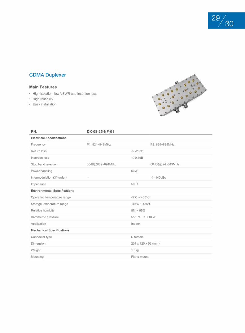
Main Features• High isolation, low VSWR and insertion loss• High reliability• Easy installation
CDMA Duplexer
Pn. DX-08-25-nF-01Electrical Specifications
Frequency P1: 824~849MHz P2: 869~894MHz
Return loss ≤ -20dB
Insertion loss ≤ 0.4dB
Stop band rejection 60dB@869~894MHz 60dB@824~849MHz
Power handling 50W
Intermodulation (3rd order) -- ≤ -140dBc
Impedance 50 Ω
Environmental Specifications
Operating temperature range -5°C ~ +60°C
Storage temperature range -40°C ~ +85°C
Relative humidity 5% ~ 95%
Barometric pressure 55KPa ~ 106KPa
Application Indoor
Mechanical Specifications
Connector type N female
Dimension 201 x 125 x 52 (mm)
Weight 1.5kg
Mounting Plane mount
3029
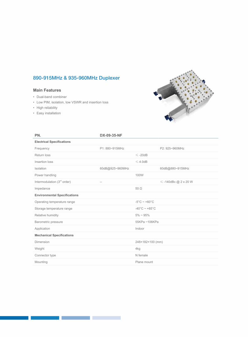
Pn. DX-09-35-nFElectrical Specifications
Frequency P1: 880~915MHz P2: 925~960MHz
Return loss ≤ -20dB
Insertion loss ≤ 4.0dB
Isolation 60dB@925~960MHz 60dB@880~915MHz
Power handling 100W
Intermodulation (3rd order) -- ≤ -140dBc @ 2 x 20 W
Impedance 50 Ω
Environmental Specifications
Operating temperature range -5°C ~ +60°C
Storage temperature range -40°C ~ +85°C
Relative humidity 5% ~ 95%
Barometric pressure 55KPa ~106KPa
Application Indoor
Mechanical Specifications
Dimension 248×182×100 (mm)
Weight 4kg
Connector type N female
Mounting Plane mount
Main Features• Dual-band combiner• Low PIM, isolation, low VSWR and insertion loss• High reliability• Easy installation
890-915MHz & 935-960MHz Duplexer
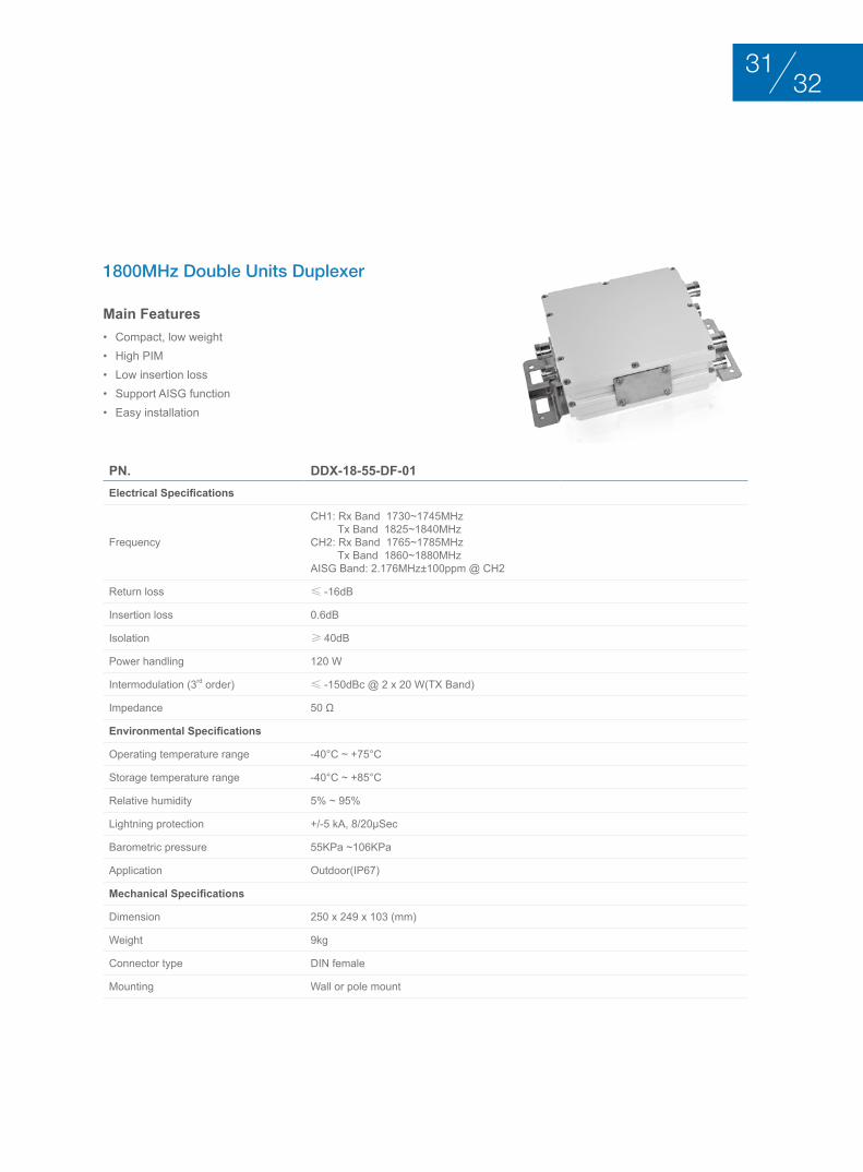
Main Features• Compact, low weight• High PIM• Low insertion loss • Support AISG function• Easy installation
1800MHz Double Units Duplexer
Pn. DDX-18-55-DF-01Electrical Specifications
Frequency
CH1: Rx Band 1730~1745MHz Tx Band 1825~1840MHzCH2: Rx Band 1765~1785MHz Tx Band 1860~1880MHzAISG Band: 2.176MHz±100ppm @ CH2
Return loss ≤ -16dB
Insertion loss 0.6dB
Isolation ≥ 40dB
Power handling 120 W
Intermodulation (3rd order) ≤ -150dBc @ 2 x 20 W(Tx Band)
Impedance 50 Ω
Environmental Specifications
Operating temperature range -40°C ~ +75°C
Storage temperature range -40°C ~ +85°C
Relative humidity 5% ~ 95%
Lightning protection +/-5 kA, 8/20μSec
Barometric pressure 55KPa ~106KPa
Application Outdoor(IP67)
Mechanical Specifications
Dimension 250 x 249 x 103 (mm)
Weight 9kg
Connector type DIN female
Mounting Wall or pole mount
3231

couPlErS
• Covering from 5dB to 40dB• Modular architecture for design flexibility• Enhanced feature for easy installation and maintenance• High performance and reliability • Compact size for minimized environmental and visual impact
PASSIve CoMPonenTS

couPlEr PArt nuMbErIng ForMAt
1 2 3 4 5
1 DC: Cavity Directional Coupler
25: 5 dB 6: 6dB 7: 7dB 8: 8dB 10: 10dB12: 12dB 13: 13dB 15: 15dB 20: 20dB 25: 25dB30: 30dB40: 40dB
34F: 1710~2500 MHz 5F: 800~2200 MHz 6F: 800~2500MHz7F: 800~2700MHz8F: 350~2700MHzAF: 800~960 MHzBF: 1710~2170 MHz CF: 700~960 MHz DF: 300~500 MHz EF:120~240 MHzFF: 300~900MHz
4NF: N Connector, Female DF: DIN Connector, Female NM: N Connector, Male DM: DIN Connector, Male SF: SMA Connector, Female SM: SMA Connector, Male
5Void
X X - X X - X X - X X - X X
3433
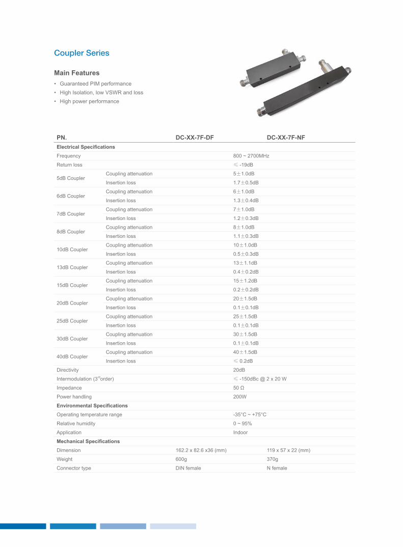
Pn. DC-XX-7F-DF DC-XX-7F-nFElectrical Specifications
Frequency 800 ~ 2700MHz
Return loss ≤ -19dB
5dB CouplerCoupling attenuation 5±1.0dB
Insertion loss 1.7±0.5dB
6dB CouplerCoupling attenuation 6±1.0dB
Insertion loss 1.3±0.4dB
7dB CouplerCoupling attenuation 7±1.0dB
Insertion loss 1.2±0.3dB
8dB CouplerCoupling attenuation 8±1.0dB
Insertion loss 1.1±0.3dB
10dB CouplerCoupling attenuation 10±1.0dB
Insertion loss 0.5±0.3dB
13dB CouplerCoupling attenuation 13±1.1dB
Insertion loss 0.4±0.2dB
15dB CouplerCoupling attenuation 15±1.2dB
Insertion loss 0.2±0.2dB
20dB CouplerCoupling attenuation 20±1.5dB
Insertion loss 0.1±0.1dB
25dB CouplerCoupling attenuation 25±1.5dB
Insertion loss 0.1±0.1dB
30dB CouplerCoupling attenuation 30±1.5dB
Insertion loss 0.1±0.1dB
40dB CouplerCoupling attenuation 40±1.5dB
Insertion loss ≤ 0.2dB
Directivity 20dB
Intermodulation (3rdorder) ≤ -150dBc @ 2 x 20 W
Impedance 50 Ω
Power handling 200W
Environmental Specifications
Operating temperature range -35°C ~ +75°C
Relative humidity 0 ~ 95%
Application Indoor
Mechanical Specifications
Dimension 162.2 x 82.6 x36 (mm) 119 x 57 x 22 (mm)
Weight 600g 370g
Connector type DIN female N female
Main Features• Guaranteed PIM performance• High Isolation, low VSWR and loss• High power performance
Coupler Series

SPlIttErS
• 2, 3, 4 way available• Design breakthroughs for best-in-class performance and value• Broad frequency covering from 350 ~ 3800MHz• Excellent performance
3635
PASSIve CoMPonenTS
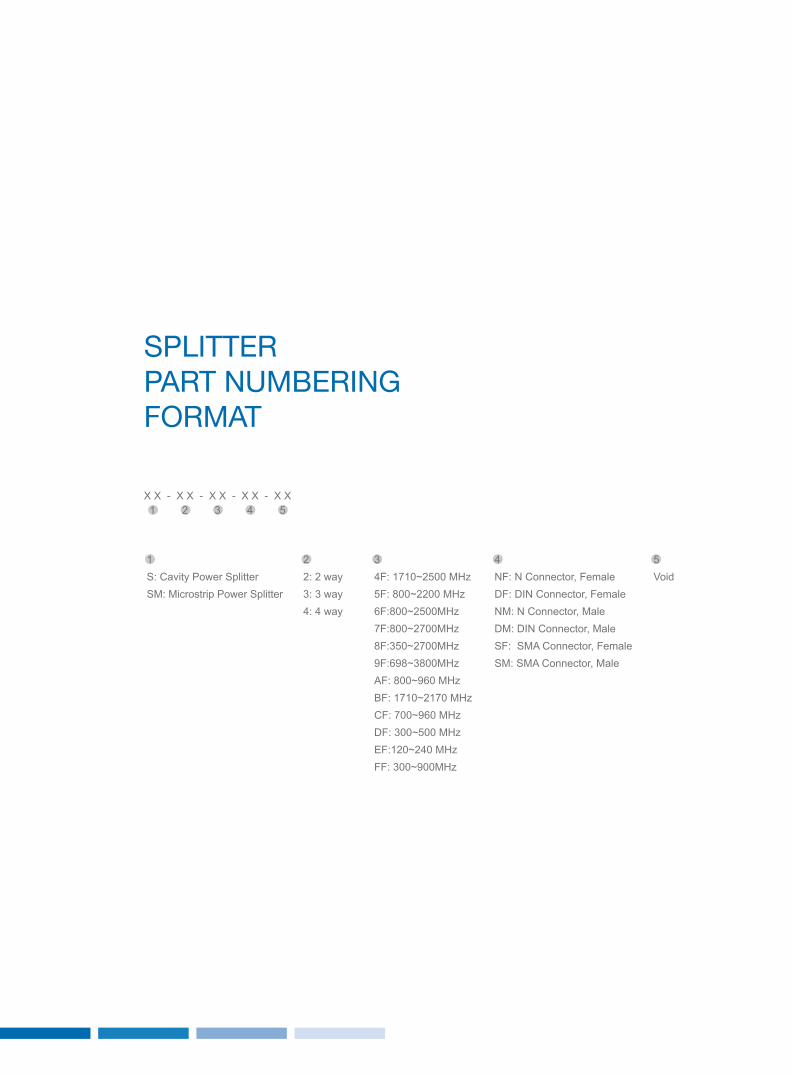
SPlIttEr PArt nuMbErIng ForMAt
1 2 3 4 5
1 S: Cavity Power SplitterSM: Microstrip Power Splitter
22: 2 way 3: 3 way 4: 4 way
34F: 1710~2500 MHz 5F: 800~2200 MHz 6F:800~2500MHz7F:800~2700MHz8F:350~2700MHz9F:698~3800MHzAF: 800~960 MHz BF: 1710~2170 MHz CF: 700~960 MHz DF: 300~500 MHz EF:120~240 MHzFF: 300~900MHz
4NF: N Connector, Female DF: DIN Connector, Female NM: N Connector, Male DM: DIN Connector, Male SF: SMA Connector, Female SM: SMA Connector, Male
5Void
X X - X X - X X - X X - X X
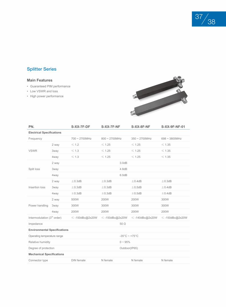
Main Features• Guaranteed PIM performance • Low VSWR and loss • High power performance
Splitter Series
Pn. S-XX-7F-DF S-XX-7F-nF S-XX-8F-nF S-XX-9F-nF-01Electrical Specifications
Frequency 700 ~ 2700MHz 800 ~ 2700MHz 350 ~ 2700MHz 698 ~ 3800MHz
VSWR
2 way ≤ 1.2 ≤ 1.25 ≤ 1.25 ≤ 1.35
3way ≤ 1.3 ≤ 1.25 ≤ 1.25 ≤ 1.35
4way ≤ 1.3 ≤ 1.25 ≤ 1.25 ≤ 1.35
Split loss
2 way 3.0dB
3way 4.8dB
4way 6.0dB
Insertion loss
2 way ±0.3dB ±0.3dB ±0.4dB ±0.3dB
3way ±0.3dB ±0.3dB ±0.5dB ±0.4dB
4way ±0.3dB ±0.3dB ±0.5dB ±0.4dB
Power handling
2 way 500W 200W 200W 300W
3way 300W 300W 300W 300W
4way 200W 200W 200W 200W
Intermodulation (3rd order) ≤ -150dBc@2x20W ≤ -150dBc@2x20W ≤ -140dBc@2x20W ≤ -150dBc@2x20W
Impedance 50 Ω
Environmental Specifications
Operating temperature range -35°C ~ +75°C
Relative humidity 0 ~ 95%
Degree of protection Outdoor(IP65)
Mechanical Specifications
Connector type DIN female N female N female N female
3837

AttEnuAtorS
• Wide frequency band• Power handling ratings from 5 - 200 watt• Low VSWR• Flatness attenuation value• Excellent capacity in anti-pulse and anti-burnout• Rugged aluminum housing for long lasting, reliable performance
PASSIve CoMPonenTS

AttEnuAtor PArt nuMbErIng ForMAt
1 2 3 4 5
1 A: Coaxial Fixed Attenuator
23: 3 dB 5: 5 dB 6: 6 dB 10: 10 dB 15: 15 dB 20: 20 dB 30: 30 dB xx: xx dB
32: 2w limit power 5: 5w limit power 10: 10 w limit power20: 20 w limit power 30: 30 w limit power50: 50 w limit powerxx: xx w limit power
4N: N male to N femaleD: DIN male to DIN female
5Void
X X - X X - X X - X X - X X
4039

Attenuator Series
Pn.Electrical Specifications
Frequency Range(GHz)
Attenuation value & accuracy(dB) MaxVSWR
Powerhandling1-9 10 20 30 40
A-XX-2-n/ A-XX-5-n DC-3 ±0.4 ±0.5 ±0.5 ±0.6 ±0.6 1.20 2W/5W
A-XX-2-n-01/A-XX-5-n-01 DC-4 ±0.4 ±0.5 ±0.5 ±0.7 ±0.7 1.25 2W/5W
A-XX-10-n/A-XX-25-n DC-3 ±0.4 ±0.5 ±0.6 ±0.6 ±1.0 1.20 10W/25W
A-XX-10-n-01/A-XX-25-n-01 DC-4 ±0.5 ±0.6 ±0.75 ±0.75 ±1.0 1.25 10W/25W
A-XX-50-D/A-XX-50-n DC-3 ±0.6 ±0.6 ±0.6 ±0.75 ±1.0 1.20 50W
A-XX-50-D-01/A-XX-50-n-01 DC-4 ±0.75 ±0.75 ±0.75 ±0.75 ±1.0 1.25 50W
A-XX-100-D DC-3 -- ±0.6 ±0.6 ±0.75 ±0.75 1.30 100W
A-XX-100-D-01 DC-4 -- ±0.75 ±0.75 ±0.75 ±0.75 1.35 100W
A-XX-100-n DC-3 -- ±0.5 ±1.0 ±1.2 ±1.5 1.35 100W
A-XX-100-n-01 DC-4 -- ±0.75 ±0.75 ±0.75 ±0.75 1.35 100W
A-XX-150-D DC-3 -- ±1.5 ±1.0 ±0.8 ±0.8 1.30 150W
A-XX-150-n DC-3 -- ±1.5 ±1.0 ±0.8 ±0.8 1.30 150W
A-XX-150-n-01 DC-4 -- ±1.5 ±1.5 ±1.0 ±1.0 1.35 150W
A-XX-200-D/A-XX-200-n DC-3 -- ±1.25 ±1.25 ±0.8 ±0.8 1.35 200W
xx refer to attenuation in dB
Environmental Specifications
Operating temperature -40°C ~ +120°C (A-xx-200-N: -55°C ~ +125°C)
Relative humidity 5% ~ 95%
Application Indoor
Mechanical Specifications
Connector type N male to N female / DIN male to DIN female
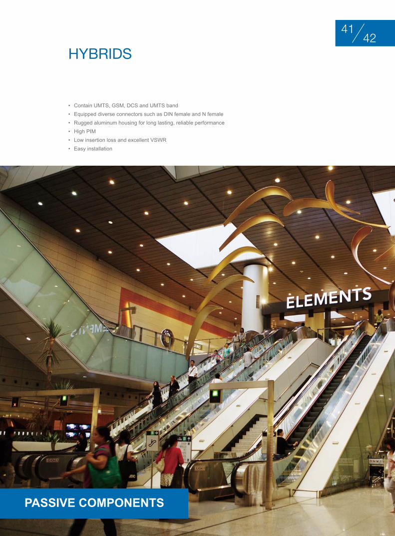
hybrIdS
• Contain UMTS, GSM, DCS and UMTS band • Equipped diverse connectors such as DIN female and N female• Rugged aluminum housing for long lasting, reliable performance• High PIM• Low insertion loss and excellent VSWR • Easy installation
4241
PASSIve CoMPonenTS

hybrId PArt nuMbErIng ForMAt
1 2 3 4 5
1 H: Cavity Hybrid Bridge (3dB Bridge)HM: Microstrip Hybrid Bridge (3dB Bridge)
24F: 1710~2500 MHz 5F: 800~2200 MHz 6F: 800~2500MHz7F: 800~2700MHzAF: 800~960 MHz BF: 1710~2170 MHz CF: 700~960 MHz
3Void (for special requirements)
4NF: N Connector, Female DF: DIN Connector, Female NM: N Connector, Male DM: DIN Connector, Male SF: SMA Connector, Female SM: SMA Connector, Male
5Void
X X - X X - X X - X X - X X
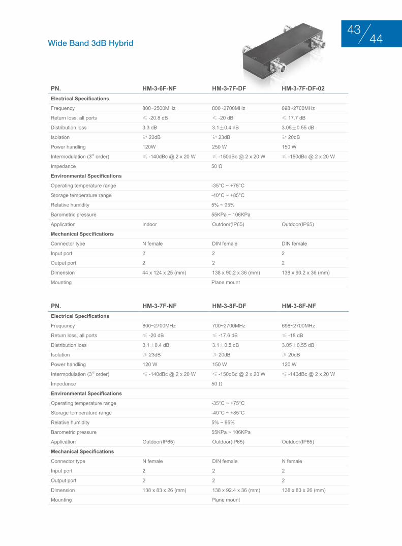
Wide Band 3dB Hybrid
Pn. HM-3-6F-nF HM-3-7F-DF HM-3-7F-DF-02Electrical Specifications
Frequency 800~2500MHz 800~2700MHz 698~2700MHz
Return loss, all ports ≤ -20.8 dB ≤ -20 dB ≤ 17.7 dB
Distribution loss 3.3 dB 3.1±0.4 dB 3.05±0.55 dB
Isolation ≥ 22dB ≥ 23dB ≥ 20dB
Power handling 120W 250 W 150 W
Intermodulation (3rd order) ≤ -140dBc @ 2 x 20 W ≤ -150dBc @ 2 x 20 W ≤ -150dBc @ 2 x 20 W
Impedance 50 Ω
Environmental Specifications
Operating temperature range -35°C ~ +75°C
Storage temperature range -40°C ~ +85°C
Relative humidity 5% ~ 95%
Barometric pressure 55KPa ~ 106KPa
Application Indoor Outdoor(IP65) Outdoor(IP65)
Mechanical Specifications
Connector type N female DIN female DIN female
Input port 2 2 2
Output port 2 2 2
Dimension 44 x 124 x 25 (mm) 138 x 90.2 x 36 (mm) 138 x 90.2 x 36 (mm)
Mounting Plane mount
Pn. HM-3-7F-nF HM-3-8F-DF HM-3-8F-nFElectrical Specifications
Frequency 800~2700MHz 700~2700MHz 698~2700MHz
Return loss, all ports ≤ -20 dB ≤ -17.6 dB ≤ -18 dB
Distribution loss 3.1±0.4 dB 3.1±0.5 dB 3.05±0.55 dB
Isolation ≥ 23dB ≥ 20dB ≥ 20dB
Power handling 120 W 150 W 120 W
Intermodulation (3rd order) ≤ -140dBc @ 2 x 20 W ≤ -150dBc @ 2 x 20 W ≤ -140dBc @ 2 x 20 W
Impedance 50 Ω
Environmental Specifications
Operating temperature range -35°C ~ +75°C
Storage temperature range -40°C ~ +85°C
Relative humidity 5% ~ 95%
Barometric pressure 55KPa ~ 106KPa
Application Outdoor(IP65) Outdoor(IP65) Outdoor(IP65)
Mechanical Specifications
Connector type N female DIN female N female
Input port 2 2 2
Output port 2 2 2
Dimension 138 x 83 x 26 (mm) 138 x 92.4 x 36 (mm) 138 x 83 x 26 (mm)
Mounting Plane mount
4443

Pn. HM-6-6F-nF HM-6-6F-nF-01Electrical Specifications
Frequency 800 ~ 2500MHz
Return loss ≤ -20.8dB
Distribution loss 6.7dB 6.6dB
Isolation 23dB 22dB
Power handling 100W / Input port(Normal pressure and temperature) 50W / input port
Intermodulation (3rd order) ≤ -140dBc @ 2 x 20 W
Impedance 50 Ω
Environmental Specifications
Operating temperature range -25°C ~ +75°C -35°C ~ +75°C
Storage temperature range -40°C ~ +85°C -40°C ~ +85°C
Relative humidity 0% ~ 95% 5% ~ 95%
Barometric pressure 55KPa ~ 106KPa
Application Outdoor(IP65) Indoor
Mechanical Specifications
Dimension 261 x 98 x 26 (mm)
Weight 2.2kg 2.0kg
Connector type N female
Input port 4 4
Output port 4 1
Mounting Plane mount
6dB Hybrid Unit

tErMInAtIon loAdS
• Power handling ratings from 5 - 200 watt• Wide frequency band • Low VSWR • Excellent capacity in anti-pulse and burnout • Easy to be installed
4645
PASSIve CoMPonenTS

tErMInAtIon loAd PArt nuMbErIng ForMAt
1 2 3 4 5
1 L: Termination Load
22: 2 W5: 5 W10: 10 W20: 20 W 30: 30 W50: 50 Wxx: xx W
3Void (for special requirements)
4NF: N Connector, Female DF: DIN Connector, Female NM: N Connector, Male DM: DIN Connector, Male SF: SMA Connector, Female SM: SMA Connector, Male
5Void
X X - X X - X X - X X - X X
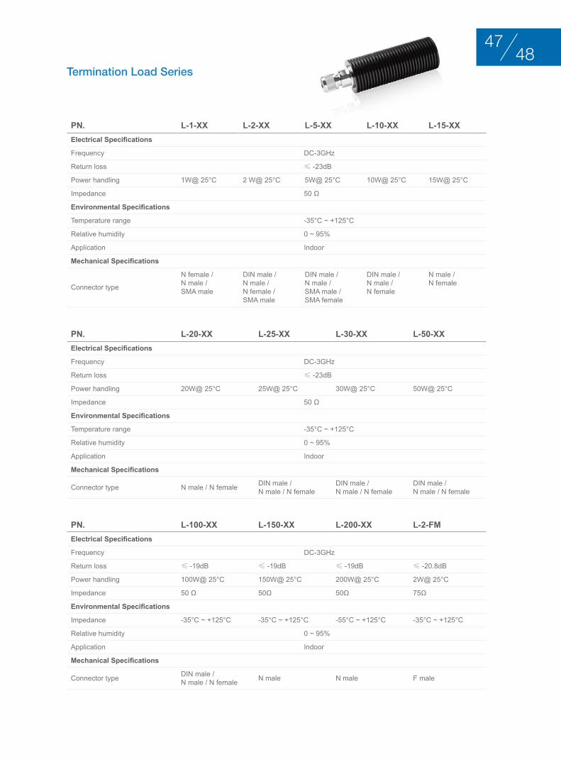
Termination Load Series
Pn. L-1-XX L-2-XX L-5-XX L-10-XX L-15-XXElectrical Specifications
Frequency DC-3GHz
Return loss ≤ -23dB
Power handling 1W@ 25°C 2 W@ 25°C 5W@ 25°C 10W@ 25°C 15W@ 25°C
Impedance 50 Ω
Environmental Specifications
Temperature range -35°C ~ +125°C
Relative humidity 0 ~ 95%
Application Indoor
Mechanical Specifications
Connector type
N female /N male /SMA male
DIN male / N male / N female / SMA male
DIN male / N male / SMA male / SMA female
DIN male / N male / N female
N male / N female
Pn. L-20-XX L-25-XX L-30-XX L-50-XXElectrical Specifications
Frequency DC-3GHz
Return loss ≤ -23dB
Power handling 20W@ 25°C 25W@ 25°C 30W@ 25°C 50W@ 25°C
Impedance 50 Ω
Environmental Specifications
Temperature range -35°C ~ +125°C
Relative humidity 0 ~ 95%
Application Indoor
Mechanical Specifications
Connector type N male / N female DIN male /N male / N female
DIN male / N male / N female
DIN male / N male / N female
Pn. L-100-XX L-150-XX L-200-XX L-2-FMElectrical Specifications
Frequency DC-3GHz
Return loss ≤ -19dB ≤ -19dB ≤ -19dB ≤ -20.8dB
Power handling 100W@ 25°C 150W@ 25°C 200W@ 25°C 2W@ 25°C
Impedance 50 Ω 50Ω 50Ω 75Ω
Environmental Specifications
Impedance -35°C ~ +125°C -35°C ~ +125°C -55°C ~ +125°C -35°C ~ +125°C
Relative humidity 0 ~ 95%
Application Indoor
Mechanical Specifications
Connector type DIN male /N male / N female N male N male F male
4847
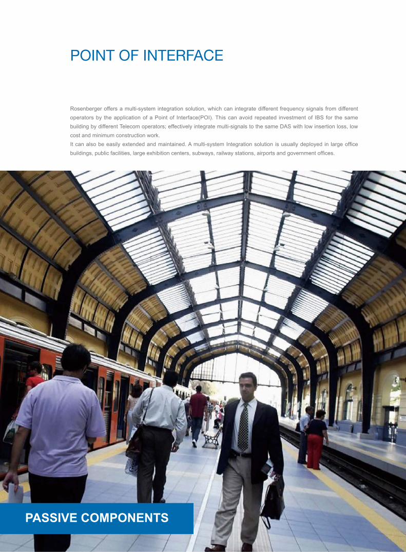
PoInt oF IntErFAcE
Rosenberger offers a multi-system integration solution, which can integrate different frequency signals from different operators by the application of a Point of Interface(POI). This can avoid repeated investment of IBS for the same building by different Telecom operators; effectively integrate multi-signals to the same DAS with low insertion loss, low cost and minimum construction work.It can also be easily extended and maintained. A multi-system Integration solution is usually deployed in large office buildings, public facilities, large exhibition centers, subways, railway stations, airports and government offices.
PASSIve CoMPonenTS
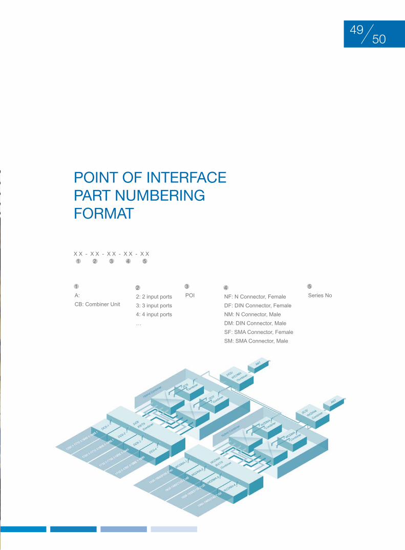
PoInt oF IntErFAcEPArt nuMbErIng ForMAt
1 2 3 4 5
1 A: CB: Combiner Unit
22: 2 input ports3: 3 input ports4: 4 input ports…
3POI
4NF: N Connector, Female DF: DIN Connector, Female NM: N Connector, Male DM: DIN Connector, Male SF: SMA Connector, Female SM: SMA Connector, Male
5Series No
X X - X X - X X - X X - X X
5049

Pn. CB-6-PoI-DF-01Electrical Specifications
Frequency
GSM900: 890~915/935~960 MHzGSM1800-1: 1725~1750/1820~1845 MHzGSM1800-2: 1760~1770/1855~1865MHz3G-1: 1920~1935~2110~2125 MHz3G-2: 1935~1945/2125~2135 MHz3G-3: 1945~1955/2135~2145MHz
Return loss ≤ -18dB for all ports
Insertion loss≤ 1.0dB (GSM900)≤ 3.0dB (GSM1800)≤ 5.5dB (3G)
Isolation Same bands: 40dB minimumDifferent bands: 80dB minimum
Power handling 100 W (3G)200 W (GSM900 & GSM1800)
Intermodulation (3rd order) ≤ -143dBc @ 2 x 20 W
Impedance 50 Ω
Environmental Specifications
Operating temperature range -25°C ~ +60°C
Storage temperature range -40°C ~ +85°C
Relative humidity 5% ~ 85%
Barometric pressure 55KPa ~106KPa
Application Indoor
Mechanical Specifications
Dimension 592 × 402 × 215 (mm)
Weight 30kg
Connector type Din female
BTS port 6
ANT port 1
Monitor port 1 (-30±2 dBc)
Mounting Wall mount
Main Features• Compact, low weight• High Isolation, Low VSWR and Loss• High reliability• Multiple system, including GSM, DCS and UMTS
GSM, DCS & UMTS Band Combiner Unit

Pn. CB-13-PoI-DF-04
Electrical Specifications
Frequency
CDMA 800-1:825~835/870~880 MHzCDMA 800-2: 835~845/880~890 MHzGSM1800-1: 1710~1717.5/1805~1812.5MHzGSM1800-2: 1717.5~1722.5/1812.5~1817.5 MHz or 1750~1765/1845~1860MHzGSM1800-3: 1722.5~1730/1817.5~1825 MHz or 1745~1750/1840~1845 MHz or 1765~1775/1860~1870 MHzGSM1800-4: 1730~1745/1825~1840MHzGSM1800-5: 1775~1785/1870~1880MHzUMTS- 1: 1920~1930/2110~2120MHzUMTS -2: 1930~1935/2120~2125MHzUMTS -3: 1935~1945/2125~2135MHzUMTS -4: 1945~1950/2135~2140MHzUMTS -5: 1950~1960/2140~2150MHzWiFi: 2400~2500MHz
Return loss ≤ -18dB for all ports
Insertion loss ≤ 8.5dB (CDMA800 & WIFi)≤ 9.5dB (DCS & UMTS )
Isolation Same bands: 50dB minimumDifferent bands: 110dB minimum
Power handling 100 W
Intermodulation (3rd order) ≤ -143dBc @ 2 x 20 W
Impedance 50 Ω
Environmental Specifications
Operating temperature range -5°C ~ +60°C
Storage temperature range -40°C ~ +85°C
Relative humidity 5% ~ 85%
Barometric pressure 55KPa ~106KPa
Application Indoor
Mechanical Specifications
Dimension 800 × 600 × 500 (mm)
Weight 95kg
Connector type DIN female
BTS port 13
ANT port 4
Monitor port 4 x 30dBc(SMA female)
Mounting Rack mount
Main Features• Compact, low weight• High Isolation, Low VSWR and Loss• High reliability• Multiple system, including CDMA, DCS, UMTS and WiFi
CDMA, DCS, UMTS & WIFi Band Combiner Unit52
51

roSEnbErgEr SErVIcE
PASSIve CoMPonenTS

5453
Rosenberger offers professional services that improve network design, reliability, scalability and efficiency.
Our service core competences include:• Network optimization• Technical consultation• Customized product design• Installation & commissioning• Onsite training & supervision• System troubleshooting• After-sales services
In addition, we also offer professional training, technical support and workshops for distributors and agents. We are committed to offering exceptional services for our customers.
Rosenberger is much more than just a supplier – Rosenberger is a valued development partner and we will strive to meet new challenges in order to scale to new heights.

PA
SS
IVE
C
OM
PO
NE
NT
SPASSIVE COMPONENTS
Rosenberger Asia Pacific Electronic Co., Ltd.
No.3, Anxiang Street, Block B, Tianzhu Airport Industrial Zone
Beijing, China 101300
Tel : (+86 10) 80481995
Fax : (+86 10) 80497052
Email: [email protected]
Rosenberger (Shanghai) Technology Co.,Ltd.
No. 303, Xinke Road, Qingpu Industrial Zone
Shanghai, China 201707
Tel : (+86 21) 69214567
Fax : (+86 21) 69212923
Rosenberger Asia Pacific Electronic Co., Ltd. Shanghai Division
B7, No. 509, Renqing Road, East Zone of Zhangjiang High-Tech Park
Shanghai, China 201201
Tel : (+86 21) 58995997
Fax : (+86 21) 58995594
Rosenberger Asia Pacific Electronic Co., Ltd. Dongguan Division
3rd Floor, Building E, Pingqian Industrial Park, Dongkeng Town
Dongguan, Guangdong Province, China
Tel : (+86 769) 82802098
Fax : (+86 769) 82802099
Rosenberger All rights reserved. 1st Edition, 2013
Please visit our website: www.RosenbergerAP.com
www.RosenbergerAP.com