pascal series 2033 - 2063 m /h h1 seriespilneyo/hifrost/3he pumping system/2063h.pdf · en asie,...
TRANSCRIPT

PASCAL Series2033 - 2063 m3/h
H1 series
LES POMPES PRIMAIRES à PALETTESROTARY VANE PUMPS
Manuel UtilisateurUser’s Manual
Réal
izat
ion/
Publ
icat
ion:
Alc
atel
Vac
uum
Tec
hnol
ogy
Fran
ce -
Use
r’s M
anua
l - E
d 04
- D
ate
: 12/
2009
- P
art
Num
ber:
065
094 *065094*

FR 0
2834
- E
ditio
n 04
- F
ev 2
008
Avec 45 ans d’expérience, aujourd’hui AVT garantit une présence internationale auprès de ses clients et distributeurs expérimentés. Aux Etats-Unis, Alcatel Vacuum Products (Hingham-MA) fondé il y a trente ans, a été la première étape. Deux autres filiales à Fremont (CA) et Tempe (AZ) renforcent notre présence sur ce territoire. En Europe, la maison mère AVT-France et ses filiales, Alcatel Hochvakuumtechnik (Allemagne), Alcatel Vacuum Technology U.K. (Grande-Bretagne), Alcatel Vacuum Technology Benelux (Pays-Bas), Alcatel Vacuum Systems (Italie), Adixen Sensistor AB en Suède (2007) sont le point d’ancrage de réseaux de partenaires couvrant toute l’Europe.En Asie, notre présence a démarré en 1993 avec Alcatel Vacuum Technology au Japon, puis a été renforcée avec Alcatel Vacuum Technology Korea (1995), Alcatel Vacuum Technology Taiwan (2001), Alcatel Vacuum Technology Singapore, et plus récemment Alcatel Vacuum Technology Shanghai en Chine (2004). Plus de quarante agents viennent compléter cette organisation sur différents continents. Les utilisateurs de nos produits peuvent donc, en toutes circonstances et dans un délai rapide, compter sur nos experts en Technologie du Vide.
Alcatel Vacuum Technology, filiale du groupe Alcatel-Lucent fournit à travers le monde des pompes à vide, des détecteurs de fuites à hélium et hydrogène, des plasma sensors et des composants de mesure. Grâce à une gamme complète de produits, nous sommes présents dans différents domaines comme l’instrumentation, la recherche et développement, l’industrie et le semi conducteur. Alcatel Vacuum Technology, leader international dans le domaine du vide, a créé sa marque de produits Adixen. La compagnie française, certifiée ISO 9001 et 14001, experte dans le support et le service, développe ses produits Adixen d’un haut niveau de qualité en conformité avec les exigences environnementales.

EN – 1
EN
Intr
od
uct
ion
Rotary vane pumps2033 H1 et 2063 H1
Welcome
Dear customer,
You have just bought an Adixen rotary vane pump. We would like to thank you and are proud to count you among our customers.
This product is a result of experience acquired over many years by Alcatel Vacuum Technology in the design of rotary vane pumps.
APPLICATIONS:
• CLOSED LOOP CRYOGENIC SYSTEMS
• CFC RECOVERY
• REACTIVES GASES
.
• PRECIOUS GASES
We suggest that you read this manual, particularly the chapter on installation and operation, before you start to use this pump so that you can obtain optimum levels of performance and complete satisfaction from this equipment.

EN – 2
Copyright/Intellectual property:The use of Adixen products are subject to copyright and intellectual property rights in force in any jurisdiction. All rights reserved. including copying this document in whole or any part without prior written authorization from Alcatel Vacuum Technology France.Specifications and information are subject to change without notice by Alcatel Vacuum Technology France.
This product complies with the requirements of European Directives. listed in the Declaration of Conformity contained in page 55 of this manual. These Directives are amended by Directive 93/68/E.E.C (E.C. Marking).
Indicates a potentially hazardous situation which, if not avoided, could result in moderate or minor injury. It may also be used to alert against unsafe practices.
Indicates a potentially hazardous situation which, if not avoided, could result in property damage.
Indicates an imminently hazardous situation that, if not avoided, will result in death or severe injury (extreme situations).
Indicates a potentially hazardous situation which, if not avoided, could result in death or severe injury.

EN – 3
Contents
The PASCAL series 2033 - 2063 m3/h -H1 SeriesPresentation of the product range ............................................................. 4Operating principle of a rotary vane pump ............................................... 6Oil - Noise liliter - Antisudback ................................................................... 8Technical characteristics ............................................................................. 9Pump dimensions ................................................................................... 12Accessories .............................................................................................. 13
Installation and connectionsSafety instructions ................................................................................... 15Table of recommended oils ...................................................................... 17Filling with oil .......................................................................................... 18Mechanical connections .......................................................................... 20Electrical connections .............................................................................. 22Motor protection ..................................................................................... 23
OperationPrecautions ............................................................................................. 27Operating temperature ........................................................................... 27Before starting up the pump ................................................................... 27Start-up ................................................................................................... 28Particular uses .......................................................................................... 28Oxygen pumping ..................................................................................... 29High pressure pumping and cycling ......................................................... 30
MaintenancePrecautions .............................................................................................. 31Troubleshooting and corrective actions .................................................... 32Maintenance frequency ........................................................................... 35Draining the oil ........................................................................................ 36Flushing the pump ................................................................................... 36Change of type of oil ............................................................................... 37Tools and consumable products ............................................................... 38Disassembling the pump .......................................................................... 40Cleaning components .............................................................................. 42Replacement of all shaft seals .................................................................. 43Reassembling the pump ........................................................................... 44
Safety questionnaire .......................................................................... 47
Declaration of Conformity ................................................................. 49
NomenclatureSpare parts lists ....................................................................................N – 1
Intr
od
uct
ion
Sta
rt-u
pO
pera
tio
nM
ain
ten
an
ceN
om
en
clatu
reEN
P.N.: 065094Ed:04 - December 09

EN – 4
Presentation of the product range
A wide rangeSpecific solutions adapted to
various applications
SD series
Oil seal rotary vane pumps are used in all vacuum technology applications.
They can be used on their own to achieve a maximum vacuum of 10-3 Torr (10-3 mbar). or in pumping assemblies. e.g. at the exhaust of a diffusion pump or turbomolecular pump.
Standard pumps for several purposes (non-corrosive applications).Manufacture of light bulbs. production of TV tubes. manufacture of electronic tubes. metallurgy. centrifuges. etc.
Pumps designed to meet the requirements of analytical instrumentation and R&D.Mass spectrometer. electronic microscopes. GC/MS. LC/MS. gas analyzers. leak detectors. sterilizers. etc.
Pumps suited to the pumping of corrosive gases.R&D. laboratories. freeze-drying. pumping of solvents. etc.
Pumps with increased resistance to meet the requirements of the more aggressive processes of the semiconductor industry.Ion implantation. sputtering. etc.
Sealed pumps offering maximum tightness.Pumping of pure or precious gases.
Nominal flow rate m3/h 30 60
SD Series1 stages 1033SD 1063SD
2 stages 2033SD 2063SD
C1 Series1 stages 1033C1 1063C1
2 stages 2033C1 2063C1
C2 Series 2 stages 2033C2 2063C2
H1 Series 2 stages 2033H1 2063H1
I series
C1 series
C2 series
H1 series

EN – 5
2033 - 2063 m3/h rotary vane pumps. H1 Pascal series
The 33 to 63m3/h pump models, H series are following main characteristics:– A direct drive motor. making
them very compact.– An anti-suckback system
ensures the tightness of the pump during accidental or voluntary shutdowns.
– The universal three-phase phase motor can be disassembled independently of the rest of the pump. without the need to drain the oil case.
– On the oil case and on the central housing 2 sight glasses can be used to inspect the oil level easily when filling the tank and during the operation of the pump.
– A rotary seal near the motor works with two other seals. The two additionnal seals form a sealed compartment immersed in oil. If one of these seals deteriorates, it will become apparent from the change in oil level through the sight glass. The operator can then intervene before the second seal is destroyed.
– The oil casing is made of stainless steel sheet and all welds are checked with the helium leak detector.
– The static O-ring ensure a tightness with respect to the surrounding environment:
• 1.10-7 mbar.l.s-1 when the oilcasing is at a pressure belowatmospheric pressure,• 2.10-6 mbar.l.s-1 when the oilcasing is at overpressure.
The inlet and exhaust end fittings are PNEUROP ISO-KF standardized.They are fitted vertically on the pump at delivery but can be positioned on the horizontal openings if required by operating conditions.They can also be used to connect many of our accessories (see page 13).
The main remplacement parts are interchangeable: This enables easier disassembly-assembly operations and replacement without changing the pump’s performance.
Various accessories can be used to adapt the pump to meet the requirements of your application.
The moulded aluminium pump frame supports the pumping module and the motor. All the parts of the pumping module in contact with gases are free of zinc. copper and cadmium.The other construction materials include cast iron. aluminium alloy. stainless steel. fluorocarbons (FPM). nitril (NBR) and chemically resistant polymers.
1. Oil case2. Base3. Frame4. Electric motor5. Lifting rings6. Inlet end fitting7. Sealed housing filling plug
8. Sealed housing draining plug9. Sealed housing oil level sight glass10. Oil case filling plug11. Exhaust end fitting12 Oil case level sight glass13 Water fittings14 Oil case draining plug
11
94
5
2
3
1
10
14
12
13
6 7 8
EN
Intr
od
uct
ion

EN – 6
Operating principle of the rotary vane pump
The pumping cycle isgiven below:
Inlet
Transfer
Compression
Exhaust
Applications
This is a volumetric pump. with a functional part composed of:– A hollow cylindrical stator with inlet and exhaust valves.– A rotor mounted eccentrically inside the stator for pumping.– Two vanes sliding in the rotor. forced against the stator by centrifugal force and
springs.
In. Exh.
In. Exh.
In. Exh.
In. Exh.
Single-stagerotary vane pump
As the vane passes in front of the inlet orifice. an increasing space is formed into which the gas from the chamber to be evacuated expands.
When the second vane passes. the space is closed.
The gas trapped in the space between the two vanes is transferred to the exhaust orifice as the rotor rotates.
The space communicates with the exhaust. which is fitted with a valve: the gas is compressed until the safety valve is opened.
The gas is expelled into the oil casing when the pressure is sufficient to open the valve.
Single stage rotary vane pumps are the best choice for continuous pressures above 1.0 Torr (1.3 mbar). as well as applications where large amounts of condensable gases are present.

EN – 7
Two-stagerotary vane pump
To improve the backing pressure and flowrate at low pressure. two stages are connected in series. The second is similar to the first both structurally and operationally. The gases pulled in by the first (low pressure) stage are transferred to the second (high pressure) stage and discharged through the high pressure (HP) valve.
In.
Low pressure stage
Exh.
High pressure stage
Applications Two stage rotary vane pumps are the best choice for application requiring an ultimate vacuum as low as 10-3 Torr (1.33 x 10⁻³ mbar).
Note : when operating a two stage vane pump continously. greater than half an hour. above 1.0 Torr. the unit should be equipped with an oil mist eliminator and oil return system. see oil draining kit or a single stage pump should be used.
EN
Intr
od
uct
ion

EN – 8
Oil - Noise limiter - Antisukback
Oil has several important functions in the pump:– It lubricates mechanical components (bearings. seals. rotor. vanes. etc.).– It makes moving parts relatively tight by limiting internal leakage.– It carries away the heat produced by the compressed gases.
Not all oils produce the same ultimate pressure in a given pump. Ultimate pressure depends on the saturated vapour pressure of the oil. its viscosity and its ability to dissolve gases.
Good pumping conditions are related to the type of oil used.
The choice depends on:– Expected pump performance.– Chemical aggression and corrosion of pumped gases.– Accessories used.– Desired maintenance intervals and total operating cost.
The manufacturer has selected various types of oil for its pumps (see page 17).
The pump is equipped with a lubrication system which regulates the oil flow rate required in the vacuum pump. In addition this system also ensures the gassing of the lubrication oil and therefore the low noise level of the pump.
When the pump begins to operate, the cooled oil (from the bottle of the oil casing) is pulled in by the oil pump (2) and drawn in through the oil inlet tube (3). It is then agitated by a venturi tube (4) and forced into the chamber (6) which is adjusted by the diaphragm spring system (7)
The discharge pressure of the oil pump (2) lifts the diaphragm off its seat (8) allowing oil to reach the fucntional bluck via the oil injection line (through seats) (8). An orrifice (9) equipped with a jet located in the oil lubrification systems allows trapped gases to be expelled out of the chamber (6).
Oil’s function
Choosing the right oil
Lubrication and anti-noise device
9 7
6
8
Parallel to the oil flow, there is a small orifice in the venturi tube (5), which reduces the noise level at ultimate pressure. Because of the negative pressure created at the end of the venturi tube (5), gases are entrained into the moving layers of oil dampening pump noise, allowing the fluid to become more compressible.The added gases will affect the ultimate pressure, therefore, a compromise between sound level and ultimate pressure has to be reached as follows:
- Tightening down air intake tube (5) decreases the oil flowrate at the intake of the oil pump (2) and increases the amount of gas mixture in the oil. The sound level decreases but the ultimate pressure increases.
- Unscrewing tube (5) increases the oil flowrate at the intake of the oil pump (2) and decreases the amount of air mixture with the oil. The sound level increases but the ultimate pressure decreases.
This adjustment can be performed via the oil fill port while the pump is in operation at ultimate pressure.(a plug is designed for this purpose on the oil case single stage pump).
Anti-noise

EN – 9
Anti-suckback and tightness at
stoppinc
When the pump is stopped or the power is turned off, the anti-suckback device (6), (7) and (8) isolates the functional block of the pump against air or oil returning to the chamber being evacuated.
When the pump stops, the discharge pressure of the oil pump (2) drops rapidly through the jet (9). Diaphragm (7) under pressure from spring and the difference of pressure is forced againts its seat (8) thus closing off the injection line through the seat (8).
The seal is also ensured by flush-mounted o-rings between the faces of the functional parts (stators, flanges, housing...) and by spring loaded check valves in the discharge ports.
Tightness In a conventional pump, when the shaft seal is deteriorated, there is:- either an oil or gas leakage from oil casing to outside,- either an oil leakage to outside and an oil casing pollution by ambiant air which goes into the pump.The operator notices when gas has escaped.
Role of sealed housing of hermetic pumps is to avoid gas leakage and to warn the operator from seals (A) or (B) deterioration.Generally speaking, when the oil level rises into the sealed housing, it indicates an oil and gas leak from oil casing.An oil level falling indicates an opposite leakage or an oil outside leakage motor side (C seal).The operator is advised and can intervene before leakage becomes important.
See page 10 the using conditions of the sealed housing
Note: whatever the exhaust pressure, the sealed housing can be: - pressurized with gas purge at atmospheric pressure or at (150 Torr/0.2 bar) relative pressur,- charged with neutral gas.
CD
Role of sealed housing
Motor
side
Oil casing
side
Motor
side
Oil casing
side
A B cD
EN
Intr
od
uct
ion

EN – 10
Seals (A) and (B) are mounted in the reverse direction, and the pressure in the oil casing is at a pressure above atmospheric pressure, then the (A) seal is tightened on the shaft. The sealed housing is initially at atmospheric pressure: oil and pumped gas leakage from casing to intermediate housing is minimal. The oil sight glass watching allows the operator to check the seal tightness as follows:- as the oil level rises from the sealed housing and the oil case level falls, this indicates that the (A) seal has deteriorated. - as the oil level falls from the sealed housing, this indicates that the (C) seal has deteriorated
Oil casing pressure is below atmospheric pressure. Sealed housing is initially at atmospheric pressure, (B) seal is tightened on the shaft: oil leakage from the sealed housing to the inside of the pump is minimized. The oil sight glass allows the operator to check the seal tightness as follows:- an oil level fall from the sealed housing indicates the (C) seal has deteriorated.- an oil level rise from the oil casing and an oil level fall from the sealed housing indicate the (B) seal has deteriorated: gas and oil from sealed housing fly into the casing. To reduce this leak, you can surpress the sealed housing (max. 150 Torr/0.2 bar), with a gas similar to pumped gas (to preserve the purity) only if the pumped gas is pure and not dangerous. But in the case of the pumped gas is dangerous and if the oil level changes slowly, you can add more oil in the sealed housing, keeping 2 cm free under the filling plug to allow oil thermal expansion.
- an oil level rise from the sealed housing can correspond to an oil therma expansion (eventually restore the atmospheric pressure in this compartment).
In all cases, the middle of the oil sight glass level must be considerated as the minimum level to warrant the rotor feedthrough.
Note: whatever the applications, avoid to depress the sealed housing to not disturb the function of the outside lip seal (C).
In a normal use, this overpressure is due to the oil temperature rise in the sealed housing.
Discharge exhaust pressure above atmospheric pressure
(from 1 to 2 bars absolute 750 to 1500 Torr in the oil case)
Discharge exhaust pressure below atmospheric pressure (from 0.05 to 1 bar absolute
38 to 750 Torr in the oil case)

EN – 11
Technical characteristics
* Partial ultimate pressure measured according to Pneurop 6602 specifications with A120 oil charge. It may vary if other oils are used (see page 17).** Helium values for a standard supply . This value depends of the gas permeation rate and of the seal material type.
Note: The pressure measurements were made with a capacitive diaphragm pressure gauge measuring a total pressure in the absence of a cold trap. Measurements using a Pirani type gauge can give different pressure values.
Characteristics Unit 2033 H1 2063 H1
Frequency HZ 50 60 50 60Number of stages 2 2Nominal rotation speed tr/mn 1500 1800 1500 1800
Nominal flow ratem3/h CFM
35 4227
65 7850
Flow rate Pneurop methodm3/h CFM
4.8 5.73.4
12.5 158.8
Partial ultimate pressure*with A120 oil
mbarPa
1.10-4
1 .10-2
1.10-4
1 .10-2
Exhaust pressure (maximum) bar 2 2
Internal gas volume cm3 3200 3540
Helium tightness **- below atmospherique pressure- up to 1000 mbar
mbar.l.s-1
mbar.l.s-1
1.10-7
2.10-6
1.10-7
2.10-6
Oil capacity (case) l 4.6 7.5
Oil capacity (sealed housing) l 0.12 0.27
Coling water flow rate l/mn 1 2
Water pressure bar 3 3
Weight (pump + motor) kg (lb) 74 (163) 107 (236)
EN
Intr
od
uct
ion

EN – 12
Pump dimensions
Q
269(10.6)
293(11.5)
P
140(5.5)
190(7.5)
O
12(0.46)
12(0.46)
N
233(9.2)
250(9.8)
M
364(14.3)
385(15.1)
L
170(6.7)
186(7.3)
K
364(14.3)
385(15.1)
J
58.5(2.3)
69.5(27.3)
H
35(1.37)
40(1.58)
G
437(17.2)
521(20.5)
F
375(14.6)
459(18)
E
198(7.8)
221(8.7)
D
29(1.1)
31(1.2)
C
122(4.8)
137(5.4)
B
295(11.6)
349(13.7)
A
519(20.4)
586(23.1)
2033
2063
Dimensions en mm (inch)
InletExhaust
DN 40 DN 40Water coolingInlet andoutlet1/8 G
Drain plug3/8 G
Drain plug3/8 G
Casing plug1/4 G
Intermediate compartment fill plug 3/8G
2063H1Motor dimensions
mm (inch)
P.N. Motor l d h a
113115 300(11.8)
190(7.5)
150(5.9)
150(5.9)
114450 300(11.8)
190(7.5)
150(5.9)
230(9.1)
118060 300(11.8)
190(7.5)
150(5.9)
150(5.9)
2033H1Motor dimensions
mm (inch)
P.N. Motor l d h a
113115 270(10.6)
170(6.7)
140(5.5)
200(7.9)
114450 270(10.6)
170(6.7)
140(5.5)
150(5.9)
118060 270(10.6)
170(6.7)
140(5.5)
150(5.9)

EN – 13
Accessories
Name Part number Location Fonctions
Oil misteliminatorOME 40H
068744 Exhaust• Separates oil droplets and particles contained in exhaust gases emitted by the pump.
Liquid nitrogen trapLNT 40
786537 Inlet • Protects the pump against condensable vapours.• Prevents oil from backstreaming into pumped chamber.
Auxiliary cooling device
(only on 2033 H model)
054257Between frame
and motor• When operating at ambient temperatures qbove 40° C, a water cooling ring can be fitted.
Outside centering ring
066887At inlet and exhaust port
• Secure the use with exhaust pressure above atmospheric pressure
Shock mount082691
LAX 100 model D
Between base and machine
frame
• Helps isolate pump vibration.• Allows pump to be mounted on a frame.
At the pump exhaust, the discharge circuit must be such that the resulting excess pressure in the oil case is as low as possible. The maximum excess pressure recommended for correct pump operation is 0.5 bar (6 PSI).A slight negative pressure in the oil case (0.1 to 0.2 bar / 1.5 PSI), at the exhaust, will prevent gases from accumulating and reduce pump corrosion and pollution.
EN
Intr
od
uct
ion
In general, use accessories in which the tightness and materials are compatible with the pumped gases and the required safety conditions at both the inlet and the exhaust.
If the exhaust orifice is connected to an extraction duct or an oil mist eliminator, you must remove the exhaust safety valve mounted in the pump's exhaust orifice.

EN – 14

EN – 15
EN
Sta
rt-u
p
Safety instructions concerning the installation and operation of pumping systems
When you receive the equipment, unpack it carefully. Do not discard the packaging until you have ensured that the pump has not been damaged during transport. Otherwise, take the necessary measures with the transporting company and, if necessary, notify the manufacturer.
For all handling, only use the devices provided for this purpose (lifting rings, handle, etc.).
The pump is not supplied filled with oil. The oil is contained in separate bottles. Similarly, it is recommended to drain the pump before redispatching the equipment.
• If the pump is to be stored, we guarantee the reliability of our equipment without particular storage precautions for up to 3 months (ambient temperature between 41°F and 149°F or 5 and 65°C).
• For storage periods of over 3 months, we recommend to fill the pump with oil during storage. For this, fill the pump and run it at ultimate vacuum (inlet orifice blocked) for approximately 1 hour in order to lubricate all the parts of the functional block (see page 27).Then, stop the pump and store it with the inlet and exhaust orifices sealed: clamping ring, centring ring, plug, etc.The shaft should be rotated by hand or by starting the pump every six months following this storage procedure.
• After 3 months storage without oil, factors such as temperature, degree of humidity, salt air, etc. may cause the deterioration of the pump components, particularly the hardening of O-rings and the "sticking" of lip seals on shafts and the gumming of oil. In this state, a pump may have operational problems, particularly oil leaks. Before any start-up (new pump as well as used), the pump must be disassembled (see page 40), and all the seals changed.
Pump which have been used:If the pump is not new, drain and rinse it (see page 36). Fill it with new oil, then pump a dry inert gas through it to remove all traces of dampness in the pumping system and oil casing.Pump in dry inert gas as fallows:- 10 minutes at above 2.25 Torr (30 mbar)- 10 minutes at ultimate pressure with gas ballast open- 10 minutes at ultimate pressureStop the pump and seal the inlet and exhaust orifices tightly with quick connect clamps, centering rings, blank-off flanges...
Note 1:The seal kits must be stored with caution. Keep them away from heat and light (sunlight and ultraviolet light) in order to prevent the elostomers from hardening (AFNOR standard FD T 46.022).
Storage
Unpacking
Before switching on the equipment, the user must read all of the start-up and operation sections of this manual and observe the safety instructions listed in this manual.

EN – 16
Installation andstart-up
• The machines must be connected to an electrical installation including an ground plug type T.T in compliance with decree 88-1056 dated 14th November 1988, as well as any local electrical codes that apply.
• lt is important to isolate the machine from the power source before any intervention on the equipment (for maintenance purposes).
• When switching off the power of equipment containing capacitors loaded with over 60 VDC or 25 VAC, take precautions when accessing the connector pins (single-phase motors, equipment with mains filter, frequency converter, monitor, etc.).
• Vane roughing pumps use lubricants, it is recommended to request information from the manufacturer on the safety data sheets concerning the product used.
• Our pumps are tested in the factory with A120 oil or A119 for the USA (A113 oil for the C2 series). It is recommended to use the same oil during operation.If changing the type of oil, refer to the chapter concerned for the procedure and the type of lubricant required.
• Our pumps are designed to prevent any thermal risk for user safety. However, specific operating conditions may generate temperatures which may justify particular attention on the part of the user (outer surfaces > 70°C).

EN – 17
Oil Characteristics and applications H DensityViscosity
mm²/s (cst)
Vapor pressure at 25°C (mbar)
Total ultimate
pressure* (mbar)
Flash point/self ignition temperature
(°C )
A102
Additivated hydro-carbon anti-emulsion mineral oil - oil and water separation (anti-emulsion)- drying and water vapor pumping- freeze-drying
0.8898 to 40°C
11.1 to 100°C
<1.10-3 <3.10-2 230°C260°C
A111
Hydro-carbon based synthetic oil - stable pumping at high temperature- gas circulation in recycling - oxidation sensitive (frequent atmospheric cycle prohibited)
0.87 100 to 40°C7.8 to 100°C <1.10-3 <1.10-2 212°C
245°C
A113
Perfluoropolyether (PFPE) synthetic oil- pure Oxygen pumping- highly inert to chemical- highly corrosive gas pumping- plasma etching compatible
1.9 90 to 40°C11 to 100°C <3.10-5 <5.10-3 None
None
A119
Hydro-carbon mineral oil - general purposes (common use at 60 Hz)- non-corrosive products- low viscosity (low temperature starting)
0.86 54 to 40°C8.1 to 100°C <4.10-5 <3.10-3 213°C
244°C
A120
Hydro-carbon mineral oil non additivated- general purposes (common use at 50 Hz)- non-corrosive products- high viscosity
0.886120 to 40°C
12.5 to 100°C
<4.10-5 <3.10-3 260°C295°C
A121
Special hydro-carbon double distilled synthetic oil with anti-oxidant additive- atmospheric cycle pumping- high temperature and pressures- acid and organic vapor resistivity- plasma etching prohibited
0.83 64 to 40°C10 to 100°C <1.10-7 <3.10-3 268°C
296°C
A155
Synthetic oil organic ester type - compatible with hydro-carbon vapors- compatible with NH3, R134a, refrigerating agent fluids- oxidation resistivity- polymerization resistivity (low coating)
0.957 94 to 40°C9.1 to 100°C <1.10-5 <3.10-3 240°C
350°C
A200
Double distilled mineral oil non additivated- pumping of corrosive products- ionizer plasma resistivity- low backstreaming
0.86 58 to 40°C8.5 to 100°C <1.10-5 <2.10-3 223°C
259°C
A300
Hydro-carbon based mineral oil, double distilled, non additivated.- highly resistant to chemical attacks- highly ionizer plasma resistivity- pumping of Lewis acids, halogens - low backstreaming
0.86 56 to 40°C8.9 to 100°C <1.10-5 <5.10-3 243°C
270°C
EN
Sta
rt-u
p
ATPTable of recommended oils
Recommended oils In the vane pumps, we recommend to use only the manufacturer’s oils in the table below:
gggggg Requires special preparation of pump (See page 36)* Ultimate pressure measured according to Pneurop 6602 specifications on 2015 pump.These values are given as a rough guide only. They may vary according to the type of pump and the pumping conditions.

EN – 18
2033 and 2063 series pumps are tested in the factory with A120 oil (or A119 for USA).
At delivery, there is some oil remaining in the functional block.
Filling with oil
Mineral oil:ELF MOVIXA PV 100, TURBELF SA 100,BP CS 100 (BP registered trademark)SHELL VITREA 100 (SHELL registered trademark)TOTAL CORTIS PV 100 (TOTAL registered trademark)INLAND 19, INLAND 20 (INLAND registered trademark)MR 200 (MATSUMURA registered trademark)
Mineral-based synthetic oils:ELF BARELF F 100, ELF BARELF C 68 (ELF registered trademark)INVOIL 20 (INLAND registered trademark)INLAND TW (INLAND registered trademark)ELITE Z (CAMBRIGE MILL PRODUCTS, INC. reg. trademark)
Ester type synthetic oils:ANDEROL 555 (ANDEROL-BV registered trademark)ANDEROL RCF 96 N (ANDEROL-BV registered trademark)
Fluorocarbon synthetic oils:FOMBLIN YL VAC 25-6 (MONTEDISON registered trademark)KRYTOX 15-25 (DU PONT DE NEMOURS registered trademark)HALOVAC 100 (HALOCARBON registered trademark)AFLUNOX 15.25 (SCM registered trademark)
Note: In this case, pump performances may be slightly different from those given in pages 9, 10, 11.
However, the following replacement fluids can be used:
Our pumps are tested in the factory with manufacturer’s oil: it is recommended to use the same oil during operation. To change the type of oil, refer to the Maintenance Chapter, “replacement of type of oil” section.In all cases, follow the recommendations of the pump specifier for the choice of oil to be used.
Filling oil casingwith oil
Filling sealed housingwith oil
Remove exhaust part (A) and fill with oil up to the midle of the sight glass (B) on housing. This operation must be performed with the pump switched off.
Unscrew plug (C) on the frame and fill with oil up to the midle of the sight glass (D) on housing. Tighten plug (C).
D
C
A
B

EN – 19
EN
Sta
rt-u
p
Checking the oil level To use the pump in optimum conditions, the oil level must be observed and checked regularly. This level is checked with the pump switched off, hot and on a horizontal plane.
Note: Optimum pump performance and service life are obtained when the oil level is between the maximum level and the minimum level.
Oil case level sight glass
Oil sealed housing level sight glass

EN – 20
Mechanical connections
The pump can be mounted on a frame using the 4 attachment holes on the base and the shock mounts supplied.
Note: Special shock mounts, effective against the pump's own vibrations, can also be used but they do not ensure correct attachment during the transfer of equipment. In this case, the pump should be clamped onto its support (see page 13).
The pump and the motor are each equipped with a ventilation system. During pump installation, the pump should be placed in ventilated place. Provide a minimum gap of 25 mm around the pump.The vents on the pump and the motor should be checked regularly to ensure that they are not blocked.Adixen pumps are designed for operation at an ambient temperature between 53°F and 1113°F (12 and 45°C). For temperature > 113 °F (45°C) use a cooling device (see page13).
Mounting on a frame
Ventilation
For a given application, pump performance, vacuum characteristics, temperature and reliability depend on the following:- assembly conditions, accessory filters.- the oil used.- mechanical connections: pipes, etc.- maintenance frequency and quality.For the assembly of the vacuum circuit, provide the accessories required for maintenance: valves, purges, etc.
Cooler connections Characteristics of water cooling
In order to limit the corrosion and clogging of the cooling pipes, it is recommended to use cooling water with the following characteristics:Treated soft water or non-corrosive industrial water
pH between 7.5 and 11
Hardness <7 milli-equivalent/l = 350 mg/l of CaCO3 calcium carbonate) = 35° f (French degree)Resistivity > 1500 .cmSolid pollution < 100 mg/dm3Solid particle size (maxi): 0.03 mm3Pressure range between 2 and 7 bar (relative)Temperature: 15°C T 25°CFlow rate: 60 l/h (minimumDeionized water compatible
Male end connectors (29) 1/08’’ located on the rear casing must be connected to water line. Flows and pressures indicated page 11 must be respected.
Range of working pressure
Ultimate Highpressure 30 mbar 60 mbar pressure
2033 H1 without water with water use the auxiliary cooling device (see page 13)
2063 H1 with water

EN – 21
EN
Sta
rt-u
p
It is recommended to connect the pump exhaust to a smoke evacuation duct.• If the pump exhaust orifice is connected to an extraction duct or an oil mist eliminator, the exhaust stop valve fitted in the pump exhaust orifice must be removed.• At the pump exhaust, the evacuation circuit must be such that the resulting excess pressure in the oil case is as low as possible: for correct pump operation the max. exhaust pressure recommended should be 1.125 Torr (1.5 bar) absolute pressure.
Inlet and exhaust fitting
The pump inlet and exhaust orifices are equipped with DN 40 ISO-KF end fittings which can be used to fit various line components made of stainless steel, plastic, etc. (see the Adixen catalog).
Note: in case of using with exhaust pressure above atmospheric pressure (see page 10), it is necessary to install outside centering ring at the exhaust port (see page 13).
Make sure that all the components or chamber connected to the pump inlet withstand a negative pressure of 1 bar relative to atmospheric pressure.Also make sure that the maximum excess pressure does not exceed 1 bar relative to atmospheric pressure (for security).
Remove the protective caps on the inlet and exhaust orifices; these components prevent foreign bodies from entering the pump during transport and storage. It is dangerous to leave them on the pump during operation.
Inlet Exhaust

EN – 22
Electrical connections
Electrical motor is in accordance with major international standards (UL, CSA, CE).All three phase motors (protection level IP 43. TEFC type) must be protected by a customer supplied starter consisting of a suitably rated contactor and thermal overload.
Wire the motor according to the line voltage. The connections to be made are shown on a diagram inside the terminal box or on its lid (see page 24).
Check the direction of rotation of the motor (direction of arrow located on the motor cover). For this:– Remove the protective caps on the inlet and exhaust orifices.– Vent the pump to atmospheric pressure.– Switch on the pump for 2 to 3 seconds, with your hand on the inlet orifice if suction
is felt, the wiring is correct.Otherwise, invert 2 consecutive phases.The earth terminal must be connected correctly.
Three-phase version
The pumps must be connected to an electrical installation including a ground plug type T.T in compliance with the decree 88-1056 dated 14 November 1988, as well as any local electrical codes that apply.• Our products are designed to meet current EEC regulations. Any modification on the part of the user is liable to cause non-compliance with regulations or even affect the EMC (Electromagnetic compatibility) performance and safety of the product. The manufacturer cannot be held responsible for consequences resulting from such an intervention.• Before any maintenance is performed on a product by a maintenance operator who has not been trained on safety regulations (EMC, electrical safety, chemical pollution, etc.), isolate the product from its various energy sources (electricity, compressed air, etc.).• As a general rule, it is recommended to protect the motor for 120% of its nominal current (see page 25).• Check that the electrical wiring and the voltage selector position of the motor correspond to the line voltage, before starting up the pump.• Ensure that the electrical installation conforms with your local safety requirements. It must include the appropriate fuse and reliable earthground.
Motor characteristics, connection, protection
The information below is given as a recommendation.The user must comply with the electrical standards or recommendations (IEC, VDE, UL, CSA, etc.) applicable in the country in which the pump is used.The use of electrical protection for the pump motor makes it possible to protect:– The motor: in the event of excess voltage or rotor blocking, the resulting excess
current may destroy the coil and possibly the start-up system (for a single-phase motor).
– The pump: in the event of a lubrication fault (contaminated oil, presence of particles), increased resistance will draw excessive motor current.
Differential thermal circuit-breakers should be used, in which the mechanism contains an instantaneous disconnection controlled by a bi-metal blade.
Never protect a three-phase motor with fuses not equipped with a differential system: if three phase motors are powered on 2 phases without a differential system, the motor could burn..

EN – 23
EN
Sta
rt-u
p
External motor protection, electrical protection
Different types of motors are available in accordance to the major international standards The three phase motors are compatible with the following voltages:
The characteristics and ratings of fuses and circuit breaker associated with standard pump three-phase motors.
Circuit breaker rate for the following motors
Motor P/N Country Frequency Power Voltage Rate
2033
H1
118059 Europe50 / 60 HZ 1,1 kW
220 V400 V
6 A4 A
60 HZ 1,3 kW265 V460 V
6 A4 A
114449 Asia & Row50 HZ 1,5 kW
200 V400 V
8 A4 A
60 HZ 1,8 kW230 V460 V
8 A4 A
113114USA
Japan
50 HZ 1,5 kW200 V400 V
8 A4 A
60 HZ 1,8 kW230 V460 V
8 A4 A
2063
H1
118060 Europe50 HZ 2,2 kW
230 V 400 V
10 A6 A
60 HZ 2,64 kW265 V460 V
10 A6 A
114450 Asia & Row50 HZ 2,2 kW
200 V400 V
8 A4 A
60 HZ 2 ,2 kW230 V460 V
8 A4 A
113115USA
Japan
50 HZ 2,2 kW200 V400 V
12 A6 A
60 HZ 2,64 kW230 V460 V
8 A4 A
Limites des plages tensions moteur
Motor P/N
Country Fr. Voltage
2033
118059Europe
50 HZ 220 240 380 415
60 HZ 220 280 380 480
114449 Asia & Row50 HZ 180 240 360 415
60 HZ 180 240 380 480
113114USA
Japan
50 HZ 180 220 380 440
60 HZ 190 230 380 460
2063
118060 Europe50 HZ 220 240 380 415
60 HZ 220 280 380 480
114450 Asia & Row50 HZ 180 240 360 415
60 HZ 180 240 380 480
113115USA
Japon
50 HZ 180 220 380 440
60 HZ 190 280 380 460

EN – 24
Three-phase motors
Electrical connections
Terminal box with 6 wires and 6 terminals
The pumps are equipped with 6 ,9 or 12 wire terminal box motors, the wiring diagram of the terminals is given as a rough guide only. In the event of doubt, only the plate in the terminal box should be used as a reference.
High voltage
L1 L2 L3
U1 V1 W1
U2 V2W2Low voltage
L1 L2 L3
U1 V1 W1
U2 V2W2
L2
L1
L2
L3
U1
V1
W1
W2
U2
V2
L1
L3
U1
V1W1
W2
U2
V2
Star : YDelta :
Low voltage High voltage
L1 L2 L3
1 2 3
4 5 6
7 8 9
10 1112
L1 L2 L3
1 2 3
4 5 6
7 8 9
10 1112
1
2
3
4
5
6 7
8
9
10
11
12
L1
L2L3
25
811
L2
1
4
7
10
L1
9
6
3
12
L3
Delta parallel: Delta serial:
Terminal box with 12 wires and 12 terminals

EN – 25
EN
Sta
rt-u
p
Terminal box with 9 wires and 6 terminals
Terminal box with 9 wires and 9 terminals
High voltageLow voltage
L1 L2 L3
U1 V1 W1V5U5
V2 W2U2
W5
L2
L1
L3
U1
V2W1
W2
U2
V5
L1 L2 L3
U1 V1 W1
V5U5 V2U2 W5 W2
V1
U2
L1
U1
L3 L2
U5
w1
v5W5V2W2
U5
V1W5
Star parallel : YY Star serial : Y
L1 L2 L3
U3 V3 W3
V1U1
U2 V2W2
W1
L1 L2 L3
U3 V3 W3
V1U1
U2 V2W2
W1
High voltage
W2
U3
L1
U1
L3
V2
V3W3V1W1
Star parallel : YY Star serial : Y
L2
L1
L3
W1
V3V2
W3
U3
U2
U1
V1W1

EN – 26

EN – 27
EN
Op
era
tio
n
Operation
Preliminary precautions
At start-up, before switching on the motor, check that the oil bath temperature is greater than 53°F (12°C).
The ambient operating temperature for the pump must be between 53°F (12°C) and 113°F (45°C).
Under these conditions, the stabilized pump temperature (at the front of the oil case) will be between 140°F and 158°F (60 and 70°C) (depending on operating conditions).
Special case - Synthetic oilsSynthetic oils are much more viscous when cold than mineral oils.Do not start up the pump at ambient temperatures below 59°F (15°C).For the same reason and to facilitate lubrication of the pump, pour a few drops of oil (l to 2 cm3) through the inlet orifice before starting.
In certain cases, when the pump is started up in cold ambient conditions, or with slightly contaminated oil, the current after start-up may remain high until the oil in the pump is heated up. These conditions are sufficient for the internal thermal protection to be activated, making start-up impossible (see pages 23, 24 and 25).
Operatingtemperature
Before starting-upthe pump
• The performance and operating safety of this product can only be guaranteed if it is operated according to normal conditions of use.• The vacuum pump is also a compressor: incorrect operation may be dangerous. Study the user manual before starting up the pump.• The pumps are designed to prevent any thermal risk for user safety. However, specific operating conditions may generate temperatures which may justify particular attention on the part of the user > 70°C).• Product tightness is guaranteed for normal operating conditions when the product leaves the factory. It is the user’s responsibility to maintain the level of tightness particularly when pumping dangerous products (on C series pumps).
Check that the exhaust orifice is not blocked.
EN – 28
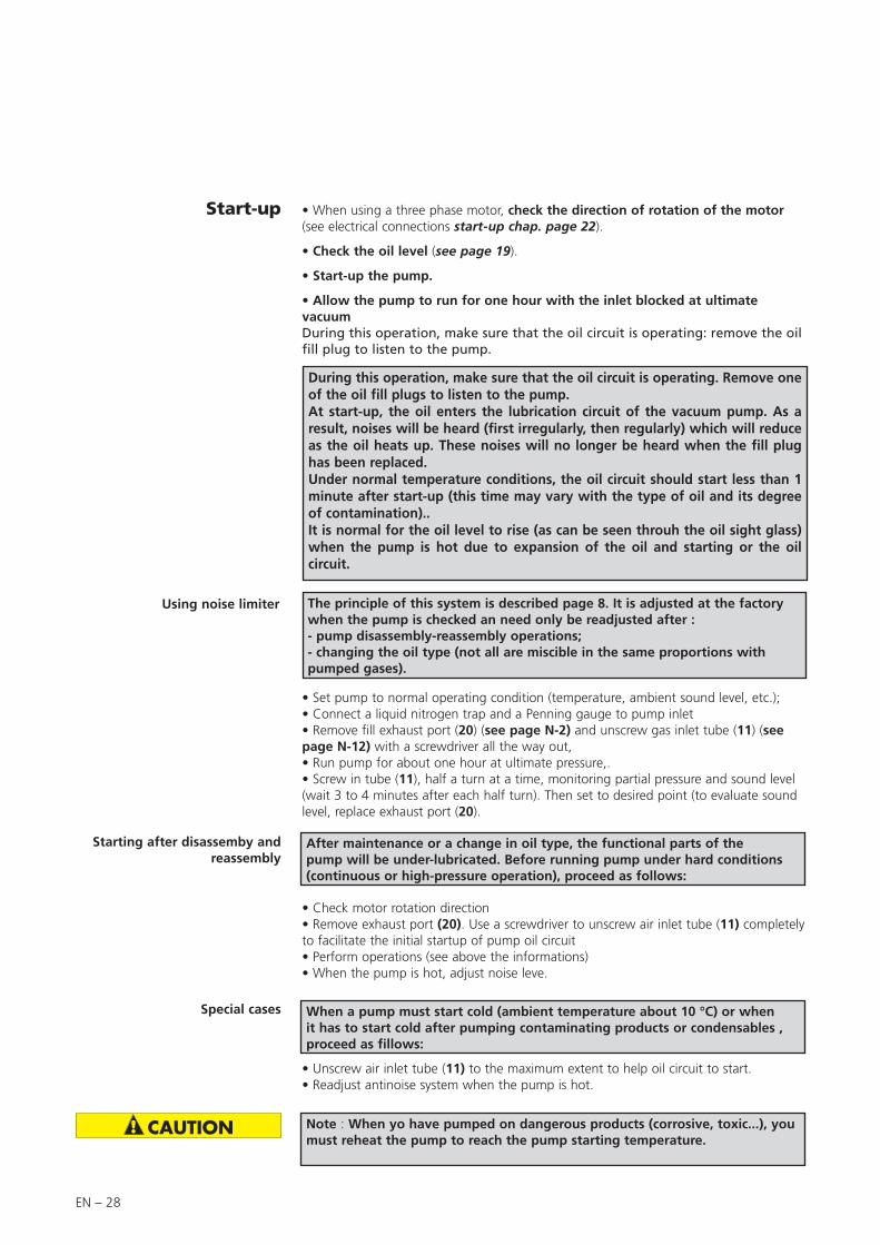
Start-up • When using a three phase motor, check the direction of rotation of the motor (see electrical connections start-up chap. page 22).
• Check the oil level (see page 19).
• Start-up the pump.
• Allow the pump to run for one hour with the inlet blocked at ultimate vacuumDuring this operation, make sure that the oil circuit is operating: remove the oil fill plug to listen to the pump.
Using noise limiter
• Set pump to normal operating condition (temperature, ambient sound level, etc.);• Connect a liquid nitrogen trap and a Penning gauge to pump inlet• Remove fill exhaust port (20) (see page N-2) and unscrew gas inlet tube (11) (see page N-12) with a screwdriver all the way out,• Run pump for about one hour at ultimate pressure,.• Screw in tube (11), half a turn at a time, monitoring partial pressure and sound level (wait 3 to 4 minutes after each half turn). Then set to desired point (to evaluate sound level, replace exhaust port (20).
The principle of this system is described page 8. It is adjusted at the factory when the pump is checked an need only be readjusted after :- pump disassembly-reassembly operations;- changing the oil type (not all are miscible in the same proportions with pumped gases).
Starting after disassemby and reassembly
After maintenance or a change in oil type, the functional parts of the pump will be under-lubricated. Before running pump under hard conditions (continuous or high-pressure operation), proceed as follows:
Special cases
• Unscrew air inlet tube (11) to the maximum extent to help oil circuit to start.• Readjust antinoise system when the pump is hot.
• Check motor rotation direction• Remove exhaust port (20). Use a screwdriver to unscrew air inlet tube (11) completely to facilitate the initial startup of pump oil circuit• Perform operations (see above the informations)• When the pump is hot, adjust noise leve.
When a pump must start cold (ambient temperature about 10 °C) or when it has to start cold after pumping contaminating products or condensables , proceed as fillows:
Note : When yo have pumped on dangerous products (corrosive, toxic...), you must reheat the pump to reach the pump starting temperature.
During this operation, make sure that the oil circuit is operating. Remove one of the oil fill plugs to listen to the pump.At start-up, the oil enters the lubrication circuit of the vacuum pump. As a result, noises will be heard (first irregularly, then regularly) which will reduce as the oil heats up. These noises will no longer be heard when the fill plug has been replaced.Under normal temperature conditions, the oil circuit should start less than 1 minute after start-up (this time may vary with the type of oil and its degree of contamination)..It is normal for the oil level to rise (as can be seen throuh the oil sight glass) when the pump is hot due to expansion of the oil and starting or the oil circuit.

EN – 29
EN
Op
era
tio
n
Oxygen pumping
In certain applications, mixtures containing oxygen at different concentrations, or even pure oxygen, are used.
Oils of mineral origin are combustible. Exposure to pure oxygen at high temperatures may cause them to self-ignite. In addition, they are highly oxidized during pumping and quickly lose their lubricating properties. Mineral oils must not be used for oxygen levels of over 21 % in pumped gases. In this case, perfluorinated synthetic oils must be used, see list on page 17.
The use of these oils requires a special pump preparation (see page 37). The pump must be completely disassembled and all traces oil mineral oil removed. Flushing the oil case is not adequate.
Any accumulation of oxygen in the installation should be avoided and the oxygen or combustible mixture should be diluted with a neutral gas at the exhaust: the gas flow rate should be 4 times the oxygen flow rate.
Certain combustible or explosive gases require a higher degree of dilution. Our Support Services and Customer Services can advise you to help solve problems of this kind.
In addition, it is strongly recommended not to use fluids such as tri-aryl-phosphate-ester which are known to cause accidents.

EN – 30
Outlet
Electrovalve
Recovery of oil (high pressure and cycling)
For intermittentpumping
When the pump operates at high pressure, the oil heats up, becomes more fluid and is flushed out of the functional block by the gas stream.
Oil losses at the exhaust are increased.
If the pump only operates for a very short time at high pressure, the lubricating oil is replaced when the pump returns to low pressure. The use of a oil mist eliminator prevents losses due to intermittent high pressure operation.
If the pump operates at high pressure in a cyclical fashion, oil consumption may reach sufficiently high levels (according to the pumped volume and pumping cycle rates) causing the level to drop in the oil case.
There is then a risk of seizure due to a lack of oil. In addition, the high flow of gas passing through the eliminator prevents oil from returning to the oil case.
In order to pump in these conditions, the pump must be equipped with an oil mist eliminator and an oil draining kit, which enables oil recovery via the gas ballast.Please consult us directly.
For continuous pumping at high
pressure
For cyclical pumping
In this case, or when very large volumes (requiring several hours of pumping) are being pumped, it is recommended to recover the oil via the pump inlet.
In this case, please consult us directly.
OME 40 H oil mist eliminator with ODK oil recovery deviceAn electrovalve ensure the tightness when the pump is stopped
Inlet

EN – 31
EN
Main
ten
an
ce
General precautions
Maintenance
For normal operation, the maintenance of 2033-2063 m3/h series pumps only require regular oil changes (see page 35).
Always dispose of used dirty oil, or sub-products properly and in compliance with all local, state and federal environmental laws and regulations.
Certain gases can become corrosives and toxic when trapped in oil. Always wear protective gloves when handling used and dirty pump oil, drain it into a closable container,and do not breathe the fumes of the oil. Always use fully self-contained breathing apparatus.
Before any draining or maintenance operation, check the pumping conditions of the installation: potential toxicity, corrosion or radioacitivity of pumped gases.Depending on the case, we recommend:– to purge the pumping installation with dry nitrogen before maintenance;– wear gloves, protective goggles and, if necessary, a breathing apparatus;– ventilate the premises well and disassemble the equipment under a suction
hood;– not to dispose of used oils and residues using the standard system and, if
necessary, have them destroyed by a specialized company.
After a complete maintenance operation, it is recommended to perform a helium leak tightness test.The manufacturer can provide specific training to know the tightness test methods and supply helium leak detectors. Contact us.
Decontamination – product dismantlingAccording to the regulations 2002/96/CE about Waste of electrical and electronical equipments, and 2002/95/CE about Restriction of Hazardous substances, the manufacturer provides a recycling paid service for the end-of-life of waste electrical and electronic equipment.Any obligation of the manufacturer to take back such equipment shall apply only to complete not amended or modified equipment, using Alcatel Vacuum Technology original spare parts, delivered by Alcatel Vacuum Technology, containing i.e. all its components and sub-assemblies. This obligation will not cover the shipping cost to an Alcatel take back facility.Before returning the product, fill in the safety form, attach it to the product before shipping to the service-repair office closest to you.Safety form available on this manual or can be downloaded on: www.adixen.com

EN – 32
Incidents Causes Corrective actions
The pump is not running Incorrect motor power supply. Check the power supply.
Temperature too low. Reheat the pump and its oil.
Gumming of seals after prolonged storage.
Disassemble the motor and try to turn the fan manually.Disassemble, clean the pump, replace seals, reassemble.
Oil contaminated after pumping. Drain, flush and refill with cleanoil.
Motor coupling damaged. Replace by disassembling the motor.
Pump seized, due to a stopping after pumping in difficult conditions (no draining or flushing).
Disassemble, clean, hone the scratched metal parts (replace them if necessary) and reassemble.
The pump does not start Oil cold. Warm pump.
Insufficient oil in the oil case. Fill up to the level.
Oil contaminated. Drain, flush and refill with cleanoil.
Oil pump inlet partially blocked. Drain, and clean the oil pump inlet duct.
Lubrication holes blocked. Disassemble and clean.
Vane or spinner-cam (SD models) damaged.
Replace them.
Incorrect anti-suckback system assembly.
Repeat the assembly and the setting.
The vacuum pump does not produce a vacuum
Ultimate pressure obtained: a few mbar, Torr
Direction of motor rotation incorrect (three phase).
Rewire.
Insufficient motor power. Check the power supply.
Inlet filter blocked. Clean it.
Insufficient oil in the oil case. Add oil.
Oil cold, oil pump inlet blocked. Warm, disassemble, clean.
Oil contaminated. Drain, flush and start again with clean oil.
Oil pump inlet partially blocked. Drain and clean the oil pump inlet duct.
One of the LP safety valves is damaged.
Replace.
Part forgotten in reassembly. Repeat the reassembly.
Troubleshooting and corrective actions

EN – 33
EN
Main
ten
an
ce
Incidents Causes Corrective actions
The vacuum pump does not produce a vacuum (continued)
Ultimate pressure obtained: a few 10-2 Torr (10-2 mbar)
O-ring pinched. Replace.
One of the seals is damaged. Replace.
One of the HP safety valves is damaged.
Replace.
Lubrication holes blocked. Disassemble and clean.
Incorrect anti-suckback assembly. Repeat the assembly and setting.
Part forgotten in reassembly. Repeat the reassembly.
Accessories
At the pump exhaust, the installation produces an exhaust pressure of 1,125 Torr (1.5 bar).
Check the installation.
Oil mist eliminator cartridge clogged. Replace.
Noisy pump Oil level too high. Drain and fill with a new oil.
Oil contaminated (presence of particles).
Drain, flush and refill with cleanoil.
Pump not prepared for the oil used. Check the pump configuration or the type of oil.
Incorrect motor power supply. Check the power supply.
Motor bearings damaged. Replace the motor after inspection.
Motor coupling incorrectly set or damaged.
Check the setting.
Incorrect fan assembly. Check the assembly.
Incorrect anti-suckback device assembly.
Repeat the assembly.
Vanes damaged or stuck. Replace.
Pump too hot Ambient temperature too high.
Pump placed in a poorly ventilated place or vents blocked.
Check the installation.
Operation at high pressureP > 22 Torr (30 mbar).
Check for system leaks.
Excess pressure at exhaust. Check the exhaust line.
Motor in over-voltage or motor in short-circuit.
Check the voltage, replace the motor.
Oil contaminated. Drain, flush and refill with cleanoil.
Pump not prepared for the oil used or oil unsuitable.
Check pump configuration or type of oil.

EN – 34
Incidents Causes Corrective actions
Considerable oil losses Oil level too high. Drain and fill with new oil.
Operation at high pressure. Use an HP type oil mist eliminator with oil recovery.
Leak at oil case seal or at front seal. Check the assembly and replace the seals if necessary.
Safety valve damaged. Replace.
Incorrect anti-suckback assembly. Repeat the assembly.
O-ring pinched. Replace.
Seals damaged. Replace.
Oil contaminated. Drain, flush and refill with cleanoil.
Oil in plate Oil case and frame cleaned poorly during reassembly.
Remove the base and clean.
Oil case seal pinched. Disassemble the oil case, clean the faces and refit a new seal.
Front seal damaged or felt saturated. Replace.
Oil level variation External shaft seal deterioration Replace shaft seal
Discharge at surpressure: oil level from sealed housing rises, casing oil level falls
Replace shaft seals 14, 15 and 18.
Discharge at low pressure: casing oil level rises, sealed housing level falls
Replace shaft seals 14, 15 and 18.

EN – 35
EN
Main
ten
an
ce
Maintenance
Maintenance frequency
Frequency Operating conditions
Oil6 months “normal”, 24 / 24h
1 year “normal”, < 12h / day
Pump1 year “normal”, 24 / 24h
2 years “normal”, < 12h / day
The frequency values are minimum values for «normal» operating conditions: pressure < 1 mbar (0.75 Torr), clean gas and non-corrosive gas.
An incorrect ultimate vacuum or a reduction in pumping speed are signs that the oil has deteriorated.The periodic inspection of the state of the oil is performed by comparison with a sample of new oil in order to check the level of contamination or deterioration of the lubricant.The frequency at which oil is renewed is adapted to the type of operation:– if the oil is cloudy, this indicates that condensables have been absorbed during
pumping. – a thickening of the oil, together with a blackish color and a “burnt” smell indicate
that the oil has deteriorated.Drain the pump and flush it.
The oil should be changed every 6 months. This value is given as a guide only. It may be extended to 1 year if the ultimate vacuum required is sufficient (for primary vacuum pumps). Similarly, if the pump is stopped frequently for long periods, the oil should be changed at intervals of 6 months to a maximum of 1 year (oil may become sticky).
Note: Every pumping operation is different. This oil must therefore be changed at intervals adapted to each specific application. The use of certain accessories (see page 13) can reduce the frequency of these maintenance operations.

EN – 36
Draining
The pump must be drained when hot and after the oil case has been vented to atmospheric pressure. For this:
– switch off the pump;
– isolate the pump or disconnect from the installation;
– tilt the pump;
– unscrew the draining plug (A) on the side of the oil case and the filling plug (B) on the top of the oil case.
When all the oil has drained, replace the two plugs temporarily and run the pump for about 10 seconds leaving the intake open. Take care with the oil mist which may appear at the exhaust. This operation removes the oil from the functional block;
– drain this oil by removing the draining plug;
– replace the draining plug and fill with fresh oil to the appropriate maximum level of the oil case oil sight glass through the filling orifice (C) (see page 19).
The draining operation places the contaminated pumping circuit in communication with the outside atmosphere. Take all necessary steps to ensure personal safety.
A
C
BOil case draining
Sealed housing draining
Unscrew the filling plug (B) on the top of the sealed housing and the draining plug (A) on the side of the sealed housing.
When all the oil has drained, replace the draining plug (A) and fill with fresh oil to the appropriate maximum level of sealed housing oil sight glass (C) through the filling orifice.Replace the filling plug (B) A
C
B
Flushing The draining operation can be followed by a flushing operation if the oil is particularly dirty. This operation requires a volume of oil equal to the capacity of the pump.
After draining the sealed housing, replace the draining plug. Remove the intake filter, clean it and replace it. Run the pump at atmospheric pressure, pour the flushing oil very slowly through the inlet orifice. Take care with oil mist which may develop at the exhaust. Stop the pump and drain the flushing oil via the draining plug. Replace the plug and fill with fresh oil (see page 18)

EN – 37
EN
Main
ten
an
ce
2033 H1 and 2063 H1 pumps are tested in the factory with A120 oil or A119 for USA unless specified otherwise in the order. When the pump is delivered, a certain quantity of oil remains in the functional block.Thus, if you wish to use another type of oil, proceed as follows:
Mineral oil can be replaced by another type of mineral oil. Simply flush the pump (see page 36) using the new oil and fill the pump (see page 18).Mineral oils are also compatible with mineral-based synthetic oils (see page 17).
This is the case when, for example, a mineral oil is replaced by a synthetic oil (e.g. A120 by A113).Synthetic oils are considered to be incompatible with each other for practical reasons: they are expensive. A mixture may cause slight cloudiness of the resulting mixture, which could be interpreted mistakenly as a sign of contamination or deterioration.For the same reasons, clear synthetic and mineral oils (A300), which are also expensive, are treated as synthetic oils.
These remarks apply to ester or fluorocarbon type synthetic oils and the oils A111, A113 and A300 (see page 17).
Proceed as follows:– Disassemble the pump completely and clean it (see page 40).– Reassemble it.– Connect an oil mist eliminator to the pump exhaust.– Fill the pump (oil case and sealed housing) with the new oil (see page 18).
NOTE: to replace a synthetic oil by a mineral oil, proceed as for compatible oils.
Incompatible oils
Compatible oils
Change of type of oil
In all cases, follow the recommendations of the pump integrators for the choice of the oil to be used.

EN – 38
Tools and consumable products
Special precautions
Major kit
Spare parts
This kit contains all the seals on the pump which must be replaced at each complete disassembly.
Keep this kit in a dry place, away from heat and light (sunlight and ultraviolet light), in order to prevent any hardening of the elastomers (see AFNOR standards: “storage conditions for vulcanized elastomer based products” - FD T.46 022).
Pump 2033 H1 2063 H1
P/N 054282 054483
In addition to the seal kit, this kit contains a set of spare parts to perform maintenance operations on the pump for a two year period, under normal operating conditions.
Pump 2033 H1 2063 H1
P/N 054283 054484
Read the warning at the beginning of the maintenance chapter.Before disassembling the pump, drain it (see page 34).All the seals and faulty parts should be replaced, provided in a seal kit or a maintenance kit.
Minor kit
For fasted servcice, specify the following when ordering:- pump type- serialnumber (on label)- part number (see list at end of book)
Maintenance kits containing the most frequently used parts are always available at our sales outlets. Be sure to use these kits so you will have all the parts necessary.
Screw kit This kit contains all screws and washers for the pump.
Pump models P/N
2033 H1 / 2063 H1 105347

EN – 39
EN
Main
ten
an
ce
Recommended tools The tools required for disassembling and reassembling the motor pump asssembly are listed below:
• N° 3 and N° 9 screwdrivers
• Thin spanner: 13-17 mm on face
• Allen wrenches: - 4 - 5 - 6 - 8 mm
• 6 mm and 8mm extraction screws
• Slip-joint pliers
Tools kit This kit contains the usefull tools to disassemble and reassemble the shaft seals in the different flanges and flanged stators (see table bellow).
Pump models P/N
All pumps 065192
Specific tools
Protective sleeve
Description P/N
Mounting mandrel 065089
Protective sleeve 065088
Washer 073331
Coupling adjustment tool 065087
Extraction tool 065186

EN – 40
Disassembling the pump
Disassembling the motor block
(see page N-2)
Unscrew 4 nuts (59)
Remove motor assembly (49) and motor mounting plate (53). The coupling separates into two halves, one (51) on the motor side , the other (52) on the pump side.
FollOw the chronological order of disassembling instructions.See the drawings and their part lists in pages N – 1 to N – 15
Disassembling the exhaust valve cover
(see page N – 8)
Remove the screws (7) (10) and the cover(s) (5) (11), the exhaust valves (2) (13) and their springs (4) (12).
Remove 4 nuts (17).Insert two screwdrivers into the two notches and twist to remove palte off pins. Pull flange (14) straight out, hodling HP rotor (35) in place.Remove O-ring (43) (see page N – 8).
Disassembling therear flange (see page N-12)
Remove screws (1) (2) and body (18).
Remove srews (3) (4) and cylinder (5), spring (23), the piston (22) and diaphragm (21).Remove seat (20) and O-ring (19).
Remove screw (8) (9) and remove the air retening retainer (10).Remove oil inlet tube (6).Unscrew air inlet tube (11) and remove spring (12).
(If necessary, note settting of air inlet tube (11): number of turns until tube stops moving turning clokwise).
Remove vane (38) (see page N – 8).
Disassembling the pump oil system
(see page N – 12)
19
3
5
20
21
23 22
4
Disassembling moving parts
(see page N-2)
Prevent fan (64) from rotating by wedging a wooden chock against the side of the frame and two blades of the fan.
Remove elastomere coupling (52).Unscrew self-locking srew (62) not (reusable) and remove washer (63)Using two 8 mm extraction screws, remove fan (64) and schockRemove screws (65) and using two 6 mm extraction screws, remove cover (67) with seal (48).
Removing the oil case
(see page N – 2)
Unscrew the nuts (29) and remove the oil casing (25) and its gasket (28).
Gasket may cause case (25) and frame (34) to stick together due to aging: insert lever between base and bottom of case, and pry off case . Do not use a hammer or screwdriver, which could dammage the parts and sealing surfaces.
Disassembling the oil sight glass
(see page N – 2)
Unscrew the sight glass (14). Remove the the O-rings (13) (15), the ring (11) , the sight glass (12).

EN – 41
EN
Main
ten
an
ce
Disassembling the pumping module
Remove the HP rotor (35) by skiding it out of the HP stator (40).Remove vanes (37) and their springs (36).Insert two screwdrivers in the two notches of the HP stator (40) and twist to remove plate off pins. Remove HP stator (40) straight out. Remove the O-ring (34).
Removing HP rotor (35) and HP stator (40)
(see N – 8)
Removing flange (33) (see N – 8)
Insert two screwdrivers in the notches of the flange (33) and release the flange (33) . Remove the O-ring (31).Oil jet (32) lubricates the first stage . Do not remove it for cleaning. When reassembling, spray with compresses air to remove any obstructions.Remove tube (29) and O-ring. (28).
Removing LP rotor (23) and LP stator (27)
(see N – 8)
Remove the LP rotor (23) by sliding it out of the LP stator (27).Remove vanes (25) and their springs (24).Insert two screwdrivers in the notches of the LP stator (27) and twist to remove the LP stator (27) straight out. Remove the O-ring (26).
Removing front flange (21)(see N – 8))
Remove 4 nuts (32) (see N – 2).Insert two screwdrivers in the notches of the flange (21) and twist to remove the front flange (21) straight out. Remove the O-ring (19), shaft seal (15) (18) and the gib rings (16) (17).
Disassembling inlet nipple (20) on oil case(see N – 2)
To remove exhaust nipple (20), the nipple must be connected to a line wih a NW 40 centering ring with O-ring and quick connect clam. Use the quick connect clam to unscrew the nipple (20).Remove O-ring (24).Remove pin (17) filter (18), shaft (19), valve (22) and circlip (23).
Disassembling inlet nipple (40) on frame (34)
(see N – 2)
Remove 4 screws (41) and remove clamps (44).Remove nipple (40), the inlet filter (38) and its O-ring (39).

EN – 42
Cleaning components
Cleaning metal components
Cleaning the oil level sight glass
Solvents are required to clean components.
Standard precautions should be taken in compliance with the manufacturer's instructions.
After use in mineral or synthetic oil, clean the metal components with a mineral products based solvent such as AXAREL(1) , CARECLEAN(2), PREMACLEAN(3), NAPHTESOL(4). Proceed as follows:• Clean when cold or hot (max. 45°C) by dipping or using a cloth• Vacuum dry in a ventilated oven• The component must be cleaned a second time with alcohol.
After use in (perfluorinate) synthetic oil, clean the metal components in a solvent such as GALDEN S 90™(5) and proceed as follows:• Clean when cold by dipping or using a cloth• Dry the components in the air or with compressed air
After use in (non-perfluorinate) synthetic or mineral oil, clean the metal components with a solvent such as alcohol and proceed as follows:• Clean when cold by dipping or using a cloth• Dry the components in the air• Industrial washing solutions can also be used. The cleaning operation should be
followed by vacuum drying.
The sight glass of these pumps is made of glass: it can be cleaned with common used solvents.
(1) DUPONT DE NEMOURS registered trademark(2) CASTROL registered trademark(3) DOW registered trademark(4) Nippon Oil Corporation registered trademark(5) MONTEDISON registered trademark

EN – 43
EN
Main
ten
an
ce
Replacement of shaft seals
Recommended tools
Direction of assemblyof shaft seals
Assembling the shaft seal
Extracting a shaft seal from its housing
Mandrel
Specific toolswasher
ø 34.5 ± 0.1
5.5 ± 0.2
ø 19.5 +0.20 1
à 45 C
+0.20
Assembly the protective sleeve
Sleeve
• Specific extraction tool.• Specific assembly mandrel.• A support plate (or washer).
• A flat screwdriver .• A hammer.
• Flange : the seal is extracted using a screwdriver, resting on the plate (or washer) so as not to damage the seal housing.
The seal housing and the seal lip are lubricated with the lubricant used in the pump.The flange is resting on a flat surface.
According to the direction of assembly specific to each pump, the seal is fitted on the assembly mandrel.
Using a press or a hammer, the seal is inserted in its housing.
Check the position of the seal: it must lean against its bearing.
Lip seals
Double lip seal
Resting rings
To install the flanges, use protective sleeve and oil it before mounting lange (or wrap end of shaft with adhesive tape).
They are fitted using the assembly mandrel according to the direction of assembly below: (seals and resting rings).
Frame
LP rotor
HP Stator LP stator
Rear fl ange
Front fl ange
Seal-holder
Central fl ange

EN – 44
Reassembling the pump
• All parts must be dry so that no solvent remains, particularly in blind holes• Check that the lubrication holes are not blocked.• Oil used for lubricate pump parts must be the same as oil used for pumpoperation.
Component preparation
Before reassembly • Coat all pump parts and lips of shaft seals with clean oil. Make sure seals are correctly installed (see page 43). • Fill lubrication holes of bearings and seal seats with oil.• Do not put too much oil in the bottoms of the holes for the plate/stator alignments pins.• Tighten nuts without forcing maximum torque (see chapter «Nomenclature»)• Rest the frame (34) on a flat surface in order to raise the pump..
The bushings in the frame and plates can be replaced, but special machining is required whenever a bushing is changed. Consult service center for assistance.
Assembling moving parts
• Reassemble moving parts in reverse order of disassembly.• Before replacing valves, for a little oil into the stators through the valve holes.• Before reassembling oil pump, assemble fan (64) using a new self-locking screw totighten it (Maintenance kit page 38).
Assembling oil pump
Rotor38
Mount all necessary parts on oil pump body proceeding in reverse order as described page 40.Place slot of oil pump rotor in horizontal position (parallel to pump base).Fan can be used to turn rotor, but never insert a screwdriver in the rotor slot as this may cause damage.Place vane (38) in its slot. With pump horizontal, let pump body drop by gravity on to rotor.With pump vertical, turn pump body (18) clockwise around alignment pin (13), to bring it into contact with the rotor without forcing. Never rest pump body on rotor; this will eliminate bearing play.Fit two screws (1a) and (1b): must be tightened first (1a), and (1b) second (maximum torque: 10 N.m.)
1a
13
18
1b

EN – 45
EN
Main
ten
an
ce
Air inlet tube Screw the air tube home (11) and unscrew it of the number of turns given, whendisassembling (usually 3 or 4 turns) (see page 40).
Motor coupling To make sure motor coupling does nottouch fan, adjust distance from motorplate (dimension A on the drawing) :To perform this adjustment, useadjusting tool in tool kit (see page 39).
pump Dimension «A»
2033 H1 16,6 ± 0.5 mm
2063 H1 23,3 ± 0.5 mm
A
After reassembling, fill the oil casing and the sealed housing with oil (see page 18) before start-up the pump (see page 26).
Fill with oil

EN – 46

EN – 47
EN
Main
ten
an
ce
Safety questionnaire
Procedure for returning ADIXEN productsYou wish to return an Adixen product for maintenance. The equipment will be dismantled and possibly cleaned by a technician from our Service Centre.In compliance with European Community’s L360 directives, French labor code L231 - R231 and Federal OSHA Safety Standard 1910-1200, Alcatel Vacuum Technology requires this form to be completed to preclude the potential health risk to its service personnel that can occur when receiving, disassembling, or repairing potentially contaminated products.
Equipment returned without this form completed and secured to outside of package will be returned to customer unprocessed.Equipment must be drained of fluids and residue, securely packaged and shipped prepaid.Concerning the closing of the ports (inlet & outlets of the product), metallic airtight blank flanges should be used if toxic or copper gases have been pumped.
We wish to draw your attention to the following points:
• The risk may be of the following nature:- Chemical: Danger to health, risks of explosion, fire, risks for the environment. Please indicate the chemical formula and
name of the gases or substances that have been in contact with the equipment (pump or detector).- Biological: in case of contamination (such as pathogenic germs, micro-organisms (bacteria, viruses, etc.) classes 1 to 4 and
group E), our Service Center is currently unable to decontaminate and recycle such material without risk to the safety of our staff. Please contact us before sending the product to the Service center.
- Radioactive: In case of contamination, our Service Center is currently unable to decontaminate and recycle such material without risk to the safety of our staff. Please contact us before sending the product to the Service center.
- Copper contamination: Copper based by products formed in sputtering or etching processes are considered as a poison in some semi-conductor processes.
If following inspection and quotation, customer elects to not proceed with repair, he will be subject to service fee to cover product decontamination, disassembly, cleaning and evaluation costs.
Please to fill in the following form, print it and attach it to the product before shipping to the service-repair office closest to you.
• Gases (or substances) introduced into the reactor and which may be found at the exhaust (A).• Gases (or substances) resulting from the reaction or process (B).• Gases (or substances) that may possibly be formed inside the pump (due to a thermodynamic or chemical reaction,
condensation, deposition, precipitation, etc.) (C).
• Precautions need to be taken before transferring contaminated pumps. Please contact Service Center for recommendations.
In the event of chemical contamination, please indicate the following gases or substances:
Gasesintroduced
A
Substances produced by reaction
Pump or pump unit
ExhaustABCB
Reactor C

EN – 48

EN – 49
EN
Main
ten
an
ce

N – 1
Nomenclature
Composants de maintenance / Maintenance components2033 H1 - 2063 H1
Plan de montage cuve et bâti .............................................Oil casing and central housing assembly drawing ........................................................................................................................2 / 6
Nomenclature cuve et bâti ..................................................Oil casing and central housing part list .................................................................................................................................. 3 / 5 / 7
Plan du bloc fonctionnel .....................................................Pumping module drawing ........................................................................................................................................................8 / 10
Nomenclature du bloc fonctionnel ......................................Pumping module part list .........................................................................................................................................................9 / 11
Plan du système de lubrification pompe à huile (A) .............Oil pump system drawing (A) .........................................................................................................................................................12
Nomenclature du système de lubrification .........................Oil pump system part list (A) ...........................................................................................................................................................13pompe à huile (A)
Plan ensemble motorisation (M) ..........................................Motor assembly drawing (M) ..........................................................................................................................................................14
Nomenclature ensemble motorisation (M) ...........................Motor assembly part list (M) ...........................................................................................................................................................14

N – 2
5354
55
6061
6263
6465
6667
76
75
74
73
72
71
70
69
7
8
9
10
16
1112
1314
15
1718
2427
2829
3031
33 35
36
37
39
40
41
12
3
4
5
6
68
3421
22
2320
19
25
26
49
52
5051
5657
5859
80797877 81
38
47
46
44
43
42
45
48
32
Plan de montage cuve et bâtiOil casing and central housing assembly drawing
Rep. PartClamping torque
(N.m)
29/32/36/59 Nut HM10 11
31 Stud HM 10-30/22Stud HM 8-28/18
15
33 Stud HM 10-55/22Stud HM 8-50/20
15
50 Screw HC M6-12 8
61 Stud HM 10-25/20Stud HM 8-20/15
15
62 Screw CHc M10 30
55/76 Screw CHc M8 x 20Screw CHc M8 x 25
15

N – 3
Nomenclature
Nomenclature cuve et bâti / Oil casing and central housing part list
REP DÉSIGNATION SPECIFICATIONTypes/model REF.
P/N2033 H1 2063 H11 Joint torique 2.7*16.9 O-ring 2.70*16.9 1/3 1/3 2 Bouchon 3/8 G Drain plug 3/8 1/3 1/3 0527523 Joint torique 2.70 * 18.4 O-ring 2.70 *18.4 1/2 1/2 4 Douille d'étanchéité Tightness spacer 1/2 1/2 0655285 Ecrou HM 18 Nut HM 18 1/2 1/2 -6 Rac. embout male 1/8G 1/8G male fitting 1/2 1/2 -7 Idem 6 Idem 6 1/2 1/2 -8 Ecrou HM 18 Nut HM 18 1/2 1/2 -9 Idem 4 Idem 4 1/2 1/2 065528
10 Idem 3 Idem 3 1/2 1/2 11 Circlips D38 Circlips D38 1 1 12 Disque verre Glass disc 1 1 05419913 Joint torique 3.6*37.3 O-ring 3.6 *37.3 1 1 14 Corps voyant huile Oil sight glass body 1 1 -15 Joint torique 3*44 O-ring 3*44 2/3 2/3 16 Bouchon mâle Fill plug 1 1 05421317 Goupille V1.6 -10 Pin V1.6 -10 1 1 -18 Filtre de refoulement équipé Equipped exhaust filter 1 1 10011619 Axe refoulement Exhaust valve shaft 1 1 05422320 Embout de refoulement DN 40 ISO KF Exhaust nipple DN 40 ISOKF 1 1 05420521 Protecteur Protective cap 1/2 1/2 -22 Soupape Valve 1 1 23 Clips Circlips 1 1 05413324 Idem 15 Idem 15 1/3 1/3 25 Cuve Oil case 1 -25 Cuve Oil case 1 -26 Rondelle M6 Washer M6 1 1 -27 Refroidisseur Cooler 1 05427427 Refroidisseur Cooler 1 06552628 Joint torique 5*220 O-ring 5*220 1 28 Joint torique 5*241 O-ring 5*241 1 29 Ecrou HM10 Nut HM10 6/20 6/20 30 Rondelle Ond.8 Washer D8 4/28 6/28 31 Goujon M8-28/18 Stud M8-28/18 6/6 05420931 Goujon M10-30/22 Stud M10-30/22 6/6 05444132 Idem 29 Idem 29 4/20 4/20 33 Goujon M8-50/20 Stud M8 -50/20 4/4 05426633 Goujon M10-55/22 Stud M10-55/22 4/4 06551534 Bâti Central housing 1 -34 Bâti Central housing 1 -35 Idem 30 Idem 30 2/28 2/28 36 Idem 29 Idem 29 2/20 2/20
Lot joints / Minor kit Lot maintenance / Major kit Lot visserie / Screw kit

N – 4
Rep. PartClamping torque
(DaN.m)
2 Screw FHC M5 x 10 0.4
9 Screw CHC M6 x 25 1.2
14 / 20 Screw FHC M6 x 12 1
28 Screw M5 x 16 (s.steel) 0.6
38 Screw CHC M6 x 12 1.1
45 Screw CHC M6 x 25 1.2
52 / 57 Screw CHC M4 x 10 0.4
5354
55
6061
6263
6465
6667
76
75
74
73
72
71
70
69
7
8
9
10
16
1112
1314
15
1718
2427
2829
3031
33 35
36
37
39
40
41
12
3
4
5
6
68
3421
22
2320
19
25
26
49
52
5051
5657
5859
80797877 81
38
47
46
44
43
42
45
48
32
Plan de montage cuve et bâtiOil casing and central housing assembly drawing
Rep. PartClamping torque
(N.m)
29/32/36/59 Nut HM10 11
31 Stud HM 10-30/22Stud HM 8-28/18
15
33 Stud HM 10-55/22Stud HM 8-50/20
15
50 Screw HC M6-12 8
61 Stud HM 10-25/20Stud HM 8-20/15
15
62 Screw CHc M10 30
55/76 Screw CHc M8 x 20Screw CHc M8 x 25
15

N – 5
Nomenclature
REP DÉSIGNATION SPECIFICATIONTypes/model REF.
P/N2033 H1 2063 H137 Anneau levage Eye hook 2/2 08300437 Anneau levage Eye hook 2/2 08269738 Filtre aspiration Inlet filter 1/1 05420238 Filtre aspiration Inlet filter 1/1 05442639 Joint torique 5.33*40.64 O-ring 5.33*40.64 1/1 1/1 40 Embout d'aspiration DN 40 ISO KF Inlet nipple DN 40 ISO KF 1 1 05423241 Vis CHc M6-20 Screw Chc M6-20 1/4 1/4 42 Protecteur Protective cap 1/2 1/2 -43 Rondelle D6 Washer D6 1/13 1/13 44 Taquet Intake clamp 4 4 06850445 Idem 2 Idem 2 1/3 1/3 05275246 Idem 1 Idem 1 1/3 1/3 47 Joint torique 2.5*74 O-ring 2.5*74 1/1 1/1 48 Joint double lèvre 20*35*7 Double lip seal 20*35*7 1/1 1/1 49 Moteur Motor 1/1 1/1 page 12-1350 Vis HC M6-12 Screw HC M6-12 1/1 1/1 -51 Manchon moteur Motor coupling 1/1 05411651 Manchon moteur Motor coupling 1/1 05443652 Anneau élastique denté Elastic coupling 1/1 1/1 53 Flasque moteur Motor flange 1/1 05411853 Flasque moteur Motor flange 1/1 05441954 Rondelle Washer 4/4 4/4 55 Vis Chc M8-20 Screw CHc M8-20 4/4 -55 Vis Chc M8-25 Screw CHc M8-25 4/4 -56 Grille de protection Motor flange screen 1/1 05426456 Grille de protection Motor flange screen 1/1 06551157 Déflecteur air Deflector 1/1 05414757 Déflecteur air Deflector 1/1 05443258 Vis FS M6-10 Screw FS M6-10 3/3 3/359 Idem 29 Idem 29 4/20 4/20 60 Idem 30 Idem 30 4/28 4/28 61 Goujon M8-20/15 Stud M8-20/15 4/4 07583761 Goujon M10-25/20 Stud M10-25/20 4/4 07583862 Vis CHc M10*20 Screw CHc M10*20 1/1 1/1 63 Rondelle Schnorr D10.5*23 Washer Schnorr D10.5 *23 1/1 1/1 64 Ventilateur Fan 1/1 05411564 Ventilateur Fan 1/1 05443565 Vis CHc M6-12 Screw CHc M6-12 3/3 3/3 66 Rondelle OND D6 Washer D6 3/13 3/13 67 Couvercle porte joint Cover 1/1 05424567 Couvercle porte joint Cover 1/1 06522268 Aiguille D6-12 Cotter D6-12 2/2 07104168 Aiguille D8-12 Cotter D8-12 2/2 071046
Nomenclature cuve et bâti / Oil casing and central housing part list
Lot joints / Minor kit Lot maintenance / Major kit Lot visserie / Screw kit

N – 6
Rep. PartClamping torque
(DaN.m)
2 Screw FHC M5 x 10 0.4
9 Screw CHC M6 x 25 1.2
14 / 20 Screw FHC M6 x 12 1
28 Screw M5 x 16 (s.steel) 0.6
38 Screw CHC M6 x 12 1.1
45 Screw CHC M6 x 25 1.2
52 / 57 Screw CHC M4 x 10 0.4
5354
55
6061
6263
6465
6667
76
75
74
73
72
71
70
69
7
8
9
10
16
1112
1314
15
1718
2427
2829
3031
33 35
36
37
39
40
41
12
3
4
5
6
68
3421
22
2320
19
25
26
49
52
5051
5657
5859
80797877 81
38
47
46
44
43
42
45
48
32
Plan de montage cuve et bâtiOil casing and central housing assembly drawing
Rep. PartClamping torque
(N.m)
29/32/36/59 Nut HM10 11
31 Stud HM 10-30/22Stud HM 8-28/18
15
33 Stud HM 10-55/22Stud HM 8-50/20
15
50 Screw HC M6-12 8
61 Stud HM 10-25/20Stud HM 8-20/15
15
62 Screw CHc M10 30
55/76 Screw CHc M8 x 20Screw CHc M8 x 25
15

N – 7
Nomenclature
REP DÉSIGNATION SPECIFICATIONTypes/model REF.
P/N2033 H1 2063 H169 Joint torique 2.70*16.9 O-ring 2.70*16.9 1/3 1/3 70 Idem 2 Idem 2 1/3 1/3 05275271 Vis HM 10-12 Screw HM 10-12 4/4 4/4 -72 Rondelle Ond D10 Washer D10 4/28 4/28 73 Socle Base 1/1 05410273 Socle Base 1/1 05440874 Butée Shock mount 4/4 4/4 05332375 Idem 30 Idem 30 4/28 4/28 76 Vis CHc M8-20 Screw CHc M8-20 4/10 76 Vis CHc M8-25 Screw CHc M8-25 8 77 Joint torique 2*21 O-ring 2*21 1 1 78 Corps voyant huile Oil sight glass body 1 1 79 Joint torique 3.6*19.8 O-ring 3.6*19.8 1 1 80 Disque pyrex Pyrex disc 1 1 81 Circlips Clips 1 1
Nomenclature cuve et bâti / Oil casing and central housing part list
Lot joints / Minor kit Lot maintenance / Major kit Lot visserie / Screw kit

N – 8
40
4342
41
3938
3736
3534
33
3231
30
27
26
2524
2322
21
201913
12
11
2
3
4
5
1
8
14
1516
1718
6
7
9
10
2829
Plan du bloc fonctionnelPumping module drawing
Rep. PartClamping torque
(N.m)
7 Screw CHC M6 x 45 6
10 Screw CHC M6 x 45 6
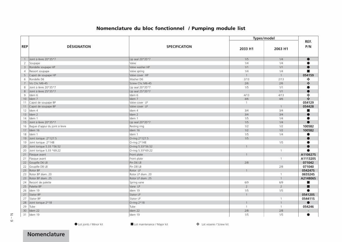
N – 9
NomenclatureNomenclature
Lot joints / Minor kit Lot maintenance / Major kit Lot visserie / Screw kit
REP DÉSIGNATION SPECIFICATION
Types/modelREF.P/N
2033 H1 2063 H1
1 Joint à lèvre 20*35*7 Lip seal 20*35*7 1/5 1/4 2 Soupape Valve 1/4 1/4 3 Rondelle soupape HP Valve washer HP 1/1 1/1 4 Ressort soupape Valve spring 1/4 1/4 5 Capot de soupape HP Valve cover HP 1 1 0541596 Rondelle D6 Washer D6 2/13 2/13 7 Vis Chc M6-45 Screw Chc M6-45 2/6 2/6 8 Joint à lèvre 20*35*7 Lip seal 20*35*7 1/5 1/1 8 Joint à lèvre 25*35*7 Lip seal 25*35*7 1/19 Idem 6 Idem 6 4/13 4/13 10 Idem 7 Idem 7 4/6 4/6 11 Capot de soupape BP Valve cover LP 1 05412911 Capot de soupape BP Valve cover LP 1 05442812 Idem 4 Idem 4 3/4 3/413 Idem 2 Idem 2 3/4 3/4 14 Idem 1 Idem 1 1/5 1/4 15 Joint à lèvre 20*35*7 Lip seal 20*35*7 1/5 1/4 16 Bague d'appui du joint à lèvre Resting ring 1/2 1/2 10058217 Idem 16 Idem 16 1/2 1/2 10058218 Idem 1 Idem 1 1/5 1/4 19 Joint torique 2*127.5 O-ring 2*127.5 1/5 19 Joint torique 2*148 O-ring 2*148 1/5 20 Joint torique 5.33 *56.52 O-ring 5.33*56.52 1 20 Joint torique 5.33 *69.22 O-ring 5.33*69.22 1 21 Flasque avant Front plate 1 A110627S21 Flasque avant Front plate 1 A111320S22 Goupille D6 L8 Pin D6 L8 2/8 07104222 Goupille D8 L8 Pin D8 L8 2/8 07104023 Rotor BP Rotor LP 1 054247S23 Rotor BP diam. 20 Rotor LP diam. 20 1 065524S23 Rotor BP diam. 25 Rotor LP diam. 25 1 A214806S24 Ressort de palette Spring vane 6/9 6/925 Palette BP Vane LP 2 226 Idem 19 Idem 19 1/5 1/5 27 Stator BP Stator LP 1 054120S27 Stator BP Stator LP 1 054411S28 Joint torique 2*18 O-ring 2*18 1 1 29 Tube Tube 1 1 05424630 Idem 22 Idem 22 2/8 2/8 -31 Idem 19 Idem 19 1/5 1/5
Nomenclature du bloc fonctionnel / Pumping module list

N – 10
40
4342
41
3938
3736
3534
33
3231
30
27
26
2524
2322
21
201913
12
11
2
3
4
5
1
8
14
1516
1718
6
7
9
10
2829
Plan du bloc fonctionnel Pumping module drawing
Rep. PartClamping torque
(N.m)
7 Screw CHc M6 x 45 6
10 Screw CHc M6 x 45 6

N – 11
Nomenclature
REP DÉSIGNATION SPECIFICATION
Types/modelREF.P/N
2033 H1 2063 H1
32 Gicleur médian Jet int. plate 1 08799732 Gicleur médian Jet int. plate 1 06500133 Flasque médian diam. 20 Intermediate flange diam. 20 1 054121S33 Flasque médian diam. 20 Intermediate flange diam. 20 1 054413S33 Flasque median diam. 25 Intermediate flange diam. 25 1 A110543S34 Idem 19 Idem 19 1/5 1/5 35 Rotor HP Rotor HP 1 054125S35 Rotor HP diam. 20 Rotor HP diam. 20 1 054433S35 Rotor HP diam. 25 Rotor HP diam. 25 1 A214808S36 Ressort de palette Vane spring 3/9 3/9 37 Palette Vane 2 2 38 Palette de pompe à huile Oil pump vane 1 1 39 Idem 22 Idem 22 2/8 2/8 -40 Stator HP Stator HP 1 054122S40 Stator HP Stator HP 1 054415S41 Frein d'axe Circlip 1 1 42 Idem 22 Idem 22 2/8 2/8 -43 Idem 19 Idem 19 1/5 1/5
Lot joints / Minor kit Lot maintenance / Major kit Lot visserie / Screw kit
Nomenclature du bloc fonctionnel / Pumping module list

N – 12
19
21
2
23
1
17
18
6
3
45
78
910
1112
13
14
15
16
22
20
Plan du système de lubrification pompe à huile Oil pump system drawing
Rep. PartClamping torque
(N.m)
1 Screw CHc M 8 x 40 11
3 Screw CHc M 5 x 8 40
15 Stud M10 137.5/26 15
15 Stud M8-105/20 11

N – 13
Nomenclature
Nomenclature du système de lubrification pompe à huile / Oil pump system part list
Sous-ensemble A / Subassembly A / Gesamtplan A
REP DÉSIGNATION SPECIFICATION
Types/modelREF.P/N
2033 H1 2063 H1
1 Vis CHc M 8-40 Screw CHc M 8-40 2/2 2/2 2 Rondelle Ond D8 Washer D8 2/2 2/2 3 Vis CHc M 5-8 Screw CHc M 5-8 2/2 2/2 4 Rondelle D5 Washer D5 2/2 2/2 5 Cylindre Cylinder 1/1 1/1 0830776 Tube prise d'huile Oil admission tube 1/1 -6 Tube prise d'huile Oil admission tube 1/1 -7 Gliceur Jet 1/1 1/1 0542418 Vis CHc M 5-12 Screw CHc M 5-12 1/1 1/1 9 Rondelle Ond D5 Wavy washer D5 1/1 1/1 10 Butée tube entrée d'air Stop for air admission tube 1/1 1/1 06551011 Tube de prise d'air Air admission tube 1/1 1/1 05421212 Ressort Spring 1/1 1/113 Goupille D6 L8 Pin D6 L8 1/1 1/1 07104014 Flasque arrière Rear flange 1/1 054250S14 Flasque arrière Rear flange 1/1 065505S15 Goujon M8-105/20 Stud M8-105/20 4/4 05420815 Goujon M10-137.5/26 Stud M10-137.5/26 4/4 05444316 Rondelle Ond D8 Washer D8 4/4 16 Rondelle Ond D10 Washer D10 4/4 17 Ecrou HM 8 Nut HM 8 4/20 17 Ecrou HM10 Nut HM 10 4/20 18 Corps de pompe à huile Oil pump body 1/1 05425318 Corps de pompe à huile Oil pump body 1/1 06551319 Joint torique 2.7*10.5 O-ring 2.7*10.5 1/1 1/1 20 Siège Seat 1/1 1/1 05414421 Membrane Membrane 1/1 1/1 22 Piston Piston 1/1 1/1 08333123 Ressort Spring 1/1 1/1
Lot joints / Minor kit Lot maintenance / Major kit Lot visserie / Screw kit

N – 14
Nomenclature ensemble motorisation (M) / Motor assembly part list (M)
M
1
Plan ensemble motorisation (M)Motor assembly drawing (M)
REP DÉSIGNATION SPECIFICATION
Types/modelREF.P/N
2033 H1 2063 H1
1 Clavette Shaft key 1/1 1/1 -M1 Moteur triphasé EUROPE 1.1/1.3 kW - 190/480V - 50/60Hz - 1500/1800 tr/mn Tree-phase motor EUROPE 1.1/1.3 kW - 190/480V - 50/60Hz - 1500/1800 tr/mn 1/1 118059M2 Moteur triphasé EUROPE 2.2/2.6 kW - 190/480V - 50/60Hz - 1500/1800 tr/mn Tree-phase motor EUROPE 2.2/2.6 kW - 190/480V - 50/60Hz - 1500/1800 tr/mn 1/1 118060M3 Moteur triphasé USA/JAPAN 1.1/1.3 kW - 175/460V - 50/60Hz - 1500/1800 tr/mn Tree-phase motor USA/JAPAN 1.1/1.3 kW - 175/460V - 50/60Hz - 1500/1800 tr/mn 1/1 113114M4 Moteur triphasé USA/JAPAN 2.2/2.6 kW - 175/460V - 50/60Hz - 1500/1800 tr/mn Tree-phase motor USA/JAPAN 2.2/2.6 kW - 175/460V - 50/60Hz - 1500/1800 tr/mn 1/1 113115M5 Moteur triphasé ASIA/ROW 1.1/1.3 kW - 180/480V - 50/60Hz - 1500/1800 tr/mn Tree-phase motor ASIA/ROW 1.1/1.3 kW - 180/480V - 50/60Hz - 1500/1800 tr/mn 1/1 114449M6 Moteur triphasé ASIA/ROW 2.2/2.6 kW - 180/480V - 50/60Hz - 1500/1800 tr/mn Tree-phase motor ASIA/ROW 2.2/2.6 kW - 180/480V - 50/60Hz - 1500/1800 tr/mn 1/1 114450

CHINAAlcatel Vacuum Technology, ShanghaiN°82 Lane 887 Zuchongzhi RoadZhangjiang High-Tech Park,Shanghai 201203 ChinaTel. (86) 21 5027 0628Fax. (86) 21 3895 3815
FRANCEAlcatel Vacuum Technology France98, avenue de Brogny - BP 206974009 Annecy cedexFranceTel. (33) 4 50 65 77 77Fax. (33) 4 50 65 77 89
GERMANYAlcatel Hochvakuumtechnik GmbHAm Kreuzeck 10 - Postfach 115197877 Wertheim GermanyTel. (49) 9342 9610 0Fax. (49) 9342 9610 30
ITALYAlcatel Vacuum SystemsVia Trento, 3020059 Vimercate (Mi) ItalyTel. (39) 0396 86 38 55Fax. (39) 039 66 71 25
Alcatel Vacuum Technology France - 98, avenue de Brogny - BP 2069 - 74009 Annecy cedex - FRANCETel. (33) 4 50 65 77 77 - Fax. (33) 4 50 65 77 89
Web site: www.adixen.com
JAPANAlcatel-Lucent Japan Ltd.1-9-4 Kita Shin-YokohamaKohoku-kuYokohama, Kanagawa 223-0059JapanTel. (81) 3 6431 7130Fax. (81) 45 544 0049
KOREAAlcatel Vacuum Technology Korea447 Banwol-dong, Hawsung-si,445-330 Kyungki-do,South KoreaTel. (82) 031-206-6277Fax. (82) 031-204-6279
NETHERLANDSALCATEL Vacuum Technology Benelux Landzichtweg 60NL 4105 DP CulemborgThe NetherlandsTel. (31) 345 478 400Fax. (31) 345 531 076
SINGAPOREAlcatel-Lucent Singapore49 Jalan Pemimpin#01-02 APS Industrial Building577203SingaporeTel. (65) 6254 0828Fax. (65) 6254 7018
SWEDENAdixen Sensistor AB.Box 76 SE-581 02 LinköpingSweden Tel. 46 (0)13 35 59 00Fax. 46 (0)13 35 59 01
TAIWANAlcatel Vacuum Technology TaïwanNo. 169-3, Sec.1, Kang-Leh RdSong-Lin Village, Hsin-Feng 304Hsin-Chu CountyTaïwan - R.O.C.Tel. (886) 3 559 9230Fax.(886) 3559 9231
UNITED KINGDOMAlcatel Vacuum Technology UK Ltd8 Bain Square - Kirkton CampusLivingston - West LothianEH54 7DQ - ScotlandUnited KingdomTel. (44) 1 506 418 000Fax. (44) 1 506 418 002
USAAlcatel Vacuum Products67, Sharp StreetHingham - MA 02043USATel. (1) 781 331 4200Fax. (1) 781 331 4230