parts you are fitting so please skip to the appropriate 1 ... · pdf fileparts you are fitting...
TRANSCRIPT

Jan-12 dynoset-hub-ds
HUB DYNAMO LIGHTING SYSTEMS, FITTING OF PARTS.
1. Fitting the hub dynamo wheel
The fitting of the hub dynamo
wheel is similar regardless of the
hub type (Shimano F703 shown).
Insert the hub dynamo wheel
into the fork dropouts with the
contacts on the right hand side
of the bike.
The contacts should be pointing
forwards at 90 degrees
to the dropouts (fig EL05).
Replace with the same tab-washers off the old wheel but discard any plain M8 washers.
Insert the skewer bolt through the front axle bush then the RH tab-washer (tab facing fork) and into
the axle from the right hand side. Note: Some P-types have a special RH tab-washer that will need
to be refitted in place of the standard RH tab-washer to protect the control cables when folded.
On the left hand side add the LH tab-washer with the hook wire-form nested inside it. With the
knurled detail outermost, screw on the axle nut to retain the wire-form and tighten by hand. Ensure
the axle is seated properly (as far as it will go into the drop out slots) and tighten bolt with a 4mm
hex drive to 8N m maximum while keeping the wheel central between the forks.
Wheel building
If building your own Brompton wheel, parts are available individually as shown below.
Dynamo Hub Spokes as standard Lacing Nipples
Shimano F703 Hub only
Part: QFWHUBDYN-SHMNO
Plain gauge 14swg Length = 135mm
Part: QSPOKFSS-SHMNO One cross Steel
SON XS Hub only
Part: QFWHUBDYN-SON
Double butted 14swg Length = 137mm
Part: QSPOKFSS-SON One cross Aluminium
Read First
This data sheet includes fitting instructions for all hub
dynamo parts by covering procedures on fitting an entire hub dynamo set in order. It may well contain
information which is not relevant to the individual
parts you are fitting so please skip to the appropriate
section listed on the right.
Sections
1) Fitting the Hub Dynamo Wheel
2) Fitting the Front Lamp Bracket 3) Fitting and connecting the Front Lamp
4) Routing and securing the Rear Loom
5) Fitting the Rear Lamp
New Set Bolt = 102mm
Old Set Bolt = 100mm
Fig AF02 LEFT RIGHT
Important: the skewer bolt set incorporating the bush
and nut has been revised on bikes from 2010 onwards.
The bolt is slightly longer and the bush and nut slightly
larger (fig AF02). The new ‘larger’ sets can be used on any
hollow axle hubs from Brompton regardless of age but the
older ‘smaller’ sets must not be used with the Shimano
F703 hub dynamo.
Be sure to replace with the new set provided and
discard the old set. If the wrong set is used the
front wheel may not be secured safely!
Right hand side Left hand side
Fig EL05
Bush
LH Tab Washer
Nut
Hook Wire-Form
RH Tab Washer
Bolt
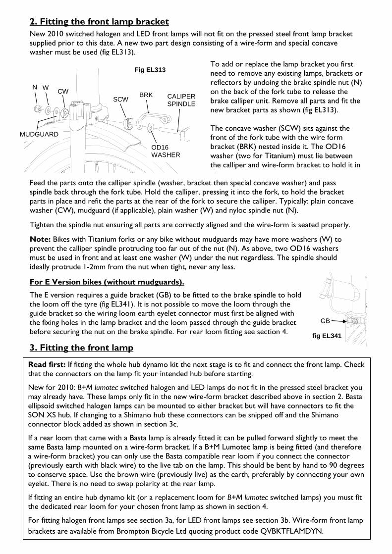
2. Fitting the front lamp bracket
New 2010 switched halogen and LED front lamps will not fit on the pressed steel front lamp bracket
supplied prior to this date. A new two part design consisting of a wire-form and special concave
washer must be used (fig EL313).
Feed the parts onto the calliper spindle (washer, bracket then special concave washer) and pass
spindle back through the fork tube. Hold the calliper, pressing it into the fork, to hold the bracket
parts in place and refit the parts at the rear of the fork to secure the calliper. Typically: plain concave
washer (CW), mudguard (if applicable), plain washer (W) and nyloc spindle nut (N).
Tighten the spindle nut ensuring all parts are correctly aligned and the wire-form is seated properly.
Note: Bikes with Titanium forks or any bike without mudguards may have more washers (W) to
prevent the calliper spindle protruding too far out of the nut (N). As above, two OD16 washers
must be used in front and at least one washer (W) under the nut regardless. The spindle should
ideally protrude 1-2mm from the nut when tight, never any less.
For E Version bikes (without mudguards).
The E version requires a guide bracket (GB) to be fitted to the brake spindle to hold
the loom off the tyre (fig EL341). It is not possible to move the loom through the
guide bracket so the wiring loom earth eyelet connector must first be aligned with
the fixing holes in the lamp bracket and the loom passed through the guide bracket
before securing the nut on the brake spindle. For rear loom fitting see section 4.
3. Fitting the front lamp
To add or replace the lamp bracket you first
need to remove any existing lamps, brackets or
reflectors by undoing the brake spindle nut (N)
on the back of the fork tube to release the
brake calliper unit. Remove all parts and fit the
new bracket parts as shown (fig EL313).
The concave washer (SCW) sits against the
front of the fork tube with the wire form
bracket (BRK) nested inside it. The OD16
washer (two for Titanium) must lie between
the calliper and wire-form bracket to hold it in
place.
Fig EL313
CW
SCW
W BRK
MUDGUARD
OD16 WASHER
N
CALIPER SPINDLE
fig EL341
GB
Read first: If fitting the whole hub dynamo kit the next stage is to fit and connect the front lamp. Check
that the connectors on the lamp fit your intended hub before starting.
New for 2010: B+M lumotec switched halogen and LED lamps do not fit in the pressed steel bracket you
may already have. These lamps only fit in the new wire-form bracket described above in section 2. Basta
ellipsoid switched halogen lamps can be mounted to either bracket but will have connectors to fit the
SON XS hub. If changing to a Shimano hub these connectors can be snipped off and the Shimano
connector block added as shown in section 3c.
If a rear loom that came with a Basta lamp is already fitted it can be pulled forward slightly to meet the
same Basta lamp mounted on a wire-form bracket. If a B+M Lumotec lamp is being fitted (and therefore
a wire-form bracket) you can only use the Basta compatible rear loom if you connect the connector
(previously earth with black wire) to the live tab on the lamp. This should be bent by hand to 90 degrees
to conserve space. Use the brown wire (previously live) as the earth, preferably by connecting your own
eyelet. There is no need to swap polarity at the rear lamp.
If fitting an entire hub dynamo kit (or a replacement loom for B+M lumotec switched lamps) you must fit
the dedicated rear loom for your chosen front lamp as shown in section 4.
For fitting halogen front lamps see section 3a, for LED front lamps see section 3b. Wire-form front lamp
brackets are available from Brompton Bicycle Ltd quoting product code QVBKTFLAMDYN.
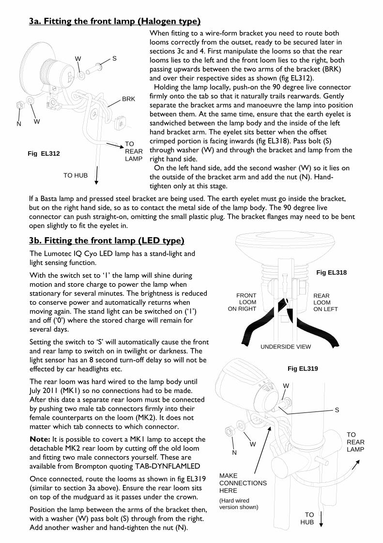
3a. Fitting the front lamp (Halogen type)
If a Basta lamp and pressed steel bracket are being used. The earth eyelet must go inside the bracket,
but on the right hand side, so as to contact the metal side of the lamp body. The 90 degree live
connector can push straight-on, omitting the small plastic plug. The bracket flanges may need to be bent
open slightly to fit the eyelet in.
3b. Fitting the front lamp (LED type)
W S
BRKK
TO HUB
TO REAR LAMP
Fig EL312
N W
When fitting to a wire-form bracket you need to route both
looms correctly from the outset, ready to be secured later in
sections 3c and 4. First manipulate the looms so that the rear
looms lies to the left and the front loom lies to the right, both
passing upwards between the two arms of the bracket (BRK)
and over their respective sides as shown (fig EL312).
Holding the lamp locally, push-on the 90 degree live connector
firmly onto the tab so that it naturally trails rearwards. Gently
separate the bracket arms and manoeuvre the lamp into position
between them. At the same time, ensure that the earth eyelet is
sandwiched between the lamp body and the inside of the left
hand bracket arm. The eyelet sits better when the offset
crimped portion is facing inwards (fig EL318). Pass bolt (S)
through washer (W) and through the bracket and lamp from the
right hand side.
On the left hand side, add the second washer (W) so it lies on
the outside of the bracket arm and add the nut (N). Hand-
tighten only at this stage.
Fig EL318
REAR LOOM ON LEFT
FRONT LOOM
ON RIGHT
UNDERSIDE VIEW
The Lumotec IQ Cyo LED lamp has a stand-light and
light sensing function.
With the switch set to ‘1’ the lamp will shine during
motion and store charge to power the lamp when
stationary for several minutes. The brightness is reduced
to conserve power and automatically returns when
moving again. The stand light can be switched on (‘1’)
and off (‘0’) where the stored charge will remain for several days.
Setting the switch to ‘S’ will automatically cause the front
and rear lamp to switch on in twilight or darkness. The
light sensor has an 8 second turn-off delay so will not be
effected by car headlights etc.
The rear loom was hard wired to the lamp body until
July 2011 (MK1) so no connections had to be made.
After this date a separate rear loom must be connected
by pushing two male tab connectors firmly into their
female counterparts on the loom (MK2). It does not
matter which tab connects to which connector.
Note: It is possible to covert a MK1 lamp to accept the
detachable MK2 rear loom by cutting off the old loom
and fitting two male connectors yourself. These are
available from Brompton quoting TAB-DYNFLAMLED
Once connected, route the looms as shown in fig EL319
(similar to section 3a above). Ensure the rear loom sits
on top of the mudguard as it passes under the crown.
Position the lamp between the arms of the bracket then,
with a washer (W) pass bolt (S) through from the right.
Add another washer and hand-tighten the nut (N).
Fig EL319
S
N
W
W
TO HUB
TO REAR LAMP
MAKE CONNECTIONS HERE
(Hard wired version shown)

3c. Connecting the front lamp to the hub (Halogen and LED type)
The following procedure is to electrically connect the front lamp to the hub and secure the front
loom. Fixing of the front loom is the same for all types of lamp but there is a different connection
method depending on your hub.
To fit the Shimano connector plug
First separate the grey part (A) from the black part (B) by depressing the small tab in the hole at the
back. Observing the correct polarity is unnecessary so Insert each wire until the insulation just passes
the inner hole and bend the bare strands sharply upwards, keeping them neat and confined to the
grooves in part A. Ensure the two bare ends do not touch each other and press part A into part B.
If you have a SON XS dynamo hub simply push on the connectors as far as they will go. The
connectors can go either way round and can fit to either tab. When removing SON connectors hold
them as low down as possible to avoid stressing the wires. Gently work them side to side without
using a jerking action or bending the conectors.
Switch on the lamp and check that it works by spinning the wheel a little. If the lamp does not shine
or flicker, re-check all connections.
If necessary bend the bracket down a little so that it does not foul on the headset bearing cup.
Loop L should be sculpted into the neatest arrangement regardless of connector type.
Typically Basta halogens and the Lumotec IQ
Cyo LED lamp will have connectors for the
SON XS hub dynamo, where the Lumotec halogen lamp will have a connector plug for
the Shimano F703 hub dynamo already fitted.
It is possible to convert SON XS connectors
to accept a Shimano connector. Cut where
shown (fig EL320) to leave as much wire as
possible, pull off the remaining heat shrink
and strip 13mm of insulation of the end.
Fig EL321
TO REAR LAMP
TW
L
Securing the front lamp
As a guide, the lens of most lamps should be perpendicular
to the axis of the front frame tube as shown. Once
positioned, tighten the lamp mounting bolt fully and check
there is ample clearance to avoid the mudguard and/or any
luggage option. The bracket can be tweaked into the
correct position using gentle bending and twisting.
Securing the front loom
The front loom passes over the right hand bracket arm and
down the right hand fork blade (fig EL321). First slide the
outer sleeve right up to the lamp body and loosely position
the longest tie wrap at the top (TW). Manipulate the loom
above TW so that it just clears the calliper and secure TW
tightly. Connect the plug to the hub by pressing it on firmly
until it clicks in place. The plug will only fit one way round.
Place the middle tie wrap just above the mudguard-stay-tab
and the lower tie wrap to leave an adequate loop (L) to
allow for easy disconnection when removing the wheel.
fig EL320
CUT
PULL
STRIP
A
B
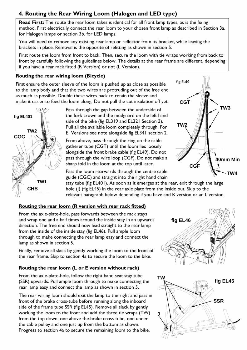
fig EL45
CHS
TW
J
SSR
4. Routing the Rear Wiring Loom (Halogen and LED type)
Routing the rear wiring loom (Bicycle)
First ensure the outer sleeve of the loom is pushed up as close as possible
to the lamp body and that the two wires are protruding out of the free end
as much as possible. Double these wires back to retain the sleeve and make it easier to feed the loom along. Do not pull the cut insulation off yet.
Pass through the gap between the underside of
the fork crown and the mudguard on the left hand
side of the bike (fig EL319 and EL321 Section 3).
Pull all the available loom completely through. For
E Versions see note alongside fig EL341 section 2.
From above, pass through the ring on the cable
gatherer tube (CGT) until the loom lies loosely
alongside the front brake cable (fig EL49). Do not
pass through the wire loop (CGF). Do not make a
sharp fold in the loom at the top until later.
Pass the loom rearwards through the centre cable
guide (CGC) and straight into the right hand chain
stay tube (fig EL401). As soon as it emerges at the rear, exit through the large
hole (J) (fig EL45) in the rear axle plate from the inside out. Skip to the
relevant paragraph below depending if you have and R version or an L version.
Routing the rear loom (R version with rear rack fitted)
From the axle-plate-hole, pass forwards between the rack stays
and wrap one and a half times around the inside stay in an upwards
direction. The free end should now lead straight to the rear lamp
from the inside of the inside stay (fig EL46). Pull ample loom
through to make connecting the rear lamp easy and connect the
lamp as shown in section 5.
Finally, remove all slack by gently working the loom to the front of
the rear frame. Skip to section 4a to secure the loom to the bike.
Routing the rear loom (L or E version without rack)
From the axle-plate-hole, follow the right hand seat stay tube
(SSR) upwards. Pull ample loom through to make connecting the
rear lamp easy and connect the lamp as shown in section 5.
The rear wiring loom should exit the lamp to the right and pass in
front of the brake cross-tube before running along the inboard
side of the frame tube SSR (fig EL45). Remove all slack by gently
working the loom to the front and add the three tie wraps (TW)
from the top down; one above the brake cross-tube, one under
the cable pulley and one just up from the bottom as shown.
Progress to section 4a to secure the remaining loom to the bike.
Read First: The route the rear loom takes is identical for all front lamp types, as is the fixing
method. First electrically connect the rear loom to your chosen front lamp as described in Section 3a.
for Halogen lamps or section 3b. for LED lamps.
You will need to remove any existing rear lamp or reflector from its bracket, while leaving the
brackets in place. Removal is the opposite of refitting as shown in section 5.
First route the loom from front to back. Then, secure the loom with tie wraps working from back to
front by carefully following the guidelines below. The details at the rear frame are different, depending
if you have a rear rack fitted (R Version) or not (L Version).
fig EL46
CGC TW2
CHS
fig EL401
TW1
TW2
fig EL49
TW3
CGF
CGT
40mm Min
TW4
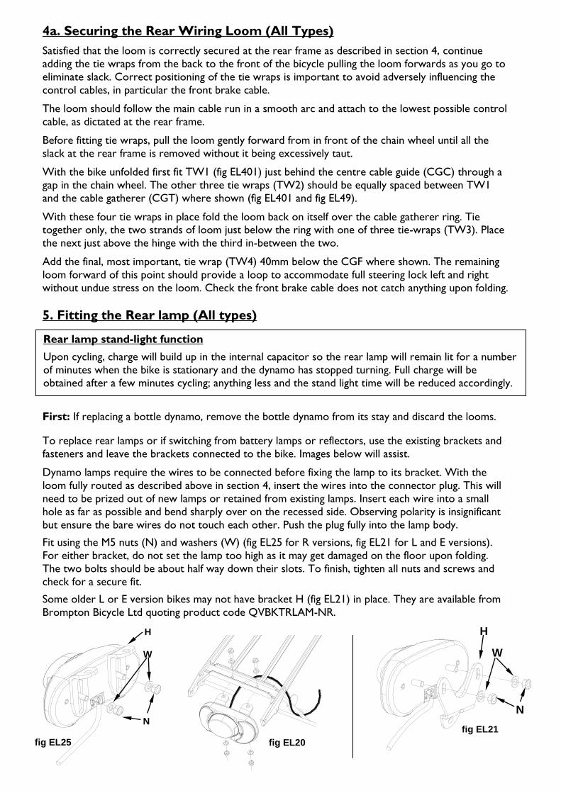
fig EL21
W
H
N
fig EL20
4a. Securing the Rear Wiring Loom (All Types)
Satisfied that the loom is correctly secured at the rear frame as described in section 4, continue
adding the tie wraps from the back to the front of the bicycle pulling the loom forwards as you go to
eliminate slack. Correct positioning of the tie wraps is important to avoid adversely influencing the
control cables, in particular the front brake cable.
The loom should follow the main cable run in a smooth arc and attach to the lowest possible control
cable, as dictated at the rear frame.
Before fitting tie wraps, pull the loom gently forward from in front of the chain wheel until all the
slack at the rear frame is removed without it being excessively taut.
With the bike unfolded first fit TW1 (fig EL401) just behind the centre cable guide (CGC) through a
gap in the chain wheel. The other three tie wraps (TW2) should be equally spaced between TW1
and the cable gatherer (CGT) where shown (fig EL401 and fig EL49).
With these four tie wraps in place fold the loom back on itself over the cable gatherer ring. Tie together only, the two strands of loom just below the ring with one of three tie-wraps (TW3). Place
the next just above the hinge with the third in-between the two.
Add the final, most important, tie wrap (TW4) 40mm below the CGF where shown. The remaining
loom forward of this point should provide a loop to accommodate full steering lock left and right
without undue stress on the loom. Check the front brake cable does not catch anything upon folding.
5. Fitting the Rear lamp (All types)
First: If replacing a bottle dynamo, remove the bottle dynamo from its stay and discard the looms.
To replace rear lamps or if switching from battery lamps or reflectors, use the existing brackets and
fasteners and leave the brackets connected to the bike. Images below will assist.
Dynamo lamps require the wires to be connected before fixing the lamp to its bracket. With the
loom fully routed as described above in section 4, insert the wires into the connector plug. This will
need to be prized out of new lamps or retained from existing lamps. Insert each wire into a small
hole as far as possible and bend sharply over on the recessed side. Observing polarity is insignificant
but ensure the bare wires do not touch each other. Push the plug fully into the lamp body.
Fit using the M5 nuts (N) and washers (W) (fig EL25 for R versions, fig EL21 for L and E versions).
For either bracket, do not set the lamp too high as it may get damaged on the floor upon folding.
The two bolts should be about half way down their slots. To finish, tighten all nuts and screws and
check for a secure fit.
Some older L or E version bikes may not have bracket H (fig EL21) in place. They are available from
Brompton Bicycle Ltd quoting product code QVBKTRLAM-NR.
Rear lamp stand-light function
Upon cycling, charge will build up in the internal capacitor so the rear lamp will remain lit for a number
of minutes when the bike is stationary and the dynamo has stopped turning. Full charge will be
obtained after a few minutes cycling; anything less and the stand light time will be reduced accordingly.
fig EL25
W
N
H