partition operation guide - fujitsumanuals.ts.fujitsu.com/file/6958/partopguide05en.pdf ·...
TRANSCRIPT

Partition Operation Guide
May 2003
C120-E087-05EN


FOR SAFE OPERATIONThis manual contains important information for using this product. Read thoroughly before using the product. Use this product only after thoroughly reading and understanding this manual. Keep this manual handy, and keep it carefully.
FUJITSU makes every effort to prevent users and bystanders from being injured or from suffering damage to their property. Use the product according to this manual.
ABOUT THIS PRODUCTThis product is designed and manufactured for use in standard applications such as office work, personal device, household appliance, and general industrial applications. This product is not intended for use in nuclear-reactor control systems, aeronautical and space systems, air traffic control systems, mass transportation control systems, medical devices for life support, missile launch control systems or other specialized uses in which extremely high levels of reliability are required, the required levels of safety cannot be guaranteed, or a failure or operational error could be life-threatening or could cause physical injury (referred to hereafter as "high-risk" use). You shall not use this product without securing the sufficient safety required for high-risk use. If you wish to use this product for high-risk use, please consult with sales representatives in charge before such use.
C120-E087-05EN

TRADEMARK ACKNOWLEDGEMENTSEthernet is a registered trademark of Fuji Xerox Corporation and Xerox Corporation in the United States and in certain other countries.Sun, Sun Microsystems, Solstice, NFS are trademarks and registered trademarks of Sun Microsystems, Inc., in the United States and in certain other countries.Solaris is a registered trademark of Sun Microsystems, Inc.All SPARC trademarks are trademarks or registered trademarks of SPARC International, Inc., in the United States or certain other countries. Products bearing the SPARC trademarks are based on an architecture originally developed by Sun Microsystems, Inc.All other product names mentioned herein are the trademarks or registered trademarks of their respective owners.Every system and product name in this manual are not always noted with
trademark or registered trademark symbols (TM), ( ).
The contents of this manual may be revised without prior notice.
The contents of this manual shall not be disclosed in any way or reproduced in any media without the express written permission of Fujitsu Limited.
All Rights Reserved, Copyright FUJITSU LIMITED 2000-2003
C120-E087-05EN

Revision History
(1/1)
Edition DateRevised section
(Added/ Deleted/ Altered)Details
01 2000-10-20 02 2001-03-30 2.1.2 (*2.5) (Altered)
3.2 (Added)
Modification of the descriptions of the functions for automatically detecting defects and for automatic switching
Addition of differences in the functions for reconfiguring partitions by rebooting according to the SCSI system version
03 2001-06-18 Totally revised
3.2 (Altered) Modification, 2. Items to check before reconfiguration
04 2003-02-15 Totally revised Addition of description related to extended partitioning and to the PRIMEPOWER900/1500/2500
05 2003-04-24 Totally revised Complete technical review
Note:In this table, a revised section is indicated by its section number in the current edition. An asterisk (*) indicates a section in the previous edition.
C120-E087-05EN


Preface 1
This document provides the user with information necessary to define the partition configuration of GP7000F/PRIMEPOWER high-end models* ("main unit") and for operating that system on the main unit. Use this document to determine the appropriate system configuration before installing this equipment.
This document is intended for system administrators.
* The applicable models are as follows:
GP7000F Model 1000
GP7000F Model 2000
PRIMEPOWER800
PRIMEPOWER900
PRIMEPOWER1000
PRIMEPOWER1500
PRIMEPOWER2000
PRIMEPOWER2500
PRIMEPOWER HPC2500
Confirm your planned system configuration, especially if you plan to use the dynamic reconfiguration (DR) function, with the Fujitsu sales representative before attempting to reconfigure your system.
This document also provides an overview of the DR function. This document is helpful for readers who intend to use DR on other systems as the concepts for configuration of PCI cards and I/O devices that are common to most systems.
This manual mainly applies to PRIMEPOWER models. For information about GP7000F Model 1000/2000, refer to the corresponding manuals for these models.
Precaution when handling this equipmentAsk the Fujitsu engineer responsible for your equipment to mount or remove the system boards. If system boards are mounted or removed by anyone other than a Fujitsu engineer, operation of the system is not guaranteed.
C120-E087-05EN i

Preface
Other Reference ManualsRefer to the following manuals in addition to this manual.
"Dynamic Reconfiguration Architecture Guide PRIMEPOWER/GP7000F" (C120-E114EN)
"Dynamic Reconfiguration User's Guide" (C120-E115EN)"Dynamic Reconfiguration User's Guide I/O Device Edition"
ii C120-E087-05EN

Contents
Preface . . . . . . . . . . . . . . . . . . . . . . . . . . . . . . . . . . . . . . . . . . . . . . . . . . . . . . . . . . . . . . . . . . . i
CHAPTER 1 Definition and Configuration of Partitions . . . . . . . . . . . . . . . . . . . 1
1.1 What Is a Partition? . . . . . . . . . . . . . . . . . . . . . . . . . . . . . . . . . . . . . . . . . . . . 11.1.1 PRIMEPOWER800/1000/2000 partitions . . . . . . . . . . . . . . . . . . . . . 11.1.2 PRIMEPOWER900/1500 partitions . . . . . . . . . . . . . . . . . . . . . . . . . . 21.1.3 PRIMEPOWER2500/HPC2500 partitions . . . . . . . . . . . . . . . . . . . . . 4
1.2 Partition Function of SMC . . . . . . . . . . . . . . . . . . . . . . . . . . . . . . . . . . . . . . . 51.3 Definition of Partition Configuration . . . . . . . . . . . . . . . . . . . . . . . . . . . . . . . . 6
1.3.1 hostid . . . . . . . . . . . . . . . . . . . . . . . . . . . . . . . . . . . . . . . . . . . . . . . . . 61.3.2 Mounting requirements . . . . . . . . . . . . . . . . . . . . . . . . . . . . . . . . . . . . 6
1.4 Key Points When Determining the Partition Configuration . . . . . . . . . . . . . . 71.5 Extended Partitioning (XPAR) . . . . . . . . . . . . . . . . . . . . . . . . . . . . . . . . . . . . 10
1.5.1 Function overview . . . . . . . . . . . . . . . . . . . . . . . . . . . . . . . . . . . . . . . . 101.5.2 System board, CPU, and PCI numbers . . . . . . . . . . . . . . . . . . . . . . . 11
CHAPTER 2 Guidelines for Determining Partition Configuration . . . . . . . . . 15
2.1 Policy on Maintenance of the System Board . . . . . . . . . . . . . . . . . . . . . . . . . 152.1.1 Connecting SMC . . . . . . . . . . . . . . . . . . . . . . . . . . . . . . . . . . . . . . . . 152.1.2 Configuration with high availability . . . . . . . . . . . . . . . . . . . . . . . . . . . 17
2.1.2.1 Redundant configuration . . . . . . . . . . . . . . . . . . . . . . . . . . . . . . 172.1.2.2 Partition definition . . . . . . . . . . . . . . . . . . . . . . . . . . . . . . . . . . . 19
2.1.3 Connection of the PCI card to the system board . . . . . . . . . . . . . . . . 20
2.2 Solaris TM OE Release . . . . . . . . . . . . . . . . . . . . . . . . . . . . . . . . . . . . . . . . . 212.3 Connection of System Volumes . . . . . . . . . . . . . . . . . . . . . . . . . . . . . . . . . . . 21
2.3.1 PRIMEPOWER800/1000/2000 . . . . . . . . . . . . . . . . . . . . . . . . . . . . . 212.3.2 PRIMEPOWER900/1500/2500 . . . . . . . . . . . . . . . . . . . . . . . . . . . . . 252.3.3 PRIMEPOWER HPC2500 . . . . . . . . . . . . . . . . . . . . . . . . . . . . . . . . . 25
2.4 Connecting the Console Connection Unit (CCU) . . . . . . . . . . . . . . . . . . . . . 25
CHAPTER 3 How to Change the Partition Configuration . . . . . . . . . . . . . . . . . 29
3.1 Reconfiguration Function . . . . . . . . . . . . . . . . . . . . . . . . . . . . . . . . . . . . . . . . 293.2 Partition Reconfiguration by Rebooting . . . . . . . . . . . . . . . . . . . . . . . . . . . . . 303.3 Operating the Partitions . . . . . . . . . . . . . . . . . . . . . . . . . . . . . . . . . . . . . . . . . 34
3.3.1 Adding a partition . . . . . . . . . . . . . . . . . . . . . . . . . . . . . . . . . . . . . . . . 353.3.2 Deleting a partition . . . . . . . . . . . . . . . . . . . . . . . . . . . . . . . . . . . . . . . 353.3.3 Dividing a partition . . . . . . . . . . . . . . . . . . . . . . . . . . . . . . . . . . . . . . . 363.3.4 Combining partitions . . . . . . . . . . . . . . . . . . . . . . . . . . . . . . . . . . . . . . 37
C120-E087-05EN iii
Contents
3.4 Operating the System Board . . . . . . . . . . . . . . . . . . . . . . . . . . . . . . . . . . . . . 383.4.1 Adding a system board . . . . . . . . . . . . . . . . . . . . . . . . . . . . . . . . . . . . 393.4.2 Deleting a system board . . . . . . . . . . . . . . . . . . . . . . . . . . . . . . . . . . . 393.4.3 Exchanging system boards . . . . . . . . . . . . . . . . . . . . . . . . . . . . . . . . . 403.4.4 Moving a system board . . . . . . . . . . . . . . . . . . . . . . . . . . . . . . . . . . . . 40
3.5 Notes on Changing the Partition Configuration . . . . . . . . . . . . . . . . . . . . . . . 41
Glossary . . . . . . . . . . . . . . . . . . . . . . . . . . . . . . . . . . . . . . . . . . . . . . . . . . . . . . . . . . . . . . . . . . 43
iv C120-E087-05EN

C120-E087-05EN v
Contents
Figures
Figure 1.1 PRIMEPOWER800/1000/2000 system board configuration . . . . . . 2Figure 1.2 PRIMEPOWER900/1500 system board configuration . . . . . . . . . . . 3Figure 1.3 PRIMEPOWER2500/HPC2500 system board configuration . . . . . . 4Figure 1.4 Moving a system board . . . . . . . . . . . . . . . . . . . . . . . . . . . . . . . . . . . . . . 8
Figure 2.1 Connecting SMC . . . . . . . . . . . . . . . . . . . . . . . . . . . . . . . . . . . . . . . . . . . 16Figure 2.1 Connecting SMC . . . . . . . . . . . . . . . . . . . . . . . . . . . . . . . . . . . . . . . . . . . 17Figure 2.2 Connection configuration and hot system replacement of
a SCSI unit(Relationship with PCI SCSI card: One-to-one connection configuration) . . . . . . . . . . . . . . . . . . . . . . . . . . 22
Figure 2.3 Connection configuration and hot system replacement of SCSI unit (Relationship with PCI SCSI card: Two-to-one connection configuration) . . . . . . . . . . . . . . . . . . . . . . . . . . 23
Figure 2.4 Connection configuration and hot system replacement of SCSI unit (Relationship with PCI SCSI card: Two-to-two connection configuration) . . . . . . . . . . . . . . . . . . . . . . . . . . 24
Figure 2.5 Connections of the console connection unit (CCU) . . . . . . . . . . . . . . 26
Figure 3.1 Types of partition operations . . . . . . . . . . . . . . . . . . . . . . . . . . . . . . . . . . 34Figure 3.2 Types of system board operations . . . . . . . . . . . . . . . . . . . . . . . . . . . . . 38

vi C120-E087-05EN
Contents
Tables
Table1.1 System board numbers, CPU numbers, and PCI numbers used in PPAR mode and those used in XPAR mode (PRIMEPOWER HPC2500/2500) . . . . . . . . . . . . . . . . . . . . . . . . . . 11
Table1.2 System board numbers, CPU numbers, and PCI numbers used in PPAR mode and those used in XPAR mode (PRIMEPOWER1500). . . . . . . . . . . . . . . . . . . . . . . . . 12
Table1.3 System board numbers, CPU numbers, and PCI numbers used in PPAR mode and those used in XPAR mode (PRIMEPOWER900). . . . . . . . . . . . . . . . . . . . . . . . . . 13
Table 2.1 Connection interface between network instance and processing unit. . . . . . . . . . . . . . . . . . . . . . . . . . . . . . . . . . . . . . . . . 16
Table 2.2 PCI cards that require that the main power of the I/O devices be turned off . . . . . . . . . . . . . . . . . . . . . . . . . . . . . . 20
Table 2.3 Parameters specifiable for tty-conspath and tty-sub-conspath . . . . 27
Table 3.1 SCS version and partition reconfiguration . . . . . . . . . . . . . . . . . . . . . . 30Table 3.2 Type of system configuration and effectiveness of
system board addition and removal. . . . . . . . . . . . . . . . . . . . . . . . . 41

CHAPTER 1 Definition and Configuration of Partitions
1
This chapter describes the partition function provided by PRIMEPOWER and the items necessary to determine the system configuration.
1.1 What Is a Partition?
PRIMEPOWER provides a partitioning function for dividing system resources.
If this function is used to partition system resources, operating system can be performed independently in each partition.
Each partition is protected by hardware so it will not be affected by operations on other partitions. Therefore, if a fault (such as an operating system error) occurs in a partition, operation of the other partitions is not affected by the fault. The operating system in each partition can be independently reset or shut down. The system administrators of the respective partitions perform these operations.
One partition can be defined by combining system boards in any combination. System Management Console (SMC) is used to configure a defined partition.
1.1.1 PRIMEPOWER800/1000/2000 partitionsFor PRIMEPOWER800/1000/2000, a partition can be defined by using the system board as the configuration unit. A system board has four processor slots, 16 to 32 memory slots, and six PCI slots. For the information of slot numbers and notes on mounting, see the user's guide supplied with the main unit.
Note that at least one processor and four memory modules must be mounted on each system board. Do not use a system board that does not have a processor.
C120-E087-05EN 1

CHAPTER 1 Definition and Configuration of Partitions
Figure 1.1 PRIMEPOWER800/1000/2000 system board configuration
1.1.2 PRIMEPOWER900/1500 partitionsA partition of PRIMEPOWER900/1500, like that of PRIMEPOWER800/1000/2000, can be defined by using the system board as the configuration unit. A system board has eight processor slots, 32 memory slots, and eight PCI slots. Up to 10 PCI slots can be extended for each system board if a PCI/disk box is connected. For the information of slot numbers and notes on mounting, see the user's guide supplied with the processing unit.
PRIMEPOWER900/1500 provides extended partitioning (XPAR) in addition to the physical partitioning (PPAR) described above. XPAR is available on a system board set to extended mode. When extended mode is specified, hardware resources, such as processors, memory, and PCI slots on a system board can be divided into four separate units. Each of these units is called an extended system board (XSB). When XPAR is used, a partition can be configured for each XSB.
Standard mode only
Configuration unit for partition: System board
System board components
- 4 processor slots
- 16 to 32 memory module slots
- 6 PCI slots
: 64-bit, 33 MHz
: 64-bit, 66 MHz/33 MHz
PRIMEPOWER2000
- Up to 16 system boards
PRIMEPOWER1000
- Up to 8 system boards
PRIMEPOWER800
- Up to 4 system boards
2 C120-E087-05EN

1.1 What Is a Partition?
Figure 1.2 PRIMEPOWER900/1500 system board configuration
Note that at least one processor and four memory modules must be mounted on each system board or extended system board. Do not use a system board or an extended system board that does not have a processor.Each partition must consist of either system boards or extended system boards (XSBs). System boards (standard mode) and extended system boards (extended mode) cannot be mounted together in a partition.When the mode (standard or extended) is changed, the operating system must be reinstalled in some cases.Even for the same hardware resource, processor numbers and PCI bridge numbers for the operating system vary depending on whether a system board is set to standard or extended mode. To manage the configuration of the unit, use the functions of the Enhanced Support Facility (ESF)/System Console Software (SCS) product supplied with the unit.
Processor moduleMemory module
CPU#0
CPU#1
CPU#2
CPU#3
CPU#4
CPU#5
CPU#6
CPU#7
DIMM#A04
DIMM#B04
DIMM#C04
DIMM#D04
DIMM#A00
DIMM#B00
DIMM#C00
DIMM#D00
PCI#0
PCI#5
PCI#0
PCI#7
PCI/disk box
Standard mode
� Configuration unit for partition:
System board
� System board components
- Up to 8 processor slots
- Up to 32 memory slots
- Up to 18 PCI slots
Extended mode
� A system board can be divided
into four XSBs.
� Components of each XSB
- Up to 2 processor slots
- Up to 8 memory slots
- 3 to 7 PCI slots
C120-E087-05EN 3

CHAPTER 1 Definition and Configuration of Partitions
1.1.3 PRIMEPOWER2500/HPC2500 partitionsA partition of PRIMEPOWER2500/HPC2500, like that of PRIMEPOWER800/1000/2000, can be defined using the system board as the configuration unit. A system board has eight processor slots and 32 memory slots. Ten PCI slots can be extended for each PCI/disk box if one or two PCI/disk boxes are connected to each system board. For the slot numbers and notes on mounting, see the user's guide supplied with the processing unit.
Like PRIMEPOWER800/1000/2000, PRIMEPOWER2500 provides extended partitioning (XPAR) in addition to the partitioning function that uses the system board as the configuration unit. XPAR is used to divide each system board into two separate units and to configure a partition using those units. XPAR is executed when extended mode is specified for each system board. Specifying extended mode enables hardware resources, such as processors, memory, and PCI slots, on a system board to be divided into two separate units. Each of these two units is called an extended system board (XSB).
Figure 1.3 PRIMEPOWER2500/HPC2500 system board configuration
Standard mode
Configuration unit for partition:
System board
System board components
- Up to 8 processor slots
- Up to 32 memory slots
- Up to 20 PCI slots
Extended mode
A system board can be
divided into two XSBs
Components for each XSB
- Up to 4 processor slots
- Up to 16 memory slots
- 10 PCI slots
CPU#0
CPU#1
CPU#2
CPU#3
CPU#4
CPU#5
CPU#6
CPU#7
#A09#A11#A13#A15
DIMM#A01#A03#A05#A07
PCI#0
PCI#7
PCI/disk box
PCI#0
PCI#7
PCI/disk box
#B09#B11#B13#B15
DIMM#B01#B03#B05#B07
#A08#A10#A12#A14
DIMM#A00#A02#A04#A06
#B08#B10#B12#B14
DIMM#B00#B02#B04#B06
4 C120-E087-05EN

1.2 Partition Function of SMC
Two processors and eight memory modules must be mounted on each system board and extended system board. Note that a system board and extended system board must have a processor.Each partition must be configured either from system boards or from extended system boards (XSBs). Mixing system boards (standard mode) and extended system boards (extended mode) is not allowed.When the mode (standard or extended) is changed, the operating system must be reinstalled in some cases.Even for the same hardware resource, processor numbers and PCI bridge numbers for the operating system vary depending on whether a system board is set to standard or extended mode. To manage the configuration of the unit, use the functions of the enhanced support facility (ESF)/system console software (SCS) product provided with the unit. When PRIMEPOWER 2500 extended cabinet is connected, there are some restrictions on the use of extended partitioning. For more information, contact Fujitsu's technical staff.The extended partitioning is not available on PRIMEPOWER HPC2500.
1.2 Partition Function of SMC
The SMC function is used for the following operations:
Partition definition, startup, shutdown and reset.Operating the partitions from the console window
Users authorized to perform the above operations on partitions must be defined as administrator of the entire system, administrator of the corresponding partition, or system administrator of SMC.
C120-E087-05EN 5

CHAPTER 1 Definition and Configuration of Partitions
1.3 Definition of Partition Configuration
1.3.1 hostidSystem Console Software (SCS), which operates on SMC, is used to define the partition configuration. The process of defining the partition configuration proceeds at first to create partitions with specific partition identifiers (PIDs), then to register the system boards assigned to each partition.
Partition creation requires that the hostid used in each partition be registered in the main unit. The hostid, controlled by SPARC International, is used for guaranteeing uniqueness. If the hostids are specified in advance, they can be installed before the delivery of the equipment. If additional hostids are needed after the system is put into operation, ask your Fujitsu sales representative to issue additional hostids. SCS is used to enter the hostid.
Each hostid must be unique. Additional hostids issued after installation can only be applied to the main unit that was specified at the initial issuance of the IDs. Be sure you never apply the hostid to any other equipment.
1.3.2 Mounting requirementsWhen defining a partition that combines system boards, follow mounting requirements for the particular model. The following are the major mounting requirements:
Each system board must have the correct type of processor and memory.For the models with SPARC64 GP installed (GP7000F Model 1000/2000, PRIMEPOWER800/1000/2000, and PRIMEPOWER1500), the processor frequencies must be the same in each partition.For the models with SPARC64 V installed (PRIMEPOWER900/1500/2500), the processor frequencies can vary in a partition.To use PRIMEPOWER900/1500/2500 extended partitioning, connect a PCI/disk box. For more information, see Section 1.5, "Extended Partitioning (XPAR)."
6 C120-E087-05EN

1.4 Key Points When Determining the Partition Configuration
1.4 Key Points When Determining the Partition Configuration
This section describes the key points that must be considered when determining the configuration and operation of partitions. The system configuration can only be determined after the requirements of each system are considered.
The detailed information of each key point is given in Chapter 2, "Guidelines for Determining Partition Configuration."
(1) System board maintenance policyThe system administrator must determine whether to perform maintenance by hot system replacement or by stopping partition operations.To perform maintenance on an extended system board (XSB) when extended partitioning (XPAR) is used, stop operation of all partitions on which the target PSBs are mounted.If the hot system replacement is selected, the following preparations are required:- Configure the system using drivers that support dynamic partition
reconfiguration (DR) function.- Include multi-path disks and networks (including I/O devices) that have a
redundant configuration to enable to exchange these devices without stopping system operation.
- Select PCI cards that support hot system replacement.- Use a software product that provides DR function.- XSB disconnection processing when extended partitioning is used (Note)
Note: When XPAR is used, be sure to use the DR function to disconnect XSBs from all partitions on which the target PSBs are mounted before replacing target PSBs.
C120-E087-05EN 7
CHAPTER 1 Definition and Configuration of Partitions
(2) Degradation policyThe system administrator must consider the system configuration and maintenance setup before determining the allowable range of degradation if an error is detected by initial diagnosis at power-on.
There are two types of degradation: one is in units of system boards and the other is in units of components (minimal units). To specify a degradation method, use the "configuration-policy" environment variable of OpenBoot PROM (OBP).
If the system is set so that it will degrade by disconnecting system boards when an error occurs, a complicated system board disconnection operation required to replace faulty components can be avoided when an error occurs. This setting also enables the DR function to be used only for installing system boards.
This function can be specified for each partition, and can be used for both system boards and extended system boards.
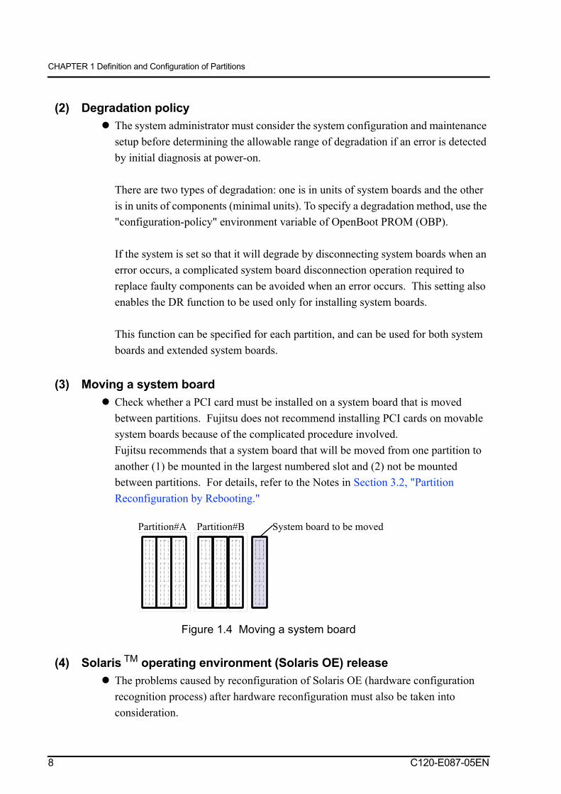
(3) Moving a system boardCheck whether a PCI card must be installed on a system board that is moved between partitions. Fujitsu does not recommend installing PCI cards on movable system boards because of the complicated procedure involved.Fujitsu recommends that a system board that will be moved from one partition to another (1) be mounted in the largest numbered slot and (2) not be mounted between partitions. For details, refer to the Notes in Section 3.2, "Partition Reconfiguration by Rebooting."
Figure 1.4 Moving a system board
(4) Solaris TM operating environment (Solaris OE) releaseThe problems caused by reconfiguration of Solaris OE (hardware configuration recognition process) after hardware reconfiguration must also be taken into consideration.
Partition#A Partition#B System board to be moved
8 C120-E087-05EN

1.4 Key Points When Determining the Partition Configuration
(5) Connection of system volumesUsing a multi-path structure to connect multiple system boards is recommended. If a multi-path structure is not used, access to the system volume becomes impossible if a defective system board degrades the system.If a disk drive installed in the file disk unit (FDU) is used as the system volume, use of dedicated file units for the respective partitions is recommended. However, in a file unit where two or more disk devices are connected by two SCSI buses, a single file unit can be commonly shared by multiple partitions. In this case however, there are limitations on the maintenance of the system boards connected.
(6) Installing the console connection unitsFujitsu recommends using a multi-path structure to connect multiple system boards. The exact system structure recommended depends on whether selection of the dual power feed option is used, and if the redundant system monitoring mechanism is used. If only one console connection unit is used, there are limitations on hot system maintenance of the system boards.
C120-E087-05EN 9

CHAPTER 1 Definition and Configuration of Partitions
1.5 Extended Partitioning (XPAR)
This section describes the extended partitioning (XPAR) that is available on PRIMEPOWER900/1500/2500.
1.5.1 Function overviewWhen XPAR is used on the PRIMEPOWER900/1500/2500, the number of partitions that can be defined for a system board is four times the number that can be defined when PPAR is used.
• PRIMEPOWER2500
When XPAR is used on the PRIMEPOWER2500, a system board with 8 CPUs can be divided into two parts.
When XPAR is used to divide a system board into two parts and both extended system boards (XSBs) are used, at least one PCI/disk box must be connected. (Note)
Note: If the extended partitioning (XPAR) is used, ask the Fujitsu engineer responsible for your equipment.
• PRIMEPOWER900/1500
When XPAR is used on the PRIMEPOWER900/1500, a system board with 8 CPUs into four parts.
When XPAR is used to divide a system board into four parts and the extended system boards (XSBs) on CPUs 4, 5, 6, and 7 are used, a PCI/disk box must be connected. (Note)
Note: If the extended partitioning (XPAR) is used, ask the Fujitsu engineer responsible for your equipment.
The maximum number of partitions to be defined is 15.This extended partitioning function is available for combinations that use a SPARC 64 V processor or later model.
10 C120-E087-05EN

1.5 Extended Partitioning (XPAR)
1.5.2 System board, CPU, and PCI numbersWhen a partition configuration is used for each system board, the system board slot numbers of a processing unit cabinet can be used as system board numbers. Extended partitioning divides resources such as processors, memory, and PCI slots mounted on one system board into extended system boards (XSBs), and specifies each of those XSBs when a partition is defined.
The Table1.1, Table1.2, and Table1.3 show the system board (SB) numbers, CPU numbers, and PCI numbers for PRIMEPOWER900/1500/2500. Two methods are used to indicate system board numbers. In one method, octal numbers (SB#XY or SB#XY-N) that correspond to the mounting slots are used. In the other method, decimal numbers called SB numbers are used.
Table1.1 System board numbers, CPU numbers, and PCI numbers used in PPAR mode and those used in XPAR mode (PRIMEPOWER HPC2500/2500) (1/2)
PSB name SB#00 SB#01 SB#02 SB#03SB No. 0 1 2 3
PPAR CPU 00 02 04 06 08 0A 0C 0E 10 12 14 16 18 1A 1C 1E01 03 05 07 09 0B 0D 0F 11 13 15 17 19 1B 1D 1F
PCI 80 82 84 86 88 8A 8C 8E 90 92 94 96 98 9A 9C 9E81 - 85 87 89 - 8D 8F 91 - 95 97 99 - 9D 9F
XSB name SB#00-1 SB#00-0 SB#01-1 SB#01-0 SB#02-1 SB#02-0 SB#03-1 SB#03-0SB No. 8 0 9 1 10 2 11 3
XPAR CPU 40 42 04 06 48 4A 0C 0E 50 52 14 16 58 5A 1C 1E41 43 05 07 49 4B 0D 0F 51 53 15 17 59 5B 1D 1F
PCI C0 C2 84 86 C8 CA 8C 8E D0 D2 94 96 D8 DA 9C 9EC1 - 85 87 C9 - 8D 8F D1 - 95 97 D9 - 9D 9F
PSB name SB#04 SB#05 SB#06 SB#07SB No. 4 5 6 7
PPAR CPU 20 22 24 26 28 2A 2C 2E 30 32 34 36 38 3A 3C 3E21 23 25 27 29 2B 2D 2F 31 33 35 37 39 3B 3D 3F
PCI A0 A2 A4 A6 A8 AA AC AE B0 B2 B4 B6 B8 BA BC BEA1 - A5 A7 A9 - AD AF B1 - B5 B7 B9 - BD BF
XSB name SB#04-1 SB#04-0 SB#05-1 SB#05-0 SB#06-1 SB#06-0 SB#07-1 SB#07-0SB No. 12 4 13 5 14 6 15 7
XPAR CPU 60 62 24 26 68 6A 2C 2E 70 72 34 36 78 7A 3C 3E61 63 25 27 69 6B 2D 2F 71 73 35 37 79 7B 3D 3F
PCI E0 E2 A4 A6 E8 EA AC AE F0 F2 B4 B6 F8 FA BC BEE1 - A5 A7 E9 - AD AF F1 - B5 B7 F9 - BD BF
C120-E087-05EN 11

CHAPTER 1 Definition and Configuration of Partitions
PSB name SB#10 SB#11 SB#12 SB#13SB No. 8 9 10 11
PPAR CPU 40 42 44 46 48 4A 4C 4E 50 52 54 56 58 5A 5C 5E41 43 45 47 49 4B 4D 4F 51 53 55 57 59 5B 5D 5F
PCI C0 C2 C4 C6 C8 CA CC CE D0 D2 D4 D6 D8 DA DC DEC1 - C5 C7 C9 - CD CF D1 - D5 D7 D9 - DD DF
PSB name SB#14 SB#15 SB#16 SB#17SB No. 12 13 14 15
PPAR CPU 60 62 64 66 68 6A 6C 6E 70 72 74 76 78 7A 7C 7E61 63 65 67 69 6B 6D 6F 71 73 75 77 79 7B 7D 7F
PCI E0 E2 E4 E6 E8 EA EC EE F0 F2 F4 F6 F8 FA FC FEE1 - E5 E7 E9 - ED EF F1 - F5 F7 F9 - FD FF
Table1.2 System board numbers, CPU numbers, and PCI numbers used in PPAR mode and those used in XPAR mode (PRIMEPOWER1500) (1/2)
PSB name SB#00 SB#01SB No. 0 1
PPAR CPU 00 02 04 06 08 0A 0C 0E01 03 05 07 09 0B 0D 0F
PCI 80 82 84 86 88 8A 8C 8E81 - 85 - 89 - 8D -
XSB name SB#00-0 SB#00-1 SB#00-2 SB#00-3 SB#01-0 SB#01-1 SB#01-2 SB#01-3SB No. 0 4 8 12 1 5 9 13
XPAR CPU 00 22 44 66 08 2A 4C 6E01 23 45 67 09 2B 4D 6F
PCI 80 A2 C4 E6 88 AA CC EE81 - C5 - 89 - CD -
Table1.1 System board numbers, CPU numbers, and PCI numbers used in PPAR mode and those used in XPAR mode (PRIMEPOWER HPC2500/2500) (2/2)
12 C120-E087-05EN

1.5 Extended Partitioning (XPAR)
PSB name SB#02 SB#03SB No. 2 3
PPAR CPU 10 12 14 16 18 1A 1C 1E11 13 15 17 19 1B 1D 1F
PCI 90 92 94 96 98 9A 9C 9E91 - 95 - 99 - 9D -
XSB name SB#02-0 SB#02-1 SB#02-2 SB#02-3 SB#03-0 SB#03-1 SB#03-2 SB#03-3SB No. 2 6 10 14 3 7 11 15
XPAR CPU 10 32 54 76 18 3A 5C 7E11 33 55 77 19 3B 5D 7F
PCI 90 B2 D4 F6 98 BA DC FE91 - D5 - 99 - DD -
Table1.3 System board numbers, CPU numbers, and PCI numbers used in PPAR mode and those used in XPAR mode (PRIMEPOWER900)
PSB name SB#00 SB#01SB No. 0 1
PPAR CPU 00 02 04 06 08 0A 0C 0E01 03 05 07 09 0B 0D 0F
PCI 80 82 84 86 88 8A 8C 8E81 - 85 - 89 - 8D -
XSB name SB#00-0 SB#00-1 SB#00-2 SB#00-3 SB#01-0 SB#01-1 SB#01-2 SB#01-3SB No. 0 4 8 12 1 5 9 13
XPAR CPU 00 22 44 66 08 2A 4C 6E01 23 45 67 09 2B 4D 6F
PCI 80 A2 C4 E6 88 AA CC EE81 - C5 - 89 - CD -
Table1.2 System board numbers, CPU numbers, and PCI numbers used in PPAR mode and those used in XPAR mode (PRIMEPOWER1500) (2/2)
C120-E087-05EN 13


CHAPTER 2 Guidelines for Determining Partition Configuration
CHAPTER 2 Guidelines for Determining Partition Configuration
1
This chapter describes the practical points for determining partition configuration.
2.1 Policy on Maintenance of the System Board
This section explains the detailed points used to determine the policy on system board maintenance.
2.1.1 Connecting SMCConnect the respective partitions with SMC across the network using the on-board LAN port on the system board. If this interface is used, the following functions are supported:
Installation of Solaris OE and applications from SMC over the networkUse of the Network Time Protocol (NTP) to synchronize the time of the respective partitions with the time of SMCMaintenance of the file devices that are connected to the respective partitions (machine control software function)Saving the log file in each partition and saving the dump file in SMCNotifying the remote support center of each event detected in the processing unit
SMC provides these functions using SCS. For more information, see the System Console Software User's Guide.
The table below shows the connection interface between a network instance and a processing unit supported by SMC. For more information, see the System Console Software Installation Guide.
C120-E087-05EN 15
CHAPTER 2 Guidelines for Determining Partition Configuration
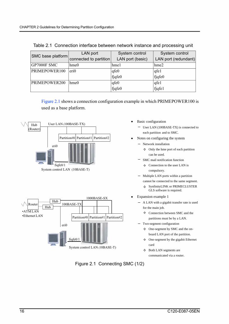
Figure 2.1 shows a connection configuration example in which PRIMEPOWER100 is used as a base platform.
Figure 2.1 Connecting SMC (1/2)
Table 2.1 Connection interface between network instance and processing unit
SMC base platformLAN port
connected to partitionSystem control
LAN port (basic)System control
LAN port (redundant)GP7000F SMC hme0 hme1 hme2PRIMEPOWER100 eri0 qfe0
fjqfe0qfe1fjqfe0
PRIMEPOWER200 hme0 qfe0fjqfe0
qfe1fjqfe1
Partition#0
eri0
System control LAN (10BASE-T)
fiqfe0/1
Partition#1 Partition#2
Hub
(Router)
User LAN (100BASE-TX) Basic configuration
User LAN (100BASE-TX) is connected to
each partition and to SMC.
Notes on configuring the system
Network installation
Only the hme port of each partition
can be used.
SMC mail notification function
Connection to the user LAN is
compulsory.
Multiple LAN ports within a partition
cannot be connected to the same segment.
SynfinityLINK or PRIMECLUSTERGLS software is required.
•ATM LAN
•Ethernet LAN
1000BASE-SX
Partition#0
eri0
System control LAN (10BASE-T)
fiqfe0/1
Partition#1 Partition#2
Hub
HubRouter 100BASE-TX
Expansion example 1
A LAN with a gigabit transfer rate is used
for the main job.
Connection between SMC and the
partitions must be by a LAN.
Two-segment configuration
One-segment by SMC and the on-
board LAN port of the partition.
One-segment by the gigabit Ethernet
card
Both LAN segments are
communicated via a router.
16 C120-E087-05EN

2.1 Policy on Maintenance of the System Board
Figure 2.1 Connecting SMC (2/2)
Port hme0 is normally used as the LAN port for communication with SMC. When other than hme0 is used, the /usr/sbin/FJSVmadm/addevhost command must be used to modify the partition.
To establish communication with the console even though a system board becomes defective or during a hot system swap, the SynfinityLINK or PRIMECLUSTER GLS software must be installed in each partition, and the multiple LAN ports must be connected to the same subnet. If an error is detected, the hubs between SMC and the LAN ports on SMC side can be automatically switched. (Contact Fujitsu's technical staff for support information.) It is also possible to install a spare console to support SMC troubleshooting functions.
2.1.2 Configuration with high availabilityThis section explains a redundant configuration and partition definition.
2.1.2.1 Redundant configurationTo achieve a higher level of availability, the user must implement a redundant configuration for the disk unit, console connection unit (CCU), system control LAN, and power system.
The redundant configuration helps to reduce the effects of a hardware fault. Because it also enables the hot replacement of defective components, the effects of maintenance processing are dramatically reduced.
ATM LAN
Ethernet LAN
1000BASE-SX
Partition#0
eri0
System control LAN
(10BASE-T)
fiqfe0/1
Partition#1 Partition#2
Hub
HubRouter 100BASE-TX
fiqfe2
Expansion example 2
A LAN with a gigabit transfer rate is used
for the main job.
Connection between SMC and the
partitions must be by a LAN.
C120-E087-05EN 17

CHAPTER 2 Guidelines for Determining Partition Configuration
• Redundant configuration for disk unit
Fujitsu recommends that a mirroring mechanism or a disk array unit be used to provide redundancy for the disk unit on which the operating system is installed.
Higher availability can also be obtained by using a redundant configuration for the PCI buses and PCI cards to which the disk units are connected and the system boards (or XSBs) on which PCI cards are mounted.
Note: For disk unit products on which system volumes can be installed, see the related product information.
• Redundant configuration for console path components
The system control LAN and SMC hubs are connected to the serial port of the system board and to the console connection unit for operation from a remote console. This configuration is called a console path.
A redundant configuration of the constituent devices of the console path is recommended to overcome faults in the system board and console connection unit. In the console path, automatic detection of RS-232C cable or serial port fault is supported. Automatic switching of the duplicate configuration is also supported.
Note: Contact Fujitsu's technical staff for support information.
• Redundant configuration for system control mechanism and console connection unit.
If the dual power feed option is used, the system control mechanism and the console connection unit must have a redundant configuration.
At the same time, both of the system control LANs that are installed in each of the two systems must be connected to the console connection unit.
Note1: When two duplicate systems are introduced, a separate power supply must be used for the hubs of the system control LAN of each system and for the console connection unit.
Note2: Consult Fujitsu's technical staff for information about power supply use.
18 C120-E087-05EN

2.1 Policy on Maintenance of the System Board
2.1.2.2 Partition definitionTo use extended partitioning on PRIMEPOWER900/1500/2500, the user must determine partition maintenance policies after consideration of the effects of extending partitioning on the tasks of other partitions.
Even if extended partitioning has been used to divide a system board into extended system boards and to use the extended system boards to configure a partition, replacement must be performed for each system board. There are some cases, however, in which hot replacement of a system board is performed (for example, when each extended system board (XSB) belonging to the same system board is defined on a different partition). In these cases, the user must disconnect each XSB from all of its partitions with the DR function before replacing the system board.
C120-E087-05EN 19

CHAPTER 2 Guidelines for Determining Partition Configuration
2.1.3 Connection of the PCI card to the system boardNote that some I/O devices connected to the system board via the PCI card require that the main power be turned off for hot system maintenance of the system board. See Table 2.2 for a list of PCI cards that require that the main power of the I/O devices be turned off. Typically these PCI card I/O devices include modems or Digital Service Units (DSU). The main power of these devices must be turned off before and during hot system maintenance. If a central modem is used, be careful that turning off the main power of the central modem does not have an adverse effect on other lines.
Note: As of July 2002
Table 2.2 PCI cards that require that the main power of the I/O devices be turned off
PCI card TypePower off of the I/O
device for system board replacement
FDDI X1153A, GP7B8FD2 Not requiredATM X1157A, X1158A, X1159A Not required
GP7B8AT1 Not requiredGigabit Ethernet X1141A, PP028GE1, PW008GE1 Not requiredQuad Fast Ethernet X1034A, PPW008OE1 Not requiredFast Ethernet X1033A Not requiredAP-Net GP7B8AP1, GP7BAP2 Not requiredFibre channel GP7B8FC1, PW008FC2 Not requiredUltra SCSI X6541A (dual Ultra SCSI PCI card) Required
GP7B8SC1, PP028SC1 (Ultra SCSI PCI card of the separated terminating resistor type )
Not required
Line system HIS/P X1155A RequiredSerial X1156A, X2156A RequiredMulti-port communication
GP7B8PC1, GP7B8PC2 Required
ISDN GP7B8PI1 RequiredBasic communication GP7B8BA1 Required
Encryption processor GP7B8CP1 Not required
20 C120-E087-05EN

2.2 Solaris TM OE Release
2.2 Solaris TM OE Release
With Solaris 7 OE or later, the instance numbers of registered devices remain unchanged after reconfiguration. However, in Solaris 2.6 OE, the instance numbers of registered devices may be changed and the operator should be especially careful when adding or removing system boards that mounted in lower numbered slots to the partitions.
2.3 Connection of System Volumes
Fujitsu recommends that the system volume be connected in a redundant configuration (mirroring) as a safeguard against a system failure caused by an error on the disk unit on which the system volume is installed.
2.3.1 PRIMEPOWER800/1000/2000Fujitsu recommends that a system disk be connected to the system board of those forming the partition that is mounted in the lowest numbered slot. This configuration simplifies device selection at installation.
Fujitsu also recommends connecting a mirroring disk unit to the system board mounted in the next lowest numbered slot. When different system boards are used like this, access to the system volume is assured even if a system board becomes faulty or is replaced.
Replacement (maintenance) of the system boards and the file device unit (FDU) must be considered when planning connection of the system volume of PRIMEPOWER800/1000/2000.
Fujitsu recommends that the system volume using the DR function be connected to the system board, which is not to be moved from the partition.
Note 1: For notes on connection and settings, refer to the manuals related to the DR function.
Note 2: Before connecting or disconnecting a SCSI cable from a dual UltraSCSI PCI card, SCSI devices, such as an FDU, must be powered off.
C120-E087-05EN 21

CHAPTER 2 Guidelines for Determining Partition Configuration
The following section explains hot system replacement and the relationship with the PCI SCSI card for each type of connection configuration for the system volume disks.
Available functions depend on the PCI SCSI card. Select the disk connection configuration and PCI card that are suitable for the actual operation.
The connection of the system volume disks is shown in Figure 2.2. The disk connection configuration and selection of the PCI cards must be based on actual operation, because the available functions depend on which PCI SCSI cards are selected. With the dual Ultra SCSI PCI card, the main power of the SCSI device (file device unit) must be turned off before the SCSI cable is connected or disconnected. The term "partition stop state" refers to the state in which the main power of the specified partition has been turned off. The term "partition operating state" refers to the state in which the operating system is running.
• One-to-one connection configuration
If a one-to-one connection configuration is selected, both maintenance by stopping the partition and maintenance by hot system replacement of the system board using the dynamic partition reconfiguration (DR) function can be used.
For actual replacement, either turn off the main power of the system board and the SCSI devices, or if using the Ultra SCSI PCI card with a terminating resistor, disconnect the SCSI cable.
Note1: In the partition stop state, the specified partition is powered off.
Note2: In the partition operating state, the operating system is running.
Figure 2.2 Connection configuration and hot system replacement of a SCSI unit(Relationship with PCI SCSI card: One-to-one connection configuration)
Partition#A
mirroring
Definition of evaluation
Possible
:
:
Possible if effects on other partitions are allowed.
Not possible
:
:
Not possible at present (restricted due to the current maintenance procedure)
GP7B8SCI: Separated terminatingresistor type of Ultra SCSI PCI card
System board replacement (in partitionstop state)
System board replacement (in partitionoperating state)
FDU replacement (in partition stop state) FDU replacement (in parti tion operatingstate)
Disk replacement
X6541A: Dual Ultra SCSI PCI card System board replacement (in partitionstop state)
System board replacement (in partitionoperating state)
FDU replacement (in partition stop state) FDU replacement (in partition operatingstate)
Disk replacement
22 C120-E087-05EN

2.3 Connection of System Volumes
• Two-to-one connection configuration: Connection in which FDU shared
In a two-to-one connection configuration, an Ultra SCSI PCI card with a separate terminating resistor must be selected to perform hot system replacement of the system board.
If the power to a SCSI device, such as the FDU, is disconnected while the dual Ultra SCSI PCI card is being used, the power of both mirrored disk devices is turned off. Under these conditions, hot system replacement of the system board to which the system volume is connected cannot be performed, and maintenance requires stopping of the partition. The same restriction applies to the configuration of tape systems that has multi-paths.
Note1: In the partition stop state, the specified partition is powered off.
Note2: In the partition operating state, the operating system is running.
Figure 2.3 Connection configuration and hot system replacement of SCSI unit(Relationship with PCI SCSI card: Two-to-one connection configuration)
Partition#A
mirroring
Definition of evaluation
Possible
:
:
Possible if effects on other partitions are allowed.
Not possible
:
:
Not possible at present (restricted due to the current maintenance procedure)
X6541A : Dual Ultra SCSI PCI card System board replacement (in partitionstop state)
System board replacement (in partitionoperating state)
FDU replacement (in partition stop state)
FDU replacement (in partition operatingstate)
Disk replacement
GP7B8SCI: Separated terminatingresistor type of Ultra SCSI PCI card
System board replacement (in partitionstop state)
System board replacement (in partitionoperating state)
FDU replacement (in partition stop state)
FDU replacement (in partition operatingstate)
Disk replacement
C120-E087-05EN 23

CHAPTER 2 Guidelines for Determining Partition Configuration
• Two-to-two connection configuration
Hot system replacement of the system board in the two-to-two connection configurations can be enabled if the separated terminating resistor type of Ultra SCSI PCI card is selected.
If a two-to-two connection configuration is selected and the dual Ultra SCSI PCI card is used, hot system replacement of the system board to which the system volume is connected can only be performed by stopping both partitions.
Note1: In the partition stop state, the specified partition is powered off.
Note2: In the partition operating state, the operating system is running.
Figure 2.4 Connection configuration and hot system replacement of SCSI unit(Relationship with PCI SCSI card: Two-to-two connection configuration)
Partition#A
mirroring
Partition#B
Definition of evaluation
Possible
:
:
Possible if effects on other partitions are allowed.
Not possible
:
:
Not possible at present
(restricted due to the current maintenance procedure)
X6541A : Dual Ultra SCSI PCI card
System board replacement (in partitionstop state)
System board replacement (in partitionoperating state)
FDU replacement (in partition stop state)
FDU replacement (in partition operatingstate)
Disk replacement
GP7B8SCI: Separated terminatingresistor type of Ultra SCSI PCI card
System board replacement (in partitionstop state)
System board replacement (in partitionoperating state)
FDU replacement (in partition stop state)
FDU replacement (in partition operatingstate)
Disk replacement
24 C120-E087-05EN

2.4 Connecting the Console Connection Unit (CCU)
2.3.2 PRIMEPOWER900/1500/2500For connection of a PRIMEPOWER900/1500/2500 system volume, Fujitsu recommends that the user uses a built-in disk unit. For PRIMEPOWER2500, the built-in disk unit means a disk unit in a PCI/disk box.
For information about how to use an external SCSI unit (FDU, for example), see Section 2.3.1, "PRIMEPOWER800/1000/2000."
2.3.3 PRIMEPOWER HPC2500For connection of a PRIMEPOWER HPC 2500 system volume, Fujitsu recommends that the user uses a disk bay unit or disk unit in a PCI/disk box.
For information about how to connect a PRIMEPOWER HPC2500 system volume, see Section 2.3.1, "PRIMEPOWER800/1000/2000."
2.4 Connecting the Console Connection Unit (CCU)
SMC is connected via the serial port from the system board and the console connection Unit (CCU) for each partition.
Fujitsu recommends that the console connection unit (CCU) be connected to the serial port of the system board to which the system volume is connected. In the event of a system board failure, or during hot system replacement, use of the RC2000 function (console window display function) requires connection of the two serial ports (redundant configuration). If only one serial port is connected, degradation of the system board connected to the console port or failure of the console connection unit will mean the RC2000 function cannot be used. In these cases, either the console connection unit must be changed to a duplicate configuration or log-on from the network is required. Logging on from the network and operating under root authority, requires prior system definition.
If the CCU is changed to a redundant configuration, the system volume must also be changed to a redundant configuration. In such cases, Fujitsu recommends that the CCU be connected to the system board that is connected to the system volume disk unit.
The hubs between SMC and the LAN ports on SMC side can be automatically switched if an error is detected. (Contact Fujitsu technical staff for the necessary support information.)
C120-E087-05EN 25

CHAPTER 2 Guidelines for Determining Partition Configuration
Figure 2.5 Connections of the console connection unit (CCU)
The connection of the console connection unit (CCU) is explained using as an example that uses a six-port configuration. Note that an 8-port configuration is also provided in addition to the 6-port configuration. Verify the console connection unit supported on each processing unit.
These connections must be specified in the environment variable (tty-conspath, tty-sub-conspath) of OBP (OpenBoot PROM). If they are not yet set, use the serial port of the system board that is mounted in the smallest numbered slot of the system boards (the smallest numbered system board) making up the partition. If no port is set to tty-conspath at the startup of the partition, the port that is set to tty-sub-conspath is automatically switched. If no ports are set to tty-conspath or to tty-sub-conspath at the startup of the partition, the same setting as "not-yet-set" is used. If a multi-path configuration is used and the operating system becomes defective, the drivers perform the switching processing.
For some models, a redundant configuration is defined as the basic configuration. When connection is actually made, verify the configuration.
Console connection unit
Console connection unit
Console connection unit
Console connection unit
Console connection unit
Console connection unit
Console connection unit
Console connection unitConsole connection unit
Redundant configuration
Partition#A Partition#B
Basic configuration
Partition#A Partition#B
Up to 6 (3) partition configuration
Up to 12 (6) partition configuration
Up to 6 partition configuration
Up to 12 partition configurationLog-on from the network is required in the event of a
system board failure or console connection unit
failure if a redundant path is not provided.
The number in parenthesis () indicates the number of
supported partitions if the two console paths are
connected from a single partition.
In the configuration of 12 partitions or more, a total of
6 console connection units are used.
This configuration is required in the dual power-feed
option configuration.
26 C120-E087-05EN

2.4 Connecting the Console Connection Unit (CCU)
When operation is degraded because of a system board fault, a POST (Power On Self Test) diagnostics message may not be displayed regardless of whether tty-conspath is specified.
When tty-conspath or tty-sub-conspath is specified, use a format appropriate for the system board (or extended system board) slot number system. Table 2.3 shows the specifiable parameters.
Note: "None" is the default used to indicate that this property is not specified.
Table 2.3 Parameters specifiable for tty-conspath and tty-sub-conspathPartition Specifiable parameter
System board none, c0s[0-7], c1s[0-7], c2s[0-7], c3s[0-7] Example: c0s2, c1s5
Extended system board (Extended partitioning) none, c0s[0-7]-[0-3] Example: c0s1-0, c0s3-2
C120-E087-05EN 27

CHAPTER 3 How to Change the Partition Configuration
1
This chapter describes how to change the partition configuration using the SCS function.
Note1: Because functions may be added and notes changed or added as a result of SCS function enhancements, be sure to obtain the latest versions of the software and firmware before beginning installation.
Note2: For information about changing the partition configuration using the DR function, refer to the manuals related to DR.
3.1 Reconfiguration Function
This system provides the following two reconfiguration functions:
• Reconfiguration by rebooting
Reconfiguration by rebooting changes the system configuration when the partition power is turned on/off or the partition is rebooted. If the system configuration is changed by this method it means that operations are temporarily stopped from the moment of shutdown to the restarting of applications after rebooting. Because the system is restarted in this method, the configuration can be changed even if the requirements of the dynamic partition reconfiguration (DR) function are not satisfied.
Reconfiguring systems that use SCS versions prior to SCS1.4 requires that the main power of the partition be turned off then on again. In systems using SCS1.4 up to SCS1.5, turning the main power off then on again is required for device disconnection, but installation can be accomplished by rebooting.
For functions provided by each version of SCS, refer to Section 3.2, "Partition Reconfiguration by Rebooting."
• Dynamic partition reconfiguration (DR) function
The DR function adds or deletes system boards that are constituents of the partition without stopping operation of partitions consisting of multiple system boards. The following requirements must be satisfied in order to reconfigure the partition without stopping operations.
C120-E087-05EN 29

CHAPTER 3 How to Change the Partition Configuration
PRIMEPOWER supports the DR function.All the driver programs that control the I/O devices installed on the system board to be added or deleted must support DR.The I/O devices and the network structure must have been defined to allow continuous operation even though partitions are reconfigured.Software that supports the DR function (includes Solaris OE) must be used.
This function also performs hot system maintenance of system boards. Hot replacement of system boards, even in systems that do not dynamically reconfigure partitions while operations are underway, still requires that the above conditions, and those needed for maintenance, be met.
3.2 Partition Reconfiguration by Rebooting
This section outlines of this function and lists the items that must be checked before reconfiguration.
• Overview of partition reconfiguration by rebooting
This function has been expanded by the enhancement of SCS and some of the firmware. The following table lists specific functions.
: Possible × : Not possible ···: No change
Table 3.1 SCS version and partition reconfigurationFunction category
Type of rebooting SCS 1.4 or later SCS 1.5.1 or later
Attachment Rebooting after system failure ··· ···Shutdown (equivalent to init 5) and power-onReset (equivalent to init 6)Forced reset (from operator panel, etc) ··· ···Power-off and -on from SMCForced reset from SMC ··· ···
Disconnection Rebooting after system failure ··· ···Shutdown (equivalent to init 5) and power-on ×
Reset (equivalent to init 6) ×
Forced reset (from operator panel, etc) ··· ···Power-off and -on from SMCForced reset from SMC ··· ···
Setting cancellation function ×
30 C120-E087-05EN

3.2 Partition Reconfiguration by Rebooting
Use of this function makes it possible to quickly reconfigure drivers that do not support DR or PCI cards that do not support hot system replacement. This function also enables operation in which a "configuration-policy" is specified for the board (configuration-policy = board), disconnection of a system board in the event of a failure, and operation in which rebooting is required only for replacement. As a result, the amount of time that the system needs to be stopped for maintenance is reduced.
Note: For systems that cannot be stopped for maintenance, a cluster configuration is the best choice.
• Items to check before reconfiguration
Check the following items before starting reconfiguration:
1 If automatic power control scheduling is used, stop the schedule function before starting reconfiguration.
2 Moving the system board that is connected to the system volume is not recommended.• Using the serial and LAN ports of the system board connected to the system volume
as the CCU connection to SMC is recommended.• The default LAN port connection for SMC is the system board that is mounted in
the smallest numbered slot in the partition. Any interface name can be used as the interface name of this port in the definition file of the system console software.
• When the system volume is moved to the different partition, unless it is reconfigured and mounted, the system volume can not be accessed. This operation is not recommended.
3 There may be cases in which the main power must be turned off in the partition unit before maintenance (replacement) of the system board is started.• Even in systems that support DR, reconfiguration of partitions by rebooting is also
possible. Hot system replacement of the system board is also possible if the required conditions are satisfied.
• Note the following when moving a system board to change a partition configuration:
4 If a SCSI device is commonly shared by the partitions, use the separated terminating resistor version of the Ultra SCSI PCI card.
C120-E087-05EN 31

CHAPTER 3 How to Change the Partition Configuration
5 If reconfiguration is attempted after change in I/O structure, either reboot with reconfigure ("boot -r") or specify reconfigure before shutting down. Note that all device instance numbers are reallocated in Solaris 2.6 OE during reconfiguration.
While the operating system is running, the ok prompt can be displayed by using the forced reset function, and then the operating system can be restarted by executing the boot command. However, if the above operation is executed when partition reconfiguration by rebooting is specified, the partition configuration is changed by the reset at execution of the boot command. To prevent a partition from being reconfigured at an unexpected time, change the configuration of the partition immediately before rebooting. For partition reconfiguration by rebooting, make sure that all of the system boards that are targets of partition reconfiguration are attachable by system console or executing the [drcstat] command before rebooting. Note the following when moving a system board to change a partition configuration:When the physical partitioning (PPAR) that uses system boards as configuration units is used and it is expected that a system board will be moved to the system board pool or another partition, Fujitsu recommends mounting the system board in the highest numbered slot.For example, to move a system board that is mounted between Partition #0 and Partition #1, a diagnostics message (POST) may not be displayed on the console.Also, when the extended partitioning (XPAR) is used and it is expected that the extended system board (XSB) will be pooled or moved, Fujitsu recommends using the XSB with the highest XSB number (XSB No.) in the following table.
(1) PRIMEPOWER900/1500
SB Slot No. 0 1 2 3SB name (SB#XY) 00 01 02 03SB No. 0 1 2 3XSB name (SB#0Y-N) 0-0 0-1 0-2 0-3 1-0 1-1 1-2 1-3 2-0 2-1 2-2 2-3 3-0 3-1 3-2 3-3XSB No. 0 4 8 12 1 5 9 13 2 6 10 14 3 7 11 15
32 C120-E087-05EN

3.2 Partition Reconfiguration by Rebooting
(2) PRIMEPOWER2500• Basic cabinet
• Expansion cabinet (Note)
Note: The extended partition feature (XPAR) cannot be used in an expansion cabinet. For information about conditions for configuring XPAR, refer to the "PRIMEPOWER2500 User's Manual."
SB name Slot No. 0 1 2 3SB name(SB#XY) 00 01 02 03SB No. 0 1 2 3XSB name(SB#XY-N) 00-1 00-0 01-1 01-0 02-1 02-0 03-1 03-0XSB No. (Note) 8 0 9 1 10 2 11 3
SB Slot No. 4 5 6 7SB name(SB#XY) 04 05 06 07SB No. 4 5 6 7XSB name(SB#XY-N) 04-1 04-0 05-1 05-0 06-1 06-0 07-1 07-0XSB No. 12 4 13 5 14 6 15 7
SB Slot No. 0 1 2 3SB name (SB#XY) 10 11 12 13SB No. 8 9 10 11
SB Slot No. 4 5 6 7SB name (SB#XY) 14 15 16 17SB No. 12 13 14 15
C120-E087-05EN 33

CHAPTER 3 How to Change the Partition Configuration
3.3 Operating the Partitions
The followings are four types of partition operations.
Adding a partitionDeleting a partitionDividing a partitionCombining partitions
Figure 3.1 Types of partition operations
Adding a partition
Partition#A Partition#B
New addition
Deleting a partition
Partition#A Partition#B
Deleting a definition
Dividing a partition
Partition#A
Dividing
Partition#A Partition#B
Combining partition
Partition#APartition#A Partition#B
34 C120-E087-05EN

3.3 Operating the Partitions
3.3.1 Adding a partitionA new partition (Partition#B) can be added by the following procedure.
1 Obtain a Host-ID for the partition to be added. For information about obtaining a Host-ID, contact a Fujitsu sales representative.
2 Define Partition#B on the added system board.1 Select System-Specific Administration on the System Console Machine
Administration Menu.2 Select Partition/System Board Administration3 Select System Board Addition to Partition, and define the partition.
3 Install the operating system. When a partition is newly defined (added), initialize the OpenBoot PROM (OBP) environment variable, then install the operating system. (Repeat this procedure for individual setup after set-defaults).
3.3.2 Deleting a partitionPartition#B can be deleted by the following procedure.
1 Select "System-Specific Administration" on the System Console Machine Administration Menu.
2 Select Partition/System Board Administration
3 Select System Board Deletion from Partition, and delete the partition.
C120-E087-05EN 35

CHAPTER 3 How to Change the Partition Configuration
3.3.3 Dividing a partitionDefine a new partition (Partition#B) and assign a system board of an existing partition (Partition#A) by dividing it as follows:
1 Delete the definition of the system board that is to be assigned to Partition#B from SMC.1 Select System-Specific Administration on the System Console Machine
Administration Menu.2 Select Partition/System Board Administration3 Select System Board Deletion from Partition, and delete the partition.
2 Shut down the partition (Partition#A).
3 Define the partition (Partition#B).1 Select System-Specific Administration on the System Console Machine
Administration Menu.2 Select Partition/System Board Administration3 Select System Board Addition to Partition, and register the partition.
4 Start up both partitions.
5 Install the operating system in the newly added Partition#B.
6 Because the number of devices has been reduced in the existing Partition#A, reconfigure the operating system. Either reboot with reconfigure ("boot -r") or specify reconfigure before shutting down.
7 If the system volume was connected to the system board to be deleted, reinstall the operating system in the existing Partition#A.
36 C120-E087-05EN
3.3 Operating the Partitions
3.3.4 Combining partitionsPartition#A and Partition#B can be combined into one partition (Partition#A) by the following procedure:
1 Delete the definition of Partition#B.1 Select System-Specific Administration on the System Console Machine
Administration Menu.2 Select Partition/System Board Administration3 Select System Board Deletion from Partition, and delete the partition.
2 Add the definition of the system board to Partition#A.1 Select System-Specific Administration on the System Console Machine
Administration Menu.2 Select Partition/System Board Administration3 Select System Board Addition to Partition, and register the partition.
After addition of the partition, the operating system must be reconfigured before the devices on the system board can be used.
C120-E087-05EN 37

CHAPTER 3 How to Change the Partition Configuration
3.4 Operating the System Board
The followings are four types of system board operations.
Adding a system boardDeleting a system boardExchanging system boardsMoving a system board
Figure 3.2 Types of system board operations
Adding a system board
New addition
Deleting a system board
Deleting a definition
Exchanging system board
Moving a system board
Partition#A
Partition#A
Partition#A
Partition#A Partition#APartition#B Partition#B
38 C120-E087-05EN

3.4 Operating the System Board
3.4.1 Adding a system boardUse the following procedure to add a system board:
1 Add the system board to the partition that is operating.
After the definition is added, the main power must be turned off or the partition rebooted.
[For SCS versions prior to SCS 1.4]The addition of a definition is only possible while the main power of the corresponding partition is turned off.
[For SCS version SCS 1.4 and later]Setting the partition ID on the system board being added is possible even while the partition is operating. Once set the system board can be installed by rebooting.
2 Because devices such as an on-board LAN port are added, reconfiguration of the operating system is desirable.
Either reboot with reconfigure ("boot -r") or specify reconfiguration before shutting down.
Note1: Note that the device instance numbers can be changed if the system board is added to the smallest numbered slot or if installation of the operating system package is performed in Solaris 2.6 OE.
Note2: In Solaris 7 OE or later, the new device instance number must be reallocated after the operating system is reconfigured.Note that the device instance number that was used before the operating system was reinstalled may not be available, since the device instance number is automatically reallocated when the operating system is reinstalled.
3.4.2 Deleting a system boardUse the following procedure to delete a system board:
1 Delete the system board from the partition definition. Definition is possible while the operating system is operating.
2 After the definition is deleted, the main power of the partition must be turned off and back on again.
3 Because the number of devices is reduced, the partition should be reconfigured. Either reboot with reconfigure ("boot -r") or specify reconfiguration before shutting down.
C120-E087-05EN 39

CHAPTER 3 How to Change the Partition Configuration
3.4.3 Exchanging system boardsUse the following procedure to exchange system boards:
1 Shut down the partition and turn off the main power.
2 While the main power is off, exchange the system boards. Upon completion of the exchange, restart the system.
Note: If the RS-232C and the SCSI interfaces are connected during the exchange, the main power of the connected devices must be turned off. However, if the separated terminating resistor type Ultra SCSI PCI card is used, the SCSI cable can be disconnected without turning off the main power of the SCSI device.
3.4.4 Moving a system boardFirst, turn off the power of the partition from which the system board will be moved off and then on again, then disconnect the system board. Next, either turn on the power of the partition to which the system board will be moved, or reboot it. The system board is added to the target partition.
The procedure for moving a system varies according to whether the version of the SCS used is earlier than SCS1.4. The procedure for each case is provided below.
• For SCS versions prior to SCS 1.4
1 Specify system board detachment while the operating system is running.
2 Turn the main power to the partition off and on again.
3 Turn off the main power to the new location's partition.
4 Add the system board definition to that partition.
5 Turn on the main power to that partition.
• For SCS version 1.4 or later
1 Specify system board detachment while the operating system is running.
2 Turn the main power to the partition off and on again.
40 C120-E087-05EN

3.5 Notes on Changing the Partition Configuration
3 Specify the system board attachment to the new location partition.
4 Reboot that partition or turn its power off and on again.
3.5 Notes on Changing the Partition Configuration
This section provides notes on using SCS to change the partition configuration (for example, removing a system board from a partition or adding a system board to a partition).
On the PRIMEPOWER800/1000/2000 or GP7000F Model 1000/2000, if the partition is powered off and then on again or is rebooted after addition or removal of a system board, the change may not be effective depending on the type of system configuration.
Table 3.2 shows the effectiveness of such changes for each type of system configuration.
Effective: Addition or deletion of the partition is effective.
Not effective: Addition or deletion of the partition is not effective.
Note: In this section, turning the power of a partition off and then on again is explained using as an example a case in which shutdown -i5 is executed on the partition or a system power off instruction and partition stop instruction are executed from SMC.
Table 3.2 Type of system configuration and effectiveness of system board addition and removal
System configurationPower-off
followed by power-on
Reboot
1 One partition (partition ID#0) only Not effective Effective2 One partition (partition ID#0) only:
multiple Host-IDs are registeredNot effective Effective
3 One partition (other than partition ID#0) only: only one Host-ID is registered
Effective Effective
4 One partition (other than partition ID#0) only: multiple Host-IDs are registered
Effective Effective
5 Multiple partitions are configured (Multiple partition IDs are registered)
Effective Effective
C120-E087-05EN 41


Glossary Console Connection Unit (CCU)This device connects SMC with the respective partitions of the main unit. The console functions of the respective partitions are controlled by SMC.
Console windowThis is the console display screen that appears on the SMC window system (CDE) of each partition.
Dual power feed optionThis option enables reception of power from two power sources, and is provided as an option. The option enables continuous system operation even if a single AC input source fails. If the dual power feed option is used for the main unit, Fujitsu recommends connecting uninterruptible power supplies (UPSs) to both of the power sources.
Dynamic Partition Reconfiguration (DR)This function enables the user to change the system configuration without stopping applications. When changing the system configuration, especially when reducing it, certain conditions, such as redundant configuration of the devices and networks being used by the applications, must be satisfied.
Extended system board (XSB)System board is divided into two or four parts for configuration with the extended partition feature (XPAR). XSB is the name of the unit into which the system board is divided.
File Disk Unit (FDU)This unit can be installed in a standard 19-inch rack that can hold multiple disk units.
HmeA type of driver that controls the 10/100MB Ethernet interface. It also controls the 10/100MB Ethernet interface and the LAN card that are installed as standard on the system board.
Instance number of deviceThis is a serial number that is assigned by the operating system to manage devices of a particular type (such as networks and I/O devices).
Multi-path configurationIf multiple access paths are prepared and one is lost or deleted, an alternate access path remains. This is called multi-path configuration. In dynamic partition reconfiguration (DR), where the system board is the unit of addition and deletion, the PCI card on the system board is also added or deleted with the board. Therefore, to allow continued system operation when a system board is removed, the networks and the I/O devices used by the applications use must still be available after the PCI card is deleted. For that purpose, the network and I/O devices that are accessed are configured in a multi-path configuration.
OpenBoot PROM (OBP)This function operates during the power-on and reset of each partition. It recognizes the configuration of processors, memory, and PCI cards and sends the configuration information to the operating system. It also creates and deletes configuration information for the DR function.
C120-E087-05EN 43

Glossary
POSTAn abbreviation of power-on self test. POST is a program module that performs initial settings and diagnosis of a system board and the CPU and memory that are mounted on the system board.
PPARAn abbreviation of physical partitioning. Physical partitioning refers to a partition feature whose configuration unit is the system board.
RC2000This application operates on SMC. The console functions of each partition connected via CCU can be operated as a console window on SMC.
SynfinityLINKThis software supports duplication of the LAN ports and of the network (LAN). The software enables redundant configuration of the LAN without affecting the applications.
Spare consoleThis is the second console and SMC that are installed when configuring SMC in a redundant configuration. It performs functions such as sending notification of system events. Since only one SMC can operate at a time, the command used to switch to the other SMC is available if the first SMC becomes faulty.
System Console Software (SCS)This group of software applications that comprise SMC and implements SMC functions such as setting the functions of the main unit and posting the occurrence of various events. Together with the provision of other main unit functions, an upgraded version includes enhanced SMC functions.
System control LANThis is the LAN that connects SMC with the system monitoring mechanism of the main unit. A local address is assigned to this LAN. Connection with general LAN equipment and with other LANs is prohibited.
System Management Console (SMC)This is a SPARC/Solaris workstation that sets up the main unit and acts as a notification gateway for system events. This device is required in the system because it serves as the maintenance console.
User LANThis type of LAN, generally referred to as the user LAN in this document, is used by the operating systems of the respective partitions. In the main unit, at least one of the LAN ports installed in the system board is considered the default port, and must be connected with SMC using the same subnet. This configuration is required for network installation from SMC.
XPARAn abbreviation of extended partitioning. Extended partitioning refers to a partition feature whose configuration unit is the extended system board (XSB).
44 C120-E087-05EN

Reader’s Comment Form
We would appreciate your comments and suggestions for improving this publication.
Your Comments:
All comments and suggestions become the property of Fujitsu Limited.
Date:_________________________________Your Name:____________________________Company: _____________________________Address: ______________________________City/State/Zip:__________________________Phone/Email address: ____________________
Publication No.:Publication Name:
C120-E087-05ENPartition Operation GuideMay 2003
Page Line Comments
Reply requested: ❏ Yes ❏ No
Good Fair Poor Good Fair Poor Good Fair PoorOrganization:Accuracy:Clarity:Overall rating of this publication:
❏ ❏ ❏❏ ❏ ❏❏ ❏ ❏
❏ ❏ ❏
Use of examples:Index coverage:Cross referencing:
❏ ❏ ❏❏ ❏ ❏
❏ ❏ ❏
Legibility:Binding:Figures and tables:General appearance:
❏ ❏ ❏❏ ❏ ❏❏ ❏ ❏❏ ❏ ❏
Technical level: ❏ Too detailed ❏ Appropriate ❏ Not enough detail
For Users in U.S.A., Canada, and Mexico
Fold and fasten as shown on backNo postage necessary if mailed in U.S.A.
Fujitsu Technology Solutions, Inc.Attention: Solutions Support M/S 2431250 East Arques AvenueP.O. Box 3470Sunnyvale, CA 94088-3470FAX: (408) 746-6813
For Users in Other Countries
Fax this form to the number below or send this form to the address below.
Fujitsu Learning Media LimitedFAX: 81-3-3730-370237-10 Nishi-Kamata 7-chomeOota-KuTokyo 144-0051JAPAN
FUJITSU LIMITED
Please evaluate the overall quality of this manual by checking ( )the appropriate boxes

C120-E087-05EN 46

FOLD AND TAPE
FOLD AND TAPE
BUSINESS REPLY MAILFIRST-CLASS MAIL PERMIT NO 741 SUNNYVALE CA
NO POSTAGE NECESSARY
IF MAILEDIN THE
UNITED STATES
POSTAGE WILL BE PAID BY ADDRESSEE
FUJITSU TECHNOLOGY SOLUTIONS, INC.AT TENTION SOLUTIONS SUPPORT M/S 2431250 EAST ARQUES AVENUEP O BOX 3470SUNNYVALE CA 94088-3470

C120-E087-05EN 48


Back Cover

Information on this document On April 1, 2009, Fujitsu became the sole owner of Fujitsu Siemens Compu-ters. This new subsidiary of Fujitsu has been renamed Fujitsu Technology So-lutions.
This document from the document archive refers to a product version which was released a considerable time ago or which is no longer marketed.
Please note that all company references and copyrights in this document have been legally transferred to Fujitsu Technology Solutions.
Contact and support addresses will now be offered by Fujitsu Technology So-lutions and have the format …@ts.fujitsu.com.
The Internet pages of Fujitsu Technology Solutions are available at http://ts.fujitsu.com/... and the user documentation at http://manuals.ts.fujitsu.com.
Copyright Fujitsu Technology Solutions, 2009
Hinweise zum vorliegenden Dokument Zum 1. April 2009 ist Fujitsu Siemens Computers in den alleinigen Besitz von Fujitsu übergegangen. Diese neue Tochtergesellschaft von Fujitsu trägt seit-dem den Namen Fujitsu Technology Solutions.
Das vorliegende Dokument aus dem Dokumentenarchiv bezieht sich auf eine bereits vor längerer Zeit freigegebene oder nicht mehr im Vertrieb befindliche Produktversion.
Bitte beachten Sie, dass alle Firmenbezüge und Copyrights im vorliegenden Dokument rechtlich auf Fujitsu Technology Solutions übergegangen sind.
Kontakt- und Supportadressen werden nun von Fujitsu Technology Solutions angeboten und haben die Form …@ts.fujitsu.com.
Die Internetseiten von Fujitsu Technology Solutions finden Sie unter http://de.ts.fujitsu.com/..., und unter http://manuals.ts.fujitsu.com finden Sie die Benutzerdokumentation.
Copyright Fujitsu Technology Solutions, 2009